EP3440400B1 - Adaptive led cove lighting system - Google Patents
Adaptive led cove lighting system Download PDFInfo
- Publication number
- EP3440400B1 EP3440400B1 EP17778766.0A EP17778766A EP3440400B1 EP 3440400 B1 EP3440400 B1 EP 3440400B1 EP 17778766 A EP17778766 A EP 17778766A EP 3440400 B1 EP3440400 B1 EP 3440400B1
- Authority
- EP
- European Patent Office
- Prior art keywords
- light
- leds
- cove
- led
- light fixture
- Prior art date
- Legal status (The legal status is an assumption and is not a legal conclusion. Google has not performed a legal analysis and makes no representation as to the accuracy of the status listed.)
- Active
Links
Images







Classifications
-
- F—MECHANICAL ENGINEERING; LIGHTING; HEATING; WEAPONS; BLASTING
- F21—LIGHTING
- F21S—NON-PORTABLE LIGHTING DEVICES; SYSTEMS THEREOF; VEHICLE LIGHTING DEVICES SPECIALLY ADAPTED FOR VEHICLE EXTERIORS
- F21S8/00—Lighting devices intended for fixed installation
- F21S8/03—Lighting devices intended for fixed installation of surface-mounted type
- F21S8/033—Lighting devices intended for fixed installation of surface-mounted type the surface being a wall or like vertical structure, e.g. building facade
-
- F—MECHANICAL ENGINEERING; LIGHTING; HEATING; WEAPONS; BLASTING
- F21—LIGHTING
- F21V—FUNCTIONAL FEATURES OR DETAILS OF LIGHTING DEVICES OR SYSTEMS THEREOF; STRUCTURAL COMBINATIONS OF LIGHTING DEVICES WITH OTHER ARTICLES, NOT OTHERWISE PROVIDED FOR
- F21V21/00—Supporting, suspending, or attaching arrangements for lighting devices; Hand grips
- F21V21/02—Wall, ceiling, or floor bases; Fixing pendants or arms to the bases
- F21V21/025—Elongated bases having a U-shaped cross section
-
- F—MECHANICAL ENGINEERING; LIGHTING; HEATING; WEAPONS; BLASTING
- F21—LIGHTING
- F21V—FUNCTIONAL FEATURES OR DETAILS OF LIGHTING DEVICES OR SYSTEMS THEREOF; STRUCTURAL COMBINATIONS OF LIGHTING DEVICES WITH OTHER ARTICLES, NOT OTHERWISE PROVIDED FOR
- F21V21/00—Supporting, suspending, or attaching arrangements for lighting devices; Hand grips
- F21V21/08—Devices for easy attachment to any desired place, e.g. clip, clamp, magnet
- F21V21/088—Clips; Clamps
-
- F—MECHANICAL ENGINEERING; LIGHTING; HEATING; WEAPONS; BLASTING
- F21—LIGHTING
- F21V—FUNCTIONAL FEATURES OR DETAILS OF LIGHTING DEVICES OR SYSTEMS THEREOF; STRUCTURAL COMBINATIONS OF LIGHTING DEVICES WITH OTHER ARTICLES, NOT OTHERWISE PROVIDED FOR
- F21V23/00—Arrangement of electric circuit elements in or on lighting devices
- F21V23/001—Arrangement of electric circuit elements in or on lighting devices the elements being electrical wires or cables
-
- F—MECHANICAL ENGINEERING; LIGHTING; HEATING; WEAPONS; BLASTING
- F21—LIGHTING
- F21V—FUNCTIONAL FEATURES OR DETAILS OF LIGHTING DEVICES OR SYSTEMS THEREOF; STRUCTURAL COMBINATIONS OF LIGHTING DEVICES WITH OTHER ARTICLES, NOT OTHERWISE PROVIDED FOR
- F21V23/00—Arrangement of electric circuit elements in or on lighting devices
- F21V23/001—Arrangement of electric circuit elements in or on lighting devices the elements being electrical wires or cables
- F21V23/002—Arrangements of cables or conductors inside a lighting device, e.g. means for guiding along parts of the housing or in a pivoting arm
-
- F—MECHANICAL ENGINEERING; LIGHTING; HEATING; WEAPONS; BLASTING
- F21—LIGHTING
- F21V—FUNCTIONAL FEATURES OR DETAILS OF LIGHTING DEVICES OR SYSTEMS THEREOF; STRUCTURAL COMBINATIONS OF LIGHTING DEVICES WITH OTHER ARTICLES, NOT OTHERWISE PROVIDED FOR
- F21V29/00—Protecting lighting devices from thermal damage; Cooling or heating arrangements specially adapted for lighting devices or systems
- F21V29/50—Cooling arrangements
- F21V29/502—Cooling arrangements characterised by the adaptation for cooling of specific components
- F21V29/508—Cooling arrangements characterised by the adaptation for cooling of specific components of electrical circuits
-
- F—MECHANICAL ENGINEERING; LIGHTING; HEATING; WEAPONS; BLASTING
- F21—LIGHTING
- F21V—FUNCTIONAL FEATURES OR DETAILS OF LIGHTING DEVICES OR SYSTEMS THEREOF; STRUCTURAL COMBINATIONS OF LIGHTING DEVICES WITH OTHER ARTICLES, NOT OTHERWISE PROVIDED FOR
- F21V29/00—Protecting lighting devices from thermal damage; Cooling or heating arrangements specially adapted for lighting devices or systems
- F21V29/50—Cooling arrangements
- F21V29/70—Cooling arrangements characterised by passive heat-dissipating elements, e.g. heat-sinks
-
- F—MECHANICAL ENGINEERING; LIGHTING; HEATING; WEAPONS; BLASTING
- F21—LIGHTING
- F21V—FUNCTIONAL FEATURES OR DETAILS OF LIGHTING DEVICES OR SYSTEMS THEREOF; STRUCTURAL COMBINATIONS OF LIGHTING DEVICES WITH OTHER ARTICLES, NOT OTHERWISE PROVIDED FOR
- F21V3/00—Globes; Bowls; Cover glasses
- F21V3/02—Globes; Bowls; Cover glasses characterised by the shape
-
- F—MECHANICAL ENGINEERING; LIGHTING; HEATING; WEAPONS; BLASTING
- F21—LIGHTING
- F21V—FUNCTIONAL FEATURES OR DETAILS OF LIGHTING DEVICES OR SYSTEMS THEREOF; STRUCTURAL COMBINATIONS OF LIGHTING DEVICES WITH OTHER ARTICLES, NOT OTHERWISE PROVIDED FOR
- F21V5/00—Refractors for light sources
- F21V5/04—Refractors for light sources of lens shape
-
- F—MECHANICAL ENGINEERING; LIGHTING; HEATING; WEAPONS; BLASTING
- F21—LIGHTING
- F21S—NON-PORTABLE LIGHTING DEVICES; SYSTEMS THEREOF; VEHICLE LIGHTING DEVICES SPECIALLY ADAPTED FOR VEHICLE EXTERIORS
- F21S2/00—Systems of lighting devices, not provided for in main groups F21S4/00 - F21S10/00 or F21S19/00, e.g. of modular construction
-
- F—MECHANICAL ENGINEERING; LIGHTING; HEATING; WEAPONS; BLASTING
- F21—LIGHTING
- F21Y—INDEXING SCHEME ASSOCIATED WITH SUBCLASSES F21K, F21L, F21S and F21V, RELATING TO THE FORM OR THE KIND OF THE LIGHT SOURCES OR OF THE COLOUR OF THE LIGHT EMITTED
- F21Y2103/00—Elongate light sources, e.g. fluorescent tubes
- F21Y2103/10—Elongate light sources, e.g. fluorescent tubes comprising a linear array of point-like light-generating elements
-
- F—MECHANICAL ENGINEERING; LIGHTING; HEATING; WEAPONS; BLASTING
- F21—LIGHTING
- F21Y—INDEXING SCHEME ASSOCIATED WITH SUBCLASSES F21K, F21L, F21S and F21V, RELATING TO THE FORM OR THE KIND OF THE LIGHT SOURCES OR OF THE COLOUR OF THE LIGHT EMITTED
- F21Y2115/00—Light-generating elements of semiconductor light sources
- F21Y2115/10—Light-emitting diodes [LED]
-
- H—ELECTRICITY
- H02—GENERATION; CONVERSION OR DISTRIBUTION OF ELECTRIC POWER
- H02G—INSTALLATION OF ELECTRIC CABLES OR LINES, OR OF COMBINED OPTICAL AND ELECTRIC CABLES OR LINES
- H02G3/00—Installations of electric cables or lines or protective tubing therefor in or on buildings, equivalent structures or vehicles
- H02G3/02—Details
- H02G3/04—Protective tubing or conduits, e.g. cable ladders or cable troughs
- H02G3/0431—Wall trunking
-
- H—ELECTRICITY
- H02—GENERATION; CONVERSION OR DISTRIBUTION OF ELECTRIC POWER
- H02G—INSTALLATION OF ELECTRIC CABLES OR LINES, OR OF COMBINED OPTICAL AND ELECTRIC CABLES OR LINES
- H02G3/00—Installations of electric cables or lines or protective tubing therefor in or on buildings, equivalent structures or vehicles
- H02G3/36—Installations of cables or lines in walls, floors or ceilings
- H02G3/38—Installations of cables or lines in walls, floors or ceilings the cables or lines being installed in preestablished conduits or ducts
Definitions
- the subject disclosure relates to LED electric lighting fixtures, and more particularly to LED light fixture apparatus configured to project light from a cove or other architectural feature into an adjacent room space.
- LED electric light fixtures have been constructed in the past, for example, such as those disclosed in U.S. Patents 7,726,840 and 8,864,347 , both assigned to Tempo Industries, LLC.
- Other light fixtures specifically designed as cove lights, are known from the United States patent application publications US 2007/0081325 A1 , US 2009/129093 A1 , US 2013/314907 A1 .
- US 2011/0222268 A1 a wall light system including a horizontally extending light shield and using LED's is known.
- the light fixture component and the wall piece are attached together such that one or more LEDs in the light fixture component are positioned at an angle selected to project light from the LEDs on the surface to be illuminated.
- the wall piece is then attached to a wall, and the light fixture component is attached to the wall piece such that each of the one or more LEDs is spaced at a selected distance from the surface to be illuminated.
- Illustrative methods further contemplate attaching the wall piece to a structural surface of predictable integrity so that planned light distributions are not altered during the construction phase of building projects. Overall, an end user is assured a predictable, controlled lighting effect.
- FIG. 1 An illustrative embodiment of an LED cove light system 11 is shown in FIG. 1 .
- FIG. 1 illustrates a cove 13 having a back wall 15, a front wall 19, and a bottom 17, which, in the illustrative embodiment, form a channel 20 of rectangular cross-section.
- the front wall 19, may be, for example, 5.1 - 15.2 cm (2 to 6 inches) high.
- a cove light fixture 21 is attached to the back wall 15.
- the illustrative cove light fixture 21 includes a wall piece or mounting track 22 and an LED fixture component 23, which carries one or more LEDs, LED modules, or LED lighting devices, e.g. 25.
- the top edge 27 of the wall piece 22 lies at the same height as the top edge 29 of the front wall 19 of the cove 13.
- the wall piece 22 may be constructed of thermally conductive plastic or a composite polycarbonate.
- the LED light fixture component 23 is constructed to clip on to the wall piece 22 at a predetermined fixed angle of, for example, 20 degrees to the horizontal, and the one or more LEDs 25 are positioned as high as possible toward the top edges 27, 29.
- adjacent fixture units are shipped clipped together and include a length adjustment feature, which allows the overall length of a number of interconnected units to be adjusted.
- each LED light module 23 directs LED-generated light through a respective lens 28 ( FIG. 3 ).
- lenses 28 may be used to tailor the light output pattern of the LEDs 25 in a desired manner.
- lenses 28 may also protect the LEDs 25 and/or assist in sealing the modules 23, 24.
- the system is configured to optimize the distribution of available light in a pattern 32 such as illustrated in FIG. 2 .
- optics may be used to assist in projecting light from the cove 13 out into the room 31 to contribute to the useable ambient light in the space, to provide a more pleasing effect to the eye, to eliminate the possibility of glare, and to assist in meeting modern energy codes and requirements (e. g. ASHRAE 90.1) requiring a certain power density W/m 2 (W/sq ft) that can be attributed to lighting.
- Optics may be employed, for example, to shift the normal light distribution pattern 30 to a more desirable distribution, e.g. 32.
- the light distribution may varied by changes in the lens 28 or the addition of a reflective surface positioned below the LEDs 25 and attached to the printed circuit board 47.
- the first module 23 includes a base component 40, left and right shield components 43, 53, a module top 45, a printed circuit board (PCB) 47, and a dome lens 28.
- the second module 24 includes a power through base component 50, left and right shields 51, 53, a module top 45, a PCB 47 and a dome lens 28.
- the respective module tops 45 close the respective base components 40, 50 and receive and mount the PCB's 47.
- the respective left and right shields 43, 53 cover holes in the bottom of base component 40 in order to be compliant with U.L. listing requirements for electrical safety since line voltage wires pass through the cavity formed by components 40 and 45 and attach to the input PCBA 73.
- FIG. 3 illustrates one embodiment of such an interconnection assembly, which includes an extension-reduction slide component 63, an extension retaining clip 65, and a wireway cover 67. These components are further illustrated in FIG. 10 .
- Embodiments of an interconnection assembly enabling linear movement of adjacent modules are also taught in U.S. Patent Publication 2014/0307438, published October 16, 2014 .
- A.C. power is introduced into the first module 23 by a male 3-pin connector assembly 55, which plugs into an opening 56 in the base 40.
- A.C power may then exit the second base 50 via a female end cap 3-pin connector 57, which may cooperate with three female receptacles 59.
- Power is supplied to each of two female in-line connector assemblies 72 and from there to respective A.C. power board assemblies 73.
- the power board assemblies 73 supply conditioned A.C. power to the respective PCB's 47 via respective 4-pin by two- row connectors 75.
- Male power pins 79 provide the return from the PCB's 47 to the A.C. wires 71 via the respective connectors 72.
- the A.C. power feed and conditioning circuitry in the illustrative embodiments may be constructed as disclosed in U.S. patent application serial no. 14/941,476, filed November 13, 2015 , and entitled "Compact A.C. Powered LED Light Fixture".
- FIG. 4 illustrates a circuit board 47 and associated components in more detail.
- the LEDs 25 are arranged linearly along an upper edge of the board 47 and space equally apart.
- the LEDs 25 may be Nichia 757 type LEDs, 0.5 Watts. This positioning of the LEDs 25 assists in obtaining various desired light distribution patterns by placing the LEDs 25 near or at the height level of the front cove wall 19 ( FIG. 1 ).
- the LEDs 25 may be positioned 1.3 cm (one half inch) below the top edge 29 of the cove wall 19.
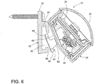
- FIGS. 6-8 show an illustrative embodiment of an interconnection mechanism for joining a wall piece 22 and a light fixture module, e.g. 23.
- the wall piece 22 has a central channel 81 of generally rectangular cross-section having an open entry way 83.
- the bottom surface 85 of the light fixture module 23 is cantilevered to have linear lower and upper segments 87, 89 which meet an obtuse angle "A.”
- a latch member 91 is attached to the upper segment 89 and has a leg 93 and a foot 95.
- the channel 81 runs the entire length of the wall piece 22, and the foot 95 is positioned at two locations on the light fixture module 23. This need not be the case in other embodiments.
- the latch member 91, channel 81 and entry way 83 are so shaped and dimensioned that the upper end 99 of the foot 95 may be inserted into the upper end of the channel 81, which enables the lower end 97 of the foot 95 to swing into the channel 81, as indicated by arrow 101 in FIG. 7 .
- the foot 95 may be dropped down into the interconnected or attached position shown in FIG. 8 .
- the LED 25 is disposed at a selected angle, for example, 20 degrees to the horizontal, as discussed above.
- the cantilevered bottom surface on the light fixture module 23 facilitates this interconnection mechanism. In this manner, a tool-less interconnection and installation of the light fixture module 23 and the wall piece 22 is achieved.
- FIG. 9 illustrates a lighting pattern achievable according to illustrative embodiments in a room with vertical walls 401, 405 lying perpendicular to a ceiling 403.
- the vertical walls 401, 405 meet with the ceiling 403 at respective edges 404, 410.
- the vertical cove back wall 15 lies against the vertical wall 401.
- the Candela curve of maximum intensity 400 forms about a line 402 perpendicular to the surface of the circuit board 47 carrying the LEDs 25; however those skilled in the art will appreciate that this maximum intensity direction can be altered by the use of optics.
- 85% efficacy is the ratio of the "useful" light which illuminates a desired surface (i.e. visible to the observer) to that of the light emitted from the luminaire (some of which is lost in the lens 28).
- the terms low, medium and high candle power are used qualitatively because the brightness on the relevant surface i.e. m-cd (ft.-cd) goes as the inverse of the distance squared.
- m-cd ft.-cd
- the fundamentals of uniform lighting are primarily based on the ratio of intensity in the direction from the source to the task.
- a source that is aimed directly at a task is easily expressed as the Candela (Candlepower) divided by the distance to the task squared, (Cp/D ⁇ 2).
- Candela Chippower
- Cp/D ⁇ 2 the distance to the task squared
- the light toward the farthest area needs to be ten times that of the closest area with the mid-range blending from low to high in order to achieve good uniformity.
- the human eye can notice a lighting ratio of approximately 3:1, therefore, good uniformity with no shadows or hot spots would be considered outstanding.
- a single luminous ceiling plane can be achieved.
- a system which delivers 85% efficacy from the cove can provide the primary light in the space, entirely eliminating the need for downlights, typically provided by downlight "cans," and resulting in tremendous savings in construction costs in various applications.
- Performance may be enhanced further in some embodiments by employing high light reflectance value (LR greater than 70) paint or other finish on a ceiling or other surface.
- An 85% efficacy rating can be contrasted to fluorescent strips where 40% of the light exits the cove and to prior LED linear fixtures where 60% of the light exits the cove.
- the first light fixture wireway module 123 includes a first base component 140, a heat sink 145, a printed circuit board (PCB) 147, and a lens 127.
- the second light fixture wireway module 124 includes a second base component 150 and a lens 127.
- the second light fixture wireway module 124 also includes a heat sink and a PCB, which may be constructed and positioned identically to heat sink 145 and PCB 147, but which are not shown for purposes of clarity of illustration.
- the respective heat sinks, e.g. 145 close the respective first and second wireway module components 140, 150 and receive and mount the PCB's 147.
- the heat sinks comprise generally rectangular trays, which snugly receive the PCB's, e.g. 147.
- the PCB 147 may be attached to the trays, for example, mechanical fasteners 200, 207, or in other embodiments by thermally conductive adhesive tape.
- the base component 140 comprises a power input base and the base component 150 comprises a power output base.
- the PCB 147 may comprise an LED board mounting one or more LEDs. In one embodiment, the PCB 147 may mount twelve LEDs in a row, each of which collectively receive up to 10 watts of power at 120 volts A.C.
- a first captive panel screw 200 inserts through holes 201, 203, and 204, then through a retainer ring 205, which holds screw 200 captive upon removal of the heat sink 145 from the base 140, and finally threads into a hole 206 in a top surface of the first base component 140.
- a second captive panel screw 207 inserts through holes 208, 209, 210, then through a retainer ring 211 and finally threads into a hole 212 in a boss 213 formed on an inner side surface of the first base component 140.
- each lens 127 has a flat portion and an arcuate portion 148 ( FIG. 13 ).
- the arcuate portion 148 has a constant radius so as to avoid sharp edges which would generate non-uniformity in the distributed light, i.e. artifacts or a "prism effect.”
- the arcuate portion 148 has no "optic" effect on the light passing through it, but in other embodiments could provide an optic effect, for example, to generate a primary beam like that shown in FIG. 9 .
- the thickness of the lens 17 is determined by the selected lens material and U.L. requirements.
- the illustrative embodiment of Fig. 11 further includes a reflector component 149, which may be made of, for example, metal or a reflective coated plastic.
- the reflector 149 may have a parabolic contour.
- the reflector component 149 is positioned beneath the LEDs 125 so as to redirect light from the LEDs 125 in an upward direction, thereby assisting in reflecting more useful light out of the fixture 123.
- the left and right light fixture modules 123, 124 are connected together by an interconnection assembly which enable the modules 123, 124 to move linearly towards and away from each other to allow the distance between the modules 123, 124 to be adjusted, while at the same time meeting safety requirements for shielding a line voltage cable 220 as it passes between the respective base components 140, 150.
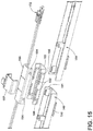
- FIG.15 illustrates one embodiment of such an interconnection assembly, which includes a wire transfer base component 163, a wire transfer cover 165 and a clip-on spacer 167.
- the ridges, e.g. 162, on each outer side of the wire transfer base 163 ride in complementary slots formed on the inner sides of the base components 140, 150, allowing the wire transfer base 163 to slide in and out with respect to the base components 140, 150, to thereby vary the distance between the respective base components 140,150.
- Bosses, e.g. 164, on the outside of the wire transfer cover 165 snap into oppositely disposed holes 166 in the wire transfer base 163.
- the wireway cover 167 snaps into place and holds the base components 140, 150 a fixed distance apart, for example, for shipping purposes.
- the wireway cover 167 may be removed to permit the distance between the base components 140, 150 to be decreased, after which the base components 140, 150 may be screwed or otherwise fastened to an adjacent surface to fix them into place at the selected separation distance.
- illustrative embodiments provide a linear collapsing feature, which can assist in accommodating shorter than expected wall lengths.
- Embodiments of an interconnection assembly enabling linear movement of adjacent modules are also taught in U.S. Patent Publication 2014/0307438, published October 16, 2014 .
- A.C. power is introduced into the first light fixture module 123 by a male 3-pin connector 155.
- the electrical cable 159 which exits the connector 155 is attached by a cable clamp 156 to the power input base 140 and then is clamped by and electrically connected to an electrical connector 172.
- the electrical connectors 172 may be fabricated of first and second halves arranged to pierce the insulation of the electrical cables 159, 161, for example, as illustrated in U.S. Patent 9,458,995 .
- the electrical connectors 172 are connected to A.C. power supply and conditioning circuitry like that illustrated in Figure 1 where power is supplied to each of two female in-line connector assemblies 72 and from there to respective A.C. power board assemblies 73.
- the power board assemblies 73 supply conditioned A.C. power to the respective PCBs 147 via respective 4-pin by two-row connectors 75.
- Male power pins 79 provide the return from the PCB's 147 to the A.C. wires 71 via the respective connectors 72.
- the A.C. power feed and conditioning circuitry may be constructed as disclosed in U.S. Patent Application Serial No. 14/941,476, filed November 13, 2015 , and entitled, "Compact A.C. Powered LED Light Fixture.”
- the LEDs 125 are arranged linearly along an upper edge 148 of the board 147 and spaced equally apart.
- the LEDs 125 may be Nichia 757 type LEDs, 0.5Watts. This positioning of the LEDs 125 assists in obtaining various desired light distribution patterns, for example, by placing the LEDs 125 near or at the height level of a cove wall, such as the cove wall 19 of FIG. 1 .
- the LEDs 125 may be positioned 1.3 cm (one-half inch) below the top edge 29 of the cove wall 19.
- Figure 13 shows an illustrative embodiment of an interconnection mechanism for interconnecting a wall mount hanger or wall piece 122 with a light fixture module, e.g. 123.
- the vertically disposed wall piece 122 has a front surface 183, which forms into a bottom hook portion 185.
- a projection 186 from the side of the wall piece 122 further defines a horizontally running groove 188.
- a bottom surface 184 of the light fixture module 123 is shaped to have linear lower and upper segments 187, 189 which meet an obtuse angle "A1.”
- a lip 191 is formed on the upper segment 189 and fits into the groove 188.
- first and second hooks 193, 195 are formed on the lower segment 187 ( FIG. 12 ) and interlock or engage with the bottom hook 185 of the wall piece 122.
- Various other LED disposition angles A2 for example, such as 10 degrees, may be selected in other embodiments.
- the LEDs 125 are preferably placed as high as possible towards the top edge 152 of the PCB 147.
- the closest the LEDs 125 may be placed to the top edge 152 of the PCB 147 is 0.76 mm (30 thousandths of an inch) due to various design considerations.
- the proper LED angle is automatically achieved upon installation.
- the cooperating parts are so shaped and dimensioned that the upper lip 191 may be inserted into the groove 188, which enables the hook 193 on the light fixture module 123 to snap into or otherwise come into engagement with the bottom hook 185 of the wall piece 122 so as to lock or retain the light fixture module 123 in a pre-determined fixed position with respect to the wall mount hanger 122.
- the LEDs 125 are disposed at the selected angle, for example, 20 degrees to the horizontal, as discussed above. In this manner, a tool-less interconnection and installation of the light fixture module 123 with respect to the wall piece 122 is achieved.
- two principles may be applied: (a) place the LEDs as high as possible in a cove (low loss, optimum light output) and (b) attach the wall piece to a wall or other surface which is a predictable structural surface for fixture mounting purposes.
- a predictable surface is one which an architect or designer can anticipate in advance will not be subject to changes during the construction phase which could disturb the desired lighting effect.
- mounting techniques which propose to mount a cove lighting fixture on the floor or bottom surface of a ceiling cove can be unpredictable because the manner of construction may result in unexpected changes in dimensions or a ceiling cove bottom which is open, exposing studs and gaps between them.
- FIGS. 16-20 illustrate the utility and advantages of illustrative embodiments in various applications.
- a light fixture which employs a lens like that in FIG. 13 is used, as opposed to one with optics that would create a narrower beam such as illustrated in FIG. 9 .
- narrow beam optics could be used in other embodiments.
- FIG. 16 illustrates a tall wall wash embodiment where a light fixture 311 according to illustrative embodiments is mounted in the horizontal bottom 313 of a cove and positioned to throw light on a vertical wall 313.
- the LEDs 317 of the fixture 311 are positioned at a distance "d" from the vertical wall 315. Since this distance "d" can remain the same regardless of the width "w" of the cove bottom 313, reliable pre-positioning of the light fixture 311 without the need for post-installation adjustment is facilitated.
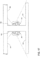
- FIG. 17 illustrates a dual ceiling graze embodiment with respective fixtures 311 disposed on respective side walls 322, 324, above respective horizontal cove walls 321, 323 to illuminate respective ceiling surfaces 325, 327.
- Such an embodiment might be used, for example, down the middle of the ceiling of a room.
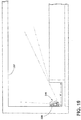
- FIG. 18 show a ceiling graze embodiment where a single fixture 311 is attached to the vertical side wall 329 of a cove above a horizontal bottom cove surface 331 and positioned to illuminate a horizontal ceiling surface 333.
- the distance "w” can be varied, while the distance “d” from the LEDs 317 to the ceiling 333 can be held constant thereby maintaining the desired light distribution, while avoiding post-installation adjustment of the position of the fixture.
- FIG. 19 illustrates a fixture mounted on a vertical sidewall 335 of a cove to provide indirect lighting of a horizontal ceiling 337.
- the width "w" of the cove may vary or the bottom of the cove may be open or irregular, but the desired illumination pattern can still be achieved with the LEDs again spaced a selected fixed distance from the ceiling 337, while avoiding the need for post-installation adjustment.
- FIG. 20 illustrates a wall wash embodiment where a fixture 311 is mounted in a horizontal ceiling 341 adjacent a vertical cove wall 343.
- the distance between the vertical cove wall 343 and the wall 345 being illuminated may vary while the distance "d" between the LEDs and the wall 345 can be maintained the same so as to result in the desired pre-designed illumination pattern.
Landscapes
- Engineering & Computer Science (AREA)
- General Engineering & Computer Science (AREA)
- Architecture (AREA)
- Non-Portable Lighting Devices Or Systems Thereof (AREA)
- Fastening Of Light Sources Or Lamp Holders (AREA)
- Arrangement Of Elements, Cooling, Sealing, Or The Like Of Lighting Devices (AREA)
Description
- The subject disclosure relates to LED electric lighting fixtures, and more particularly to LED light fixture apparatus configured to project light from a cove or other architectural feature into an adjacent room space.
- Various LED electric light fixtures have been constructed in the past, for example, such as those disclosed in
U.S. Patents 7,726,840 and8,864,347 , both assigned to Tempo Industries, LLC. Other light fixtures, specifically designed as cove lights, are known from the United States patent application publicationsUS 2007/0081325 A1 ,US 2009/129093 A1 ,US 2013/314907 A1 . From the United States patent application publicationUS 2011/0222268 A1 , a wall light system including a horizontally extending light shield and using LED's is known. - It is an object of the invention to increase the efficacy of the lighting system by increasing the ratio of the "useful" light which illuminates a desired surface (i.e. visible to the observer). This and other objects are achieved by the subject matter as claimed in the
claim 1. Advantageous further embodiments are claimed in the dependent claims. - For mounting the cove light system, the light fixture component and the wall piece are attached together such that one or more LEDs in the light fixture component are positioned at an angle selected to project light from the LEDs on the surface to be illuminated. The wall piece is then attached to a wall, and the light fixture component is attached to the wall piece such that each of the one or more LEDs is spaced at a selected distance from the surface to be illuminated. Illustrative methods further contemplate attaching the wall piece to a structural surface of predictable integrity so that planned light distributions are not altered during the construction phase of building projects. Overall, an end user is assured a predictable, controlled lighting effect.
-
-
FIG. 1 is a schematic side view of an LED cove light system according to an illustrative embodiment; -
FIG. 2 is a schematic diagram illustrating light distribution patterns according to an illustrative embodiment of the cove light system ofFIG. 1 ; -
FIG. 3 is an exploded perspective view of illustrative light fixture modules for implementing an illustrative system according toFIG. 1 ; -
FIG. 4 is an exploded perspective view illustrating LED placement according to one illustrative embodiment; -
FIG. 5 is a top perspective view of the modules ofFIG. 3 in an assembled state; -
FIG. 6 is a side sectional view illustrating a first step in a procedure for attachment/installation of a light fixture module to a wall piece according to an illustrative embodiment; -
FIG. 7 is a side sectional view illustrating a second step in the procedure ofFIG. 6 ; -
FIG. 8 is a side sectional view illustrating a third step in the procedure ofFIG. 6 ; -
FIG. 9 is a schematic diagram illustrating a light distribution pattern achieved according to illustrative embodiments; -
FIG. 10 is a partial perspective view further illustrating apparatus for interconnecting adjacent light fixture modules according to an illustrative embodiment; -
FIG. 11 is an exploded perspective view of a second illustrative light fixture embodiment; -
FIG. 12 is an enlarged view of a portion of the light fixture embodiment ofFIG.11 ; -
FIG. 13 is a side sectional view of the embodiment ofFIG. 11 in an assembled state; -
FIG. 14 is a side view of the embodiment ofFIG. 11 in an assembled state; -
FIG. 15 is a second enlarged view of a portion of the embodiment ofFIG. 11 . -
FIG. 16 is a schematic diagram illustrating a tall wall wash application of an illustrative embodiment; -
FIG. 17 is a schematic diagram illustrating a dual ceiling graze application of an illustrative embodiment; -
FIG. 18 is a schematic diagram illustrating a single ceiling graze application of an illustrative embodiment; -
FIG. 19 is a schematic diagram illustrating an indirect ceiling cove application of an illustrative embodiment; and -
FIG. 20 is a schematic diagram illustrating a wall wash application of an illustrative embodiment. - An illustrative embodiment of an LED
cove light system 11 is shown inFIG. 1 . In particular,FIG. 1 illustrates acove 13 having aback wall 15, afront wall 19, and abottom 17, which, in the illustrative embodiment, form achannel 20 of rectangular cross-section. In illustrative embodiments thefront wall 19, may be, for example, 5.1 - 15.2 cm (2 to 6 inches) high. - In the illustrative embodiment of
FIG. 1 , acove light fixture 21 is attached to theback wall 15. The illustrativecove light fixture 21 includes a wall piece ormounting track 22 and anLED fixture component 23, which carries one or more LEDs, LED modules, or LED lighting devices, e.g. 25. In an illustrative embodiment, thetop edge 27 of thewall piece 22 lies at the same height as thetop edge 29 of thefront wall 19 of thecove 13. In some embodiments, thewall piece 22 may be constructed of thermally conductive plastic or a composite polycarbonate. - In an illustrative embodiment, the LED
light fixture component 23 is constructed to clip on to thewall piece 22 at a predetermined fixed angle of, for example, 20 degrees to the horizontal, and the one ormore LEDs 25 are positioned as high as possible toward thetop edges - In an illustrative embodiment, each
LED light module 23 directs LED-generated light through a respective lens 28 (FIG. 3 ). As known in the art, in various embodiments,lenses 28 may be used to tailor the light output pattern of theLEDs 25 in a desired manner. In various embodiments,lenses 28 may also protect theLEDs 25 and/or assist in sealing themodules - In illustrative embodiments, the system is configured to optimize the distribution of available light in a
pattern 32 such as illustrated inFIG. 2 . In such systems, optics may be used to assist in projecting light from thecove 13 out into theroom 31 to contribute to the useable ambient light in the space, to provide a more pleasing effect to the eye, to eliminate the possibility of glare, and to assist in meeting modern energy codes and requirements (e. g. ASHRAE 90.1) requiring a certain power density W/m2 (W/sq ft) that can be attributed to lighting. Optics may be employed, for example, to shift the normallight distribution pattern 30 to a more desirable distribution, e.g. 32. In illustrative embodiments, the light distribution may varied by changes in thelens 28 or the addition of a reflective surface positioned below theLEDs 25 and attached to the printedcircuit board 47. - An illustrative embodiment of a pair of adjacent
light fixture modules FIG. 3 . Thefirst module 23 includes abase component 40, left and right shield components 43, 53, amodule top 45, a printed circuit board (PCB) 47, and adome lens 28. Thesecond module 24 includes a power throughbase component 50, left and right shields 51, 53, amodule top 45, aPCB 47 and adome lens 28. Therespective module tops 45 close therespective base components base component 40 in order to be compliant with U.L. listing requirements for electrical safety since line voltage wires pass through the cavity formed bycomponents - The left and right
light fixture modules modules modules FIG. 3 illustrates one embodiment of such an interconnection assembly, which includes an extension-reduction slide component 63, anextension retaining clip 65, and awireway cover 67. These components are further illustrated inFIG. 10 . Embodiments of an interconnection assembly enabling linear movement of adjacent modules are also taught inU.S. Patent Publication 2014/0307438, published October 16, 2014 . - A.C. power is introduced into the
first module 23 by a male 3-pin connector assembly 55, which plugs into an opening 56 in thebase 40. A.C power may then exit thesecond base 50 via a female end cap 3-pin connector 57, which may cooperate with threefemale receptacles 59. Power is supplied to each of two female in-line connector assemblies 72 and from there to respective A.C. power board assemblies 73. The power board assemblies 73 supply conditioned A.C. power to the respective PCB's 47 via respective 4-pin by two-row connectors 75. Male power pins 79 provide the return from the PCB's 47 to theA.C. wires 71 via therespective connectors 72. The A.C. power feed and conditioning circuitry in the illustrative embodiments may be constructed as disclosed in U.S. patent application serial no.14/941,476, filed November 13, 2015 -
FIG. 4 illustrates acircuit board 47 and associated components in more detail. In the illustrative embodiment ofFIG. 4 , theLEDs 25 are arranged linearly along an upper edge of theboard 47 and space equally apart. In one embodiment, theLEDs 25 may be Nichia 757 type LEDs, 0.5 Watts. This positioning of theLEDs 25 assists in obtaining various desired light distribution patterns by placing theLEDs 25 near or at the height level of the front cove wall 19 (FIG. 1 ). In one embodiment, theLEDs 25 may be positioned 1.3 cm (one half inch) below thetop edge 29 of thecove wall 19. -
FIGS. 6-8 show an illustrative embodiment of an interconnection mechanism for joining awall piece 22 and a light fixture module, e.g. 23. As seen inFIG. 6 , thewall piece 22 has acentral channel 81 of generally rectangular cross-section having anopen entry way 83. Thebottom surface 85 of thelight fixture module 23 is cantilevered to have linear lower andupper segments upper segment 89 and has aleg 93 and a foot 95. In one embodiment, thechannel 81 runs the entire length of thewall piece 22, and the foot 95 is positioned at two locations on thelight fixture module 23. This need not be the case in other embodiments. - As illustrated in
FIGS. 6-8 , the latch member 91,channel 81 andentry way 83 are so shaped and dimensioned that the upper end 99 of the foot 95 may be inserted into the upper end of thechannel 81, which enables the lower end 97 of the foot 95 to swing into thechannel 81, as indicated byarrow 101 inFIG. 7 . Once in thechannel 81, the foot 95 may be dropped down into the interconnected or attached position shown inFIG. 8 . In this position, theLED 25 is disposed at a selected angle, for example, 20 degrees to the horizontal, as discussed above. The cantilevered bottom surface on thelight fixture module 23 facilitates this interconnection mechanism. In this manner, a tool-less interconnection and installation of thelight fixture module 23 and thewall piece 22 is achieved. -
FIG. 9 illustrates a lighting pattern achievable according to illustrative embodiments in a room withvertical walls 401, 405 lying perpendicular to aceiling 403. Thevertical walls 401, 405 meet with theceiling 403 atrespective edges 404, 410. The vertical cove backwall 15 lies against thevertical wall 401. - In
Fig. 9 , the Candela curve ofmaximum intensity 400 forms about a line 402 perpendicular to the surface of thecircuit board 47 carrying theLEDs 25; however those skilled in the art will appreciate that this maximum intensity direction can be altered by the use of optics. In connection withFIG. 9 , 85% efficacy is the ratio of the "useful" light which illuminates a desired surface (i.e. visible to the observer) to that of the light emitted from the luminaire (some of which is lost in the lens 28). The terms low, medium and high candle power are used qualitatively because the brightness on the relevant surface i.e. m-cd (ft.-cd) goes as the inverse of the distance squared. Thus, to "throw" light further and achieve the same m-cd (ft.-cd), one needs to start with higher candle power, as would be appreciated by those skilled in the art. - To elaborate, the fundamentals of uniform lighting are primarily based on the ratio of intensity in the direction from the source to the task. A source that is aimed directly at a task is easily expressed as the Candela (Candlepower) divided by the distance to the task squared, (Cp/D^2). When the task is not directly lit from the source, a cosine factor of the angle along with the distance to the task determines the foot-candles and therefore the uniformity (Cp/D^2∗cos). To obtain perfect uniformity, the intensity (Candela) from the source to the outer reaches of the task must be substantially higher than the intensity toward the closest area of the task. Essentially, the light toward the farthest area needs to be ten times that of the closest area with the mid-range blending from low to high in order to achieve good uniformity. The human eye can notice a lighting ratio of approximately 3:1, therefore, good uniformity with no shadows or hot spots would be considered outstanding.

- In embodiments configured, for example, according to
Fig. 9 , a single luminous ceiling plane can be achieved. A system which delivers 85% efficacy from the cove can provide the primary light in the space, entirely eliminating the need for downlights, typically provided by downlight "cans," and resulting in tremendous savings in construction costs in various applications. Performance may be enhanced further in some embodiments by employing high light reflectance value (LR greater than 70) paint or other finish on a ceiling or other surface. An 85% efficacy rating can be contrasted to fluorescent strips where 40% of the light exits the cove and to prior LED linear fixtures where 60% of the light exits the cove. - A second illustrative embodiment of a pair of adjacent light
fixture wireway modules FIG.11 . The first lightfixture wireway module 123 includes afirst base component 140, aheat sink 145, a printed circuit board (PCB) 147, and alens 127. The second lightfixture wireway module 124 includes asecond base component 150 and alens 127. The second lightfixture wireway module 124 also includes a heat sink and a PCB, which may be constructed and positioned identically toheat sink 145 andPCB 147, but which are not shown for purposes of clarity of illustration. The respective heat sinks, e.g. 145, close the respective first and secondwireway module components - In an illustrative embodiment, the heat sinks, e.g. 145, comprise generally rectangular trays, which snugly receive the PCB's, e.g. 147. The
PCB 147 may be attached to the trays, for example,mechanical fasteners base component 140 comprises a power input base and thebase component 150 comprises a power output base. ThePCB 147 may comprise an LED board mounting one or more LEDs. In one embodiment, thePCB 147 may mount twelve LEDs in a row, each of which collectively receive up to 10 watts of power at 120 volts A.C. - Further in
FIG. 11 , a firstcaptive panel screw 200 inserts throughholes retainer ring 205, which holdsscrew 200 captive upon removal of theheat sink 145 from thebase 140, and finally threads into ahole 206 in a top surface of thefirst base component 140. Similarly, a secondcaptive panel screw 207 inserts throughholes retainer ring 211 and finally threads into ahole 212 in aboss 213 formed on an inner side surface of thefirst base component 140. - Further in an illustrative embodiment, each
lens 127 has a flat portion and an arcuate portion 148 (FIG. 13 ). In the illustrative embodiment, thearcuate portion 148 has a constant radius so as to avoid sharp edges which would generate non-uniformity in the distributed light, i.e. artifacts or a "prism effect." In one embodiment, thearcuate portion 148 has no "optic" effect on the light passing through it, but in other embodiments could provide an optic effect, for example, to generate a primary beam like that shown inFIG. 9 . In typical embodiments, the thickness of thelens 17 is determined by the selected lens material and U.L. requirements. - The illustrative embodiment of
Fig. 11 further includes areflector component 149, which may be made of, for example, metal or a reflective coated plastic. In one embodiment, thereflector 149 may have a parabolic contour. As may be appreciated fromFig. 13 , thereflector component 149 is positioned beneath theLEDs 125 so as to redirect light from theLEDs 125 in an upward direction, thereby assisting in reflecting more useful light out of thefixture 123. - In one embodiment, the left and right
light fixture modules modules modules line voltage cable 220 as it passes between therespective base components -
FIG.15 illustrates one embodiment of such an interconnection assembly, which includes a wire transfer base component 163, awire transfer cover 165 and a clip-onspacer 167. In one embodiment, the ridges, e.g. 162, on each outer side of the wire transfer base 163 ride in complementary slots formed on the inner sides of thebase components base components wire transfer cover 165 snap into oppositelydisposed holes 166 in the wire transfer base 163. The wireway cover 167 snaps into place and holds thebase components 140, 150 a fixed distance apart, for example, for shipping purposes. - In various embodiments, the
wireway cover 167 may be removed to permit the distance between thebase components base components U.S. Patent Publication 2014/0307438, published October 16, 2014 . - With reference to
FIG. 11 , A.C. power is introduced into the firstlight fixture module 123 by a male 3-pin connector 155. Theelectrical cable 159 which exits theconnector 155 is attached by a cable clamp 156 to thepower input base 140 and then is clamped by and electrically connected to anelectrical connector 172. - A.C. power exits the
power output base 150 via a female 3-pin connector 157 whosecable 161 electrically interconnects with a secondelectrical connector 172 and is clamped in position by acable clamp 158. In various embodiments, theelectrical connectors 172 may be fabricated of first and second halves arranged to pierce the insulation of theelectrical cables U.S. Patent 9,458,995 - In one illustrative embodiment, the
electrical connectors 172 are connected to A.C. power supply and conditioning circuitry like that illustrated inFigure 1 where power is supplied to each of two female in-line connector assemblies 72 and from there to respective A.C. power board assemblies 73. The power board assemblies 73 supply conditioned A.C. power to therespective PCBs 147 via respective 4-pin by two-row connectors 75. Male power pins 79 provide the return from the PCB's 147 to theA.C. wires 71 via therespective connectors 72. The A.C. power feed and conditioning circuitry may be constructed as disclosed in U.S. Patent Application Serial No.14/941,476, filed November 13, 2015 - In the illustrative embodiment of
FIG. 11 , theLEDs 125 are arranged linearly along anupper edge 148 of theboard 147 and spaced equally apart. In one embodiment, theLEDs 125 may be Nichia 757 type LEDs, 0.5Watts. This positioning of theLEDs 125 assists in obtaining various desired light distribution patterns, for example, by placing theLEDs 125 near or at the height level of a cove wall, such as thecove wall 19 ofFIG. 1 . In one embodiment, theLEDs 125 may be positioned 1.3 cm (one-half inch) below thetop edge 29 of thecove wall 19. -
Figure 13 shows an illustrative embodiment of an interconnection mechanism for interconnecting a wall mount hanger orwall piece 122 with a light fixture module, e.g. 123. As seen inFIG. 13 , the vertically disposedwall piece 122 has afront surface 183, which forms into a bottom hook portion 185. Aprojection 186 from the side of thewall piece 122 further defines a horizontally runninggroove 188. Abottom surface 184 of thelight fixture module 123 is shaped to have linear lower andupper segments lip 191 is formed on theupper segment 189 and fits into thegroove 188. In one embodiment, thegroove 188 runs the entire length of thewall piece 122, and thelip 191 runs the entire length of thelight fixture module 123. In one embodiment, first andsecond hooks FIG. 12 ) and interlock or engage with the bottom hook 185 of thewall piece 122. - In one embodiment, the
LEDs 125 are disposed at an angle A2 of 20 degrees to the horizontal, and the obtuse angle A1 is 180-20 = 160 degrees. Various other LED disposition angles A2, for example, such as 10 degrees, may be selected in other embodiments. In one embodiment, theLEDs 125 are preferably placed as high as possible towards the top edge 152 of thePCB 147. In various embodiments, the closest theLEDs 125 may be placed to the top edge 152 of thePCB 147 is 0.76 mm (30 thousandths of an inch) due to various design considerations. Thus, according to illustrative embodiments, the proper LED angle is automatically achieved upon installation. - In some embodiments, it is also desirable to mount the
LEDs 125 as close as possible to a vertical wall to which thewall piece 122 is attached and as high as possible without exposing theLEDs 125 to view when looking at a vertical wall to which thewall piece 122 is attached along a line of sight which is perpendicular to the vertical wall. In one illustrative embodiment, the dimensions in centimeters (inches) inFIG. 13 may be: d1 = 2.8 (1.11), d2 = 1.3 (0.51), d3 = 1.0 (0.41), d4 = 0.5 (0.20), d5 = 1.1 (0.43), d6 = 4.9 (1.91), and d7 = 0.3 (0.12). These dimensions may of course vary in various applications and embodiments. - In the illustrative embodiment of
FIG. 13 , the cooperating parts are so shaped and dimensioned that theupper lip 191 may be inserted into thegroove 188, which enables thehook 193 on thelight fixture module 123 to snap into or otherwise come into engagement with the bottom hook 185 of thewall piece 122 so as to lock or retain thelight fixture module 123 in a pre-determined fixed position with respect to thewall mount hanger 122. In this position, theLEDs 125 are disposed at the selected angle, for example, 20 degrees to the horizontal, as discussed above. In this manner, a tool-less interconnection and installation of thelight fixture module 123 with respect to thewall piece 122 is achieved. - According to illustrative embodiments, two principles may be applied: (a) place the LEDs as high as possible in a cove (low loss, optimum light output) and (b) attach the wall piece to a wall or other surface which is a predictable structural surface for fixture mounting purposes. A predictable surface is one which an architect or designer can anticipate in advance will not be subject to changes during the construction phase which could disturb the desired lighting effect. For example, mounting techniques which propose to mount a cove lighting fixture on the floor or bottom surface of a ceiling cove can be unpredictable because the manner of construction may result in unexpected changes in dimensions or a ceiling cove bottom which is open, exposing studs and gaps between them.
- The following embodiments shown in
figures 16-18 ,20 are not according to the invention and are present for illustration purposes only.FIGS. 16-20 illustrate the utility and advantages of illustrative embodiments in various applications. In the illustrative examples ofFIGS. 16-20 , a light fixture which employs a lens like that inFIG. 13 is used, as opposed to one with optics that would create a narrower beam such as illustrated inFIG. 9 . Of course narrow beam optics could be used in other embodiments. -
FIG. 16 illustrates a tall wall wash embodiment where alight fixture 311 according to illustrative embodiments is mounted in thehorizontal bottom 313 of a cove and positioned to throw light on avertical wall 313. The LEDs 317 of thefixture 311 are positioned at a distance "d" from the vertical wall 315. Since this distance "d" can remain the same regardless of the width "w" of thecove bottom 313, reliable pre-positioning of thelight fixture 311 without the need for post-installation adjustment is facilitated. -
FIG. 17 illustrates a dual ceiling graze embodiment withrespective fixtures 311 disposed onrespective side walls horizontal cove walls -
FIG. 18 show a ceiling graze embodiment where asingle fixture 311 is attached to the vertical side wall 329 of a cove above a horizontalbottom cove surface 331 and positioned to illuminate ahorizontal ceiling surface 333. Again, the distance "w" can be varied, while the distance "d" from the LEDs 317 to theceiling 333 can be held constant thereby maintaining the desired light distribution, while avoiding post-installation adjustment of the position of the fixture. -
FIG. 19 illustrates a fixture mounted on avertical sidewall 335 of a cove to provide indirect lighting of a horizontal ceiling 337. Again, the width "w" of the cove may vary or the bottom of the cove may be open or irregular, but the desired illumination pattern can still be achieved with the LEDs again spaced a selected fixed distance from the ceiling 337, while avoiding the need for post-installation adjustment. - Finally,
FIG. 20 illustrates a wall wash embodiment where afixture 311 is mounted in ahorizontal ceiling 341 adjacent avertical cove wall 343. Again, the distance between thevertical cove wall 343 and the wall 345 being illuminated may vary while the distance "d" between the LEDs and the wall 345 can be maintained the same so as to result in the desired pre-designed illumination pattern.
Claims (14)
- An LED cove light system (11) mounted to a back surface of a vertical cove wall (15) and including a plurality of light sources; wherein the light sources are one or more LEDs (25, 125, 317) carried by a light fixture component, the light fixture component being removably attachable to a wall piece, the wall piece being attached to said back surface, the LED's being positioned in the light fixture component so as to project light at a selected angle from the cove (13) toward a ceiling (325, 327, 333, 337, 314) of a room when the light fixture component is attached to the wall piece (22, 122);
the wall piece (22, 122) having a top edge (27) which is at the same height as a top surface of a front cove wall (19); and
the one or more LEDs (25, 125, 317) being further positioned so as to not be visible on a line of sight perpendicular to the vertical cove wall (15) from a point looking toward the front cove wall (19) when the light fixture component is attached to the wall piece (22, 122). - The LED cove light system (11) of claim 1 wherein the one or more LEDs (25, 125, 317) comprise a plurality of LEDs (25, 125, 317) mounted in a row adjacent a top edge (27) of a circuit board (47, 147) of said light fixture component (23, 123) but beneath the top surface (29) of the front wall (19) of said cove.
- The LED cove light system (11) of claim 2 wherein the light fixture component (23, 123) and wall piece (22, 122) are configured to enable removable attachment to one another without the use of tools.
- The LED cove light system (11) of claim 1 wherein the wall piece (22, 122) has a horizontal groove (188) formed in a front surface thereof and a hook (185) disposed beneath the horizontal groove (188) and wherein the light fixture component (23, 123) has a lip (191) and a hook (193) located beneath the lip (191), the hook (193) and lip (191) of the light fixture component (23, 123) each being positioned, shaped and dimensioned such that the lip (191) of the light fixture component (23, 123) is insertable into the horizontal groove (188) of the wall piece (22, 122) and the hook (193) of the light fixture component (23, 123) can thereafter come into engagement with the hook (185) of the wall piece (22, 122) to fix the light fixture component (23, 123) in a selected position with respect to the wall piece (22, 122).
- The LED cove light system (11) of claim 4 wherein the light fixture component (23, 123) further comprises a circuit board (47, 147) mounting one or more LEDs (25, 125, 317) and a lens component (28, 127) mounted over the circuit board (47, 147).
- The LED cove light system (11) of claim 5 wherein the lens component (28, 127) comprises a radiused segment located over the one or more LEDs (25, 125, 317).
- The LED cove light system (11) of claim 5 wherein the one or more LEDs (25, 125, 317) comprise a plurality of LEDs (25, 125, 317) mounted in a row adjacent a top edge (27) of the circuit board (47, 147).
- The LED cove light system (11) of claim 7 wherein the row of LEDs (25, 125, 317) is set back from the top edge (27) of the circuit board (47, 147) by a distance in the range of .030 to .060 inches.
- The LED cove light system (11) of claim 5 wherein the LED circuit board (47, 147) comprises a planar LED mounting surface disposed at an angle (A2) of 20 degrees to the horizontal.
- The LED cove light system (11) of claim 1 wherein the selected angle is 20 degrees.
- The LED cove light system (11) of claim 1 wherein said light fixture component (123) further comprises a lens component (127) and a reflector (149) and wherein the lens component (127) is disposed over the plurality of LEDs (125, 317) and has no optic effect on light transmitted through the lens component (127); and wherein the reflector (149) is positioned beneath the plurality of LEDs (125, 317) to redirect light emanating from the plurality of LEDs (125, 317).
- The LED cove light system (11) of claim 11 wherein the plurality of LEDs (125, 317) and the reflector (149) are selected to deliver light to the ceiling (325, 327, 333, 337, 314) sufficient to achieve a single luminous ceiling plane and to provide the primary lighting source to the space beneath the ceiling plane.
- The LED cove light system (11) of claim 12 wherein the plurality of LEDs (125, 317) and the reflector (149) are selected such that the illumination provided to the space is sufficient to illuminate the room without the use of any other lighting fixture or fixtures, including, but not limited to downlight fixtures, including but not limited to downlight cans.
- The LED cove light system of claim 1 wherein the light fixture component (23, 123) further comprises a circuit board (47, 147) mounting a plurality of LEDs (25, 125, 317) in a row; and
wherein the plurality of LEDs (25, 125, 317) are positioned so as to project light out of the cove (13) toward a ceiling (325, 327, 333, 337, 314) of a room with an efficacy of 85% or greater when the wall piece (22, 122) is mounted to the rear vertical wall of the cove (13) and the light fixture component (23, 123) is attached to the wall piece (22, 122); and wherein said light fixture component (123) further comprises a lens component (127) and a reflector (149); and wherein the lens component (127) is disposed over the plurality of LEDs (125, 317) and has no optic effect on light transmitted through the lens component (127); and wherein the reflector (149) is positioned beneath the plurality of LEDs (125, 317) to redirect light emanating from the plurality of LEDs (125, 317) in an upward direction, thereby assisting in reflecting more useful light out of the fixture (23, 123).
Applications Claiming Priority (4)
| Application Number | Priority Date | Filing Date | Title |
|---|---|---|---|
| US201662320517P | 2016-04-09 | 2016-04-09 | |
| US15/335,401 US10151435B2 (en) | 2016-04-09 | 2016-10-26 | Adaptive LED cove lighting system |
| US15/346,650 US9841153B2 (en) | 2016-04-09 | 2016-11-08 | Adaptive LED cove lighting system |
| PCT/IB2017/051941 WO2017175146A1 (en) | 2016-04-09 | 2017-04-05 | Adaptive led cove lighting system |
Publications (3)
| Publication Number | Publication Date |
|---|---|
| EP3440400A1 EP3440400A1 (en) | 2019-02-13 |
| EP3440400A4 EP3440400A4 (en) | 2019-11-20 |
| EP3440400B1 true EP3440400B1 (en) | 2021-05-26 |
Family
ID=60000936
Family Applications (1)
| Application Number | Title | Priority Date | Filing Date |
|---|---|---|---|
| EP17778766.0A Active EP3440400B1 (en) | 2016-04-09 | 2017-04-05 | Adaptive led cove lighting system |
Country Status (3)
| Country | Link |
|---|---|
| US (1) | US9841153B2 (en) |
| EP (1) | EP3440400B1 (en) |
| WO (1) | WO2017175146A1 (en) |
Families Citing this family (15)
| Publication number | Priority date | Publication date | Assignee | Title |
|---|---|---|---|---|
| US10151435B2 (en) * | 2016-04-09 | 2018-12-11 | Tempo Industries, Llc | Adaptive LED cove lighting system |
| US10088122B1 (en) * | 2017-08-04 | 2018-10-02 | Jute Industrial Co., Ltd. | Integrated lamp |
| US10113721B1 (en) * | 2017-11-09 | 2018-10-30 | Ruei-Hsing Lin | LED Lamp |
| CN107816667B (en) * | 2017-11-28 | 2024-04-16 | 赛尔富电子有限公司 | A light distribution system for freezer |
| WO2019233491A1 (en) * | 2018-06-07 | 2019-12-12 | 苏州欧普照明有限公司 | Lamp and lamp assembly |
| WO2020057657A1 (en) * | 2018-09-20 | 2020-03-26 | 欧普照明股份有限公司 | Mounting base for lamp, illuminating assembly, and lamp |
| CN109973850A (en) * | 2019-04-19 | 2019-07-05 | 赛尔富电子有限公司 | A kind of linear light source headlamp |
| US11060711B1 (en) * | 2020-02-21 | 2021-07-13 | Seeless Solutions, Inc. | Lighting cove apparatus and method |
| WO2021231980A1 (en) | 2020-05-15 | 2021-11-18 | Hubbell Incorporated | Light fixture connection system and optic holder |
| US11248779B1 (en) * | 2020-12-24 | 2022-02-15 | Elemental LED, Inc. | LED linear luminaire |
| US11371679B1 (en) | 2020-12-24 | 2022-06-28 | Elemental LED, Inc. | LED linear luminaire |
| CN116783423A (en) * | 2021-01-08 | 2023-09-19 | 昕诺飞控股有限公司 | Lighting fixtures including luminous panels and power rails |
| CN113251387B (en) * | 2021-05-25 | 2022-06-14 | 中建安装集团南京建设有限公司 | High adaptability ceiling lamp suspension bracket |
| US11402083B1 (en) * | 2021-08-18 | 2022-08-02 | Xiamen Pvtech Co., Ltd. | Spliced lamp tube |
| US11306885B1 (en) * | 2021-10-19 | 2022-04-19 | Elemental LED, Inc. | Encapsulated linear lighting with channel |
Family Cites Families (42)
| Publication number | Priority date | Publication date | Assignee | Title |
|---|---|---|---|---|
| US3030670A (en) | 1958-07-15 | 1962-04-24 | Donald W Bigelow | Ceiling construction |
| TW253028B (en) | 1994-03-22 | 1995-08-01 | Daw Technologies Inc | Method and device for improved unidirectional airflow in cleanroom |
| US6351920B1 (en) | 1999-04-22 | 2002-03-05 | Clean Pak International, Inc. | Ceiling module perimeter seal |
| US6592238B2 (en) * | 2001-01-31 | 2003-07-15 | Light Technologies, Inc. | Illumination device for simulation of neon lighting |
| US6805470B1 (en) * | 2003-05-15 | 2004-10-19 | Ardee Lighting/Usa, Inc. | Light fixture including an improved latch mechanism |
| CN101858535A (en) | 2003-07-02 | 2010-10-13 | S·C·约翰松及索恩公司 | Lamps and bulbs for lighting and ambient lighting |
| US7658518B2 (en) | 2005-08-03 | 2010-02-09 | Electrix, Inc. | Cove lighting |
| US20070171631A1 (en) * | 2006-01-25 | 2007-07-26 | Lsi Graphic Solutions Plus | LED cove lighting for exterior fascia |
| US20090129093A1 (en) * | 2007-11-19 | 2009-05-21 | Spi Lighting, Inc. | Shadow-free cove light |
| US20090135597A1 (en) * | 2007-11-27 | 2009-05-28 | Kay Gregory L | Linear lamp |
| US7726840B2 (en) | 2008-03-04 | 2010-06-01 | Tempo Industries, Inc. | Modular LED lighting fixtures |
| US8138690B2 (en) | 2008-04-14 | 2012-03-20 | Digital Lumens Incorporated | LED-based lighting methods, apparatus, and systems employing LED light bars, occupancy sensing, local state machine, and meter circuit |
| US8002426B2 (en) | 2008-10-10 | 2011-08-23 | Tempo Industries, Inc. | Rail light |
| US8361611B2 (en) * | 2009-03-20 | 2013-01-29 | Whiteoptics Llc | Diffusively light reflective paint composition, method for making paint composition, and diffusively light reflective articles |
| EP2233825A1 (en) | 2009-03-25 | 2010-09-29 | Koninklijke Philips Electronics N.V. | Luminaire combining ambient light and task light |
| DE102009016753A1 (en) | 2009-04-07 | 2010-10-14 | Zumtobel Lighting Gmbh | Arrangement for room lighting |
| US8061870B2 (en) | 2009-08-07 | 2011-11-22 | Tempo Industries | Seat light and backlit plaque holder |
| DE102010001777B4 (en) | 2010-02-10 | 2012-08-16 | Insta Elektro Gmbh | lighting device |
| US8398276B2 (en) * | 2010-03-12 | 2013-03-19 | Tempo Industries, Llc | Wall mounted aisle, step and corridor light system |
| AT509646B1 (en) * | 2010-04-09 | 2012-02-15 | Hierzer Andreas | CEILING LIGHT SYSTEM |
| US8616720B2 (en) | 2010-04-27 | 2013-12-31 | Cooper Technologies Company | Linkable linear light emitting diode system |
| US8939634B2 (en) | 2010-06-30 | 2015-01-27 | Abl Ip Holding Llc | Egress lighting for two module luminaires |
| US10883702B2 (en) | 2010-08-31 | 2021-01-05 | Ideal Industries Lighting Llc | Troffer-style fixture |
| CA2830991C (en) | 2011-03-21 | 2020-11-17 | Digital Lumens Incorporated | Methods, apparatus and systems for providing occupancy-based variable lighting |
| US10823347B2 (en) | 2011-07-24 | 2020-11-03 | Ideal Industries Lighting Llc | Modular indirect suspended/ceiling mount fixture |
| US8840278B2 (en) | 2011-09-20 | 2014-09-23 | Cree, Inc. | Specular reflector and LED lamps using same |
| WO2013085874A1 (en) * | 2011-12-05 | 2013-06-13 | Cooledge Lighting Inc. | Control of luminous intensity distribution from an array of point light sources |
| US9488329B2 (en) | 2012-01-06 | 2016-11-08 | Cree, Inc. | Light fixture with textured reflector |
| US8905575B2 (en) | 2012-02-09 | 2014-12-09 | Cree, Inc. | Troffer-style lighting fixture with specular reflector |
| US10378749B2 (en) | 2012-02-10 | 2019-08-13 | Ideal Industries Lighting Llc | Lighting device comprising shield element, and shield element |
| US9494294B2 (en) | 2012-03-23 | 2016-11-15 | Cree, Inc. | Modular indirect troffer |
| US8672508B2 (en) | 2012-04-17 | 2014-03-18 | Tempo Industries, Llc | Scalable LED sconce light |
| US8864347B2 (en) | 2012-04-17 | 2014-10-21 | Tempo Industries, Llc | Concatenatable linear LED lighting fixtures |
| US9261263B2 (en) | 2012-04-23 | 2016-02-16 | Tempo Industries, Llc | Commercial lighting integrated platform |
| US8801237B2 (en) | 2012-04-23 | 2014-08-12 | Tempo Industries, Llc | Modular LED lighting apparatus |
| US8794817B2 (en) | 2012-04-23 | 2014-08-05 | Tempo Industries, Llc | Stringed LED capsule lighting apparatus |
| US9062840B2 (en) | 2012-05-24 | 2015-06-23 | Electrix, Llc | Cove lighting |
| US9989206B2 (en) * | 2013-03-11 | 2018-06-05 | Inception Innovations, Llc | Architectural lighting methods and apparatus |
| US9429283B2 (en) | 2013-04-15 | 2016-08-30 | Tempo Industries, Llc | Adjustable length articulated LED light fixtures |
| US9217247B2 (en) | 2014-02-07 | 2015-12-22 | Apple Inc. | Ceiling system |
| EP2927563A1 (en) * | 2014-04-04 | 2015-10-07 | Emilio Boscagin | A system for supporting led lighting |
| US9458995B1 (en) | 2015-04-10 | 2016-10-04 | Tempo Industries, Llc | Wiring rail platform based LED light fixtures |
-
2016
- 2016-11-08 US US15/346,650 patent/US9841153B2/en not_active Expired - Fee Related
-
2017
- 2017-04-05 EP EP17778766.0A patent/EP3440400B1/en active Active
- 2017-04-05 WO PCT/IB2017/051941 patent/WO2017175146A1/en not_active Ceased
Non-Patent Citations (1)
| Title |
|---|
| None * |
Also Published As
| Publication number | Publication date |
|---|---|
| WO2017175146A1 (en) | 2017-10-12 |
| EP3440400A4 (en) | 2019-11-20 |
| EP3440400A1 (en) | 2019-02-13 |
| US20170292664A1 (en) | 2017-10-12 |
| US9841153B2 (en) | 2017-12-12 |
| WO2017175146A8 (en) | 2018-01-25 |
Similar Documents
| Publication | Publication Date | Title |
|---|---|---|
| US11060676B2 (en) | Adaptive LED cove lighting system | |
| US9841153B2 (en) | Adaptive LED cove lighting system | |
| US10352509B2 (en) | Adaptive LED cove lighting system with micro baffle | |
| US11617254B2 (en) | Solid state lighting fixtures | |
| US10465864B2 (en) | Linear LED light housing | |
| US7771085B2 (en) | Circular LED panel light | |
| CN102947644B (en) | Wall mounted aisle, step and corridor light system | |
| US11408569B2 (en) | Mounting system for retrofit light installation into existing light fixtures | |
| US10539737B2 (en) | Lighting fixture with end plate slots and elongated heat sinks for retaining an edge-lit optical device | |
| US10274171B2 (en) | Adjustable LED light fixture for use in a troffer | |
| US20130308303A1 (en) | Lighting System for an Architectural Ceiling Structure | |
| US20100290229A1 (en) | Field adjustable lighting fixture | |
| CN103534527A (en) | Flat panel lighting device and retrofit kit | |
| US10969535B2 (en) | Waveguide luminaire with side glare shield | |
| US20070258233A1 (en) | Single piece dual coating reflector recessed wall wash luminaire | |
| JP5732613B2 (en) | lighting equipment | |
| EP3467372B1 (en) | Adaptive led cove lighting system with micro baffle | |
| JP2018101479A (en) | Lighting device and heat dissipation member | |
| US20230133237A1 (en) | Suspended luminaire with curved sound dampening panels | |
| GB2574138A (en) | High bay Luminaire | |
| EP4367435B1 (en) | Power track | |
| US11906154B2 (en) | Luminaire with lens having a holographic three-dimensional patterned layer | |
| US20260110424A1 (en) | Lighting device and system for emitting ambient light and direct light | |
| US20260110421A1 (en) | Ambient light emitting light device | |
| EP2993386A1 (en) | Auditorium LED light system |
Legal Events
| Date | Code | Title | Description |
|---|---|---|---|
| STAA | Information on the status of an ep patent application or granted ep patent |
Free format text: STATUS: THE INTERNATIONAL PUBLICATION HAS BEEN MADE |
|
| PUAI | Public reference made under article 153(3) epc to a published international application that has entered the european phase |
Free format text: ORIGINAL CODE: 0009012 |
|
| STAA | Information on the status of an ep patent application or granted ep patent |
Free format text: STATUS: REQUEST FOR EXAMINATION WAS MADE |
|
| 17P | Request for examination filed |
Effective date: 20180928 |
|
| AK | Designated contracting states |
Kind code of ref document: A1 Designated state(s): AL AT BE BG CH CY CZ DE DK EE ES FI FR GB GR HR HU IE IS IT LI LT LU LV MC MK MT NL NO PL PT RO RS SE SI SK SM TR |
|
| AX | Request for extension of the european patent |
Extension state: BA ME |
|
| RIN1 | Information on inventor provided before grant (corrected) |
Inventor name: TOMS, SHAUN Inventor name: LUEKEN, THOMAS Inventor name: BREMSER, MICHAEL D. Inventor name: JOHNSON, JAMES Inventor name: PEARSON, DENNIS |
|
| DAV | Request for validation of the european patent (deleted) | ||
| DAX | Request for extension of the european patent (deleted) | ||
| A4 | Supplementary search report drawn up and despatched |
Effective date: 20191017 |
|
| RIC1 | Information provided on ipc code assigned before grant |
Ipc: F21V 29/508 20150101ALI20191011BHEP Ipc: F21V 23/00 20150101ALI20191011BHEP Ipc: F21S 8/00 20060101AFI20191011BHEP Ipc: F21V 29/70 20150101ALI20191011BHEP Ipc: F21V 5/04 20060101ALI20191011BHEP Ipc: F21V 21/088 20060101ALI20191011BHEP Ipc: F21V 21/02 20060101ALI20191011BHEP |
|
| GRAP | Despatch of communication of intention to grant a patent |
Free format text: ORIGINAL CODE: EPIDOSNIGR1 |
|
| STAA | Information on the status of an ep patent application or granted ep patent |
Free format text: STATUS: GRANT OF PATENT IS INTENDED |
|
| INTG | Intention to grant announced |
Effective date: 20210113 |
|
| GRAS | Grant fee paid |
Free format text: ORIGINAL CODE: EPIDOSNIGR3 |
|
| GRAA | (expected) grant |
Free format text: ORIGINAL CODE: 0009210 |
|
| STAA | Information on the status of an ep patent application or granted ep patent |
Free format text: STATUS: THE PATENT HAS BEEN GRANTED |
|
| AK | Designated contracting states |
Kind code of ref document: B1 Designated state(s): AL AT BE BG CH CY CZ DE DK EE ES FI FR GB GR HR HU IE IS IT LI LT LU LV MC MK MT NL NO PL PT RO RS SE SI SK SM TR |
|
| REG | Reference to a national code |
Ref country code: GB Ref legal event code: FG4D |
|
| REG | Reference to a national code |
Ref country code: CH Ref legal event code: EP |
|
| REG | Reference to a national code |
Ref country code: AT Ref legal event code: REF Ref document number: 1396581 Country of ref document: AT Kind code of ref document: T Effective date: 20210615 |
|
| REG | Reference to a national code |
Ref country code: DE Ref legal event code: R096 Ref document number: 602017039322 Country of ref document: DE |
|
| REG | Reference to a national code |
Ref country code: IE Ref legal event code: FG4D |
|
| REG | Reference to a national code |
Ref country code: LT Ref legal event code: MG9D |
|
| REG | Reference to a national code |
Ref country code: AT Ref legal event code: MK05 Ref document number: 1396581 Country of ref document: AT Kind code of ref document: T Effective date: 20210526 |
|
| PG25 | Lapsed in a contracting state [announced via postgrant information from national office to epo] |
Ref country code: FI Free format text: LAPSE BECAUSE OF FAILURE TO SUBMIT A TRANSLATION OF THE DESCRIPTION OR TO PAY THE FEE WITHIN THE PRESCRIBED TIME-LIMIT Effective date: 20210526 Ref country code: LT Free format text: LAPSE BECAUSE OF FAILURE TO SUBMIT A TRANSLATION OF THE DESCRIPTION OR TO PAY THE FEE WITHIN THE PRESCRIBED TIME-LIMIT Effective date: 20210526 Ref country code: AT Free format text: LAPSE BECAUSE OF FAILURE TO SUBMIT A TRANSLATION OF THE DESCRIPTION OR TO PAY THE FEE WITHIN THE PRESCRIBED TIME-LIMIT Effective date: 20210526 Ref country code: BG Free format text: LAPSE BECAUSE OF FAILURE TO SUBMIT A TRANSLATION OF THE DESCRIPTION OR TO PAY THE FEE WITHIN THE PRESCRIBED TIME-LIMIT Effective date: 20210826 Ref country code: HR Free format text: LAPSE BECAUSE OF FAILURE TO SUBMIT A TRANSLATION OF THE DESCRIPTION OR TO PAY THE FEE WITHIN THE PRESCRIBED TIME-LIMIT Effective date: 20210526 |
|
| REG | Reference to a national code |
Ref country code: NL Ref legal event code: MP Effective date: 20210526 |
|
| PG25 | Lapsed in a contracting state [announced via postgrant information from national office to epo] |
Ref country code: IS Free format text: LAPSE BECAUSE OF FAILURE TO SUBMIT A TRANSLATION OF THE DESCRIPTION OR TO PAY THE FEE WITHIN THE PRESCRIBED TIME-LIMIT Effective date: 20210926 Ref country code: GR Free format text: LAPSE BECAUSE OF FAILURE TO SUBMIT A TRANSLATION OF THE DESCRIPTION OR TO PAY THE FEE WITHIN THE PRESCRIBED TIME-LIMIT Effective date: 20210827 Ref country code: SE Free format text: LAPSE BECAUSE OF FAILURE TO SUBMIT A TRANSLATION OF THE DESCRIPTION OR TO PAY THE FEE WITHIN THE PRESCRIBED TIME-LIMIT Effective date: 20210526 Ref country code: RS Free format text: LAPSE BECAUSE OF FAILURE TO SUBMIT A TRANSLATION OF THE DESCRIPTION OR TO PAY THE FEE WITHIN THE PRESCRIBED TIME-LIMIT Effective date: 20210526 Ref country code: NO Free format text: LAPSE BECAUSE OF FAILURE TO SUBMIT A TRANSLATION OF THE DESCRIPTION OR TO PAY THE FEE WITHIN THE PRESCRIBED TIME-LIMIT Effective date: 20210826 Ref country code: LV Free format text: LAPSE BECAUSE OF FAILURE TO SUBMIT A TRANSLATION OF THE DESCRIPTION OR TO PAY THE FEE WITHIN THE PRESCRIBED TIME-LIMIT Effective date: 20210526 Ref country code: PT Free format text: LAPSE BECAUSE OF FAILURE TO SUBMIT A TRANSLATION OF THE DESCRIPTION OR TO PAY THE FEE WITHIN THE PRESCRIBED TIME-LIMIT Effective date: 20210927 Ref country code: PL Free format text: LAPSE BECAUSE OF FAILURE TO SUBMIT A TRANSLATION OF THE DESCRIPTION OR TO PAY THE FEE WITHIN THE PRESCRIBED TIME-LIMIT Effective date: 20210526 |
|
| PG25 | Lapsed in a contracting state [announced via postgrant information from national office to epo] |
Ref country code: NL Free format text: LAPSE BECAUSE OF FAILURE TO SUBMIT A TRANSLATION OF THE DESCRIPTION OR TO PAY THE FEE WITHIN THE PRESCRIBED TIME-LIMIT Effective date: 20210526 |
|
| PG25 | Lapsed in a contracting state [announced via postgrant information from national office to epo] |
Ref country code: SM Free format text: LAPSE BECAUSE OF FAILURE TO SUBMIT A TRANSLATION OF THE DESCRIPTION OR TO PAY THE FEE WITHIN THE PRESCRIBED TIME-LIMIT Effective date: 20210526 Ref country code: SK Free format text: LAPSE BECAUSE OF FAILURE TO SUBMIT A TRANSLATION OF THE DESCRIPTION OR TO PAY THE FEE WITHIN THE PRESCRIBED TIME-LIMIT Effective date: 20210526 Ref country code: RO Free format text: LAPSE BECAUSE OF FAILURE TO SUBMIT A TRANSLATION OF THE DESCRIPTION OR TO PAY THE FEE WITHIN THE PRESCRIBED TIME-LIMIT Effective date: 20210526 Ref country code: ES Free format text: LAPSE BECAUSE OF FAILURE TO SUBMIT A TRANSLATION OF THE DESCRIPTION OR TO PAY THE FEE WITHIN THE PRESCRIBED TIME-LIMIT Effective date: 20210526 Ref country code: DK Free format text: LAPSE BECAUSE OF FAILURE TO SUBMIT A TRANSLATION OF THE DESCRIPTION OR TO PAY THE FEE WITHIN THE PRESCRIBED TIME-LIMIT Effective date: 20210526 Ref country code: CZ Free format text: LAPSE BECAUSE OF FAILURE TO SUBMIT A TRANSLATION OF THE DESCRIPTION OR TO PAY THE FEE WITHIN THE PRESCRIBED TIME-LIMIT Effective date: 20210526 Ref country code: EE Free format text: LAPSE BECAUSE OF FAILURE TO SUBMIT A TRANSLATION OF THE DESCRIPTION OR TO PAY THE FEE WITHIN THE PRESCRIBED TIME-LIMIT Effective date: 20210526 |
|
| REG | Reference to a national code |
Ref country code: DE Ref legal event code: R097 Ref document number: 602017039322 Country of ref document: DE |
|
| PLBE | No opposition filed within time limit |
Free format text: ORIGINAL CODE: 0009261 |
|
| STAA | Information on the status of an ep patent application or granted ep patent |
Free format text: STATUS: NO OPPOSITION FILED WITHIN TIME LIMIT |
|
| PGFP | Annual fee paid to national office [announced via postgrant information from national office to epo] |
Ref country code: GB Payment date: 20220303 Year of fee payment: 6 |
|
| 26N | No opposition filed |
Effective date: 20220301 |
|
| PG25 | Lapsed in a contracting state [announced via postgrant information from national office to epo] |
Ref country code: IS Free format text: LAPSE BECAUSE OF FAILURE TO SUBMIT A TRANSLATION OF THE DESCRIPTION OR TO PAY THE FEE WITHIN THE PRESCRIBED TIME-LIMIT Effective date: 20210926 Ref country code: AL Free format text: LAPSE BECAUSE OF FAILURE TO SUBMIT A TRANSLATION OF THE DESCRIPTION OR TO PAY THE FEE WITHIN THE PRESCRIBED TIME-LIMIT Effective date: 20210526 |
|
| PGFP | Annual fee paid to national office [announced via postgrant information from national office to epo] |
Ref country code: FR Payment date: 20220308 Year of fee payment: 6 |
|
| PG25 | Lapsed in a contracting state [announced via postgrant information from national office to epo] |
Ref country code: IT Free format text: LAPSE BECAUSE OF FAILURE TO SUBMIT A TRANSLATION OF THE DESCRIPTION OR TO PAY THE FEE WITHIN THE PRESCRIBED TIME-LIMIT Effective date: 20210526 |
|
| PGFP | Annual fee paid to national office [announced via postgrant information from national office to epo] |
Ref country code: DE Payment date: 20220302 Year of fee payment: 6 |
|
| REG | Reference to a national code |
Ref country code: CH Ref legal event code: PL |
|
| PG25 | Lapsed in a contracting state [announced via postgrant information from national office to epo] |
Ref country code: MC Free format text: LAPSE BECAUSE OF FAILURE TO SUBMIT A TRANSLATION OF THE DESCRIPTION OR TO PAY THE FEE WITHIN THE PRESCRIBED TIME-LIMIT Effective date: 20210526 Ref country code: LU Free format text: LAPSE BECAUSE OF NON-PAYMENT OF DUE FEES Effective date: 20220405 Ref country code: LI Free format text: LAPSE BECAUSE OF NON-PAYMENT OF DUE FEES Effective date: 20220430 Ref country code: CH Free format text: LAPSE BECAUSE OF NON-PAYMENT OF DUE FEES Effective date: 20220430 |
|
| PGFP | Annual fee paid to national office [announced via postgrant information from national office to epo] |
Ref country code: BE Payment date: 20221004 Year of fee payment: 6 |
|
| PG25 | Lapsed in a contracting state [announced via postgrant information from national office to epo] |
Ref country code: IE Free format text: LAPSE BECAUSE OF NON-PAYMENT OF DUE FEES Effective date: 20220405 |
|
| REG | Reference to a national code |
Ref country code: DE Ref legal event code: R119 Ref document number: 602017039322 Country of ref document: DE |
|
| GBPC | Gb: european patent ceased through non-payment of renewal fee |
Effective date: 20230405 |
|
| REG | Reference to a national code |
Ref country code: BE Ref legal event code: MM Effective date: 20230430 |
|
| PG25 | Lapsed in a contracting state [announced via postgrant information from national office to epo] |
Ref country code: GB Free format text: LAPSE BECAUSE OF NON-PAYMENT OF DUE FEES Effective date: 20230405 |
|
| PG25 | Lapsed in a contracting state [announced via postgrant information from national office to epo] |
Ref country code: GB Free format text: LAPSE BECAUSE OF NON-PAYMENT OF DUE FEES Effective date: 20230405 Ref country code: FR Free format text: LAPSE BECAUSE OF NON-PAYMENT OF DUE FEES Effective date: 20230430 Ref country code: DE Free format text: LAPSE BECAUSE OF NON-PAYMENT OF DUE FEES Effective date: 20231103 |
|
| PG25 | Lapsed in a contracting state [announced via postgrant information from national office to epo] |
Ref country code: BE Free format text: LAPSE BECAUSE OF NON-PAYMENT OF DUE FEES Effective date: 20230430 |
|
| PG25 | Lapsed in a contracting state [announced via postgrant information from national office to epo] |
Ref country code: HU Free format text: LAPSE BECAUSE OF FAILURE TO SUBMIT A TRANSLATION OF THE DESCRIPTION OR TO PAY THE FEE WITHIN THE PRESCRIBED TIME-LIMIT; INVALID AB INITIO Effective date: 20170405 |
|
| PG25 | Lapsed in a contracting state [announced via postgrant information from national office to epo] |
Ref country code: MK Free format text: LAPSE BECAUSE OF FAILURE TO SUBMIT A TRANSLATION OF THE DESCRIPTION OR TO PAY THE FEE WITHIN THE PRESCRIBED TIME-LIMIT Effective date: 20210526 Ref country code: CY Free format text: LAPSE BECAUSE OF FAILURE TO SUBMIT A TRANSLATION OF THE DESCRIPTION OR TO PAY THE FEE WITHIN THE PRESCRIBED TIME-LIMIT Effective date: 20210526 |
|
| PG25 | Lapsed in a contracting state [announced via postgrant information from national office to epo] |
Ref country code: MT Free format text: LAPSE BECAUSE OF FAILURE TO SUBMIT A TRANSLATION OF THE DESCRIPTION OR TO PAY THE FEE WITHIN THE PRESCRIBED TIME-LIMIT Effective date: 20210526 |
|
| PG25 | Lapsed in a contracting state [announced via postgrant information from national office to epo] |
Ref country code: TR Free format text: LAPSE BECAUSE OF FAILURE TO SUBMIT A TRANSLATION OF THE DESCRIPTION OR TO PAY THE FEE WITHIN THE PRESCRIBED TIME-LIMIT Effective date: 20210526 |