EP3440263B1 - Assembly of track-setting devices and tracked vehicle - Google Patents
Assembly of track-setting devices and tracked vehicle Download PDFInfo
- Publication number
- EP3440263B1 EP3440263B1 EP17724901.8A EP17724901A EP3440263B1 EP 3440263 B1 EP3440263 B1 EP 3440263B1 EP 17724901 A EP17724901 A EP 17724901A EP 3440263 B1 EP3440263 B1 EP 3440263B1
- Authority
- EP
- European Patent Office
- Prior art keywords
- outlet
- hydraulic
- inlet
- track
- tiller
- Prior art date
- Legal status (The legal status is an assumption and is not a legal conclusion. Google has not performed a legal analysis and makes no representation as to the accuracy of the status listed.)
- Active
Links
Images

Classifications
-
- E—FIXED CONSTRUCTIONS
- E01—CONSTRUCTION OF ROADS, RAILWAYS, OR BRIDGES
- E01H—STREET CLEANING; CLEANING OF PERMANENT WAYS; CLEANING BEACHES; DISPERSING OR PREVENTING FOG IN GENERAL CLEANING STREET OR RAILWAY FURNITURE OR TUNNEL WALLS
- E01H4/00—Working on surfaces of snow or ice in order to make them suitable for traffic or sporting purposes, e.g. by compacting snow
- E01H4/02—Working on surfaces of snow or ice in order to make them suitable for traffic or sporting purposes, e.g. by compacting snow for sporting purposes, e.g. preparation of ski trails; Construction of artificial surfacings for snow or ice sports ; Trails specially adapted for on-the-snow vehicles, e.g. devices adapted for ski-trails
-
- F—MECHANICAL ENGINEERING; LIGHTING; HEATING; WEAPONS; BLASTING
- F15—FLUID-PRESSURE ACTUATORS; HYDRAULICS OR PNEUMATICS IN GENERAL
- F15B—SYSTEMS ACTING BY MEANS OF FLUIDS IN GENERAL; FLUID-PRESSURE ACTUATORS, e.g. SERVOMOTORS; DETAILS OF FLUID-PRESSURE SYSTEMS, NOT OTHERWISE PROVIDED FOR
- F15B11/00—Servomotor systems without provision for follow-up action; Circuits therefor
- F15B11/16—Servomotor systems without provision for follow-up action; Circuits therefor with two or more servomotors
- F15B11/22—Synchronisation of the movement of two or more servomotors
-
- F—MECHANICAL ENGINEERING; LIGHTING; HEATING; WEAPONS; BLASTING
- F16—ENGINEERING ELEMENTS AND UNITS; GENERAL MEASURES FOR PRODUCING AND MAINTAINING EFFECTIVE FUNCTIONING OF MACHINES OR INSTALLATIONS; THERMAL INSULATION IN GENERAL
- F16H—GEARING
- F16H61/00—Control functions within control units of change-speed- or reversing-gearings for conveying rotary motion ; Control of exclusively fluid gearing, friction gearing, gearings with endless flexible members or other particular types of gearing
- F16H61/38—Control of exclusively fluid gearing
- F16H61/40—Control of exclusively fluid gearing hydrostatic
-
- F—MECHANICAL ENGINEERING; LIGHTING; HEATING; WEAPONS; BLASTING
- F15—FLUID-PRESSURE ACTUATORS; HYDRAULICS OR PNEUMATICS IN GENERAL
- F15B—SYSTEMS ACTING BY MEANS OF FLUIDS IN GENERAL; FLUID-PRESSURE ACTUATORS, e.g. SERVOMOTORS; DETAILS OF FLUID-PRESSURE SYSTEMS, NOT OTHERWISE PROVIDED FOR
- F15B2211/00—Circuits for servomotor systems
- F15B2211/40—Flow control
- F15B2211/405—Flow control characterised by the type of flow control means or valve
- F15B2211/40523—Flow control characterised by the type of flow control means or valve with flow dividers
- F15B2211/40538—Flow control characterised by the type of flow control means or valve with flow dividers using volumetric pumps or motors
-
- F—MECHANICAL ENGINEERING; LIGHTING; HEATING; WEAPONS; BLASTING
- F15—FLUID-PRESSURE ACTUATORS; HYDRAULICS OR PNEUMATICS IN GENERAL
- F15B—SYSTEMS ACTING BY MEANS OF FLUIDS IN GENERAL; FLUID-PRESSURE ACTUATORS, e.g. SERVOMOTORS; DETAILS OF FLUID-PRESSURE SYSTEMS, NOT OTHERWISE PROVIDED FOR
- F15B2211/00—Circuits for servomotor systems
- F15B2211/60—Circuit components or control therefor
- F15B2211/63—Electronic controllers
- F15B2211/6303—Electronic controllers using input signals
- F15B2211/6306—Electronic controllers using input signals representing a pressure
- F15B2211/6313—Electronic controllers using input signals representing a pressure the pressure being a load pressure
-
- F—MECHANICAL ENGINEERING; LIGHTING; HEATING; WEAPONS; BLASTING
- F15—FLUID-PRESSURE ACTUATORS; HYDRAULICS OR PNEUMATICS IN GENERAL
- F15B—SYSTEMS ACTING BY MEANS OF FLUIDS IN GENERAL; FLUID-PRESSURE ACTUATORS, e.g. SERVOMOTORS; DETAILS OF FLUID-PRESSURE SYSTEMS, NOT OTHERWISE PROVIDED FOR
- F15B2211/00—Circuits for servomotor systems
- F15B2211/60—Circuit components or control therefor
- F15B2211/665—Methods of control using electronic components
- F15B2211/6652—Control of the pressure source, e.g. control of the swash plate angle
-
- F—MECHANICAL ENGINEERING; LIGHTING; HEATING; WEAPONS; BLASTING
- F15—FLUID-PRESSURE ACTUATORS; HYDRAULICS OR PNEUMATICS IN GENERAL
- F15B—SYSTEMS ACTING BY MEANS OF FLUIDS IN GENERAL; FLUID-PRESSURE ACTUATORS, e.g. SERVOMOTORS; DETAILS OF FLUID-PRESSURE SYSTEMS, NOT OTHERWISE PROVIDED FOR
- F15B2211/00—Circuits for servomotor systems
- F15B2211/70—Output members, e.g. hydraulic motors or cylinders or control therefor
- F15B2211/705—Output members, e.g. hydraulic motors or cylinders or control therefor characterised by the type of output members or actuators
- F15B2211/7058—Rotary output members
-
- F—MECHANICAL ENGINEERING; LIGHTING; HEATING; WEAPONS; BLASTING
- F15—FLUID-PRESSURE ACTUATORS; HYDRAULICS OR PNEUMATICS IN GENERAL
- F15B—SYSTEMS ACTING BY MEANS OF FLUIDS IN GENERAL; FLUID-PRESSURE ACTUATORS, e.g. SERVOMOTORS; DETAILS OF FLUID-PRESSURE SYSTEMS, NOT OTHERWISE PROVIDED FOR
- F15B2211/00—Circuits for servomotor systems
- F15B2211/70—Output members, e.g. hydraulic motors or cylinders or control therefor
- F15B2211/71—Multiple output members, e.g. multiple hydraulic motors or cylinders
- F15B2211/7142—Multiple output members, e.g. multiple hydraulic motors or cylinders the output members being arranged in multiple groups
-
- F—MECHANICAL ENGINEERING; LIGHTING; HEATING; WEAPONS; BLASTING
- F15—FLUID-PRESSURE ACTUATORS; HYDRAULICS OR PNEUMATICS IN GENERAL
- F15B—SYSTEMS ACTING BY MEANS OF FLUIDS IN GENERAL; FLUID-PRESSURE ACTUATORS, e.g. SERVOMOTORS; DETAILS OF FLUID-PRESSURE SYSTEMS, NOT OTHERWISE PROVIDED FOR
- F15B2211/00—Circuits for servomotor systems
- F15B2211/70—Output members, e.g. hydraulic motors or cylinders or control therefor
- F15B2211/78—Control of multiple output members
- F15B2211/782—Concurrent control, e.g. synchronisation of two or more actuators
Definitions
- the present invention relates to an assembly of track-setting devices comprising a hydraulic apparatus and a tracked vehicle comprising the hydraulic apparatus.
- Tracked vehicles in particular snow groomers, comprise a plurality of hydraulic pumps, each of which serves to supply a track or work device, such as, for example, a shovel, a main tiller or a winch.
- a tracked vehicle comprises, amongst other things, at least two hydraulic pumps: one hydraulic pump that supplies the main tiller and the other hydraulic pump that supplies the winch.
- Tracked vehicles are also used for making classic style cross-country skiing trails and, for such purposes, tracked vehicles are equipped with an assembly of track-setting devices.
- Each track-setting device comprises a sledge for forming the tracks for the cross-country skiing trail and an auxiliary tiller, smaller in size with respect to the main tiller.
- Auxiliary tillers have the task of tilling the snow after it has been tilled by the main tiller and before the sledge forms the tracks.
- An assembly of track-setting devices comprises a variable number of track-setting devices that is greater than 1, preferably from 2 to 4.
- a Tracked vehicle equipped with an assembly of track-setting devices is disclosed in EP 2 468 959 .
- One disadvantage of the known art is that to produce a classic style skiing trail the tracked vehicle comprises further hydraulic pumps to supply the auxiliary tillers of the assembly of track-setting devices and this entails an increase in weight of the tracked vehicle, an increase in bulk and increase in the cost of the tracked vehicle.
- the object of the present invention is to provide an assembly of track-setting devices that reduces at least one drawback of the known art.
- an assembly of track-setting devices for producing a classic style skiing trail comprising: at least a first auxiliary tiller having a first hydraulic drive motor and a second auxiliary tiller having a second hydraulic drive motor; and a hydraulic apparatus comprising: a first inlet for receiving a fluid; a first outlet and a second outlet for releasing two flows of fluid; a first hydraulic coupling motor having a second inlet, a third outlet and a first shaft; and a second hydraulic coupling motor having a third inlet, a fourth outlet and a second shaft; wherein the second inlet and the third inlet are connected to the first inlet, and the first shaft and the second shaft are integrally connected to each other, the third outlet being connected to the first outlet, and the fourth outlet being connected to the second outlet; wherein the first hydraulic drive motor is supplied by the first outlet and the second hydraulic drive motor is supplied by the second outlet.
- the hydraulic apparatus supplies a first outlet flow to the first outlet and a second outlet flow to the second outlet, where the first outlet flow and the second outlet flow have the same flow rate.
- the first outlet and the second outlet can be used for supplying two different track-setting devices of the assembly of track-setting devices with high performance.
- one of the hydraulic pumps of the tracked vehicle for example the hydraulic pump for the winch, can be used to supply the assembly of track-setting devices with high performance, in particular with performance comparable to the case in which it is supplied by separate hydraulic pumps. Thanks to the present invention, great versatility is achieved for the tracked vehicle, which can be used for various purposes without increasing the weight and/or bulk and with a relatively low cost.
- Another object of the present invention is to provide a tracked vehicle that reduces at least one drawback of the known art.
- a tracked vehicle preferably a snow groomer
- a hydraulic apparatus comprising: a first inlet for receiving a fluid; a first outlet and a second outlet for releasing two flows of fluid; a first hydraulic coupling motor having a second inlet, a third outlet and a first shaft; and a second hydraulic coupling motor having a third inlet, a fourth outlet and a second shaft; wherein the second inlet and the third inlet are connected to the first inlet, and the first shaft and the second shaft are integrally connected to each other, the third outlet being connected to the first outlet, and the fourth outlet being connected to the second outlet; the tracked vehicle comprising a hydraulic pump that supplies the first inlet.
- the tracked vehicle comprises an assembly of track-setting devices according to any one of claims 1 to 7, and a hydraulic pump that supplies the first inlet.
- reference numeral 1 indicates a tracked vehicle, as a whole, in particular a snow groomer, comprising: a hydraulic supply pump 2; a hydraulic supply pump 60; a main tiller 81 supplied by the hydraulic pump 60; a hydraulic apparatus 3 and an assembly of track-setting devices 4 coupled to the hydraulic pump 2 by means of the hydraulic apparatus 3.
- the hydraulic apparatus 3 is mounted on a load-bearing structure of the tracked vehicle 1, but could also be mounted on a load-bearing structure of the assembly of track-setting devices 4.
- the hydraulic pump 2 is a hydraulic pump that is configured and is generally used for supplying a winch of the tracked vehicle 1.
- the hydraulic apparatus 3 comprises: a hydraulic inlet 6 to receive an incompressible fluid; and a hydraulic outlet 7 and a hydraulic outlet 8 to release two flows of incompressible fluid having the same flow rate.
- the hydraulic apparatus 3 also comprises: a hydraulic coupling motor 9 having an inlet 10, an outlet 11 and a shaft 12; and a hydraulic coupling motor 13 having an inlet 14, an outlet 15 and a shaft 16.
- Hydraulic coupling motor 9 has the same technical specifications as hydraulic drive motor 13; in particular, hydraulic coupling motor 9 and hydraulic drive motor 13 are identical.
- the inlet 10 of hydraulic coupling motor 9 and the inlet 14 of hydraulic coupling motor 13 are connected to inlet 6 of the hydraulic apparatus 3.
- hydraulic coupling motor 9 and hydraulic coupling motor 13 are supplied with an inlet flow to the hydraulic apparatus 3 that derives from hydraulic pump 2.
- the hydraulic apparatus 3 comprises a connector 5 having three ports that connect inlet 6 with inlet 10 and inlet 14.
- Connector 5 is, by way of non-limitative example of the present invention, a tee connector.
- shaft 12 of hydraulic coupling motor 9 and the shaft 16 of hydraulic coupling motor 13 are integrally connected to each other; in other words, shafts 12 and 16 are connected by a means of connection 17.
- a flow rate of fluid leaving outlet 11 of hydraulic coupling motor 9 is the same as a flow rate of fluid leaving outlet 15 of hydraulic coupling motor 13.
- outlet 7 of the hydraulic apparatus 3 is connected to the outlet 11 of hydraulic coupling motor 9; in other words, the outlet flow from outlet 7 is supplied from the outlet 11 of hydraulic coupling motor 9.
- outlet 8 of the hydraulic apparatus 3 is connected to the outlet 15 of hydraulic coupling motor 13; in other words, the outlet flow from outlet 8 is supplied from the outlet 15 of hydraulic coupling motor 13.
- the hydraulic apparatus 3 is configured such that a flow rate of fluid leaving outlet 7 of hydraulic apparatus 3 is the same as a flow rate of fluid leaving outlet 8 of hydraulic apparatus 3.
- the hydraulic apparatus 3 is able to supply two hydraulic appliances via a single hydraulic supply pump providing two identical flow rates, the hydraulic apparatus 3 consequently supplying two separate appliances with high qualitative parameters using a single hydraulic pump.
- the hydraulic apparatus 3 comprises a hydraulic pressure sensor 18 coupled to outlet 7 for detecting the pressure of the fluid at outlet 7; and a hydraulic pressure sensor 19 coupled to outlet 8 for detecting the pressure of the fluid at outlet 8.
- the hydraulic pump 2 of the tracked vehicle 1 is a variable flow pump and supplies the inlet 6 of the hydraulic apparatus 3 with an incompressible fluid, for example oil.
- the tracked vehicle 1 comprises a control unit 20 coupled to the variable flow hydraulic pump 2 to control the hydraulic pump 2 and coupled to pressure sensor 18 and pressure sensor 19.
- the control unit 20 receives the pressure values at outlets 7 and 8 and adjusts the flow of the hydraulic pump 2 based on the received pressures.
- control unit 20 adjusts the flow of the hydraulic pump 2 so that one or both pressures at the outlets 7 and 8 do not exceed a pressure threshold value, the pressure threshold value preferably being 400 bar.
- control unit 20 is configured to reduce the flow of the hydraulic pump 2 if at least one of the pressures at outlets 7 and 8 is greater than the pressure threshold value.
- control unit 20 regulates the hydraulic pump 2 so that it delivers its maximum flow and, in the case where it detects that at least one of the pressures at the outlets 7 and 8 is greater than the threshold value, reduces the flow of the hydraulic pump 2 with respect to the maximum flow to a first given value.
- the control unit 20 keeps the flow at a first given value for a certain time interval. After the certain time interval has passed and the at least one pressure has remained below the threshold value, the control unit 20 increases the flow of the hydraulic pump 2 to the maximum value.
- control unit 20 then further reduces the flow of the hydraulic pump 2 until the at least one pressure drops below the given pressure threshold value.
- Outlets 7 and 8 supply the assembly of track-setting devices 4.
- the assembly of track-setting devices 4 are configured for producing a classic style skiing trail and comprise a plurality of track-setting devices.
- the assembly of track-setting devices 4 comprises a track-setting device 31, a track-setting device 32, a track-setting device 33 and a track-setting device 34.
- Track-setting device 31 comprises a tiller 41 supplied by a hydraulic drive motor 51.
- track-setting device 31 comprises a track-setting sledge 71 connected to tiller 41 so as to form tracks where the tiller 41 has worked the snow cover.
- Track-setting device 32 comprises a tiller 42 supplied by a hydraulic drive motor 52.
- track-setting device 32 comprises a track-setting sledge 72 connected to tiller 42 so as to form tracks where the tiller 42 has worked the snow cover.
- Track-setting device 33 comprises a tiller 43 supplied by a hydraulic drive motor 53.
- track-setting device 33 comprises a track-setting sledge 73 connected to tiller 43 so as to form tracks where the tiller 43 has worked the snow cover.
- Track-setting device 34 comprises a tiller 44 supplied by a hydraulic drive motor 54.
- track-setting device 34 comprises a track-setting sledge 74 connected to tiller 44 so as to form tracks where the tiller 44 has worked the snow cover.
- the tillers 41, 42, 43 and 44 are also called auxiliary tillers.
- the tillers 41, 42, 43 and 44 are arranged in alignment along an axis A.
- Axis A is transverse, preferably perpendicular, to a direction of forward movement D of the tracked vehicle 1.
- Tiller 41 is adjacent to tiller 42.
- Tiller 42 is placed between tiller 41 and tiller 43 along axis A.
- Tiller 42 is placed between tiller 41 and tiller 44 along axis A.
- Tiller 43 is placed between tiller 41 and tiller 44 along axis A.
- Tiller 43 is placed between tiller 42 and tiller 44 along axis A.
- Tiller 44 is adjacent to tiller 43.
- the assembly of track-setting devices 4 comprises a hydraulic line 61 and a hydraulic line 62.
- Hydraulic line 61 connects hydraulic drive motor 51 with hydraulic drive motor 53. In consequence, hydraulic drive motor 51 and hydraulic drive motor 53 are connected in series.
- Hydraulic line 62 connects hydraulic drive motor 54 with hydraulic drive motor 52. In consequence, hydraulic drive motor 54 and hydraulic drive motor 52 are connected in series.
- the hydraulic apparatus 3 comprises a three-port connector 24.
- hydraulic line 61 is connected to outlet 7 of the hydraulic apparatus 3 upstream of the hydraulic drive motor 51.
- hydraulic line 61 is connected to the connector 24 of the hydraulic apparatus 3 downstream of the hydraulic drive motor 53.
- hydraulic line 62 is connected to outlet 8 of the hydraulic apparatus 3 upstream of the hydraulic drive motor 54.
- hydraulic line 62 is connected to the connector 24 of the hydraulic apparatus 3 downstream of the hydraulic drive motor 52.
- the hydraulic pump 2 comprises an inlet 25 that, in use, is connected to connector 24.
- the hydraulic connection in series of pairs of hydraulic motors corresponding to non-adjacent auxiliary tillers provides the advantage of having smaller pressure differences between the pressures in hydraulic lines 61 and 62 when, in certain circumstances, only some of the auxiliary tillers of the plurality of auxiliary tillers work the snow cover.
- track-setting devices 32 and 33 according to the desired position of the cross-country skiing trails and, in consequence, of the tracks. In other cases, it is required that two cross-country skiing trails distant from one another are provided; in this case, it is required that the two track-setting devices at the ends work, i.e. track-setting devices 31 and 34.
- the main tiller 81 extends for a dimension, preferably calculated along axis A, larger than each dimension of extension of the auxiliary tillers 41, 42, 43 and 44.
- the main tiller 81 extends for a dimension calculated along axis A larger than the sum of the dimensions of extension calculated along axis A of the auxiliary tillers 41, 42, 43 and 44.
- the main tiller 81 is configured to work a larger extension of the snow cover than each extension of the snow cover worked by the auxiliary tillers 41, 42, 43 and 44, and preferably greater than the sum of the extensions of the snow cover worked by the auxiliary tillers 41, 42, 43 and 44. Furthermore, the main tiller 81 is arranged in front of the auxiliary tillers 41, 42, 43 and 44 according to the direction of forward movement D. In other words, the main tiller 81 is interposed between a load-bearing structure of the tracked vehicle 1 and the assembly of track-setting devices 4.
Landscapes
- Engineering & Computer Science (AREA)
- General Engineering & Computer Science (AREA)
- Mechanical Engineering (AREA)
- Architecture (AREA)
- Civil Engineering (AREA)
- Structural Engineering (AREA)
- Physics & Mathematics (AREA)
- Fluid Mechanics (AREA)
- Fluid-Pressure Circuits (AREA)
- Motor Power Transmission Devices (AREA)
- Non-Deflectable Wheels, Steering Of Trailers, Or Other Steering (AREA)
Description
- The present invention relates to an assembly of track-setting devices comprising a hydraulic apparatus and a tracked vehicle comprising the hydraulic apparatus.
- Tracked vehicles, in particular snow groomers, comprise a plurality of hydraulic pumps, each of which serves to supply a track or work device, such as, for example, a shovel, a main tiller or a winch. In general, a tracked vehicle comprises, amongst other things, at least two hydraulic pumps: one hydraulic pump that supplies the main tiller and the other hydraulic pump that supplies the winch.
- Tracked vehicles are also used for making classic style cross-country skiing trails and, for such purposes, tracked vehicles are equipped with an assembly of track-setting devices. Each track-setting device comprises a sledge for forming the tracks for the cross-country skiing trail and an auxiliary tiller, smaller in size with respect to the main tiller. Auxiliary tillers have the task of tilling the snow after it has been tilled by the main tiller and before the sledge forms the tracks. An assembly of track-setting devices comprises a variable number of track-setting devices that is greater than 1, preferably from 2 to 4.
- A Tracked vehicle equipped with an assembly of track-setting devices is disclosed in
EP 2 468 959 - One disadvantage of the known art is that to produce a classic style skiing trail the tracked vehicle comprises further hydraulic pumps to supply the auxiliary tillers of the assembly of track-setting devices and this entails an increase in weight of the tracked vehicle, an increase in bulk and increase in the cost of the tracked vehicle.
- The object of the present invention is to provide an assembly of track-setting devices that reduces at least one drawback of the known art.
- According to the present invention, an assembly of track-setting devices is provided for producing a classic style skiing trail comprising: at least a first auxiliary tiller having a first hydraulic drive motor and a second auxiliary tiller having a second hydraulic drive motor; and a hydraulic apparatus comprising: a first inlet for receiving a fluid; a first outlet and a second outlet for releasing two flows of fluid; a first hydraulic coupling motor having a second inlet, a third outlet and a first shaft; and a second hydraulic coupling motor having a third inlet, a fourth outlet and a second shaft; wherein the second inlet and the third inlet are connected to the first inlet, and the first shaft and the second shaft are integrally connected to each other, the third outlet being connected to the first outlet, and the fourth outlet being connected to the second outlet; wherein the first hydraulic drive motor is supplied by the first outlet and the second hydraulic drive motor is supplied by the second outlet.
- Thanks to the present invention, the hydraulic apparatus supplies a first outlet flow to the first outlet and a second outlet flow to the second outlet, where the first outlet flow and the second outlet flow have the same flow rate. Thanks to the present invention, the first outlet and the second outlet can be used for supplying two different track-setting devices of the assembly of track-setting devices with high performance. In other words, thanks to the present invention, one of the hydraulic pumps of the tracked vehicle, for example the hydraulic pump for the winch, can be used to supply the assembly of track-setting devices with high performance, in particular with performance comparable to the case in which it is supplied by separate hydraulic pumps. Thanks to the present invention, great versatility is achieved for the tracked vehicle, which can be used for various purposes without increasing the weight and/or bulk and with a relatively low cost.
- Another object of the present invention is to provide a tracked vehicle that reduces at least one drawback of the known art.
- According to the present invention, a tracked vehicle, preferably a snow groomer, is provided that comprises a hydraulic apparatus comprising: a first inlet for receiving a fluid; a first outlet and a second outlet for releasing two flows of fluid; a first hydraulic coupling motor having a second inlet, a third outlet and a first shaft; and a second hydraulic coupling motor having a third inlet, a fourth outlet and a second shaft; wherein the second inlet and the third inlet are connected to the first inlet, and the first shaft and the second shaft are integrally connected to each other, the third outlet being connected to the first outlet, and the fourth outlet being connected to the second outlet; the tracked vehicle comprising a hydraulic pump that supplies the first inlet.
- According to a preferred embodiment, the tracked vehicle comprises an assembly of track-setting devices according to any one of claims 1 to 7, and a hydraulic pump that supplies the first inlet.
- Further characteristics and of the present invention will become clear from the description that follows of a non-limitative embodiment, referring to the figures in the accompanying drawings, in which:
-
Figure 1 is a top view of a tracked vehicle, in particular a snow groomer, made according to the present invention and equipped with an assembly of track-setting devices; and -
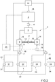
Figure 2 is a schematic view, with parts removed for clarity, of a tracked vehicle made according to the present invention and equipped with a hydraulic apparatus and the assembly of track-setting devices. - Referring to
Figures 1 and2 , reference numeral 1 indicates a tracked vehicle, as a whole, in particular a snow groomer, comprising: ahydraulic supply pump 2; ahydraulic supply pump 60; amain tiller 81 supplied by thehydraulic pump 60; ahydraulic apparatus 3 and an assembly of track-setting devices 4 coupled to thehydraulic pump 2 by means of thehydraulic apparatus 3. - In the accompanying figures, the
hydraulic apparatus 3 is mounted on a load-bearing structure of the tracked vehicle 1, but could also be mounted on a load-bearing structure of the assembly of track-setting devices 4. - The
hydraulic pump 2 is a hydraulic pump that is configured and is generally used for supplying a winch of the tracked vehicle 1. - Referring to
Figure 2 , thehydraulic apparatus 3 comprises: ahydraulic inlet 6 to receive an incompressible fluid; and ahydraulic outlet 7 and ahydraulic outlet 8 to release two flows of incompressible fluid having the same flow rate. - The
hydraulic apparatus 3 also comprises: ahydraulic coupling motor 9 having aninlet 10, anoutlet 11 and ashaft 12; and ahydraulic coupling motor 13 having aninlet 14, anoutlet 15 and ashaft 16. -
Hydraulic coupling motor 9 has the same technical specifications ashydraulic drive motor 13; in particular,hydraulic coupling motor 9 andhydraulic drive motor 13 are identical. - Furthermore, the
inlet 10 ofhydraulic coupling motor 9 and theinlet 14 ofhydraulic coupling motor 13 are connected toinlet 6 of thehydraulic apparatus 3. In other words,hydraulic coupling motor 9 andhydraulic coupling motor 13 are supplied with an inlet flow to thehydraulic apparatus 3 that derives fromhydraulic pump 2. In greater detail, thehydraulic apparatus 3 comprises aconnector 5 having three ports that connectinlet 6 withinlet 10 andinlet 14.Connector 5 is, by way of non-limitative example of the present invention, a tee connector. - Furthermore, the
shaft 12 ofhydraulic coupling motor 9 and theshaft 16 ofhydraulic coupling motor 13 are integrally connected to each other; in other words,shafts connection 17. - In this way, a flow rate of
fluid leaving outlet 11 ofhydraulic coupling motor 9 is the same as a flow rate offluid leaving outlet 15 ofhydraulic coupling motor 13. - Furthermore,
outlet 7 of thehydraulic apparatus 3 is connected to theoutlet 11 ofhydraulic coupling motor 9; in other words, the outlet flow fromoutlet 7 is supplied from theoutlet 11 ofhydraulic coupling motor 9. - Furthermore,
outlet 8 of thehydraulic apparatus 3 is connected to theoutlet 15 ofhydraulic coupling motor 13; in other words, the outlet flow fromoutlet 8 is supplied from theoutlet 15 ofhydraulic coupling motor 13. - Therefore, the
hydraulic apparatus 3 is configured such that a flow rate offluid leaving outlet 7 ofhydraulic apparatus 3 is the same as a flow rate offluid leaving outlet 8 ofhydraulic apparatus 3. - In other words, the
hydraulic apparatus 3 is able to supply two hydraulic appliances via a single hydraulic supply pump providing two identical flow rates, thehydraulic apparatus 3 consequently supplying two separate appliances with high qualitative parameters using a single hydraulic pump. - Referring to
Figure 2 , thehydraulic apparatus 3 comprises ahydraulic pressure sensor 18 coupled tooutlet 7 for detecting the pressure of the fluid atoutlet 7; and ahydraulic pressure sensor 19 coupled tooutlet 8 for detecting the pressure of the fluid atoutlet 8. - The
hydraulic pump 2 of the tracked vehicle 1 is a variable flow pump and supplies theinlet 6 of thehydraulic apparatus 3 with an incompressible fluid, for example oil. - The tracked vehicle 1 comprises a
control unit 20 coupled to the variable flowhydraulic pump 2 to control thehydraulic pump 2 and coupled topressure sensor 18 andpressure sensor 19. - The
control unit 20 receives the pressure values atoutlets hydraulic pump 2 based on the received pressures. - In greater detail, the
control unit 20 adjusts the flow of thehydraulic pump 2 so that one or both pressures at theoutlets - In greater detail, the
control unit 20 is configured to reduce the flow of thehydraulic pump 2 if at least one of the pressures atoutlets - In other words, during normal operation, the
control unit 20 regulates thehydraulic pump 2 so that it delivers its maximum flow and, in the case where it detects that at least one of the pressures at theoutlets hydraulic pump 2 with respect to the maximum flow to a first given value. - If the at least one pressure that was greater than the threshold value drops below the threshold value, the
control unit 20 keeps the flow at a first given value for a certain time interval. After the certain time interval has passed and the at least one pressure has remained below the threshold value, thecontrol unit 20 increases the flow of thehydraulic pump 2 to the maximum value. - Instead, if the at least one pressure that was greater than the threshold value still remains above the pressure threshold value, the
control unit 20 then further reduces the flow of thehydraulic pump 2 until the at least one pressure drops below the given pressure threshold value. -
Outlets - In greater detail, the assembly of track-setting devices 4 are configured for producing a classic style skiing trail and comprise a plurality of track-setting devices.
- Referring to
Figures 1 and2 , the assembly of track-setting devices 4 comprises a track-setting device 31, a track-setting device 32, a track-setting device 33 and a track-setting device 34. - Track-
setting device 31 comprises a tiller 41 supplied by ahydraulic drive motor 51. - In addition, track-
setting device 31 comprises a track-setting sledge 71 connected to tiller 41 so as to form tracks where the tiller 41 has worked the snow cover.
Track-setting device 32 comprises a tiller 42 supplied by ahydraulic drive motor 52. - In addition, track-
setting device 32 comprises a track-setting sledge 72 connected to tiller 42 so as to form tracks where the tiller 42 has worked the snow cover. - Track-
setting device 33 comprises a tiller 43 supplied by ahydraulic drive motor 53. - In addition, track-
setting device 33 comprises a track-setting sledge 73 connected to tiller 43 so as to form tracks where the tiller 43 has worked the snow cover.
Track-setting device 34 comprises atiller 44 supplied by ahydraulic drive motor 54. - In addition, track-
setting device 34 comprises a track-setting sledge 74 connected totiller 44 so as to form tracks where thetiller 44 has worked the snow cover. The tillers 41, 42, 43 and 44 are also called auxiliary tillers. - The
tillers 41, 42, 43 and 44 are arranged in alignment along an axis A. Axis A is transverse, preferably perpendicular, to a direction of forward movement D of the tracked vehicle 1.
Tiller 41 is adjacent to tiller 42.
Tiller 42 is placed between tiller 41 and tiller 43 along axis A.
Tiller 42 is placed between tiller 41 andtiller 44 along axis A.
Tiller 43 is placed between tiller 41 andtiller 44 along axis A.
Tiller 43 is placed between tiller 42 andtiller 44 along axis A.
Tiller 44 is adjacent to tiller 43. - Referring to
Figure 2 , the assembly of track-setting devices 4 comprises ahydraulic line 61 and ahydraulic line 62. -
Hydraulic line 61 connectshydraulic drive motor 51 withhydraulic drive motor 53. In consequence,hydraulic drive motor 51 andhydraulic drive motor 53 are connected in series. -
Hydraulic line 62 connectshydraulic drive motor 54 withhydraulic drive motor 52. In consequence,hydraulic drive motor 54 andhydraulic drive motor 52 are connected in series.
Thehydraulic apparatus 3 comprises a three-port connector 24. - In use,
hydraulic line 61 is connected tooutlet 7 of thehydraulic apparatus 3 upstream of thehydraulic drive motor 51. - In use,
hydraulic line 61 is connected to theconnector 24 of thehydraulic apparatus 3 downstream of thehydraulic drive motor 53. - In use,
hydraulic line 62 is connected tooutlet 8 of thehydraulic apparatus 3 upstream of thehydraulic drive motor 54. - In use,
hydraulic line 62 is connected to theconnector 24 of thehydraulic apparatus 3 downstream of thehydraulic drive motor 52. - The
hydraulic pump 2 comprises aninlet 25 that, in use, is connected toconnector 24. - In consequence, the
hydraulic pump 2, thehydraulic apparatus 3 and the assembly of track-setting devices 4 are connected to one another by a closed hydraulic circuit. - The hydraulic connection in series of pairs of hydraulic motors corresponding to non-adjacent auxiliary tillers provides the advantage of having smaller pressure differences between the pressures in
hydraulic lines - In other words, there are certain working conditions in which it is required to form a number of cross-country skiing trails in the snow cover that is less than the maximum number of cross-country skiing trails definable with the assembly of track-setting devices 4. In this case, a number of track-setting devices are positioned in contact with the snow cover and the remaining number of track-setting devices are raised from the snow cover and are not in contact with the snow cover. In certain circumstances, two adjacent cross-country skiing tracks are required and it is therefore necessary that two adjacent track-setting devices work, which could be two lateral track-setting devices, i.e. track-setting
devices devices devices devices - In all of the above-mentioned cases, thanks to the connection in series of pairs of non-adjacent hydraulic motors and thanks to the fact that the two hydraulic motors associated with the end track-setting devices are connected on two separate lines, the loads on each of the two
hydraulic lines hydraulic lines hydraulic lines hydraulic apparatus 3. - Furthermore, referring to
Figure 1 , themain tiller 81 extends for a dimension, preferably calculated along axis A, larger than each dimension of extension of theauxiliary tillers 41, 42, 43 and 44. - Preferably, the
main tiller 81 extends for a dimension calculated along axis A larger than the sum of the dimensions of extension calculated along axis A of theauxiliary tillers 41, 42, 43 and 44. - In other words, the
main tiller 81 is configured to work a larger extension of the snow cover than each extension of the snow cover worked by theauxiliary tillers 41, 42, 43 and 44, and preferably greater than the sum of the extensions of the snow cover worked by theauxiliary tillers 41, 42, 43 and 44. Furthermore, themain tiller 81 is arranged in front of theauxiliary tillers 41, 42, 43 and 44 according to the direction of forward movement D. In other words, themain tiller 81 is interposed between a load-bearing structure of the tracked vehicle 1 and the assembly of track-setting devices 4. - Finally, it is evident that modifications and variants can be made with regard to the invention thus described without departing from the scope of the appended claims.
Claims (15)
- An assembly of track-setting devices for producing a classic style skiing trail comprising: at least a first auxiliary tiller (41) and a second auxiliary tiller (44); characterised in that the first auxiliary tiller (41) has a first hydraulic drive motor (51) and the second auxiliary tiller (44) has a second hydraulic drive motor (54), wherein the assembly further comprises a hydraulic apparatus (3) comprising: a first inlet (6) for receiving a fluid; a first outlet (7) and a second outlet (8) for releasing two flows of fluid; a first hydraulic coupling motor (9) having a second inlet (10), a third outlet (11) and a first shaft (12); and a second hydraulic coupling motor (13) having a third inlet (14), a fourth outlet (15) and a second shaft (16); wherein the second inlet (10) and the third inlet (14) are connected to the first inlet (6), and the first shaft (12) and the second shaft (16) are integrally connected to each other, the third outlet (11) being connected to the first outlet (7), and the fourth outlet (15) being connected to the second outlet (8); wherein the first hydraulic drive motor (51) is supplied by the first outlet (7) and the second hydraulic drive motor (54) is supplied by the second outlet (8).
- The assembly of track-setting devices of claim 1, comprising a third auxiliary tiller (43) and a third hydraulic drive motor (53); the third hydraulic drive motor (53) being connected hydraulically in series with the first hydraulic drive motor (51); the first, the second and the third auxiliary tiller (41, 44, 43) being aligned along a first axis (A) transverse to a direction of forward movement (D); the third auxiliary tiller (43) being arranged between the first auxiliary tiller (41) and the second auxiliary tiller (44).
- The assembly of track-setting devices of claim 2, comprising a fourth auxiliary tiller (42) and a fourth hydraulic drive motor (52); the fourth hydraulic drive motor (52) being connected hydraulically in series to the second hydraulic motor (54); the fourth auxiliary tiller (42) being aligned along the first axis (A); the fourth auxiliary tiller (42) being arranged between the first auxiliary tiller (41) and the third auxiliary tiller (43).
- The assembly of track-setting devices of any one of claims 1 to 3, comprising a track-setting sledge (71, 72, 73, 74) for each auxiliary tiller (41, 42, 43, 44); the track-setting sledge (71, 72, 73, 74) being connected to the respective auxiliary tiller (41, 42, 43, 44) so as to form tracks where the auxiliary tiller (41, 42, 43, 44) has worked the snow cover.
- The assembly of track-setting devices of any one of claims 1 to 4, wherein the second inlet (10) and the third inlet (14) are connected to the first inlet (6) through a connector (5) having three ports, preferable a tee connector.
- The assembly of track-setting devices of any one of claims 1 to 5, wherein the first hydraulic coupling motor (9) is identical to as the second hydraulic coupling motor (13).
- The assembly of track-setting devices of any one of claims 1 to 6, the hydraulic apparatus comprising: a first hydraulic pressure sensor (18) coupled to the first outlet (7) for detecting a pressure of the fluid at the first outlet (7); and a second hydraulic pressure sensor (19) coupled to the second outlet (8) for detecting a pressure at the second outlet (8).
- A tracked vehicle, preferably a snow groomer, comprising a hydraulic apparatus (3) for supplying track-setting devices for producing a cross-country skiing trail; the hydraulic apparatus (3) comprising: a first inlet (6) for receiving a fluid; a first outlet (7) and a second outlet (8) for releasing two flows of fluid; a first hydraulic coupling motor (9) having a second inlet (10), a third outlet (11) and a first shaft (12); and a second hydraulic coupling motor (13) having a third inlet (14), a fourth outlet (15) and a second shaft (16); wherein the second inlet (10) and the third inlet (14) are connected to the first inlet (6), and the first shaft (12) and the second shaft (16) are integrally connected to each other, the third outlet (11) being connected to the first outlet (7), and the fourth outlet (15) being connected to the second outlet (8) ; the tracked vehicle comprising a hydraulic pump (2) that supplies the first inlet (6).
- The tracked vehicle of claim 8, wherein the second inlet (10) and the third inlet (14) are connected to the first inlet (6) through a connector (5) having three ports, preferable a tee connector.
- The tracked vehicle of any one of claims 8 to 9, wherein the first hydraulic coupling motor (9) is identical to the second hydraulic coupling motor (13).
- The tracked vehicle of any one of claims 8 to 10, The hydraulic apparatus comprising: a first hydraulic pressure sensor (18) coupled to the first outlet (7) for detecting a pressure of the fluid at the first outlet (7); and a second hydraulic pressure sensor (19) coupled to the second outlet (8) for detecting a pressure at the second outlet (8).
- A tracked vehicle comprising a variable flow hydraulic pump (2); and a hydraulic apparatus (3) comprising: a first inlet (6) for receiving a fluid; a first outlet (7) and a second outlet (8) for releasing two flows of fluid; a first hydraulic coupling motor (9) having a second inlet (10), a third outlet (11) and a first shaft (12); and a second hydraulic coupling motor (13) having a third inlet (14), a fourth outlet (15) and a second shaft (16); wherein the second inlet (10) and the third inlet (14) are connected to the first inlet (6), and the first shaft (12) and the second shaft (16) are integrally connected to each other, the third outlet (11) being connected to the first outlet (7), and the fourth outlet (15) being connected to the second outlet (8); the hydraulic apparatus comprising: a first hydraulic pressure sensor (18) coupled to the first outlet (7) for detecting a pressure of the fluid at the first outlet (7); and a second hydraulic pressure sensor (19) coupled to the second outlet (8) for detecting a pressure at the second outlet (8);the tracked vehicle comprising a control unit (20) coupled to the variable flow hydraulic pump (2) for controlling the hydraulic pump (2) and coupled to the first and to the second pressure sensor (18, 19); the control unit (20) controlling the variable flow hydraulic pump (2) based on the pressures detected by the first and by the second pressure sensor (18, 19).
- A tracked vehicle, preferably a snow groomer, comprising an assembly of track-setting devices (4) according to any one of claims 1 to 7; and a hydraulic pump (2) that supplies the first inlet (6).
- The tracked vehicle of claim 13, comprising a main tiller (81) that extends for a larger dimension than each dimension of extension of the auxiliary tillers (41, 42, 43, 44) and that is configured to work an extension of snow cover greater than each extension of snow cover worked by the auxiliary tillers (41, 42, 43, 44); the main tiller (81) being arranged in front of the auxiliary tillers (41, 42, 43, 44) in accordance with a direction of forward movement.
- Use of a hydraulic apparatus having two hydraulic coupling motors (9, 13) for connecting a hydraulic pump (2) of a tracked vehicle (1) to an assembly of track-setting devices (4) to form cross-country skiing trails; wherein the two hydraulic coupling motors (9, 13) have respective shafts (12, 16) integrally connected to each other; and wherein the outlets of the hydraulic coupling motors (11, 15) supply the assembly of track-setting devices (4).
Applications Claiming Priority (2)
| Application Number | Priority Date | Filing Date | Title |
|---|---|---|---|
| ITUA2016A002397A ITUA20162397A1 (en) | 2016-04-07 | 2016-04-07 | HYDRAULIC EQUIPMENT FOR FEEDING A GROUP OF TRACING DEVICES FOR A TRACKED VEHICLE; THE GROUP OF TRACING DEVICES AND THE TRACKED VEHICLE |
| PCT/IB2017/052022 WO2017175194A1 (en) | 2016-04-07 | 2017-04-07 | Hydraulic apparatus for supplying an assembly of track-setting devices for a tracked vehicle, the assembly of track-setting devices and the tracked vehicle |
Publications (2)
| Publication Number | Publication Date |
|---|---|
| EP3440263A1 EP3440263A1 (en) | 2019-02-13 |
| EP3440263B1 true EP3440263B1 (en) | 2020-03-11 |
Family
ID=56413771
Family Applications (1)
| Application Number | Title | Priority Date | Filing Date |
|---|---|---|---|
| EP17724901.8A Active EP3440263B1 (en) | 2016-04-07 | 2017-04-07 | Assembly of track-setting devices and tracked vehicle |
Country Status (6)
| Country | Link |
|---|---|
| US (1) | US10753056B2 (en) |
| EP (1) | EP3440263B1 (en) |
| CN (1) | CN107923134B (en) |
| IT (1) | ITUA20162397A1 (en) |
| RU (1) | RU2742066C2 (en) |
| WO (1) | WO2017175194A1 (en) |
Families Citing this family (3)
| Publication number | Priority date | Publication date | Assignee | Title |
|---|---|---|---|---|
| ITUA20162388A1 (en) * | 2016-04-07 | 2017-10-07 | Prinoth Spa | APPARATUS FOR REALIZING A SKI SLOPE TRACK |
| CN109011533B (en) * | 2018-07-10 | 2020-09-25 | 上海宝冶建设工业炉工程技术有限公司 | Track jet structure and track jet forming method |
| CN111636353B (en) * | 2020-05-26 | 2021-11-23 | 卫晓峰 | Snow field slide remold clearance and turn over throwing device with snowfield layering |
Family Cites Families (13)
| Publication number | Priority date | Publication date | Assignee | Title |
|---|---|---|---|---|
| US4122614A (en) * | 1977-03-28 | 1978-10-31 | Cheney Stanley O | Nordic ski track sled |
| SU950990A1 (en) * | 1980-12-25 | 1982-08-15 | Кировоградский Завод Тракторных Гидроагрегатов Им.Хху Съезда Кпсс | Controllable positive displacement drive |
| DE19754883C2 (en) * | 1997-12-10 | 2002-02-07 | Hyco Pacoma Gmbh | Hydraulic synchronous circuit with at least one master cylinder and at least one slave cylinder |
| ITBZ20010017A1 (en) * | 2001-03-30 | 2002-09-30 | Leitner Snow Gmbh S R L | MACHINE FOR THE PREPARATION OF THE SNOW SLOPES WITH ROTARY MOUNTED CUTTER. |
| DE10253412A1 (en) * | 2002-11-08 | 2004-05-27 | Kässbohrer Geländefahrzeug AG | Method for controlling a piste grooming vehicle and piste grooming vehicle |
| DE102005046914A1 (en) * | 2005-09-30 | 2007-04-05 | Bomag Gmbh | Snow surface preparation apparatus and method for controlling a hydraulic circuit between such equipment and a tractor |
| DE102007046696A1 (en) * | 2007-09-28 | 2009-04-09 | Liebherr-Werk Nenzing Gmbh | Hydraulic drive system |
| ITMI20072096A1 (en) * | 2007-10-30 | 2009-04-30 | Rolic Invest Sarl | CONNECTION DEVICE BETWEEN A BAPTIST VEHICLE AND AN EQUIPMENT FOR THE PREPARATION OF THE SNOWY SLOPE OF THE SKI SLOPES AND METHOD OF CONTROL USING THIS LINKING DEVICE |
| US8555635B2 (en) * | 2009-01-15 | 2013-10-15 | Hallite Seals Americas, Inc. | Hydraulic system for synchronizing a plurality of pistons and an associated method |
| IT1395088B1 (en) * | 2009-03-12 | 2012-09-05 | Rolic Invest Sarl | VEHICLE BAPTIST AND METHOD OF CONTROL OF THE SAME |
| IT1397194B1 (en) * | 2009-12-01 | 2013-01-04 | Rolic Invest Sarl | VEHICLE BAPTIST AND ITS CONTROL METHOD. |
| FR2956462B1 (en) | 2010-02-18 | 2012-05-18 | Poclain Hydraulics Ind | HYDRAULIC TRANSMISSION DEVICE IN WHICH THE MAIN PUMP CAN BE ACTUATED PERMANENTLY. |
| IT1403595B1 (en) * | 2010-12-21 | 2013-10-31 | Rolic Invest Sarl | METHOD FOR TRACING IN A SNOWY TRACK, IN PARTICULAR TO CREATE A SKI SLOPE, AND ITS TRACER DEVICE |
-
2016
- 2016-04-07 IT ITUA2016A002397A patent/ITUA20162397A1/en unknown
-
2017
- 2017-04-07 EP EP17724901.8A patent/EP3440263B1/en active Active
- 2017-04-07 CN CN201780002834.8A patent/CN107923134B/en active Active
- 2017-04-07 RU RU2018138944A patent/RU2742066C2/en active
- 2017-04-07 US US16/090,989 patent/US10753056B2/en active Active
- 2017-04-07 WO PCT/IB2017/052022 patent/WO2017175194A1/en not_active Ceased
Non-Patent Citations (1)
| Title |
|---|
| None * |
Also Published As
| Publication number | Publication date |
|---|---|
| EP3440263A1 (en) | 2019-02-13 |
| US10753056B2 (en) | 2020-08-25 |
| CA3020178A1 (en) | 2017-10-12 |
| RU2018138944A (en) | 2020-05-12 |
| RU2018138944A3 (en) | 2020-07-13 |
| CN107923134A (en) | 2018-04-17 |
| CN107923134B (en) | 2021-04-09 |
| US20190112769A1 (en) | 2019-04-18 |
| RU2742066C2 (en) | 2021-02-02 |
| ITUA20162397A1 (en) | 2017-10-07 |
| WO2017175194A1 (en) | 2017-10-12 |
Similar Documents
| Publication | Publication Date | Title |
|---|---|---|
| CN106930990B (en) | System for controlling the supply of hydraulic fluid to a work vehicle implement | |
| US10753056B2 (en) | Hydraulic apparatus for supplying an assembly of track-setting devices for a tracked vehicle, the assembly of track-setting devices and the tracked vehicle | |
| EP3012489B1 (en) | Hydraulic system for a vehicle | |
| US20070089391A1 (en) | Crop harvesting header with drive reversal | |
| CN107587548A (en) | The hydraulic circuit of construction machinery | |
| US20130312401A1 (en) | Pilot Pressure Supply System | |
| CN107060727A (en) | A kind of hydraulic gate TT&C system | |
| CN101994725A (en) | Hydraulic assembly | |
| EP4204281B1 (en) | Hydraulic steering device | |
| WO2017050674A1 (en) | Oil supply system of an automatic transmission or automated manual transmission in a powertrain | |
| EP2784223A2 (en) | Vehicle with attachment coupling and attachment for the same | |
| KR20070102573A (en) | drive | |
| CN101687464A (en) | Hydraulic drive vehicle | |
| CA3020178C (en) | Hydraulic apparatus for supplying an assembly of track-setting devices for a tracked vehicle, the assembly of track-setting devices and the tracked vehicle | |
| DE102006003414B3 (en) | Hydraulic circuit arrangement | |
| US9783051B2 (en) | Hydrostatic transmission system of a mobile machine traveling on a slope with a tilt | |
| WO2011067651A3 (en) | Snow groomer and relative control method | |
| DE102007057655A1 (en) | Travel drive for implements | |
| EP2686560B1 (en) | Auxiliary drive for working implements | |
| WO2016138565A1 (en) | Method and hydraulic system for mining operation | |
| EP2280196B1 (en) | Hydrostatic drive | |
| SE1550854A1 (en) | Agricultural implements and method of feeding hydraulic power to an agricultural implement | |
| EP2591931A1 (en) | Hydrostatic traction drive and vehicle with such a traction drive | |
| EP3236085A1 (en) | Amplifier valve for a closed-center-system working hydraulic system for an agricultural or civil engineering working machine | |
| CN103953594B (en) | A kind of running gear system and road wheel fluid power system thereof |
Legal Events
| Date | Code | Title | Description |
|---|---|---|---|
| STAA | Information on the status of an ep patent application or granted ep patent |
Free format text: STATUS: UNKNOWN |
|
| STAA | Information on the status of an ep patent application or granted ep patent |
Free format text: STATUS: THE INTERNATIONAL PUBLICATION HAS BEEN MADE |
|
| PUAI | Public reference made under article 153(3) epc to a published international application that has entered the european phase |
Free format text: ORIGINAL CODE: 0009012 |
|
| STAA | Information on the status of an ep patent application or granted ep patent |
Free format text: STATUS: REQUEST FOR EXAMINATION WAS MADE |
|
| 17P | Request for examination filed |
Effective date: 20181012 |
|
| AK | Designated contracting states |
Kind code of ref document: A1 Designated state(s): AL AT BE BG CH CY CZ DE DK EE ES FI FR GB GR HR HU IE IS IT LI LT LU LV MC MK MT NL NO PL PT RO RS SE SI SK SM TR |
|
| AX | Request for extension of the european patent |
Extension state: BA ME |
|
| DAV | Request for validation of the european patent (deleted) | ||
| DAX | Request for extension of the european patent (deleted) | ||
| GRAP | Despatch of communication of intention to grant a patent |
Free format text: ORIGINAL CODE: EPIDOSNIGR1 |
|
| STAA | Information on the status of an ep patent application or granted ep patent |
Free format text: STATUS: GRANT OF PATENT IS INTENDED |
|
| INTG | Intention to grant announced |
Effective date: 20191002 |
|
| GRAS | Grant fee paid |
Free format text: ORIGINAL CODE: EPIDOSNIGR3 |
|
| GRAA | (expected) grant |
Free format text: ORIGINAL CODE: 0009210 |
|
| STAA | Information on the status of an ep patent application or granted ep patent |
Free format text: STATUS: THE PATENT HAS BEEN GRANTED |
|
| AK | Designated contracting states |
Kind code of ref document: B1 Designated state(s): AL AT BE BG CH CY CZ DE DK EE ES FI FR GB GR HR HU IE IS IT LI LT LU LV MC MK MT NL NO PL PT RO RS SE SI SK SM TR |
|
| REG | Reference to a national code |
Ref country code: GB Ref legal event code: FG4D |
|
| REG | Reference to a national code |
Ref country code: CH Ref legal event code: EP |
|
| REG | Reference to a national code |
Ref country code: AT Ref legal event code: REF Ref document number: 1243280 Country of ref document: AT Kind code of ref document: T Effective date: 20200315 |
|
| REG | Reference to a national code |
Ref country code: DE Ref legal event code: R096 Ref document number: 602017012997 Country of ref document: DE |
|
| REG | Reference to a national code |
Ref country code: IE Ref legal event code: FG4D |
|
| REG | Reference to a national code |
Ref country code: CH Ref legal event code: NV Representative=s name: HEPP WENGER RYFFEL AG, CH |
|
| REG | Reference to a national code |
Ref country code: SE Ref legal event code: TRGR |
|
| REG | Reference to a national code |
Ref country code: NO Ref legal event code: T2 Effective date: 20200311 |
|
| PG25 | Lapsed in a contracting state [announced via postgrant information from national office to epo] |
Ref country code: RS Free format text: LAPSE BECAUSE OF FAILURE TO SUBMIT A TRANSLATION OF THE DESCRIPTION OR TO PAY THE FEE WITHIN THE PRESCRIBED TIME-LIMIT Effective date: 20200311 Ref country code: FI Free format text: LAPSE BECAUSE OF FAILURE TO SUBMIT A TRANSLATION OF THE DESCRIPTION OR TO PAY THE FEE WITHIN THE PRESCRIBED TIME-LIMIT Effective date: 20200311 |
|
| REG | Reference to a national code |
Ref country code: NL Ref legal event code: MP Effective date: 20200311 |
|
| PG25 | Lapsed in a contracting state [announced via postgrant information from national office to epo] |
Ref country code: GR Free format text: LAPSE BECAUSE OF FAILURE TO SUBMIT A TRANSLATION OF THE DESCRIPTION OR TO PAY THE FEE WITHIN THE PRESCRIBED TIME-LIMIT Effective date: 20200612 Ref country code: HR Free format text: LAPSE BECAUSE OF FAILURE TO SUBMIT A TRANSLATION OF THE DESCRIPTION OR TO PAY THE FEE WITHIN THE PRESCRIBED TIME-LIMIT Effective date: 20200311 Ref country code: LV Free format text: LAPSE BECAUSE OF FAILURE TO SUBMIT A TRANSLATION OF THE DESCRIPTION OR TO PAY THE FEE WITHIN THE PRESCRIBED TIME-LIMIT Effective date: 20200311 Ref country code: BG Free format text: LAPSE BECAUSE OF FAILURE TO SUBMIT A TRANSLATION OF THE DESCRIPTION OR TO PAY THE FEE WITHIN THE PRESCRIBED TIME-LIMIT Effective date: 20200611 |
|
| REG | Reference to a national code |
Ref country code: LT Ref legal event code: MG4D |
|
| PG25 | Lapsed in a contracting state [announced via postgrant information from national office to epo] |
Ref country code: NL Free format text: LAPSE BECAUSE OF FAILURE TO SUBMIT A TRANSLATION OF THE DESCRIPTION OR TO PAY THE FEE WITHIN THE PRESCRIBED TIME-LIMIT Effective date: 20200311 |
|
| PG25 | Lapsed in a contracting state [announced via postgrant information from national office to epo] |
Ref country code: EE Free format text: LAPSE BECAUSE OF FAILURE TO SUBMIT A TRANSLATION OF THE DESCRIPTION OR TO PAY THE FEE WITHIN THE PRESCRIBED TIME-LIMIT Effective date: 20200311 Ref country code: LT Free format text: LAPSE BECAUSE OF FAILURE TO SUBMIT A TRANSLATION OF THE DESCRIPTION OR TO PAY THE FEE WITHIN THE PRESCRIBED TIME-LIMIT Effective date: 20200311 Ref country code: CZ Free format text: LAPSE BECAUSE OF FAILURE TO SUBMIT A TRANSLATION OF THE DESCRIPTION OR TO PAY THE FEE WITHIN THE PRESCRIBED TIME-LIMIT Effective date: 20200311 Ref country code: RO Free format text: LAPSE BECAUSE OF FAILURE TO SUBMIT A TRANSLATION OF THE DESCRIPTION OR TO PAY THE FEE WITHIN THE PRESCRIBED TIME-LIMIT Effective date: 20200311 Ref country code: SK Free format text: LAPSE BECAUSE OF FAILURE TO SUBMIT A TRANSLATION OF THE DESCRIPTION OR TO PAY THE FEE WITHIN THE PRESCRIBED TIME-LIMIT Effective date: 20200311 Ref country code: SM Free format text: LAPSE BECAUSE OF FAILURE TO SUBMIT A TRANSLATION OF THE DESCRIPTION OR TO PAY THE FEE WITHIN THE PRESCRIBED TIME-LIMIT Effective date: 20200311 Ref country code: PT Free format text: LAPSE BECAUSE OF FAILURE TO SUBMIT A TRANSLATION OF THE DESCRIPTION OR TO PAY THE FEE WITHIN THE PRESCRIBED TIME-LIMIT Effective date: 20200805 Ref country code: IS Free format text: LAPSE BECAUSE OF FAILURE TO SUBMIT A TRANSLATION OF THE DESCRIPTION OR TO PAY THE FEE WITHIN THE PRESCRIBED TIME-LIMIT Effective date: 20200711 |
|
| REG | Reference to a national code |
Ref country code: AT Ref legal event code: UEP Ref document number: 1243280 Country of ref document: AT Kind code of ref document: T Effective date: 20200311 |
|
| REG | Reference to a national code |
Ref country code: DE Ref legal event code: R097 Ref document number: 602017012997 Country of ref document: DE |
|
| PG25 | Lapsed in a contracting state [announced via postgrant information from national office to epo] |
Ref country code: MC Free format text: LAPSE BECAUSE OF FAILURE TO SUBMIT A TRANSLATION OF THE DESCRIPTION OR TO PAY THE FEE WITHIN THE PRESCRIBED TIME-LIMIT Effective date: 20200311 |
|
| PLBE | No opposition filed within time limit |
Free format text: ORIGINAL CODE: 0009261 |
|
| STAA | Information on the status of an ep patent application or granted ep patent |
Free format text: STATUS: NO OPPOSITION FILED WITHIN TIME LIMIT |
|
| PG25 | Lapsed in a contracting state [announced via postgrant information from national office to epo] |
Ref country code: LU Free format text: LAPSE BECAUSE OF NON-PAYMENT OF DUE FEES Effective date: 20200407 Ref country code: ES Free format text: LAPSE BECAUSE OF FAILURE TO SUBMIT A TRANSLATION OF THE DESCRIPTION OR TO PAY THE FEE WITHIN THE PRESCRIBED TIME-LIMIT Effective date: 20200311 Ref country code: DK Free format text: LAPSE BECAUSE OF FAILURE TO SUBMIT A TRANSLATION OF THE DESCRIPTION OR TO PAY THE FEE WITHIN THE PRESCRIBED TIME-LIMIT Effective date: 20200311 |
|
| REG | Reference to a national code |
Ref country code: BE Ref legal event code: MM Effective date: 20200430 |
|
| 26N | No opposition filed |
Effective date: 20201214 |
|
| PG25 | Lapsed in a contracting state [announced via postgrant information from national office to epo] |
Ref country code: BE Free format text: LAPSE BECAUSE OF NON-PAYMENT OF DUE FEES Effective date: 20200430 Ref country code: SI Free format text: LAPSE BECAUSE OF FAILURE TO SUBMIT A TRANSLATION OF THE DESCRIPTION OR TO PAY THE FEE WITHIN THE PRESCRIBED TIME-LIMIT Effective date: 20200311 Ref country code: PL Free format text: LAPSE BECAUSE OF FAILURE TO SUBMIT A TRANSLATION OF THE DESCRIPTION OR TO PAY THE FEE WITHIN THE PRESCRIBED TIME-LIMIT Effective date: 20200311 |
|
| PG25 | Lapsed in a contracting state [announced via postgrant information from national office to epo] |
Ref country code: IE Free format text: LAPSE BECAUSE OF NON-PAYMENT OF DUE FEES Effective date: 20200407 |
|
| GBPC | Gb: european patent ceased through non-payment of renewal fee |
Effective date: 20210407 |
|
| PG25 | Lapsed in a contracting state [announced via postgrant information from national office to epo] |
Ref country code: GB Free format text: LAPSE BECAUSE OF NON-PAYMENT OF DUE FEES Effective date: 20210407 |
|
| PG25 | Lapsed in a contracting state [announced via postgrant information from national office to epo] |
Ref country code: TR Free format text: LAPSE BECAUSE OF FAILURE TO SUBMIT A TRANSLATION OF THE DESCRIPTION OR TO PAY THE FEE WITHIN THE PRESCRIBED TIME-LIMIT Effective date: 20200311 Ref country code: MT Free format text: LAPSE BECAUSE OF FAILURE TO SUBMIT A TRANSLATION OF THE DESCRIPTION OR TO PAY THE FEE WITHIN THE PRESCRIBED TIME-LIMIT Effective date: 20200311 Ref country code: CY Free format text: LAPSE BECAUSE OF FAILURE TO SUBMIT A TRANSLATION OF THE DESCRIPTION OR TO PAY THE FEE WITHIN THE PRESCRIBED TIME-LIMIT Effective date: 20200311 |
|
| PG25 | Lapsed in a contracting state [announced via postgrant information from national office to epo] |
Ref country code: MK Free format text: LAPSE BECAUSE OF FAILURE TO SUBMIT A TRANSLATION OF THE DESCRIPTION OR TO PAY THE FEE WITHIN THE PRESCRIBED TIME-LIMIT Effective date: 20200311 Ref country code: AL Free format text: LAPSE BECAUSE OF FAILURE TO SUBMIT A TRANSLATION OF THE DESCRIPTION OR TO PAY THE FEE WITHIN THE PRESCRIBED TIME-LIMIT Effective date: 20200311 |
|
| P01 | Opt-out of the competence of the unified patent court (upc) registered |
Effective date: 20230518 |
|
| PGFP | Annual fee paid to national office [announced via postgrant information from national office to epo] |
Ref country code: SE Payment date: 20250311 Year of fee payment: 9 |
|
| PGFP | Annual fee paid to national office [announced via postgrant information from national office to epo] |
Ref country code: DE Payment date: 20250428 Year of fee payment: 9 |
|
| PGFP | Annual fee paid to national office [announced via postgrant information from national office to epo] |
Ref country code: NO Payment date: 20250422 Year of fee payment: 9 |
|
| PGFP | Annual fee paid to national office [announced via postgrant information from national office to epo] |
Ref country code: IT Payment date: 20250404 Year of fee payment: 9 |
|
| PGFP | Annual fee paid to national office [announced via postgrant information from national office to epo] |
Ref country code: FR Payment date: 20250424 Year of fee payment: 9 |
|
| PGFP | Annual fee paid to national office [announced via postgrant information from national office to epo] |
Ref country code: CH Payment date: 20250501 Year of fee payment: 9 |
|
| PGFP | Annual fee paid to national office [announced via postgrant information from national office to epo] |
Ref country code: AT Payment date: 20250417 Year of fee payment: 9 |
|
| REG | Reference to a national code |
Ref country code: CH Ref legal event code: U11 Free format text: ST27 STATUS EVENT CODE: U-0-0-U10-U11 (AS PROVIDED BY THE NATIONAL OFFICE) Effective date: 20260501 |