EP3439437A2 - Light system and method of powering the same - Google Patents
Light system and method of powering the same Download PDFInfo
- Publication number
- EP3439437A2 EP3439437A2 EP18186628.6A EP18186628A EP3439437A2 EP 3439437 A2 EP3439437 A2 EP 3439437A2 EP 18186628 A EP18186628 A EP 18186628A EP 3439437 A2 EP3439437 A2 EP 3439437A2
- Authority
- EP
- European Patent Office
- Prior art keywords
- light
- rechargeable battery
- tower
- power
- light tower
- Prior art date
- Legal status (The legal status is an assumption and is not a legal conclusion. Google has not performed a legal analysis and makes no representation as to the accuracy of the status listed.)
- Granted
Links
Images

Classifications
-
- H—ELECTRICITY
- H02—GENERATION; CONVERSION OR DISTRIBUTION OF ELECTRIC POWER
- H02J—ELECTRIC POWER NETWORKS; CIRCUIT ARRANGEMENTS OR SYSTEMS FOR SUPPLYING OR DISTRIBUTING ELECTRIC POWER; SYSTEMS FOR STORING ELECTRIC ENERGY
- H02J7/00—Circuit arrangements for charging or discharging batteries or for supplying loads from batteries
- H02J7/14—Circuit arrangements for charging or discharging batteries or for supplying loads from batteries for charging batteries from dynamo-electric generators driven at varying speed, e.g. on vehicle
- H02J7/1423—Circuit arrangements for charging or discharging batteries or for supplying loads from batteries for charging batteries from dynamo-electric generators driven at varying speed, e.g. on vehicle with multiple batteries
-
- F—MECHANICAL ENGINEERING; LIGHTING; HEATING; WEAPONS; BLASTING
- F21—LIGHTING
- F21L—LIGHTING DEVICES OR SYSTEMS THEREOF, BEING PORTABLE OR SPECIALLY ADAPTED FOR TRANSPORTATION
- F21L4/00—Electric lighting devices with self-contained electric batteries or cells
- F21L4/08—Electric lighting devices with self-contained electric batteries or cells characterised by means for in situ recharging of the batteries or cells
-
- H—ELECTRICITY
- H05—ELECTRIC TECHNIQUES NOT OTHERWISE PROVIDED FOR
- H05B—ELECTRIC HEATING; ELECTRIC LIGHT SOURCES NOT OTHERWISE PROVIDED FOR; CIRCUIT ARRANGEMENTS FOR ELECTRIC LIGHT SOURCES, IN GENERAL
- H05B47/00—Circuit arrangements for operating light sources in general, i.e. where the type of light source is not relevant
- H05B47/10—Controlling the light source
- H05B47/175—Controlling the light source by remote control
- H05B47/185—Controlling the light source by remote control via power line carrier transmission
-
- H—ELECTRICITY
- H05—ELECTRIC TECHNIQUES NOT OTHERWISE PROVIDED FOR
- H05B—ELECTRIC HEATING; ELECTRIC LIGHT SOURCES NOT OTHERWISE PROVIDED FOR; CIRCUIT ARRANGEMENTS FOR ELECTRIC LIGHT SOURCES, IN GENERAL
- H05B47/00—Circuit arrangements for operating light sources in general, i.e. where the type of light source is not relevant
- H05B47/10—Controlling the light source
- H05B47/175—Controlling the light source by remote control
- H05B47/19—Controlling the light source by remote control via wireless transmission
-
- H—ELECTRICITY
- H05—ELECTRIC TECHNIQUES NOT OTHERWISE PROVIDED FOR
- H05B—ELECTRIC HEATING; ELECTRIC LIGHT SOURCES NOT OTHERWISE PROVIDED FOR; CIRCUIT ARRANGEMENTS FOR ELECTRIC LIGHT SOURCES, IN GENERAL
- H05B47/00—Circuit arrangements for operating light sources in general, i.e. where the type of light source is not relevant
- H05B47/10—Controlling the light source
- H05B47/175—Controlling the light source by remote control
- H05B47/196—Controlling the light source by remote control characterised by user interface arrangements
- H05B47/1965—Controlling the light source by remote control characterised by user interface arrangements using handheld communication devices
-
- F—MECHANICAL ENGINEERING; LIGHTING; HEATING; WEAPONS; BLASTING
- F21—LIGHTING
- F21V—FUNCTIONAL FEATURES OR DETAILS OF LIGHTING DEVICES OR SYSTEMS THEREOF; STRUCTURAL COMBINATIONS OF LIGHTING DEVICES WITH OTHER ARTICLES, NOT OTHERWISE PROVIDED FOR
- F21V21/00—Supporting, suspending, or attaching arrangements for lighting devices; Hand grips
- F21V21/14—Adjustable mountings
- F21V21/22—Adjustable mountings telescopic
-
- F—MECHANICAL ENGINEERING; LIGHTING; HEATING; WEAPONS; BLASTING
- F21—LIGHTING
- F21V—FUNCTIONAL FEATURES OR DETAILS OF LIGHTING DEVICES OR SYSTEMS THEREOF; STRUCTURAL COMBINATIONS OF LIGHTING DEVICES WITH OTHER ARTICLES, NOT OTHERWISE PROVIDED FOR
- F21V23/00—Arrangement of electric circuit elements in or on lighting devices
- F21V23/02—Arrangement of electric circuit elements in or on lighting devices the elements being transformers, impedances or power supply units, e.g. a transformer with a rectifier
- F21V23/023—Power supplies in a casing
Definitions
- the present disclosure relates to a light system, and more particularly to a light system with networked rechargeable batteries and a separate power source.
- a light system includes a plurality of light towers having a first light tower and a second light tower.
- Each of the first light tower and the second light tower include a light source operable to illuminate an area adjacent the respective one of the plurality of light towers, a rechargeable battery operable to provide electrical power to the light source, and a control system programmed to control the flow of power to and from the rechargeable battery.
- the light system further includes a power/network cord electrically connecting the first light tower to the second light tower, a power source selectively operable to provide electrical power, and a power recharge cord arranged to electrically connect the first light tower to the power source.
- the power recharge cord is operable to provide electrical power from the power source to the first light tower and from the first light tower to the second light tower via the power/network cord.
- Each control system is programmed to selectively activate the power source to initiate a recharge cycle for the respective rechargeable battery.
- a light system includes a plurality of individual and separate light towers each spaced apart from one another.
- Each of the plurality of light towers includes a light source operable to illuminate an area adjacent the respective light tower, a rechargeable battery operable to provide electrical power to the light source, a control system programmed to control the flow of power to and from the rechargeable battery, and an enclosure for housing the rechargeable battery, the battery charger, and the control system.
- the light system further includes a power source separate and remote from each of the plurality of light towers.
- the power source includes an electrical generator and a controller. The controller is operable to selectively operate the electrical generator to generate a supply of electrical power.
- a method of powering a light source of a first light tower and a light source of a second light tower includes positioning the first light tower, positioning the second light tower relative to the first light tower, and directing power from a first rechargeable battery to the light source of the first light tower and from a second rechargeable battery to the light source of the second light tower.
- the method also includes electrically connecting the first light tower and the second light tower, analyzing a charge level of the first rechargeable battery and the second rechargeable battery with a control system, and powering the light source of the second light tower with the first rechargeable battery in response to the charge level of the second rechargeable battery falling below a predetermined level.
- a light system 10 includes a first light tower 12, a second light tower 14, and a power source 16.
- the light system 10 may include additional light towers (i.e., one or more additional light towers), as designated by reference numeral 18.
- Each light tower 12, 14, 18 includes a light source 20 supported on a first end of a vertical post 22 at a height above the ground to illuminate an area around the respective light tower 12, 14, 18.
- the light source 20 may be one or more light emitting diodes (LEDs), metal-halide bulbs, incandescent bulbs, halogen bulbs, or any other suitable light source.
- the vertical post 22 is attached at a second end (opposite the first end) to an enclosure 24 and is preferably extendable and retractable to position the light source 20 at a desired height above the enclosure 24.
- the enclosure 24 is supported on and movable relative to the ground surface to allow repositioning of the light tower 12, 14, 18 and more particularly to allow repositioning of each light tower 12, 14, 18 relative to each other.
- the enclosure 24 houses a rechargeable battery 26 for the light source 20 and a control system 28.
- the rechargeable battery 26 is electrically connected to the light source 20 to selectively power the light source 20 when actuated.
- the rechargeable battery 26 is further electrically connected to the power source 16 to permit recharging of the rechargeable battery 26 via the power source 16.
- the control system 28 provides signals to the rechargeable battery 26 to control when the rechargeable battery 26 powers the light 20 and when the rechargeable battery 26 is recharged via the power source 16.
- the battery 26 can be manufactured using any suitable chemistry with lithium ion being preferred.
- the power source 16 includes an electrical generator 32 (such as a diesel powered electrical generator) and a controller 34.
- the electrical generator 32 converts mechanical input into electrical output to provide electrical power to the light towers 12, 14, 18.
- the controller 34 sends electrical signals to the generator 32 to control when the generator 32 is actuated to provide power to the rechargeable batteries 26.
- the power source 16 is electrically connected to the first light tower 12 via a power recharge cord 36 that extends from the power source 16 to an electrical inlet port 38 in the first light tower 12.
- the power recharge cord 36 is configured to relay electrical power from the power source 16 to the first light tower 12 and may additionally relay data between the controller 34 and the control systems 28.
- the power source 16 is distinct from each of the light towers 12, 14, 18 and is only connected to the light towers 12, 14, 18 via the power recharge cord 36 (attached to the first light tower 12).
- the separation of the power source 16 and the light towers 12, 14, 18 permits placement of the power source 16 at a location away from the light towers 12, 14, 18 such that the noise generated by the power source 16 can be minimized adjacent the light towers 12, 14, 18.
- the first light tower 12 is electrically connected to the second light tower 14 via a power/network cord 40. More specifically, an electrical outlet port 42 of the first light tower 12 is electrically connected to the electrical inlet port 38 of the second light tower 14 via the power/network cord.
- the second light tower 14 is electrically connected to the additional light towers 18 via another power/network cord 40.
- Each power/network cord 40 is configured to relay electrical power and data (e.g., battery charge level) between the light towers 12, 14, 18.
- each of the light towers 12, 14, 18 is connected in parallel with the power source 16 to assure that the full voltage is applied to each battery 26 during recharging.
- the light system 10 further includes a wireless transceiver 50.
- the wireless transceiver 50 is programmed to communicate with the control systems 28 of the light towers 12, 14, 18 and with the controller 34 of the power source 16.
- the wireless transceiver 50 further communicates with a portable electronic device 52 (e.g., a smartphone, laptop computer, tablet, etc.) and provides the portable electronic device with a signal when the charge level on one or more of the rechargeable batteries is low. Further, an operator is able to use the portable electronic device 52 as an input device to provide instruction to the control systems 28 and controller 34.
- a portable electronic device 52 e.g., a smartphone, laptop computer, tablet, etc.
- the power source 16 is activated to charge the rechargeable batteries 26.
- the power source 16 may be activated directly by operator input to a user interface of the power source 16.
- the operator may actuate a switch, button, or other input on the power source 16, which in turn provides an input signal to the controller 34.
- the operator may provide an input to the portable electronic device 52.
- the portable electronic device 52 wirelessly sends a signal to the controller 34. Whether from the user interface or from the portable electronic device 52, the signal to the controller 34 prompts the controller 34 to activate the power source 16.
- the power source 16 may be activated only at predetermined times.
- the power source 16 can be controlled to automatically activate at a specific time or at a time within a specified range. For example, in order to avoid the noise generated by the power source 16 in a business environment, the power source 16 may be automatically activated only outside of business hours. Alternatively, in a residential environment, the power source 16 may be automatically activated only outside of nighttime hours. Further still, in the environment of a sporting event, the power source 16 may be automatically activated only outside of the hours of play.
- the power source 16 may be activated in response to inputs provided from the control systems 28 of the light towers 12, 14, 18 to the controller 34.
- a predetermined threshold value e.g. 50%, 25%, 10%, or 5% charge remaining, 60, 30, 20, 10, or 5 minutes of continuous output remaining, etc.
- the respective control system 28 sends a signal to the controller 34, alerting the controller of the low battery level, and prompting the controller 34 to activate the power source 16.
- the power source 16 charges the rechargeable batteries 26 of the light towers 12, 14, 18.
- the controller 34 communicates with the respective control systems 28 to charge only the batteries 26 below the predetermined threshold value, or below a second threshold, greater than the first threshold.
- the second threshold may be, for example, fully charged.
- the controller 34 can control a switch or a breaker to separate particular paths to batteries as desired. Thus, not all batteries 26 need to be simultaneously charged as the switches or breakers can be arranged to isolate even a single battery 26 if desired.
- the light towers 12, 14, 18 are programmed to selectively share power from the respective rechargeable batteries 26.
- the power source 16 is initially activated to recharge all of the batteries 26. Electrical power from the generator 32 is provided through the electrical inlet port 38 of the first light tower 12 and to the rechargeable battery 26 of the first light tower. The rechargeable battery 26 of the second light tower 14 is charged via the generator 32, through the first light tower 12 and the power/network cord 40 physically connecting the electrical outlet port 42 of the first light tower 12 and the electrical inlet port 38 of the second light tower 14.
- the control systems 28 and the controller 34 communicate via electrical signals to monitor and compare the charge level of the batteries 26.
- the control systems 28 wait a predetermined amount of time (e.g., 30 minutes, 5 minutes, 30 seconds, 5 seconds, etc.) before re-measuring the charge level of the respective batteries 26, thereby following a monitoring loop until one of the batteries drops below the threshold value.
- a predetermined amount of time e.g., 30 minutes, 5 minutes, 30 seconds, 5 seconds, etc.
- the second rechargeable battery 26 shares power with the first light tower 12 via the power/network cord 40 in a power sharing mode.
- the light source 20 of both light towers 12, 14 is powered or at least partially powered by the rechargeable battery of the second light tower 14.
- the battery 26 of the second light tower 14 powers only the light source 20 of the first light tower 12. Even when power sharing, the control systems 28 continue to monitor the charge level of the batteries 26. Once both batteries 26 are below the threshold value, the control systems 28 instruct the controller 34 to activate the power source 16 to recharge both batteries 26 in a recharge mode.
- the first rechargeable battery 26 shares power with the second light tower 14 via the power/network cord 40.
- the light source 20 of both light towers 12, 14 is powered by the rechargeable battery of the first light tower 12 in a power sharing mode.
- the control systems 28 instruct the controller 34 to actuate the power source 16 to recharge both batteries 26 in a recharge mode.
- FIG. 2 illustrates a process that may be performed free of user input. Alternatively, it may be desirable to have operator input to review battery charge levels and verify process changes before they occur.
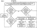
- FIG. 3 illustrates a process similar to FIG. 2 , with additional steps of verification.
- the power source 16 is initially actuated to recharge all of the batteries 26.
- Electrical power from the generator 32 is provided through the electrical inlet port 38 of the first light tower 12 and to the rechargeable battery 26 of the first light tower.
- the rechargeable battery 26 of the second light tower 14 is charged via the generator 32, through the first light tower 12 and the power/network cord 40 physically connecting the electrical outlet port 42 of the first light tower 12 and the electrical inlet port 38 of the second light tower 14.
- the control systems 28 and the controller 34 monitor the charge level of the batteries 26.
- control systems 28 wait the predetermined amount of time before re-measuring the charge level of the respective batteries 26, thereby following the monitoring loop discussed above with respect to FIG. 2 .
- the control system 28 sends a signal to the wireless transceiver 50.
- the wireless transceiver 50 sends an alert to the portable electronic device 52. The operator is able to review the charge level of both batteries 26 and decide, via the portable electronic device 52, whether the second rechargeable battery 26 should share power with the first light tower 12.
- the operator may decide to turn off the first light tower 12, actuate the power source 16 to recharge the batteries 26, or may decide to allow the first rechargeable battery 26 to continue powering the first light tower 12. For example, if the operator notes that the charge level of the second rechargeable battery 26 is nearing the threshold value (and power sharing would only last a short duration), the operator may bypass the power sharing mode (as designated by direction A1), and instead recharge the batteries 26 with the power source 16 (as designated by direction B1).
- the control system 28 sends a signal to the wireless transceiver 50.
- the wireless transceiver sends an alert to the portable electronic device 52. The operator is able to review the charge level of both batteries 26 and decide, via the portable electronic device 52, whether the first rechargeable battery 26 should share power with the second light tower 14.
- the operator may decide to turn off the second light tower 14, actuate the power source 16 to recharge the batteries 26, or may decide to allow the second rechargeable battery 26 to continue powering the second light tower 14. For example, if the operator notes that the charge level of the first rechargeable battery 26 is nearing the threshold value, the operator may bypass the power sharing mode (as designated by direction A2), and instead recharge the batteries 26 with the power source 16 (as designated by direction B2).
- the control systems 28 instruct the controller 34 to actuate the power source 16 to recharge both batteries 26.
- the operator may receive a prompt to activate the power source 16 via the portable electronic device 52, or a prompt on the portable electronic device 52 to manually activate the power source 16.
- FIGS. 2-3 are directed towards a light system including two light towers 12, 14, the concept of power sharing can be applied to the additional light towers 18 as well.
- each of the batteries 26 is monitored and three modes of power sharing exist. In a first mode, each battery 26 powers its respective light source 20. In a second mode, one of the batteries 26 provides power to two light sources and another battery 26 provides power to the third light source 20. In a third mode, one of the batteries 26 provides power to all of the light sources 20.
Landscapes
- Engineering & Computer Science (AREA)
- Computer Networks & Wireless Communication (AREA)
- Power Engineering (AREA)
- General Engineering & Computer Science (AREA)
- Circuit Arrangement For Electric Light Sources In General (AREA)
- Charge And Discharge Circuits For Batteries Or The Like (AREA)
- Non-Portable Lighting Devices Or Systems Thereof (AREA)
Abstract
Description
- The present disclosure relates to a light system, and more particularly to a light system with networked rechargeable batteries and a separate power source.
- A light system includes a plurality of light towers having a first light tower and a second light tower. Each of the first light tower and the second light tower include a light source operable to illuminate an area adjacent the respective one of the plurality of light towers, a rechargeable battery operable to provide electrical power to the light source, and a control system programmed to control the flow of power to and from the rechargeable battery. The light system further includes a power/network cord electrically connecting the first light tower to the second light tower, a power source selectively operable to provide electrical power, and a power recharge cord arranged to electrically connect the first light tower to the power source. The power recharge cord is operable to provide electrical power from the power source to the first light tower and from the first light tower to the second light tower via the power/network cord. Each control system is programmed to selectively activate the power source to initiate a recharge cycle for the respective rechargeable battery.
- A light system includes a plurality of individual and separate light towers each spaced apart from one another. Each of the plurality of light towers includes a light source operable to illuminate an area adjacent the respective light tower, a rechargeable battery operable to provide electrical power to the light source, a control system programmed to control the flow of power to and from the rechargeable battery, and an enclosure for housing the rechargeable battery, the battery charger, and the control system. The light system further includes a power source separate and remote from each of the plurality of light towers. The power source includes an electrical generator and a controller. The controller is operable to selectively operate the electrical generator to generate a supply of electrical power.
- A method of powering a light source of a first light tower and a light source of a second light tower includes positioning the first light tower, positioning the second light tower relative to the first light tower, and directing power from a first rechargeable battery to the light source of the first light tower and from a second rechargeable battery to the light source of the second light tower. The method also includes electrically connecting the first light tower and the second light tower, analyzing a charge level of the first rechargeable battery and the second rechargeable battery with a control system, and powering the light source of the second light tower with the first rechargeable battery in response to the charge level of the second rechargeable battery falling below a predetermined level.
- Other features and aspects of the disclosure will become apparent by consideration of the following detailed description and accompanying drawings.
-
-
FIG. 1 is a schematic representation of a light system. -
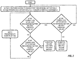
FIG. 2 is a flow diagram illustrating a method of powering the light system. -
FIG. 3 is a flow diagram illustrating a further method of powering the lights system. - Before any embodiments of the disclosure are explained in detail, it is to be understood that the disclosure is not limited in its application to the details of construction and the arrangement of components set forth in the following description or illustrated in the following drawings. The disclosure is capable of supporting other embodiments and of being practiced or of being carried out in various ways. Also, it is to be understood that the phraseology and terminology used herein is for the purpose of description and should not be regarded as limiting.
- As shown in
FIG. 1 , alight system 10 includes afirst light tower 12, asecond light tower 14, and apower source 16. Thelight system 10 may include additional light towers (i.e., one or more additional light towers), as designated byreference numeral 18. Eachlight tower light source 20 supported on a first end of avertical post 22 at a height above the ground to illuminate an area around therespective light tower light source 20 may be one or more light emitting diodes (LEDs), metal-halide bulbs, incandescent bulbs, halogen bulbs, or any other suitable light source. Thevertical post 22 is attached at a second end (opposite the first end) to anenclosure 24 and is preferably extendable and retractable to position thelight source 20 at a desired height above theenclosure 24. - The
enclosure 24 is supported on and movable relative to the ground surface to allow repositioning of thelight tower light tower enclosure 24 houses arechargeable battery 26 for thelight source 20 and acontrol system 28. Therechargeable battery 26 is electrically connected to thelight source 20 to selectively power thelight source 20 when actuated. Therechargeable battery 26 is further electrically connected to thepower source 16 to permit recharging of therechargeable battery 26 via thepower source 16. Thecontrol system 28 provides signals to therechargeable battery 26 to control when therechargeable battery 26 powers thelight 20 and when therechargeable battery 26 is recharged via thepower source 16. Thebattery 26 can be manufactured using any suitable chemistry with lithium ion being preferred. - The
power source 16, as shown, includes an electrical generator 32 (such as a diesel powered electrical generator) and acontroller 34. Theelectrical generator 32 converts mechanical input into electrical output to provide electrical power to thelight towers controller 34 sends electrical signals to thegenerator 32 to control when thegenerator 32 is actuated to provide power to therechargeable batteries 26. Thepower source 16 is electrically connected to thefirst light tower 12 via apower recharge cord 36 that extends from thepower source 16 to anelectrical inlet port 38 in thefirst light tower 12. Thepower recharge cord 36 is configured to relay electrical power from thepower source 16 to thefirst light tower 12 and may additionally relay data between thecontroller 34 and thecontrol systems 28. - The
power source 16 is distinct from each of thelight towers light towers power source 16 and thelight towers power source 16 at a location away from thelight towers power source 16 can be minimized adjacent thelight towers - The
first light tower 12 is electrically connected to thesecond light tower 14 via a power/network cord 40. More specifically, anelectrical outlet port 42 of thefirst light tower 12 is electrically connected to theelectrical inlet port 38 of thesecond light tower 14 via the power/network cord. Thesecond light tower 14 is electrically connected to theadditional light towers 18 via another power/network cord 40. Each power/network cord 40 is configured to relay electrical power and data (e.g., battery charge level) between thelight towers light towers power source 16 to assure that the full voltage is applied to eachbattery 26 during recharging. - The
light system 10 further includes awireless transceiver 50. Thewireless transceiver 50 is programmed to communicate with thecontrol systems 28 of thelight towers controller 34 of thepower source 16. Thewireless transceiver 50 further communicates with a portable electronic device 52 (e.g., a smartphone, laptop computer, tablet, etc.) and provides the portable electronic device with a signal when the charge level on one or more of the rechargeable batteries is low. Further, an operator is able to use the portableelectronic device 52 as an input device to provide instruction to thecontrol systems 28 andcontroller 34. - In normal operation, the
power source 16 is activated to charge therechargeable batteries 26. Thepower source 16 may be activated directly by operator input to a user interface of thepower source 16. For example, the operator may actuate a switch, button, or other input on thepower source 16, which in turn provides an input signal to thecontroller 34. Alternatively, the operator may provide an input to the portableelectronic device 52. The portableelectronic device 52 wirelessly sends a signal to thecontroller 34. Whether from the user interface or from the portableelectronic device 52, the signal to thecontroller 34 prompts thecontroller 34 to activate thepower source 16. - As an additional alternative, the
power source 16 may be activated only at predetermined times. Thepower source 16 can be controlled to automatically activate at a specific time or at a time within a specified range. For example, in order to avoid the noise generated by thepower source 16 in a business environment, thepower source 16 may be automatically activated only outside of business hours. Alternatively, in a residential environment, thepower source 16 may be automatically activated only outside of nighttime hours. Further still, in the environment of a sporting event, thepower source 16 may be automatically activated only outside of the hours of play. - As a further alternative, the
power source 16 may be activated in response to inputs provided from thecontrol systems 28 of thelight towers controller 34. When the charge level of arechargeable battery 26 drops below a predetermined threshold value (e.g., 50%, 25%, 10%, or 5% charge remaining, 60, 30, 20, 10, or 5 minutes of continuous output remaining, etc.), therespective control system 28 sends a signal to thecontroller 34, alerting the controller of the low battery level, and prompting thecontroller 34 to activate thepower source 16. - Once activated, the
power source 16 charges therechargeable batteries 26 of thelight towers controller 34 communicates with therespective control systems 28 to charge only thebatteries 26 below the predetermined threshold value, or below a second threshold, greater than the first threshold. The second threshold may be, for example, fully charged. Thecontroller 34 can control a switch or a breaker to separate particular paths to batteries as desired. Thus, not allbatteries 26 need to be simultaneously charged as the switches or breakers can be arranged to isolate even asingle battery 26 if desired. - In order to postpone use of the
power source 16 and likewise defer the noise produced by thegenerator 32 when it is activated, thelight towers rechargeable batteries 26. As shown in the flow diagram ofFIG. 2 , which illustrates a scenario involving twolight towers power source 16 is initially activated to recharge all of thebatteries 26. Electrical power from thegenerator 32 is provided through theelectrical inlet port 38 of thefirst light tower 12 and to therechargeable battery 26 of the first light tower. Therechargeable battery 26 of thesecond light tower 14 is charged via thegenerator 32, through thefirst light tower 12 and the power/network cord 40 physically connecting theelectrical outlet port 42 of thefirst light tower 12 and theelectrical inlet port 38 of thesecond light tower 14. Once thebatteries 26 are recharged or thepower source 16 is manually deactivated, thecontrol systems 28 and thecontroller 34 communicate via electrical signals to monitor and compare the charge level of thebatteries 26. - If the charge levels of both
batteries 26 are measured to be above the threshold value, thecontrol systems 28 wait a predetermined amount of time (e.g., 30 minutes, 5 minutes, 30 seconds, 5 seconds, etc.) before re-measuring the charge level of therespective batteries 26, thereby following a monitoring loop until one of the batteries drops below the threshold value. - If the charge level of the
rechargeable battery 26 of thefirst light tower 12 drops below the threshold value, but therechargeable battery 26 of thesecond light tower 14 is still above the threshold value and/or has a charge level that is greater than the first rechargeable battery by at least a predetermined amount (e.g., 1%, 3%, 5%, 10%, etc.), the secondrechargeable battery 26 shares power with thefirst light tower 12 via the power/network cord 40 in a power sharing mode. In other words, thelight source 20 of bothlight towers second light tower 14. Alternatively, if thelight source 20 of thesecond light tower 14 is off (i.e., not providing illumination), thebattery 26 of thesecond light tower 14 powers only thelight source 20 of thefirst light tower 12. Even when power sharing, thecontrol systems 28 continue to monitor the charge level of thebatteries 26. Once bothbatteries 26 are below the threshold value, thecontrol systems 28 instruct thecontroller 34 to activate thepower source 16 to recharge bothbatteries 26 in a recharge mode. - If the charge level of the
rechargeable battery 26 of thesecond light tower 14 drops below the threshold value, but therechargeable battery 26 of thefirst light tower 12 is still above the threshold value and/or has a charge level that is greater than the secondrechargeable battery 26 by at least a predetermined amount (e.g., 1%, 3%, 5%, 10%, etc.), the firstrechargeable battery 26 shares power with thesecond light tower 14 via the power/network cord 40. In other words, thelight source 20 of bothlight towers first light tower 12 in a power sharing mode. Alternatively, if thelight source 20 of thefirst light tower 12 is off (i.e., not providing illumination), thebattery 26 of thefirst light tower 12 powers only thelight source 20 of thefirst light tower 12. Once bothbatteries 26 are below the threshold value, thecontrol systems 28 instruct thecontroller 34 to actuate thepower source 16 to recharge bothbatteries 26 in a recharge mode. -
FIG. 2 illustrates a process that may be performed free of user input. Alternatively, it may be desirable to have operator input to review battery charge levels and verify process changes before they occur.FIG. 3 illustrates a process similar toFIG. 2 , with additional steps of verification. - As shown in the flow diagram of
FIG. 3 , which illustrates a scenario involving twolight towers power source 16 is initially actuated to recharge all of thebatteries 26. Electrical power from thegenerator 32 is provided through theelectrical inlet port 38 of thefirst light tower 12 and to therechargeable battery 26 of the first light tower. Therechargeable battery 26 of thesecond light tower 14 is charged via thegenerator 32, through thefirst light tower 12 and the power/network cord 40 physically connecting theelectrical outlet port 42 of thefirst light tower 12 and theelectrical inlet port 38 of thesecond light tower 14. Once thebatteries 26 are recharged or thepower source 16 is manually deactivated, thecontrol systems 28 and thecontroller 34 monitor the charge level of thebatteries 26. - If the charge levels of both
batteries 26 are measured to be above the threshold value, thecontrol systems 28 wait the predetermined amount of time before re-measuring the charge level of therespective batteries 26, thereby following the monitoring loop discussed above with respect toFIG. 2 . - If the charge level of the
rechargeable battery 26 of thefirst light tower 12 drops below the threshold value, but therechargeable battery 26 of thesecond light tower 14 is still above the threshold value and/or has a charge level that is greater than the first rechargeable battery by at least a predetermined amount, thecontrol system 28 sends a signal to thewireless transceiver 50. In response to the signal, thewireless transceiver 50 sends an alert to the portableelectronic device 52. The operator is able to review the charge level of bothbatteries 26 and decide, via the portableelectronic device 52, whether the secondrechargeable battery 26 should share power with thefirst light tower 12. Alternatively, the operator may decide to turn off thefirst light tower 12, actuate thepower source 16 to recharge thebatteries 26, or may decide to allow the firstrechargeable battery 26 to continue powering thefirst light tower 12. For example, if the operator notes that the charge level of the secondrechargeable battery 26 is nearing the threshold value (and power sharing would only last a short duration), the operator may bypass the power sharing mode (as designated by direction A1), and instead recharge thebatteries 26 with the power source 16 (as designated by direction B1). - If the charge level of the
rechargeable battery 26 of thesecond light tower 14 drops below the threshold value, but therechargeable battery 26 of thefirst light tower 12 is still above the threshold value and/or has a charge level that is greater than the secondrechargeable battery 26 by at least a predetermined amount thecontrol system 28 sends a signal to thewireless transceiver 50. In response to the signal, the wireless transceiver sends an alert to the portableelectronic device 52. The operator is able to review the charge level of bothbatteries 26 and decide, via the portableelectronic device 52, whether the firstrechargeable battery 26 should share power with thesecond light tower 14. Alternatively, the operator may decide to turn off thesecond light tower 14, actuate thepower source 16 to recharge thebatteries 26, or may decide to allow the secondrechargeable battery 26 to continue powering thesecond light tower 14. For example, if the operator notes that the charge level of the firstrechargeable battery 26 is nearing the threshold value, the operator may bypass the power sharing mode (as designated by direction A2), and instead recharge thebatteries 26 with the power source 16 (as designated by direction B2). - Regardless of the decision made by the operator, once both
batteries 26 are below the threshold value, thecontrol systems 28 instruct thecontroller 34 to actuate thepower source 16 to recharge bothbatteries 26. Alternatively, the operator may receive a prompt to activate thepower source 16 via the portableelectronic device 52, or a prompt on the portableelectronic device 52 to manually activate thepower source 16. - While
FIGS. 2-3 are directed towards a light system including twolight towers light towers 18 as well. For example, in a scenario with threelight towers batteries 26 is monitored and three modes of power sharing exist. In a first mode, eachbattery 26 powers its respectivelight source 20. In a second mode, one of thebatteries 26 provides power to two light sources and anotherbattery 26 provides power to the thirdlight source 20. In a third mode, one of thebatteries 26 provides power to all of thelight sources 20. - Various features of the disclosure are set forth in the following claims.
- The preferred aspects of the present disclosure may be summarized as follows:
- 1. A light system comprising:
- a plurality of light towers including a first light tower and a second light tower, each of the first light tower and the second light tower comprising:
- a light source operable to illuminate an area adjacent the respective one of the plurality of light towers;
- a rechargeable battery operable to provide electrical power to the light source;
- a control system programmed to control the flow of power to and from the rechargeable battery;
- a power/network cord electrically connecting the first light tower to the second light tower;
- a power source selectively operable to provide electrical power; and
- a power recharge cord arranged to electrically connect the first light tower to the power source, the power recharge cord operable to provide electrical power from the power source to the first light tower and from the first light tower to the second light tower via the power/network cord,
- wherein each control system is programmed to selectively activate the power source to initiate a recharge cycle for the respective rechargeable battery.
- a plurality of light towers including a first light tower and a second light tower, each of the first light tower and the second light tower comprising:
- 2. The light system of any of the previous aspects, wherein the first light tower includes an electrical inlet port that receives the power recharge cord and an electrical outlet port that receives a first end of the power/network cord, and wherein the second light tower includes an electrical inlet port that receives a second end of the power/network cord.
- 3. The light system of any of the previous aspects, wherein the rechargeable battery of the first light tower is configured to selectively provide electrical power to the first light tower and the second light tower, and wherein the rechargeable battery of the second light tower is configured to selectively provide electrical power to the first light tower and the second light tower.
- 4. The light system of any of the previous aspects, wherein the control system of the first light tower and the control system of the second light tower are programmed to control the flow of power between the rechargeable battery of the first light tower and the rechargeable battery of the second light tower.
- 5. The light system of any of the previous aspects, wherein the power source is an electrical generator.
- 6. The light system of any of the previous aspects, wherein the control system of the first light tower is programmed to communicate with the control system of the second light tower to analyze a charge level of the respective rechargeable battery.
- 7. The light system of any of the previous aspects, further comprising a wireless transceiver communicable with a portable electronic device, wherein the wireless transceiver is operable to provide a signal to the portable electronic device when a charge level of the light system is below a predetermined value.
- 8. The light system of any of the previous aspects, wherein each of the first light tower and second light tower further comprises an enclosure for housing the rechargeable battery and control system, and wherein the power source is external of the enclosures.
- 9. A light system comprising:
- a plurality of individual and separate light towers each spaced apart from one another, each of the plurality of light towers including:
- a light source operable to illuminate an area adjacent the respective light tower;
- a rechargeable battery operable to provide electrical power to the light source;
- a control system programmed to control the flow of power to and from the rechargeable battery; and
- an enclosure for housing the rechargeable battery and the control system; and
- a power source electrically connected to each of the plurality of light towers and positioned separate and remote from each of the plurality of light towers, the power source including an electrical generator and a controller, the controller operable to selectively operate the electrical generator to generate a supply of electrical power for delivery to at least one of the plurality of light towers to charge the rechargeable battery.
- a plurality of individual and separate light towers each spaced apart from one another, each of the plurality of light towers including:
- 10. The light system of any of the previous aspects, wherein each control system is configured to provide a signal indicative of a charge level of the respective rechargeable battery, and wherein the controller is programmed to actuate the electrical generator in response to the signal.
- 11. The light system of any of the previous aspects, wherein the plurality of light towers include a first light tower and a second light tower, and wherein the power source is connected to the first light tower and the first light tower is connected to the second light tower such that the power source is connected to the second light tower via the first light tower.
- 12. The light system of any of the previous aspects, wherein the control system analyzes a charge level of the rechargeable battery of one of the plurality of light towers and relays a signal indicative of the charge level to another of the plurality of light towers.
- 13. The light system of any of the previous aspects, wherein one of the light towers of the plurality of light towers shares electrical power from the rechargeable battery associated with the one of the plurality of light towers with the rechargeable battery associated with another of the plurality of light towers in response to the signal.
- 14. The light system of any of the previous aspects, further comprising a wireless transceiver communicable with a portable electronic device, wherein the wireless transceiver is operable to provide a signal to the portable electronic device when a charge level of the light system is below a predetermined level.
- 15. The light system of any of the previous aspects, wherein the plurality of light towers communicate with the power source to initiate a recharge mode, and wherein each control system communicates with the other control systems to initiate a power sharing mode.
- 16. The light system of any of the previous aspects, wherein, in the recharge mode, the power source is in an activated state to provide electrical power to at least one of the plurality of light towers, and wherein, in the power sharing mode, the power source is in a deactivated state and each rechargeable battery is selectively recharged via another rechargeable battery.
- 17. A method of powering a light source of a first light tower and a light source of a second light tower, the method comprising:
- positioning the first light tower;
- positioning the second light tower away from the first light tower;
- directing power from a first rechargeable battery to the light source of the first light tower and from a second rechargeable battery to the light source of the second light tower;
- electrically connecting the first light tower and the second light tower;
- analyzing a charge level of the first rechargeable battery and the second rechargeable battery with a control system; and
- powering the light source of the second light tower with the first rechargeable battery in response to the charge level of the second rechargeable battery falling below a predetermined level.
- 18. The method of any of the previous aspects, further comprising:
- connecting the first light tower with a power source; and
- recharging at least one of the first rechargeable battery and the second rechargeable battery with the power source in response to the charge level.
- 19. The method of any of the previous aspects, wherein the power source includes an engine and a generator and the method further comprises operating the engine to produce electrical power.
- 20. The method of any of the previous aspects, further comprising providing a wireless signal from a wireless transceiver to a portable electronic device to alert an operator of the charge level of at least one of the first rechargeable battery and the second rechargeable battery.
Claims (15)
- A light system comprising:a plurality of light towers including a first light tower and a second light tower, each of the first light tower and the second light tower comprising:a light source operable to illuminate an area adjacent the respective one of the plurality of light towers;a rechargeable battery operable to provide electrical power to the light source;a control system programmed to control the flow of power to and from the rechargeable battery;a power/network cord electrically connecting the first light tower to the second light tower;a power source selectively operable to provide electrical power; anda power recharge cord arranged to electrically connect the first light tower to the power source, the power recharge cord operable to provide electrical power from the power source to the first light tower and from the first light tower to the second light tower via the power/network cord,wherein each control system is programmed to selectively activate the power source to initiate a recharge cycle for the respective rechargeable battery.
- The light system of claim 1, wherein the first light tower includes an electrical inlet port that receives the power recharge cord and an electrical outlet port that receives a first end of the power/network cord, and wherein the second light tower includes an electrical inlet port that receives a second end of the power/network cord,
wherein preferably the rechargeable battery of the first light tower is configured to selectively provide electrical power to the first light tower and the second light tower, and wherein the rechargeable battery of the second light tower is configured to selectively provide electrical power to the first light tower and the second light tower, and/or
wherein the control system of the first light tower and the control system of the second light tower are programmed to control the flow of power between the rechargeable battery of the first light tower and the rechargeable battery of the second light tower. - The light system of any one of the previous claims, wherein the power source is an electrical generator.
- The light system of any one of the previous claims, wherein the control system of the first light tower is programmed to communicate with the control system of the second light tower to analyze a charge level of the respective rechargeable battery.
- The light system of any one of the previous claims, further comprising a wireless transceiver communicable with a portable electronic device, wherein the wireless transceiver is operable to provide a signal to the portable electronic device when a charge level of the light system is below a predetermined value.
- The light system of any one of the previous claims, wherein each of the first light tower and second light tower further comprises an enclosure for housing the rechargeable battery and control system, and wherein the power source is external of the enclosures.
- A light system, preferably the light system of claim 1, comprising:a plurality of individual and separate light towers each spaced apart from one another, each of the plurality of light towers including:a light source operable to illuminate an area adjacent the respective light tower;a rechargeable battery operable to provide electrical power to the light source;a control system programmed to control the flow of power to and from the rechargeable battery; andan enclosure for housing the rechargeable battery and the control system; anda power source electrically connected to each of the plurality of light towers and positioned separate and remote from each of the plurality of light towers, the power source including an electrical generator and a controller, the controller operable to selectively operate the electrical generator to generate a supply of electrical power for delivery to at least one of the plurality of light towers to charge the rechargeable battery.
- The light system of claim 7, wherein each control system is configured to provide a signal indicative of a charge level of the respective rechargeable battery, and wherein the controller is programmed to actuate the electrical generator in response to the signal.
- The light system of any one of claims 7 to 8, wherein the plurality of light towers include a first light tower and a second light tower, and wherein the power source is connected to the first light tower and the first light tower is connected to the second light tower such that the power source is connected to the second light tower via the first light tower.
- The light system of any one of claims 7 to 9, wherein the control system analyzes a charge level of the rechargeable battery of one of the plurality of light towers and relays a signal indicative of the charge level to another of the plurality of light towers, and
wherein preferably one of the light towers of the plurality of light towers shares electrical power from the rechargeable battery associated with the one of the plurality of light towers with the rechargeable battery associated with another of the plurality of light towers in response to the signal. - The light system of any one of claims 7 to 10, further comprising a wireless transceiver communicable with a portable electronic device, wherein the wireless transceiver is operable to provide a signal to the portable electronic device when a charge level of the light system is below a predetermined level.
- The light system of any one of claims 7 to 11, wherein the plurality of light towers communicate with the power source to initiate a recharge mode, and wherein each control system communicates with the other control systems to initiate a power sharing mode,
wherein preferably, in the recharge mode, the power source is in an activated state to provide electrical power to at least one of the plurality of light towers, and wherein, in the power sharing mode, the power source is in a deactivated state and each rechargeable battery is selectively recharged via another rechargeable battery. - A method of powering a light source of a first light tower and a light source of a second light tower, the method comprising:positioning the first light tower;positioning the second light tower away from the first light tower;directing power from a first rechargeable battery to the light source of the first light tower and from a second rechargeable battery to the light source of the second light tower;electrically connecting the first light tower and the second light tower;analyzing a charge level of the first rechargeable battery and the second rechargeable battery with a control system; andpowering the light source of the second light tower with the first rechargeable battery in response to the charge level of the second rechargeable battery falling below a predetermined level.
- The method of claim 13, further comprising:connecting the first light tower with a power source; andrecharging at least one of the first rechargeable battery and the second rechargeable battery with the power source in response to the charge level.
- The method of either of claims 13 or 14, wherein the power source includes an engine and a generator and the method further comprises operating the engine to produce electrical power, and/or
further comprising providing a wireless signal from a wireless transceiver to a portable electronic device to alert an operator of the charge level of at least one of the first rechargeable battery and the second rechargeable battery.
Applications Claiming Priority (1)
| Application Number | Priority Date | Filing Date | Title |
|---|---|---|---|
| US15/664,243 US10794551B2 (en) | 2017-07-31 | 2017-07-31 | Light system and method of powering the same |
Publications (3)
| Publication Number | Publication Date |
|---|---|
| EP3439437A2 true EP3439437A2 (en) | 2019-02-06 |
| EP3439437A3 EP3439437A3 (en) | 2019-03-06 |
| EP3439437B1 EP3439437B1 (en) | 2020-05-27 |
Family
ID=63165188
Family Applications (1)
| Application Number | Title | Priority Date | Filing Date |
|---|---|---|---|
| EP18186628.6A Active EP3439437B1 (en) | 2017-07-31 | 2018-07-31 | Light system and method of powering the same |
Country Status (2)
| Country | Link |
|---|---|
| US (1) | US10794551B2 (en) |
| EP (1) | EP3439437B1 (en) |
Families Citing this family (6)
| Publication number | Priority date | Publication date | Assignee | Title |
|---|---|---|---|---|
| US11619358B2 (en) * | 2018-09-19 | 2023-04-04 | Mpowerd Inc. | Portable solar lighting devices |
| US10663124B1 (en) * | 2019-06-11 | 2020-05-26 | Donald Smith | Portable light stand assembly |
| US11913623B2 (en) | 2021-04-19 | 2024-02-27 | Jack Roberts | Portable elevated lighting system |
| US11572987B2 (en) | 2021-04-19 | 2023-02-07 | Silent Night Inc. | Portable elevated lighting system |
| US11913611B2 (en) | 2021-10-15 | 2024-02-27 | Briggs & Stratton, Llc | Hybrid light tower |
| US11959616B2 (en) * | 2021-10-15 | 2024-04-16 | Briggs & Stratton, Llc | Battery powered light tower |
Family Cites Families (19)
| Publication number | Priority date | Publication date | Assignee | Title |
|---|---|---|---|---|
| US5522943A (en) | 1994-12-05 | 1996-06-04 | Spencer; Jerald C. | Portable power supply |
| IT1315885B1 (en) | 2000-04-06 | 2003-03-26 | So L E Societa Luce Elettrica | LIGHTHOUSE TOWER EQUIPPED WITH A BASE RADIO STATION FOR MOBILE TELEPHONY. |
| US10180244B2 (en) * | 2002-04-25 | 2019-01-15 | Haralambos A. Stamatatos | Illuminating safety and notification device |
| EP2033441A4 (en) | 2006-06-12 | 2010-09-29 | Clark Equipment Co | MOBILE MONITORING AND SECURITY SYSTEM, MONITORING AND SECURITY SYSTEM WITH MOBILE SURVEILLANCE AND SECURITY UNIT, AND METHODS OF OPERATION THEREOF |
| WO2009042214A1 (en) | 2007-09-26 | 2009-04-02 | Governing Dynamics, Llc | Self-charging electric vehicles and aircraft, and wireless energy distribution system |
| WO2010104787A1 (en) | 2009-03-12 | 2010-09-16 | Sharpley Bryan P | Portable solar light tower |
| SE534553C2 (en) | 2009-12-17 | 2011-10-04 | Sitetel Sweden Ab | Method, control device, system and computer program product for power supply of a radio base station |
| US8577528B2 (en) | 2010-11-16 | 2013-11-05 | Honda Motor Co., Ltd. | System and method for updating charge station information |
| US8833985B2 (en) | 2011-02-04 | 2014-09-16 | Progress Solar Solutions, LLC | Mobile solar-powered light tower |
| US20120206296A1 (en) | 2011-02-16 | 2012-08-16 | Wan Lawrence A | Self-charging power controlled system for locating animals by gps |
| FR2987544B1 (en) | 2012-02-29 | 2014-03-07 | Pellenc Sa | INTELLIGENT PORTABLE LIGHTING DEVICE |
| US10411495B2 (en) * | 2012-06-13 | 2019-09-10 | Clear Blue Technologies Inc. | System for the monitoring and maintenance of remote autonomously powered lighting installations |
| US9115879B1 (en) | 2012-09-26 | 2015-08-25 | Page Barker | Light tower |
| WO2014056086A1 (en) | 2012-10-09 | 2014-04-17 | Horizon Oilfield Solutions Inc. | Hybrid power source lighting and energy system for operation in harsh and/or remote locations |
| CA2820968C (en) | 2013-07-16 | 2016-09-06 | Paul R. Drever | Light tower with heater and automatic start/stop function, and related methods |
| CN203467015U (en) | 2013-07-30 | 2014-03-05 | 宁波港股份有限公司北仑第二集装箱码头分公司 | Tower lamp network control circuit |
| FR3029168B1 (en) | 2014-11-28 | 2017-01-06 | Armor | MARKING DEVICE FOR INSTALLATION ON A MAT AND ASSOCIATED INSTALLATION METHOD |
| NL2013929B1 (en) * | 2014-12-05 | 2016-10-11 | Gemex Consultancy B V | Power optimization for battery powered street lighting system. |
| WO2016126658A1 (en) | 2015-02-02 | 2016-08-11 | Chauvet & Sons, Inc. | Portable multi-function lighting system |
-
2017
- 2017-07-31 US US15/664,243 patent/US10794551B2/en active Active
-
2018
- 2018-07-31 EP EP18186628.6A patent/EP3439437B1/en active Active
Non-Patent Citations (1)
| Title |
|---|
| None |
Also Published As
| Publication number | Publication date |
|---|---|
| EP3439437A3 (en) | 2019-03-06 |
| US10794551B2 (en) | 2020-10-06 |
| EP3439437B1 (en) | 2020-05-27 |
| US20190032867A1 (en) | 2019-01-31 |
Similar Documents
| Publication | Publication Date | Title |
|---|---|---|
| EP3439437B1 (en) | Light system and method of powering the same | |
| US11258284B2 (en) | Light fixture emergency power system | |
| US8049464B2 (en) | Rechargeable battery and method for its operation | |
| RU2597884C2 (en) | High voltage battery system for vehicle applications | |
| CN105449790B (en) | A kind of intelligent battery group and control method | |
| JP7108937B2 (en) | storage system | |
| US7851737B2 (en) | System and method for charging a control device from a lighting system | |
| US20120187852A1 (en) | Elevator Emergency LED Lighting Power Supply Assembly | |
| CN106185139A (en) | Automatic machinery people's accumulator drive car | |
| CN203839981U (en) | Lighting device with uninterruptible lighting and external power supply function | |
| JP2014512647A (en) | Lighting device | |
| US20190176727A1 (en) | Portable power source with removable battery pack | |
| CN112313851A (en) | Power supply equipment | |
| US11870298B2 (en) | Traffic signal battery backup system | |
| JP7085069B1 (en) | Demand control system | |
| US20190072250A1 (en) | Emergency light bulb | |
| KR20220034867A (en) | Method and device for detecting over-discharged battery | |
| JP2017212071A (en) | Lighting device and lighting system | |
| CN105322639A (en) | Electrical power supply apparatus having solar panel and battery | |
| US20240055893A1 (en) | Control system and control method for controlling electrical apparatus | |
| CN109140272B (en) | Electric torch | |
| JP3241331U (en) | Solar outdoor light with portable emergency storage battery | |
| US20250141260A1 (en) | Traffic signal battery backup system | |
| CN218216779U (en) | Solar charging equipment | |
| CN109638901B (en) | battery training device |
Legal Events
| Date | Code | Title | Description |
|---|---|---|---|
| PUAI | Public reference made under article 153(3) epc to a published international application that has entered the european phase |
Free format text: ORIGINAL CODE: 0009012 |
|
| STAA | Information on the status of an ep patent application or granted ep patent |
Free format text: STATUS: REQUEST FOR EXAMINATION WAS MADE |
|
| PUAL | Search report despatched |
Free format text: ORIGINAL CODE: 0009013 |
|
| 17P | Request for examination filed |
Effective date: 20180731 |
|
| AK | Designated contracting states |
Kind code of ref document: A2 Designated state(s): AL AT BE BG CH CY CZ DE DK EE ES FI FR GB GR HR HU IE IS IT LI LT LU LV MC MK MT NL NO PL PT RO RS SE SI SK SM TR |
|
| AX | Request for extension of the european patent |
Extension state: BA ME |
|
| AK | Designated contracting states |
Kind code of ref document: A3 Designated state(s): AL AT BE BG CH CY CZ DE DK EE ES FI FR GB GR HR HU IE IS IT LI LT LU LV MC MK MT NL NO PL PT RO RS SE SI SK SM TR |
|
| AX | Request for extension of the european patent |
Extension state: BA ME |
|
| RIC1 | Information provided on ipc code assigned before grant |
Ipc: H05B 37/02 20060101AFI20190130BHEP Ipc: H02J 7/14 20060101ALI20190130BHEP |
|
| GRAP | Despatch of communication of intention to grant a patent |
Free format text: ORIGINAL CODE: EPIDOSNIGR1 |
|
| STAA | Information on the status of an ep patent application or granted ep patent |
Free format text: STATUS: GRANT OF PATENT IS INTENDED |
|
| INTG | Intention to grant announced |
Effective date: 20191127 |
|
| GRAS | Grant fee paid |
Free format text: ORIGINAL CODE: EPIDOSNIGR3 |
|
| GRAJ | Information related to disapproval of communication of intention to grant by the applicant or resumption of examination proceedings by the epo deleted |
Free format text: ORIGINAL CODE: EPIDOSDIGR1 |
|
| GRAL | Information related to payment of fee for publishing/printing deleted |
Free format text: ORIGINAL CODE: EPIDOSDIGR3 |
|
| STAA | Information on the status of an ep patent application or granted ep patent |
Free format text: STATUS: REQUEST FOR EXAMINATION WAS MADE |
|
| REG | Reference to a national code |
Ref country code: DE Ref legal event code: R079 Ref document number: 602018004851 Country of ref document: DE Free format text: PREVIOUS MAIN CLASS: H05B0037020000 Ipc: H05B0047185000 |
|
| GRAJ | Information related to disapproval of communication of intention to grant by the applicant or resumption of examination proceedings by the epo deleted |
Free format text: ORIGINAL CODE: EPIDOSDIGR1 |
|
| GRAP | Despatch of communication of intention to grant a patent |
Free format text: ORIGINAL CODE: EPIDOSNIGR1 |
|
| INTC | Intention to grant announced (deleted) | ||
| GRAR | Information related to intention to grant a patent recorded |
Free format text: ORIGINAL CODE: EPIDOSNIGR71 |
|
| STAA | Information on the status of an ep patent application or granted ep patent |
Free format text: STATUS: GRANT OF PATENT IS INTENDED |
|
| GRAA | (expected) grant |
Free format text: ORIGINAL CODE: 0009210 |
|
| STAA | Information on the status of an ep patent application or granted ep patent |
Free format text: STATUS: THE PATENT HAS BEEN GRANTED |
|
| RIC1 | Information provided on ipc code assigned before grant |
Ipc: H05B 47/185 20200101AFI20200401BHEP |
|
| AK | Designated contracting states |
Kind code of ref document: B1 Designated state(s): AL AT BE BG CH CY CZ DE DK EE ES FI FR GB GR HR HU IE IS IT LI LT LU LV MC MK MT NL NO PL PT RO RS SE SI SK SM TR |
|
| INTG | Intention to grant announced |
Effective date: 20200420 |
|
| REG | Reference to a national code |
Ref country code: GB Ref legal event code: FG4D |
|
| REG | Reference to a national code |
Ref country code: CH Ref legal event code: EP |
|
| REG | Reference to a national code |
Ref country code: AT Ref legal event code: REF Ref document number: 1275978 Country of ref document: AT Kind code of ref document: T Effective date: 20200615 |
|
| REG | Reference to a national code |
Ref country code: DE Ref legal event code: R096 Ref document number: 602018004851 Country of ref document: DE |
|
| REG | Reference to a national code |
Ref country code: LT Ref legal event code: MG4D |
|
| PG25 | Lapsed in a contracting state [announced via postgrant information from national office to epo] |
Ref country code: SE Free format text: LAPSE BECAUSE OF FAILURE TO SUBMIT A TRANSLATION OF THE DESCRIPTION OR TO PAY THE FEE WITHIN THE PRESCRIBED TIME-LIMIT Effective date: 20200527 Ref country code: IS Free format text: LAPSE BECAUSE OF FAILURE TO SUBMIT A TRANSLATION OF THE DESCRIPTION OR TO PAY THE FEE WITHIN THE PRESCRIBED TIME-LIMIT Effective date: 20200927 Ref country code: PT Free format text: LAPSE BECAUSE OF FAILURE TO SUBMIT A TRANSLATION OF THE DESCRIPTION OR TO PAY THE FEE WITHIN THE PRESCRIBED TIME-LIMIT Effective date: 20200928 Ref country code: FI Free format text: LAPSE BECAUSE OF FAILURE TO SUBMIT A TRANSLATION OF THE DESCRIPTION OR TO PAY THE FEE WITHIN THE PRESCRIBED TIME-LIMIT Effective date: 20200527 Ref country code: NO Free format text: LAPSE BECAUSE OF FAILURE TO SUBMIT A TRANSLATION OF THE DESCRIPTION OR TO PAY THE FEE WITHIN THE PRESCRIBED TIME-LIMIT Effective date: 20200827 Ref country code: GR Free format text: LAPSE BECAUSE OF FAILURE TO SUBMIT A TRANSLATION OF THE DESCRIPTION OR TO PAY THE FEE WITHIN THE PRESCRIBED TIME-LIMIT Effective date: 20200828 Ref country code: LT Free format text: LAPSE BECAUSE OF FAILURE TO SUBMIT A TRANSLATION OF THE DESCRIPTION OR TO PAY THE FEE WITHIN THE PRESCRIBED TIME-LIMIT Effective date: 20200527 |
|
| REG | Reference to a national code |
Ref country code: NL Ref legal event code: MP Effective date: 20200527 |
|
| PG25 | Lapsed in a contracting state [announced via postgrant information from national office to epo] |
Ref country code: LV Free format text: LAPSE BECAUSE OF FAILURE TO SUBMIT A TRANSLATION OF THE DESCRIPTION OR TO PAY THE FEE WITHIN THE PRESCRIBED TIME-LIMIT Effective date: 20200527 Ref country code: BG Free format text: LAPSE BECAUSE OF FAILURE TO SUBMIT A TRANSLATION OF THE DESCRIPTION OR TO PAY THE FEE WITHIN THE PRESCRIBED TIME-LIMIT Effective date: 20200827 Ref country code: RS Free format text: LAPSE BECAUSE OF FAILURE TO SUBMIT A TRANSLATION OF THE DESCRIPTION OR TO PAY THE FEE WITHIN THE PRESCRIBED TIME-LIMIT Effective date: 20200527 Ref country code: HR Free format text: LAPSE BECAUSE OF FAILURE TO SUBMIT A TRANSLATION OF THE DESCRIPTION OR TO PAY THE FEE WITHIN THE PRESCRIBED TIME-LIMIT Effective date: 20200527 |
|
| REG | Reference to a national code |
Ref country code: AT Ref legal event code: MK05 Ref document number: 1275978 Country of ref document: AT Kind code of ref document: T Effective date: 20200527 |
|
| PG25 | Lapsed in a contracting state [announced via postgrant information from national office to epo] |
Ref country code: AL Free format text: LAPSE BECAUSE OF FAILURE TO SUBMIT A TRANSLATION OF THE DESCRIPTION OR TO PAY THE FEE WITHIN THE PRESCRIBED TIME-LIMIT Effective date: 20200527 Ref country code: NL Free format text: LAPSE BECAUSE OF FAILURE TO SUBMIT A TRANSLATION OF THE DESCRIPTION OR TO PAY THE FEE WITHIN THE PRESCRIBED TIME-LIMIT Effective date: 20200527 |
|
| PG25 | Lapsed in a contracting state [announced via postgrant information from national office to epo] |
Ref country code: SM Free format text: LAPSE BECAUSE OF FAILURE TO SUBMIT A TRANSLATION OF THE DESCRIPTION OR TO PAY THE FEE WITHIN THE PRESCRIBED TIME-LIMIT Effective date: 20200527 Ref country code: EE Free format text: LAPSE BECAUSE OF FAILURE TO SUBMIT A TRANSLATION OF THE DESCRIPTION OR TO PAY THE FEE WITHIN THE PRESCRIBED TIME-LIMIT Effective date: 20200527 Ref country code: AT Free format text: LAPSE BECAUSE OF FAILURE TO SUBMIT A TRANSLATION OF THE DESCRIPTION OR TO PAY THE FEE WITHIN THE PRESCRIBED TIME-LIMIT Effective date: 20200527 Ref country code: DK Free format text: LAPSE BECAUSE OF FAILURE TO SUBMIT A TRANSLATION OF THE DESCRIPTION OR TO PAY THE FEE WITHIN THE PRESCRIBED TIME-LIMIT Effective date: 20200527 Ref country code: IT Free format text: LAPSE BECAUSE OF FAILURE TO SUBMIT A TRANSLATION OF THE DESCRIPTION OR TO PAY THE FEE WITHIN THE PRESCRIBED TIME-LIMIT Effective date: 20200527 Ref country code: CZ Free format text: LAPSE BECAUSE OF FAILURE TO SUBMIT A TRANSLATION OF THE DESCRIPTION OR TO PAY THE FEE WITHIN THE PRESCRIBED TIME-LIMIT Effective date: 20200527 Ref country code: RO Free format text: LAPSE BECAUSE OF FAILURE TO SUBMIT A TRANSLATION OF THE DESCRIPTION OR TO PAY THE FEE WITHIN THE PRESCRIBED TIME-LIMIT Effective date: 20200527 Ref country code: ES Free format text: LAPSE BECAUSE OF FAILURE TO SUBMIT A TRANSLATION OF THE DESCRIPTION OR TO PAY THE FEE WITHIN THE PRESCRIBED TIME-LIMIT Effective date: 20200527 |
|
| PG25 | Lapsed in a contracting state [announced via postgrant information from national office to epo] |
Ref country code: PL Free format text: LAPSE BECAUSE OF FAILURE TO SUBMIT A TRANSLATION OF THE DESCRIPTION OR TO PAY THE FEE WITHIN THE PRESCRIBED TIME-LIMIT Effective date: 20200527 Ref country code: SK Free format text: LAPSE BECAUSE OF FAILURE TO SUBMIT A TRANSLATION OF THE DESCRIPTION OR TO PAY THE FEE WITHIN THE PRESCRIBED TIME-LIMIT Effective date: 20200527 Ref country code: MC Free format text: LAPSE BECAUSE OF FAILURE TO SUBMIT A TRANSLATION OF THE DESCRIPTION OR TO PAY THE FEE WITHIN THE PRESCRIBED TIME-LIMIT Effective date: 20200527 |
|
| REG | Reference to a national code |
Ref country code: DE Ref legal event code: R097 Ref document number: 602018004851 Country of ref document: DE |
|
| PLBE | No opposition filed within time limit |
Free format text: ORIGINAL CODE: 0009261 |
|
| STAA | Information on the status of an ep patent application or granted ep patent |
Free format text: STATUS: NO OPPOSITION FILED WITHIN TIME LIMIT |
|
| PG25 | Lapsed in a contracting state [announced via postgrant information from national office to epo] |
Ref country code: LU Free format text: LAPSE BECAUSE OF NON-PAYMENT OF DUE FEES Effective date: 20200731 |
|
| 26N | No opposition filed |
Effective date: 20210302 |
|
| PG25 | Lapsed in a contracting state [announced via postgrant information from national office to epo] |
Ref country code: SI Free format text: LAPSE BECAUSE OF FAILURE TO SUBMIT A TRANSLATION OF THE DESCRIPTION OR TO PAY THE FEE WITHIN THE PRESCRIBED TIME-LIMIT Effective date: 20200527 |
|
| PG25 | Lapsed in a contracting state [announced via postgrant information from national office to epo] |
Ref country code: IE Free format text: LAPSE BECAUSE OF NON-PAYMENT OF DUE FEES Effective date: 20200731 |
|
| REG | Reference to a national code |
Ref country code: CH Ref legal event code: PL |
|
| PG25 | Lapsed in a contracting state [announced via postgrant information from national office to epo] |
Ref country code: LI Free format text: LAPSE BECAUSE OF NON-PAYMENT OF DUE FEES Effective date: 20210731 Ref country code: CH Free format text: LAPSE BECAUSE OF NON-PAYMENT OF DUE FEES Effective date: 20210731 |
|
| PG25 | Lapsed in a contracting state [announced via postgrant information from national office to epo] |
Ref country code: TR Free format text: LAPSE BECAUSE OF FAILURE TO SUBMIT A TRANSLATION OF THE DESCRIPTION OR TO PAY THE FEE WITHIN THE PRESCRIBED TIME-LIMIT Effective date: 20200527 Ref country code: MT Free format text: LAPSE BECAUSE OF FAILURE TO SUBMIT A TRANSLATION OF THE DESCRIPTION OR TO PAY THE FEE WITHIN THE PRESCRIBED TIME-LIMIT Effective date: 20200527 Ref country code: CY Free format text: LAPSE BECAUSE OF FAILURE TO SUBMIT A TRANSLATION OF THE DESCRIPTION OR TO PAY THE FEE WITHIN THE PRESCRIBED TIME-LIMIT Effective date: 20200527 |
|
| PG25 | Lapsed in a contracting state [announced via postgrant information from national office to epo] |
Ref country code: MK Free format text: LAPSE BECAUSE OF FAILURE TO SUBMIT A TRANSLATION OF THE DESCRIPTION OR TO PAY THE FEE WITHIN THE PRESCRIBED TIME-LIMIT Effective date: 20200527 |
|
| REG | Reference to a national code |
Ref country code: DE Ref legal event code: R081 Ref document number: 602018004851 Country of ref document: DE Owner name: DOOSAN BOBCAT NORTH AMERICA, INC. (N.D.GES.D.S, US Free format text: FORMER OWNER: CLARK EQUIPMENT CO., STATESVILLE, N.C., US |
|
| PGFP | Annual fee paid to national office [announced via postgrant information from national office to epo] |
Ref country code: DE Payment date: 20250729 Year of fee payment: 8 |
|
| PGFP | Annual fee paid to national office [announced via postgrant information from national office to epo] |
Ref country code: BE Payment date: 20250728 Year of fee payment: 8 Ref country code: GB Payment date: 20250728 Year of fee payment: 8 |
|
| PGFP | Annual fee paid to national office [announced via postgrant information from national office to epo] |
Ref country code: FR Payment date: 20250728 Year of fee payment: 8 |