EP3439254A1 - A multiport device - Google Patents
A multiport device Download PDFInfo
- Publication number
- EP3439254A1 EP3439254A1 EP17306025.2A EP17306025A EP3439254A1 EP 3439254 A1 EP3439254 A1 EP 3439254A1 EP 17306025 A EP17306025 A EP 17306025A EP 3439254 A1 EP3439254 A1 EP 3439254A1
- Authority
- EP
- European Patent Office
- Prior art keywords
- communication
- multiport device
- field devices
- multiport
- matrix switcher
- Prior art date
- Legal status (The legal status is an assumption and is not a legal conclusion. Google has not performed a legal analysis and makes no representation as to the accuracy of the status listed.)
- Granted
Links
Images

Classifications
-
- H—ELECTRICITY
- H04—ELECTRIC COMMUNICATION TECHNIQUE
- H04L—TRANSMISSION OF DIGITAL INFORMATION, e.g. TELEGRAPHIC COMMUNICATION
- H04L49/00—Packet switching elements
- H04L49/10—Packet switching elements characterised by the switching fabric construction
- H04L49/101—Packet switching elements characterised by the switching fabric construction using crossbar or matrix
-
- G—PHYSICS
- G05—CONTROLLING; REGULATING
- G05B—CONTROL OR REGULATING SYSTEMS IN GENERAL; FUNCTIONAL ELEMENTS OF SUCH SYSTEMS; MONITORING OR TESTING ARRANGEMENTS FOR SUCH SYSTEMS OR ELEMENTS
- G05B19/00—Program-control systems
- G05B19/02—Program-control systems electric
- G05B19/04—Program control other than numerical control, i.e. in sequence controllers or logic controllers
- G05B19/042—Program control other than numerical control, i.e. in sequence controllers or logic controllers using digital processors
- G05B19/0423—Input/output
-
- G—PHYSICS
- G05—CONTROLLING; REGULATING
- G05B—CONTROL OR REGULATING SYSTEMS IN GENERAL; FUNCTIONAL ELEMENTS OF SUCH SYSTEMS; MONITORING OR TESTING ARRANGEMENTS FOR SUCH SYSTEMS OR ELEMENTS
- G05B2219/00—Program-control systems
- G05B2219/10—Plc systems
- G05B2219/11—Plc I-O input output
- G05B2219/1127—Selector for I-O, multiplex for I-O
-
- G—PHYSICS
- G05—CONTROLLING; REGULATING
- G05B—CONTROL OR REGULATING SYSTEMS IN GENERAL; FUNCTIONAL ELEMENTS OF SUCH SYSTEMS; MONITORING OR TESTING ARRANGEMENTS FOR SUCH SYSTEMS OR ELEMENTS
- G05B2219/00—Program-control systems
- G05B2219/20—Pc systems
- G05B2219/25—Pc structure of the system
- G05B2219/25428—Field device
Definitions
- the present invention relates to a multiport device adapted to be connected to a plurality of field devices, particularly using industrial Ethernet connections.
- Field devices are used in a variety of industrial processes. These industrial processes become more and more automated which leads to an increasingly complex and demanding automation environment.
- the field devices have to be energy efficient and low cost devices which at the same time are cyber secure, have Internet access for remote diagnosis and monitoring and comprise a high performance. Furthermore, it is required that field devices become more and more compact and easier to use.
- this object is satisfied by a multiport device adapted to be connected to a plurality of field devices, particularly using industrial Ethernet connections, wherein the multiport device comprises:
- the multiport device of the invention is adapted to assign function modules to specific communication ports wherein these function modules then add additional functionality to the specific communication port and thereby add additional functionality to the field device connected to the specific communication port.
- each communication port and thus each connected field device
- each communication port can be configured and/or controlled independently. This leads to an increased functionality of the field device, wherein the additional functionality is provided by the multiport device. Therefore, the field device itself does not have to provide for the additional functionality and can hence comprise cheaper components and can be developed with less effort.
- the communication rules may be based on/adapted to the field devices connected to the multiport device. This means that for different connected field devices different communication rules may be generated.
- the communication rules are at least in part generated by the multiport device itself, e.g. by the control unit.
- the communication rules may allow communication of the multiport device with different field devices using different protocols (e.g. different field bus protocols) and allow assigning functions (i.e. function modules) to a specific communication port, as laid out above. Furthermore, it is possible to assign a function module for traffic optimization to one of the communication ports. Thereby, the communication rules of this function module may provide for an optimized data flow for the specific communication port. For the sake of clarity, it is pointed out that several function modules can be assigned to one single communication port, simultaneously.
- function modules can be adapted to provide any conceivable additional functionality.
- the function modules may allow to configure, to control, to monitor and/or to secure the field devices connected to the multiport device.
- gateways such as gateways, engineering tools (e.g. on a standard PC), the Internet and/or Cloud servers may be connected to the multiport device, preferably using the communication ports.
- the engineering tools may be used to program and/or configure field devices that are connected to the multiport device.
- communication means a digital transfer of data, e.g. using data packets (i.e. data telegrams), particularly within an industrial Ethernet connection.
- data packets i.e. data telegrams
- a function module can comprise several communication rules, wherein the communication rules affect and/or alter data communication of the multiport device.
- a function module may comprise communication rules which alter data communication such that communication with a field device using e.g. a field bus protocol is possible.
- the function modules may only affect and/or alter the communication performed by the communication port they are assigned to.
- the multiport device can handle different communication ports and/or field devices separately from each other.
- the communication rules may be provided by a rule handler which can be part of the control unit.
- the matrix switcher may be configured to selectively allow data communication between different communication ports. Particularly, the matrix switcher can be programmed to establish data connections between specific communication ports. The function modules and/or the communication rules may determine which communication ports are allowed to communicate with each other. The matrix switcher preferably comprises a separate data connection with each of the communication ports. The matrix switcher may selectively interconnect the communication ports and/or be adapted to selectively route data communication from one communication port to one or more other communication ports.
- the field devices that may be connected to the multiport device may comprise sensors, actors, control devices (e.g. programmable logic controllers - PLCs) and the like.
- function modules can be provided that allow a backwards compatibility of the field devices or a faster communication with the field devices. Thereby, higher automation requirements can be fulfilled and/or the life cycle even of outdated devices can be prolonged.
- the communication rules and/or the function modules are stored within a database of the control unit.
- the communication rules and/or the function modules can be enforced by a rule handler within the control unit.
- control unit is adapted to update the function modules and/or the communication rules during operation of the multiport device.
- control unit is adapted to update the function modules and/or the communication rules during operation of the multiport device.
- hot-plugging of field devices on the communication ports is possible. For example, if a field device is connected to a communication port, a configuration at run-time is provided for the new field device and/or the respective communication port.
- At least one of the function modules is adapted to optimize data communication between the communication ports and/or between the field devices.
- Traffic optimization can be performed for at least one communication port.
- traffic optimization can be collectively performed for more than one of the communication ports, wherein e.g. traffic between the more than one communication ports is optimized.
- the traffic optimization can be based on pattern recognition, wherein particularly the used communication port, the sent time of data, the length and/or volume of the transmitted data and/or the kind of transmitted data is considered.
- control unit is adapted to use machine learning techniques to optimize data communication, particularly using a feed-forward multi-layer neural network.
- traffic optimization is based on machine learning and/or neural networks.
- an unsupervised learning process can be utilized.
- the neural network can be supplied with information about data communication through the multiport device. Particularly, an incoming and/or a destination communication port, a telegram type, a time stamp and/or a data length of the data communication can be inputted into the neural network.
- the neural network can then output information about the expected usage of specific communication ports, an expected cycle time of data communications, an expected jitter of data communications and/or an expected priority of data communications. From the output of the neural network, a re-routing of communication paths, e.g. in case of communication loss, suboptimal timing, etc., can be performed.
- the parallel processing in such neural networks is fast and also allows a fast learning which in turn leads to a fast response to new conditions, e.g. if new devices are connected to the multiport device of the invention.
- a support vector machine can be used as a machine learning technique.
- a SVM uses a supervised learning process.
- the function module adapted to optimize data communication is configured to reserve time slots at a respective communication port for expected and/or cyclic data telegrams.
- the control unit can learn (e.g. using the neural network) when a cyclic telegram is expected.
- the matrix switcher can then be operated such by the control unit (and/or by a function module) that the destination port of the cyclic telegram is held clear of data traffic for the expected time-period.
- the neural network updates the communication rules of a function module to reflect the information learned by the neural network.
- the neural network may survey the data communication of at least some of the communication ports.
- the function module adapted to optimize data communication is configured to prioritize incoming data communication, preferably according to the communication protocol used, and to transmit the respective data communication in accordance with its priority using the matrix switcher.
- cut-through telegrams may have the highest priority and may be transmitted from a receiving communication port to a destination communication port immediately using the matrix switcher.
- the second highest priority may be given to industrial Ethernet connections (i.e. real-time Ethernet and/or field bus connections).
- the third highest priority may be assigned to standard Ethernet data communication. Data communication of standard Ethernet therefore has to wait until all waiting data communication of industrial Ethernet connections has been transmitted by the matrix switcher.
- industrial Ethernet connections have to wait until all cut-through telegrams have been transmitted by the matrix switcher.
- control unit may use a sorting algorithm which first detects if a telegram is a cut-through telegram. If that is the case, the telegram is immediately forwarded to the destination communication port. If a telegram is not a cut-through telegram, it is next determined if the telegram is a part of an industrial and/or real-time Ethernet communication. If that is the case, the telegram is queued in a queue for the second highest priority. Instead, if the telegram is not part of an industrial and/or real-time Ethernet connection, it is queued in a lower level queue (third highest priority queue).
- a sorting algorithm which first detects if a telegram is a cut-through telegram. If that is the case, the telegram is immediately forwarded to the destination communication port. If a telegram is not a cut-through telegram, it is next determined if the telegram is a part of an industrial and/or real-time Ethernet communication. If that is the case, the
- all telegrams or at least the cut-through telegrams are sent to a data optimizer within the control unit.
- the data optimizer may comprise the above-mentioned neural network and allows optimizing data communication within the matrix switcher.
- a cut-through telegram is a telegram that is forwarded to the configured port without any prior analysis.
- An example for cut-through telegrams are Sercos telegrams. After the telegram is sent/forwarded, a copy of it is forwarded to the data optimizer for analysis and creation of rules for the specific ports (for example: time slot reservation).
- the matrix switcher and/or the control unit are adapted to forward data telegrams in OSI layer 1 or 2 immediately and/or to save data telegrams in OSI layer 3 in prioritized queues.
- Data telegrams in OSI layer 1 or 2 can be cut-through telegrams and are thus forwarded immediately.
- Data telegrams in OSI layer 3 may be telegrams of industrial Ethernet or standard Ethernet connections. It has to be understood that for all telegrams further services may be executed, if they are configured for the respective communication port (i.e. if the corresponding function module exists and is assigned to the corresponding communication port).
- At least one of the function modules is adapted to provide additional functionality selectively to at least one of the field devices, preferably when a field device is connected to the multiport device, wherein the additional functionality is provided by the multiport device.
- the additional functionality is coupled/linked to a specific communication port and thereby may be coupled/linked to a specific field device.
- the additional functionality When viewed from an external point of view, the additional functionality then seems to be provided by the field device but is actually provided by the multiport device.
- the field device can thus be cheaper, less complex and can be developed faster as the additional functionality is not needed to be provided by the field device itself.
- the additional functionality comprises at least one of the following:
- a servo drive may be connected to a communication port of the multiport device, wherein a function module that provides firewall functionality to the communication port to which the servo drive is connected can be activated. If a data connection to the servo drive is established from outside the multiport device (using a further communication port of the multiport device), this data connection reaches through the multiport device up to the servo drive. Due to the activated function module the data connection to the servo drive is led through a firewall, i.e. strict rules which data packets or data telegrams may be forwarded to the servo drive are applied.
- webserver functionality may be activated for the servo drive. If the servo drive is then contacted via a data connection, a website may be displayed, wherein the website may appear to be provided by the servo drive (however in reality it is provided by the multiport device). A user can then use the website to configure the servo drive.
- Function modules can be assigned individually and separately to the communication ports. It is therefore possible that different firewalls and/or different webservers can be activated for different communication ports.
- the servo drive is not required to have a powerful processor in order to perform the functionality of a firewall and/or a webserver itself.
- control unit can be configured to (periodically) scan the field devices connected to the communication ports of the multiport device and/or to read configuration tables (i.e. configuration files) of the field devices.
- configuration tables i.e. configuration files
- the multiport device may read information about the MAC-address, the supported functionality, the name and/or the hardware and/or software identification from each field device. From the information gathered about the field devices, e.g. the webserver functionality may be adapted to the specific connected field device, particularly based on the configuration table.
- At least one of the function modules is adapted to provide a redundant data communication by assigning two or more communication ports to the same field device and/or by sending the same information to two or more communication ports. All of the two or more communication ports may be physically connected with the same field device. Thereby, an increased availability of the field device is assured. For example, communication data can be transmitted to the field device using either one of the communication ports.
- a fault tolerance function module that provides rules for dealing with the failure or disconnection of a field device.
- the communication rules can be such that the remaining functionality of the field devices connected to the multiport device remains intact and/or untouched.
- the communication rules can initiate a preprogrammed re-routing of data communication. For example, more than one field device can be used by the communication rules to ensure fault tolerance. If one field device fails and/or is disconnected from the multiport device, the other field device(s) take over the functionality of the failing field device.
- the matrix switcher and/or the control unit are adapted to translate different communication protocols such that data communication between field devices using different communication protocols is enabled.
- the multiport device may provide gateway functionality.
- the gateway functionality may be comprised in one function module that is activated by the control unit and is assigned to one or more communication ports. Particularly, this function module may translate one Ethernet-based protocol into another.
- field devices connected to the multiport device may use different Ethernet and/or field bus protocols and can nonetheless communicate seamlessly.
- the matrix switcher and/or the communication port are adapted to support real-time Ethernet connections and standard Ethernet connections, wherein at least the real-time Ethernet connections are based on different communication protocols.
- the standard Ethernet connections may be based on different communication protocols.
- Real-time Ethernet is equivalent to industrial Ethernet.
- the different protocols based on real-time Ethernet connections may comprise field bus protocols, particularly the field bus protocols Sercos III, Ether-CAT, Profinet and the like.
- the control unit may comprise a real-time clock (RTC).
- the multiport device may also support non-Ethernet-based protocols such as Sercos I and II and/or Profibus.
- the multiport device may comprise non-Ethernet communication ports and/or communication ports that support both Ethernet-based and non-Ethernet-based data communication.
- the multiport device can also be adapted to translate Ethernet-based data communication into non-Ethernet-based data communication and vice versa.
- the matrix switcher and/or the communication ports are adapted to scan the communication ports for connected field devices and to generate the communication rules based on the detected field devices.
- configuration files of the field devices can be transferred to the multiport device (i.e. downloaded from the field devices).
- Communication rules can then be generated based on the information contained in the configuration files.
- the multiport device can also be configured manually, i.e. communication rules and/or function modules can be provided manually.
- the multiport device can be accessed via a webserver within the multiport device, which displays a website that allows the configuration of the multiport device using a graphical user interface (GUI).
- GUI graphical user interface
- the scan of field devices connected to the multiport device can be performed periodically, in order to detect hot-plugged new field devices and/or removed field devices.
- the matrix switcher can - apart from the communication ports - also comprise input and/or output ports. These input and/or output ports can be adapted for analogue and/or digital data. For example, a temperature sensor can be connected to an input port. A status light which indicates the operating condition of the multiport device may be connected to one of the output ports.
- the input and/or output ports can be used to provide functionality for all (or a limited selection) of field devices connected to the multiport device.
- one of the input ports can be connected to an emergency stop.
- the emergency stop When the emergency stop is activated, the multiport device can then stop all (or a limited selection) of the field devices connected to the multiport device.
- an output port may be used to distribute an "enable operation" signal to all (or a limited selection) of the field devices connected to the multiport device.
- the multiport device can comprise a human machine interface (HMI).
- HMI human machine interface
- the HMI can be formed by a display that is attached to a housing of the multiport device.
- the HMI may be adapted to allow configuring the multiport device and/or to display status information about the multiport device.
- the multiport device comprises a multi-core system-on-chip (SOC) having at least one CPU (Central Processing Unit) and at least one FPGA (Field Programmable Gate Array), wherein the CPU is adapted to provide the functionality of the control unit and/or the FPGA is adapted to provide the functionality of the matrix switcher.
- SOC system-on-chip
- the CPU may have one computational core for each communication port or for a group of several communication ports. Thereby, a high speed of processing data in connection with each communication port can be provided.
- the CPU may be running a firmware for executing the different function modules assigned to the communication ports.
- the firmware may also execute an operating system of the multiport device and/or the functionality of the control unit.
- the use of an FPGA for the matrix switcher is especially advantageous as the communication rules assigned to each communication port can be mapped in the programing of the FPGA.
- the FPGA also allows to independently control the different communication ports.
- the invention further relates to a method of operating a multiport device.
- the method comprises:
- the invention also relates to a system comprising at least two multiport devices as described above.
- the two multiport devices may be connected to each other using a data connection.
- the connection of the two multiport devices is based on a master-slave-principle (i.e. a producer-consumer-principle) and uses a fast communication backplane.
- a master-slave-principle i.e. a producer-consumer-principle
- the master multiport device may supervise the operation of the slave multiport devices.
- the master multiport device may not only process the local (i.e. its) communication ports but also the communication ports of the further multiport devices.
- the communication ports of the further multiport devices may then be regarded as virtual ports by the master multiport device.
- the multiport devices may merge their activated function modules and their information about connected field devices.
- the merged information is preferably transferred to the master multiport device.
- the invention also relates to a system comprising at least one multiport device (as described above) and at least one field device connected to one of the communication ports of the multiport device using an industrial Ethernet connection.
- the invention also relates to an industrial machine, comprising multiple field devices (e.g. sensors and/or actors and/or control devices, e.g. PLCs), wherein the field devices are connected to a multiport device using industrial Ethernet connections.
- the multiport device may be part of the industrial machine.
- Fig. 1 shows a multiport device 10.
- the multiport device 10 comprises several Ethernet communication ports 12. Furthermore, the multiport device 10 comprises inputs 14 and outputs 16.
- the Ethernet communication ports 12, the inputs 14 and the outputs 16 are each separately connected to a matrix switcher 18, which is part of the multiport device 10.
- the matrix switcher 18 allows data connections between the Ethernet communication ports 12, the inputs 14 and the outputs 16.
- the matrix switcher 18 is connected to a control unit 20.
- the control unit 20 controls operation of the matrix switcher 18. Furthermore, the control unit 20 is part of the multiport device 10 and has a data connection to the matrix switcher 18.
- the control unit 20 and the matrix switcher 18 are formed by a single system on chip 22 (SOC).
- the matrix switcher 18 is formed by an FPGA and the control unit 20 is formed by a CPU of the SOC 22.
- the control unit 20 comprises a managing unit 24 which collects information, detects trends and optimizes dataflow through the matrix switcher 18.
- the control unit 20 furthermore comprises a rule handler 26 and a multitude of function modules 28 (28a, 28b, 28c).
- the control unit 20 furthermore comprises a database 30.
- Ethernet communication ports 12 of the multiport device 10 is connected via a standard Ethernet connection 32 to the Internet 34.
- the other Ethernet communication ports 12 are connected to several field devices 38 (three are depicted in Fig. 1 ) via industrial Ethernet connections 36.
- One input 14 is connected to a temperature sensor 40, whereas one output 12 is connected to a status light 42.
- a function module 28a for webserver functionality may be assigned to the Ethernet communication port 12 that is connected to the Internet 34.
- a website can be displayed e.g. on a browser of the user that allows the user to configure the multiport device 10 using the website.
- the function module 28a having the webserver functionality may also be assigned to one of the Ethernet communication ports 12 to which one of the field devices 38 is connected. If a user then tries to connect with the respective field device 38, a different website will be displayed which will give the impression as if the field device 38 hosts the website. The website can then allow a user to configure the respective field device 38.
- a function module 28b which provides firewall and/or VPN capability can be assigned to the Ethernet communication ports to which the field devices 38 are connected. In that case only data connections which are part of a virtual private network (VPN) and which additionally pass through the firewall are routed through to the respective field device 38.
- VPN virtual private network
- traffic optimization can be activated by activating a corresponding function module 28c and assigning it to the Ethernet communication ports 12.
- traffic optimization can be activated by activating a corresponding function module 28c and assigning it to the Ethernet communication ports 12.
- standard Ethernet traffic from the Internet 34 is delayed, if communications using industrial Ethernet communications 36 (i.e. real-time communications) are in progress.
- the field devices 38 Due to the assignment of the function modules 28 to the Ethernet communication ports 12 additional functionality seemingly is provided by the field devices 38. However, in reality, this functionality is actually provided by the multiport device 10. Thereby, the field devices 38 can comprise cheaper parts and are not required to provide a high level of functionality.
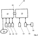
- Fig. 2 shows a system 44 having two multiport devices 10 which are connected by a data connection in the form of a fast communication backplane 46.
- One of the multiport devices 10 is connected to the Internet 34 and is also connected to a number of field devices.
- One field device is formed by a PLC 48.
- the PLC 48 controls a servo drive 50 that is also connected to the multiport device 10.
- the PLC 48 may control the servo drive 50 using the protocol EIP (Ethernet/IP).
- a further PLC 52 may also be connected to one of the multiport devices 10.
- the further PLC 52 controls a magnetic actor 54 that is connected to the other multiport device 10.
- the magnetic actor 54 is controlled via the field bus protocol Sercos III. A translation of the different protocols is performed by the multiport devices 10.
- One of the multiport device 10 is connected to an external gateway 56 which in turn is connected to an I/O-(input/output-)device 58.
- the PLC 48 is able to communicate with the I/O device 58 via the external gateway 56 and via the two multiport devices 10, wherein within the multiport devices 10 data from the I/O device 58 is transmitted from the matrix switcher 18 to the fast communication backplane 48 and onto the next matrix switcher 18 and finally arrives at the PLC 48.
Landscapes
- Physics & Mathematics (AREA)
- Engineering & Computer Science (AREA)
- General Physics & Mathematics (AREA)
- Automation & Control Theory (AREA)
- Mathematical Physics (AREA)
- Computer Networks & Wireless Communication (AREA)
- Signal Processing (AREA)
- Data Exchanges In Wide-Area Networks (AREA)
Abstract
- a plurality of communication ports for the connection of field devices and for data communication between the multiport device and the field devices,
- a matrix switcher configured to enable data communication between said communication ports and/or between said field devices,
- a control unit configured to generate a plurality of communication rules and to control said matrix switcher based on at least said plurality of communication rules in order to affect data communication between said communication ports and/or between said field devices, wherein the control unit is configured to group one or more of the communication rules into one or more function modules and wherein one or more function modules are assigned to at least one of the communication ports.
Description
- The present invention relates to a multiport device adapted to be connected to a plurality of field devices, particularly using industrial Ethernet connections.
- Field devices are used in a variety of industrial processes. These industrial processes become more and more automated which leads to an increasingly complex and demanding automation environment.
- The increasing demands on automation lead to increasing demands on the field devices. Particularly, the field devices have to be energy efficient and low cost devices which at the same time are cyber secure, have Internet access for remote diagnosis and monitoring and comprise a high performance. Furthermore, it is required that field devices become more and more compact and easier to use.
- These requirements on automation processes lead to expensive development and validation cycles. Also a complex programming of industrial machines and their field devices may be required. The high requirements in turn require highly qualified personnel and at the same time may raise compatibility issues between devices of different manufacturers.
- It is the object of the present invention to provide means that allow highly complex and demanding automation of industrial processes with reduced cost and effort.
- This object is solved by a multiport device having the features of claim 1.
- Particularly, this object is satisfied by a multiport device adapted to be connected to a plurality of field devices, particularly using industrial Ethernet connections, wherein the multiport device comprises:
- a plurality of communication ports for the connection of field devices and for data communication between the multiport device and the field devices,
- a matrix switcher configured to enable data communication between said communication ports and/or between said field devices,
- a control unit configured to generate a plurality of communication rules and to control said matrix switcher based on at least said plurality of communication rules in order to affect data communication between said communication ports and/or between said field devices, wherein the control unit is configured to group one or more of the communication rules into one or more function modules and wherein one or more function modules are, preferably individually, assigned to at least one of the communication ports.
- In other words, the multiport device of the invention is adapted to assign function modules to specific communication ports wherein these function modules then add additional functionality to the specific communication port and thereby add additional functionality to the field device connected to the specific communication port. Particularly, each communication port (and thus each connected field device) can be configured and/or controlled independently. This leads to an increased functionality of the field device, wherein the additional functionality is provided by the multiport device. Therefore, the field device itself does not have to provide for the additional functionality and can hence comprise cheaper components and can be developed with less effort.
- In the following further details of the multiport device of the invention are described.
- The communication rules may be based on/adapted to the field devices connected to the multiport device. This means that for different connected field devices different communication rules may be generated. The communication rules are at least in part generated by the multiport device itself, e.g. by the control unit.
- For example, the communication rules may allow communication of the multiport device with different field devices using different protocols (e.g. different field bus protocols) and allow assigning functions (i.e. function modules) to a specific communication port, as laid out above. Furthermore, it is possible to assign a function module for traffic optimization to one of the communication ports. Thereby, the communication rules of this function module may provide for an optimized data flow for the specific communication port. For the sake of clarity, it is pointed out that several function modules can be assigned to one single communication port, simultaneously.
- In general, function modules can be adapted to provide any conceivable additional functionality. Particularly, the function modules may allow to configure, to control, to monitor and/or to secure the field devices connected to the multiport device.
- Apart from the mentioned field devices, also further devices such as gateways, engineering tools (e.g. on a standard PC), the Internet and/or Cloud servers may be connected to the multiport device, preferably using the communication ports. For example, the engineering tools may be used to program and/or configure field devices that are connected to the multiport device.
- As used herein, "communication" means a digital transfer of data, e.g. using data packets (i.e. data telegrams), particularly within an industrial Ethernet connection.
- A function module can comprise several communication rules, wherein the communication rules affect and/or alter data communication of the multiport device.
- Thereby, data communication between the communication ports and/or between the field devices may be affected and/or altered. For example, a function module may comprise communication rules which alter data communication such that communication with a field device using e.g. a field bus protocol is possible.
- The function modules may only affect and/or alter the communication performed by the communication port they are assigned to. The multiport device can handle different communication ports and/or field devices separately from each other.
- The communication rules may be provided by a rule handler which can be part of the control unit.
- The matrix switcher may be configured to selectively allow data communication between different communication ports. Particularly, the matrix switcher can be programmed to establish data connections between specific communication ports. The function modules and/or the communication rules may determine which communication ports are allowed to communicate with each other. The matrix switcher preferably comprises a separate data connection with each of the communication ports. The matrix switcher may selectively interconnect the communication ports and/or be adapted to selectively route data communication from one communication port to one or more other communication ports.
- The field devices that may be connected to the multiport device may comprise sensors, actors, control devices (e.g. programmable logic controllers - PLCs) and the like.
- Due to the possibility of adding functionality to the field devices, wherein the added functionality is hosted on the multiport device, lower costs for the field devices are achievable. Furthermore, function modules can be provided that allow a backwards compatibility of the field devices or a faster communication with the field devices. Thereby, higher automation requirements can be fulfilled and/or the life cycle even of outdated devices can be prolonged.
- Preferably, the communication rules and/or the function modules are stored within a database of the control unit. The communication rules and/or the function modules can be enforced by a rule handler within the control unit.
- Advantageously, the control unit is adapted to update the function modules and/or the communication rules during operation of the multiport device. Thereby, hot-plugging of field devices on the communication ports is possible. For example, if a field device is connected to a communication port, a configuration at run-time is provided for the new field device and/or the respective communication port.
- It is preferred that at least one of the function modules is adapted to optimize data communication between the communication ports and/or between the field devices. Traffic optimization can be performed for at least one communication port. Alternatively, traffic optimization can be collectively performed for more than one of the communication ports, wherein e.g. traffic between the more than one communication ports is optimized.
- The traffic optimization can be based on pattern recognition, wherein particularly the used communication port, the sent time of data, the length and/or volume of the transmitted data and/or the kind of transmitted data is considered.
- Preferably, the control unit is adapted to use machine learning techniques to optimize data communication, particularly using a feed-forward multi-layer neural network. In other words, traffic optimization is based on machine learning and/or neural networks. Particularly, an unsupervised learning process can be utilized.
- For the learning process, the neural network can be supplied with information about data communication through the multiport device. Particularly, an incoming and/or a destination communication port, a telegram type, a time stamp and/or a data length of the data communication can be inputted into the neural network. The neural network can then output information about the expected usage of specific communication ports, an expected cycle time of data communications, an expected jitter of data communications and/or an expected priority of data communications. From the output of the neural network, a re-routing of communication paths, e.g. in case of communication loss, suboptimal timing, etc., can be performed.
- Advantageously, the parallel processing in such neural networks is fast and also allows a fast learning which in turn leads to a fast response to new conditions, e.g. if new devices are connected to the multiport device of the invention.
- Alternatively or additionally, a support vector machine (SVM) can be used as a machine learning technique. In contrast to the above-mentioned machine learning technique, a SVM uses a supervised learning process.
- Further preferably, the function module adapted to optimize data communication is configured to reserve time slots at a respective communication port for expected and/or cyclic data telegrams. For example, the control unit can learn (e.g. using the neural network) when a cyclic telegram is expected. The matrix switcher can then be operated such by the control unit (and/or by a function module) that the destination port of the cyclic telegram is held clear of data traffic for the expected time-period. In this connection, it is possible that the neural network updates the communication rules of a function module to reflect the information learned by the neural network. For learning pattern of data communication within the matrix switcher and/or within the multiport device, the neural network may survey the data communication of at least some of the communication ports.
- It is preferred that the function module adapted to optimize data communication is configured to prioritize incoming data communication, preferably according to the communication protocol used, and to transmit the respective data communication in accordance with its priority using the matrix switcher. Particularly, cut-through telegrams may have the highest priority and may be transmitted from a receiving communication port to a destination communication port immediately using the matrix switcher. The second highest priority may be given to industrial Ethernet connections (i.e. real-time Ethernet and/or field bus connections). The third highest priority may be assigned to standard Ethernet data communication. Data communication of standard Ethernet therefore has to wait until all waiting data communication of industrial Ethernet connections has been transmitted by the matrix switcher. Correspondingly, industrial Ethernet connections have to wait until all cut-through telegrams have been transmitted by the matrix switcher.
- Particularly, the control unit may use a sorting algorithm which first detects if a telegram is a cut-through telegram. If that is the case, the telegram is immediately forwarded to the destination communication port. If a telegram is not a cut-through telegram, it is next determined if the telegram is a part of an industrial and/or real-time Ethernet communication. If that is the case, the telegram is queued in a queue for the second highest priority. Instead, if the telegram is not part of an industrial and/or real-time Ethernet connection, it is queued in a lower level queue (third highest priority queue).
- Preferably, all telegrams or at least the cut-through telegrams are sent to a data optimizer within the control unit. The data optimizer may comprise the above-mentioned neural network and allows optimizing data communication within the matrix switcher.
- A cut-through telegram is a telegram that is forwarded to the configured port without any prior analysis. An example for cut-through telegrams are Sercos telegrams. After the telegram is sent/forwarded, a copy of it is forwarded to the data optimizer for analysis and creation of rules for the specific ports (for example: time slot reservation).
- It is further preferred if the matrix switcher and/or the control unit are adapted to forward data telegrams in OSI layer 1 or 2 immediately and/or to save data telegrams in OSI layer 3 in prioritized queues. Data telegrams in OSI layer 1 or 2 can be cut-through telegrams and are thus forwarded immediately. Data telegrams in OSI layer 3 may be telegrams of industrial Ethernet or standard Ethernet connections. It has to be understood that for all telegrams further services may be executed, if they are configured for the respective communication port (i.e. if the corresponding function module exists and is assigned to the corresponding communication port).
- Advantageously, at least one of the function modules is adapted to provide additional functionality selectively to at least one of the field devices, preferably when a field device is connected to the multiport device, wherein the additional functionality is provided by the multiport device.
- In other words, the additional functionality is coupled/linked to a specific communication port and thereby may be coupled/linked to a specific field device. When viewed from an external point of view, the additional functionality then seems to be provided by the field device but is actually provided by the multiport device. As laid out above, the field device can thus be cheaper, less complex and can be developed faster as the additional functionality is not needed to be provided by the field device itself.
- For example, the additional functionality comprises at least one of the following:
- cyber security functionality, preferably a firewall and/or a login server;
- webserver functionality;
- VPN (Virtual Private Network) functionality; and
- intruder detection.
- For example, a servo drive may be connected to a communication port of the multiport device, wherein a function module that provides firewall functionality to the communication port to which the servo drive is connected can be activated. If a data connection to the servo drive is established from outside the multiport device (using a further communication port of the multiport device), this data connection reaches through the multiport device up to the servo drive. Due to the activated function module the data connection to the servo drive is led through a firewall, i.e. strict rules which data packets or data telegrams may be forwarded to the servo drive are applied.
- As another example, webserver functionality may be activated for the servo drive. If the servo drive is then contacted via a data connection, a website may be displayed, wherein the website may appear to be provided by the servo drive (however in reality it is provided by the multiport device). A user can then use the website to configure the servo drive.
- Function modules can be assigned individually and separately to the communication ports. It is therefore possible that different firewalls and/or different webservers can be activated for different communication ports.
- As the above-mentioned additional functionality is provided by the multiport device, the servo drive is not required to have a powerful processor in order to perform the functionality of a firewall and/or a webserver itself.
- In order to gather information about the field devices connected to the multiport device, the control unit can be configured to (periodically) scan the field devices connected to the communication ports of the multiport device and/or to read configuration tables (i.e. configuration files) of the field devices. During the scan of the field devices, the multiport device may read information about the MAC-address, the supported functionality, the name and/or the hardware and/or software identification from each field device. From the information gathered about the field devices, e.g. the webserver functionality may be adapted to the specific connected field device, particularly based on the configuration table.
- It is preferred if at least one of the function modules is adapted to provide a redundant data communication by assigning two or more communication ports to the same field device and/or by sending the same information to two or more communication ports. All of the two or more communication ports may be physically connected with the same field device. Thereby, an increased availability of the field device is assured. For example, communication data can be transmitted to the field device using either one of the communication ports. It is also possible to create a fault tolerance function module that provides rules for dealing with the failure or disconnection of a field device. Particularly, the communication rules can be such that the remaining functionality of the field devices connected to the multiport device remains intact and/or untouched. For this purpose, the communication rules can initiate a preprogrammed re-routing of data communication. For example, more than one field device can be used by the communication rules to ensure fault tolerance. If one field device fails and/or is disconnected from the multiport device, the other field device(s) take over the functionality of the failing field device.
- Preferably, the matrix switcher and/or the control unit are adapted to translate different communication protocols such that data communication between field devices using different communication protocols is enabled. Thus, the multiport device may provide gateway functionality. The gateway functionality may be comprised in one function module that is activated by the control unit and is assigned to one or more communication ports. Particularly, this function module may translate one Ethernet-based protocol into another. Thereby, field devices connected to the multiport device may use different Ethernet and/or field bus protocols and can nonetheless communicate seamlessly.
- Further preferably, the matrix switcher and/or the communication port are adapted to support real-time Ethernet connections and standard Ethernet connections, wherein at least the real-time Ethernet connections are based on different communication protocols. Also, the standard Ethernet connections may be based on different communication protocols. Real-time Ethernet is equivalent to industrial Ethernet. The different protocols based on real-time Ethernet connections may comprise field bus protocols, particularly the field bus protocols Sercos III, Ether-CAT, Profinet and the like. In order to support the real-time Ethernet connections, the control unit may comprise a real-time clock (RTC). Apart from the Ethernet-based protocols, the multiport device may also support non-Ethernet-based protocols such as Sercos I and II and/or Profibus. For this purpose, the multiport device may comprise non-Ethernet communication ports and/or communication ports that support both Ethernet-based and non-Ethernet-based data communication. The multiport device can also be adapted to translate Ethernet-based data communication into non-Ethernet-based data communication and vice versa.
- Advantageously, the matrix switcher and/or the communication ports are adapted to scan the communication ports for connected field devices and to generate the communication rules based on the detected field devices. During the scan of the field devices, configuration files of the field devices can be transferred to the multiport device (i.e. downloaded from the field devices). Communication rules can then be generated based on the information contained in the configuration files. In addition to this automatic configuration of the multiport device, the multiport device can also be configured manually, i.e. communication rules and/or function modules can be provided manually. For this purpose, the multiport device can be accessed via a webserver within the multiport device, which displays a website that allows the configuration of the multiport device using a graphical user interface (GUI).
- The scan of field devices connected to the multiport device can be performed periodically, in order to detect hot-plugged new field devices and/or removed field devices.
- The matrix switcher can - apart from the communication ports - also comprise input and/or output ports. These input and/or output ports can be adapted for analogue and/or digital data. For example, a temperature sensor can be connected to an input port. A status light which indicates the operating condition of the multiport device may be connected to one of the output ports.
- The input and/or output ports can be used to provide functionality for all (or a limited selection) of field devices connected to the multiport device. For example, one of the input ports can be connected to an emergency stop. When the emergency stop is activated, the multiport device can then stop all (or a limited selection) of the field devices connected to the multiport device. Correspondingly, an output port may be used to distribute an "enable operation" signal to all (or a limited selection) of the field devices connected to the multiport device.
- The multiport device can comprise a human machine interface (HMI). The HMI can be formed by a display that is attached to a housing of the multiport device. The HMI may be adapted to allow configuring the multiport device and/or to display status information about the multiport device.
- It is preferred if the multiport device comprises a multi-core system-on-chip (SOC) having at least one CPU (Central Processing Unit) and at least one FPGA (Field Programmable Gate Array), wherein the CPU is adapted to provide the functionality of the control unit and/or the FPGA is adapted to provide the functionality of the matrix switcher. Preferably, the CPU may have one computational core for each communication port or for a group of several communication ports. Thereby, a high speed of processing data in connection with each communication port can be provided.
- The CPU may be running a firmware for executing the different function modules assigned to the communication ports. The firmware may also execute an operating system of the multiport device and/or the functionality of the control unit.
- The use of an FPGA for the matrix switcher is especially advantageous as the communication rules assigned to each communication port can be mapped in the programing of the FPGA. The FPGA also allows to independently control the different communication ports.
- The invention further relates to a method of operating a multiport device. The method comprises:
- connecting a plurality of field devices to communication ports of the multiport device,
- generating a plurality of communication rules wherein one or more of the communication rules are grouped into one or more function modules and wherein one or more function modules are assigned to at least one of the communication ports,
- controlling a matrix switcher based on at least said plurality of communication rules and/or said function modules in order to affect data communication between said field devices.
- The invention also relates to a system comprising at least two multiport devices as described above. The two multiport devices may be connected to each other using a data connection. Preferably, the connection of the two multiport devices is based on a master-slave-principle (i.e. a producer-consumer-principle) and uses a fast communication backplane. It is also possible to connect more than two multiport devices wherein one of the multiport devices is configured as a master and the remaining multiport devices are configured as a slave. The master multiport device may supervise the operation of the slave multiport devices. Particularly, the master multiport device may not only process the local (i.e. its) communication ports but also the communication ports of the further multiport devices. The communication ports of the further multiport devices may then be regarded as virtual ports by the master multiport device.
- When two or more multiport devices are connected, the multiport devices may merge their activated function modules and their information about connected field devices. The merged information is preferably transferred to the master multiport device.
- Furthermore, the invention also relates to a system comprising at least one multiport device (as described above) and at least one field device connected to one of the communication ports of the multiport device using an industrial Ethernet connection.
- Finally, the invention also relates to an industrial machine, comprising multiple field devices (e.g. sensors and/or actors and/or control devices, e.g. PLCs), wherein the field devices are connected to a multiport device using industrial Ethernet connections. The multiport device may be part of the industrial machine.
- The advantages, preferable features and/or embodiments of the inventive multiport device described in the foregoing also apply to the inventive method, to the inventive systems and to the inventive industrial machine.
- The invention will be explained in the following in detail by means of exemplary embodiments and with reference to the Figures:
- Fig. 1
- shows a multiport device connected to several field devices; and
- Fig. 2
- shows a system of two multiport devices.
-
Fig. 1 shows amultiport device 10. Themultiport device 10 comprises severalEthernet communication ports 12. Furthermore, themultiport device 10 comprisesinputs 14 and outputs 16. - The
Ethernet communication ports 12, theinputs 14 and theoutputs 16 are each separately connected to amatrix switcher 18, which is part of themultiport device 10. Thematrix switcher 18 allows data connections between theEthernet communication ports 12, theinputs 14 and theoutputs 16. - The
matrix switcher 18 is connected to acontrol unit 20. Thecontrol unit 20 controls operation of thematrix switcher 18. Furthermore, thecontrol unit 20 is part of themultiport device 10 and has a data connection to thematrix switcher 18. - The
control unit 20 and thematrix switcher 18 are formed by a single system on chip 22 (SOC). Thematrix switcher 18 is formed by an FPGA and thecontrol unit 20 is formed by a CPU of theSOC 22. - The
control unit 20 comprises a managingunit 24 which collects information, detects trends and optimizes dataflow through thematrix switcher 18. - The
control unit 20 furthermore comprises arule handler 26 and a multitude of function modules 28 (28a, 28b, 28c). Thecontrol unit 20 furthermore comprises adatabase 30. - One of the
Ethernet communication ports 12 of themultiport device 10 is connected via astandard Ethernet connection 32 to theInternet 34. The otherEthernet communication ports 12 are connected to several field devices 38 (three are depicted inFig. 1 ) viaindustrial Ethernet connections 36. - One
input 14 is connected to atemperature sensor 40, whereas oneoutput 12 is connected to astatus light 42. - During operation of the
multiport device 10 different function modules 28 can be assigned (indicated by arrows) to the differentEthernet communication ports 12. - In the example of
Fig. 1 , afunction module 28a for webserver functionality may be assigned to theEthernet communication port 12 that is connected to theInternet 34. Thus, if a user tries to connect to themultiport device 10 via theInternet 34, a website can be displayed e.g. on a browser of the user that allows the user to configure themultiport device 10 using the website. - The
function module 28a having the webserver functionality may also be assigned to one of theEthernet communication ports 12 to which one of thefield devices 38 is connected. If a user then tries to connect with therespective field device 38, a different website will be displayed which will give the impression as if thefield device 38 hosts the website. The website can then allow a user to configure therespective field device 38. - Furthermore, a
function module 28b which provides firewall and/or VPN capability can be assigned to the Ethernet communication ports to which thefield devices 38 are connected. In that case only data connections which are part of a virtual private network (VPN) and which additionally pass through the firewall are routed through to therespective field device 38. - Also, traffic optimization can be activated by activating a
corresponding function module 28c and assigning it to theEthernet communication ports 12. Thereby, for example, standard Ethernet traffic from theInternet 34 is delayed, if communications using industrial Ethernet communications 36 (i.e. real-time communications) are in progress. - Due to the assignment of the function modules 28 to the
Ethernet communication ports 12 additional functionality seemingly is provided by thefield devices 38. However, in reality, this functionality is actually provided by themultiport device 10. Thereby, thefield devices 38 can comprise cheaper parts and are not required to provide a high level of functionality. -
Fig. 2 shows asystem 44 having twomultiport devices 10 which are connected by a data connection in the form of afast communication backplane 46. - One of the
multiport devices 10 is connected to theInternet 34 and is also connected to a number of field devices. One field device is formed by aPLC 48. ThePLC 48 controls aservo drive 50 that is also connected to themultiport device 10. ThePLC 48 may control theservo drive 50 using the protocol EIP (Ethernet/IP). Afurther PLC 52 may also be connected to one of themultiport devices 10. Thefurther PLC 52 controls amagnetic actor 54 that is connected to theother multiport device 10. Themagnetic actor 54 is controlled via the field bus protocol Sercos III. A translation of the different protocols is performed by themultiport devices 10. - One of the
multiport device 10 is connected to anexternal gateway 56 which in turn is connected to an I/O-(input/output-)device 58. ThePLC 48 is able to communicate with the I/O device 58 via theexternal gateway 56 and via the twomultiport devices 10, wherein within themultiport devices 10 data from the I/O device 58 is transmitted from thematrix switcher 18 to thefast communication backplane 48 and onto thenext matrix switcher 18 and finally arrives at thePLC 48. - Due to the combination of several
multiport devices 10 an easily scalable and flexible (i.e. field bus protocol independent) communication is possible betweendifferent field devices -
- 10
- multiport device
- 12
- Ethernet communication port
- 14
- input
- 16
- output
- 18
- matrix switcher
- 20
- control unit
- 22
- SOC
- 24
- managing unit
- 26
- rule handler
- 28
- function module
- 28a
- webserver function module
- 28b
- firewall and/or VPN function module
- 28c
- traffic optimization function module
- 30
- database
- 32
- standard Ethernet connection
- 34
- Internet
- 36
- industrial Ethernet connection
- 38
- field device
- 40
- temperature sensor
- 42
- status light
- 44
- system
- 46
- fast communication backplane
- 48
- PLC
- 50
- servo drive
- 52
- further PLC
- 54
- magnetic actor
- 56
- external gateway
- 58
- I/O-device
Claims (15)
- A multiport device (10) adapted to be connected to a plurality of field devices (38, 48, 50, 52, 54, 56, 58), particularly using industrial Ethernet connections (36), wherein the multiport device (10) comprises:- a plurality of communication ports (12) for the connection of field devices (38, 48, 50, 52, 54, 56, 58) and for data communication between the multiport device (10) and the field devices (38, 48, 50, 52, 54, 56, 58),- a matrix switcher (18) configured to enable data communication between said communication ports (12) and/or between said field devices (38, 48, 50, 52, 54, 56, 58),- a control unit (20) configured to generate a plurality of communication rules and to control said matrix switcher (18) based on at least said plurality of communication rules in order to affect data communication between said communication ports (12) and/or between said field devices (38, 48, 50, 52, 54, 56, 58),wherein the control unit (20) is configured to group one or more of the communication rules into one or more function modules (28) and wherein one or more function modules (28) are assigned to at least one of the communication ports (12).
- The multiport device (10) of claim 1, wherein
the control unit (20) is adapted to update the function modules (28) and/or the communication rules during operation of the multiport device (10). - The multiport device (10) of claim 1 or 2, wherein
at least one of the function modules (28) is adapted to optimize data communication between the communication ports (12) and/or between the field devices (38, 48, 50, 52, 54, 56, 58). - The multiport device (10) of claim 3, wherein
the control unit (20) is adapted to use machine learning techniques to optimize data communication, particularly using a feed-forward multi-layer neural network. - The multiport device (10) of claims 3 and 4, wherein
the function module (28) adapted to optimize data communication is configured to reserve timeslots at a respective communication port (12) for expected and/or cyclic data telegrams. - The multiport device (10) of claims 3 to 5, wherein
the function module (28) adapted to optimize data communication is configured to prioritize incoming data communication, preferably according to the communication protocol used, and to transmit the respective data communication in accordance with its priority using the matrix switcher (18). - The multiport device (10) of claim 6, wherein
the matrix switcher (18) and/or the control unit (20) are adapted to forward data telegrams in OSI layer 1 or 2 immediately and/or to save data telegrams in OSI layer 3 in prioritized queues. - The multiport device (10) of at least one of the preceding claims, wherein at least one of the function modules (28) is adapted to provide additional functionality selectively to at least one of the field devices (38, 48, 50, 52, 54, 56, 58), preferably when the field device (38, 48, 50, 52, 54, 56, 58) is connected to the multiport device (10), wherein the additional functionality is provided by the multiport device (10).
- The multiport device (10) of claim 8, wherein
the additional functionality comprises at least one of the following:- cybersecurity functionality, preferably a firewall and/or a login server,- webserver functionality,- VPN functionality and- intruder detection. - The multiport device (10) of at least one of the preceding claims, wherein at least one of the function modules (28) is adapted to provide a redundant data communication by assigning two or more communication ports (12) to the same field device (38, 48, 50, 52, 54, 56, 58) and/or by sending the same information to two or more communication ports (12).
- The multiport device (10) of at least one of the preceding claims, wherein the matrix switcher (18) and/or the control unit (20) are adapted to translate different communication protocols such that data communication between field devices (38, 48, 50, 52, 54, 56, 58) using different communication protocols is enabled.
- The multiport device (10) of at least one of the preceding claims, wherein the matrix switcher (18) and/or the communication port are adapted to support real-time Ethernet connections and standard Ethernet connections, wherein at least the real-time Ethernet connections are based on different communication protocols.
- The multiport device (10) of at least one of the preceding claims, wherein the matrix switcher (18) and/or the communication ports (12) are adapted to scan the communication ports (12) for connected field devices (38, 48, 50, 52, 54, 56, 58) and to generate the communication rules based on the detected field devices (38, 48, 50, 52, 54, 56, 58).
- The multiport device (10) of at least one of the preceding claims, comprising a multi-core System-On-Chip (22) having at least one CPU and at least one FPGA, wherein the CPU is adapted to provide the functionality of the control unit (20) and the FPGA is adapted to provide the functionality of the matrix switcher (18).
- A method of operating a multiport device (10), comprising:- connecting a plurality of field devices (38, 48, 50, 52, 54, 56, 58) to communication ports (12) of the multiport device (10),- generating a plurality of communication rules wherein one or more of the communication rules are grouped into one or more function modules (28) and wherein one or more function modules (28) are assigned to at least one of the communication ports (12),- controlling a matrix switcher (18) based on at least said plurality of communication rules and/or said function modules (28) in order to affect data communication between said field devices (38, 48, 50, 52, 54, 56, 58).
Priority Applications (1)
| Application Number | Priority Date | Filing Date | Title |
|---|---|---|---|
| EP17306025.2A EP3439254B1 (en) | 2017-08-01 | 2017-08-01 | A multiport device |
Applications Claiming Priority (1)
| Application Number | Priority Date | Filing Date | Title |
|---|---|---|---|
| EP17306025.2A EP3439254B1 (en) | 2017-08-01 | 2017-08-01 | A multiport device |
Publications (2)
| Publication Number | Publication Date |
|---|---|
| EP3439254A1 true EP3439254A1 (en) | 2019-02-06 |
| EP3439254B1 EP3439254B1 (en) | 2021-10-06 |
Family
ID=60162152
Family Applications (1)
| Application Number | Title | Priority Date | Filing Date |
|---|---|---|---|
| EP17306025.2A Active EP3439254B1 (en) | 2017-08-01 | 2017-08-01 | A multiport device |
Country Status (1)
| Country | Link |
|---|---|
| EP (1) | EP3439254B1 (en) |
Cited By (1)
| Publication number | Priority date | Publication date | Assignee | Title |
|---|---|---|---|---|
| EP4105744A4 (en) * | 2020-11-30 | 2024-03-20 | Ilpum Corp. | Plc for providing space-efficient input/output interface |
Citations (5)
| Publication number | Priority date | Publication date | Assignee | Title |
|---|---|---|---|---|
| US20060109866A1 (en) * | 2002-10-25 | 2006-05-25 | Elektro Beckhoff Gmbh | Methods, interface unit and nodes for using in parallel a communication network for real-time applications and for non-real-time applications |
| US20070280285A1 (en) * | 2006-06-06 | 2007-12-06 | Daniel Measurement & Control, Inc. | Method and system of field device protocol masking |
| US20150154136A1 (en) * | 2011-12-30 | 2015-06-04 | Bedrock Automation Platforms Inc. | Input/output module with multi-channel switching capability |
| US20160292004A1 (en) * | 2015-03-31 | 2016-10-06 | Omron Corporation | Controller |
| WO2016172514A1 (en) * | 2015-04-24 | 2016-10-27 | Siemens Aktiengesellschaft | Improving control system resilience by highly coupling security functions with control |
-
2017
- 2017-08-01 EP EP17306025.2A patent/EP3439254B1/en active Active
Patent Citations (5)
| Publication number | Priority date | Publication date | Assignee | Title |
|---|---|---|---|---|
| US20060109866A1 (en) * | 2002-10-25 | 2006-05-25 | Elektro Beckhoff Gmbh | Methods, interface unit and nodes for using in parallel a communication network for real-time applications and for non-real-time applications |
| US20070280285A1 (en) * | 2006-06-06 | 2007-12-06 | Daniel Measurement & Control, Inc. | Method and system of field device protocol masking |
| US20150154136A1 (en) * | 2011-12-30 | 2015-06-04 | Bedrock Automation Platforms Inc. | Input/output module with multi-channel switching capability |
| US20160292004A1 (en) * | 2015-03-31 | 2016-10-06 | Omron Corporation | Controller |
| WO2016172514A1 (en) * | 2015-04-24 | 2016-10-27 | Siemens Aktiengesellschaft | Improving control system resilience by highly coupling security functions with control |
Non-Patent Citations (2)
| Title |
|---|
| HODO ELIKE ET AL: "Threat analysis of IoT networks using artificial neural network intrusion detection system", 2016 INTERNATIONAL SYMPOSIUM ON NETWORKS, COMPUTERS AND COMMUNICATIONS (ISNCC), IEEE, 11 May 2016 (2016-05-11), pages 1 - 6, XP033005222, DOI: 10.1109/ISNCC.2016.7746067 * |
| SIEMENS: "PROFINET System Description", 31 March 2012 (2012-03-31), XP055442928, Retrieved from the Internet <URL:http://www.siemens.fi/pool/products/industry/iadt_is/tuotteet/automaatiotekniikka/teollinen_tiedonsiirto/profinet/man_pnsystem_description.pdf> [retrieved on 20180122] * |
Cited By (2)
| Publication number | Priority date | Publication date | Assignee | Title |
|---|---|---|---|---|
| EP4105744A4 (en) * | 2020-11-30 | 2024-03-20 | Ilpum Corp. | Plc for providing space-efficient input/output interface |
| US12140922B2 (en) | 2020-11-30 | 2024-11-12 | Ilpum Corp. | PLC for providing space-efficient input/output interface |
Also Published As
| Publication number | Publication date |
|---|---|
| EP3439254B1 (en) | 2021-10-06 |
Similar Documents
| Publication | Publication Date | Title |
|---|---|---|
| JP6638089B2 (en) | Connection unit, monitoring system and operation method for operation of automation system | |
| US5978578A (en) | Openbus system for control automation networks | |
| Lin et al. | An inside look at industrial Ethernet communication protocols | |
| EP2244190B1 (en) | Constituting a control system with virtual and physical backplanes and modules as building blocks | |
| US8509927B2 (en) | Control system for controlling safety-critical processes | |
| CN101784967B (en) | Control node and control | |
| CN110320793B (en) | Method and fail-safe control unit for constructing redundant communication links | |
| US10805116B2 (en) | Gateway and method for connecting a data source system to an IT system | |
| US9928206B2 (en) | Dedicated LAN interface per IPMI instance on a multiple baseboard management controller (BMC) system with single physical network interface | |
| US10038670B2 (en) | System and method for controlling access to a plant network | |
| JP6657456B2 (en) | Gateway system for heterogeneous fieldbus | |
| US20090204695A1 (en) | Automation network comprising network components that produce status messages | |
| US7913016B2 (en) | Method of determining request transmission priority subject to request source and transmitting request subject to such request transmission priority in application of fieldbus communication framework | |
| Kaestner et al. | Design of an efficient communication architecture for cyber-physical production systems | |
| EP3439254B1 (en) | A multiport device | |
| US20220137604A1 (en) | Coordination Device and Method for Providing Control Applications via a Communication Network for Transmitting Time-Critical Data | |
| KR101038619B1 (en) | Network-Based Control Modules for Multi-DOF Smart Actuators for Robots | |
| CN102483624A (en) | Providing operating data relating to a device using a diagnostic data server as a further field bus master | |
| Garcia et al. | An approach of load balancers for low-cost cppss in software-defined networking architecture | |
| EP2482153B1 (en) | Method and computer program for configuring an automation system | |
| JP7577894B2 (en) | Method and system for providing time-critical services using a flow-controlled environment - Patents.com | |
| Sridevi et al. | Effective protocols for industrial communication | |
| CN110663226A (en) | Status signal output | |
| Ha et al. | A new approach to secure industrial automation systems based on revolution pi modules | |
| CN116491108A (en) | Edge device and method for providing redundant functionality on the edge device |
Legal Events
| Date | Code | Title | Description |
|---|---|---|---|
| PUAI | Public reference made under article 153(3) epc to a published international application that has entered the european phase |
Free format text: ORIGINAL CODE: 0009012 |
|
| STAA | Information on the status of an ep patent application or granted ep patent |
Free format text: STATUS: THE APPLICATION HAS BEEN PUBLISHED |
|
| AK | Designated contracting states |
Kind code of ref document: A1 Designated state(s): AL AT BE BG CH CY CZ DE DK EE ES FI FR GB GR HR HU IE IS IT LI LT LU LV MC MK MT NL NO PL PT RO RS SE SI SK SM TR |
|
| AX | Request for extension of the european patent |
Extension state: BA ME |
|
| STAA | Information on the status of an ep patent application or granted ep patent |
Free format text: STATUS: REQUEST FOR EXAMINATION WAS MADE |
|
| 17P | Request for examination filed |
Effective date: 20190625 |
|
| RBV | Designated contracting states (corrected) |
Designated state(s): AL AT BE BG CH CY CZ DE DK EE ES FI FR GB GR HR HU IE IS IT LI LT LU LV MC MK MT NL NO PL PT RO RS SE SI SK SM TR |
|
| STAA | Information on the status of an ep patent application or granted ep patent |
Free format text: STATUS: EXAMINATION IS IN PROGRESS |
|
| 17Q | First examination report despatched |
Effective date: 20191104 |
|
| GRAP | Despatch of communication of intention to grant a patent |
Free format text: ORIGINAL CODE: EPIDOSNIGR1 |
|
| STAA | Information on the status of an ep patent application or granted ep patent |
Free format text: STATUS: GRANT OF PATENT IS INTENDED |
|
| RIC1 | Information provided on ipc code assigned before grant |
Ipc: H04L 12/933 20130101AFI20210401BHEP Ipc: G05B 19/042 20060101ALI20210401BHEP |
|
| INTG | Intention to grant announced |
Effective date: 20210419 |
|
| GRAS | Grant fee paid |
Free format text: ORIGINAL CODE: EPIDOSNIGR3 |
|
| GRAA | (expected) grant |
Free format text: ORIGINAL CODE: 0009210 |
|
| STAA | Information on the status of an ep patent application or granted ep patent |
Free format text: STATUS: THE PATENT HAS BEEN GRANTED |
|
| AK | Designated contracting states |
Kind code of ref document: B1 Designated state(s): AL AT BE BG CH CY CZ DE DK EE ES FI FR GB GR HR HU IE IS IT LI LT LU LV MC MK MT NL NO PL PT RO RS SE SI SK SM TR |
|
| REG | Reference to a national code |
Ref country code: GB Ref legal event code: FG4D |
|
| REG | Reference to a national code |
Ref country code: CH Ref legal event code: EP Ref country code: AT Ref legal event code: REF Ref document number: 1437196 Country of ref document: AT Kind code of ref document: T Effective date: 20211015 |
|
| REG | Reference to a national code |
Ref country code: IE Ref legal event code: FG4D |
|
| REG | Reference to a national code |
Ref country code: DE Ref legal event code: R096 Ref document number: 602017047085 Country of ref document: DE |
|
| REG | Reference to a national code |
Ref country code: DE Ref legal event code: R079 Ref document number: 602017047085 Country of ref document: DE Free format text: PREVIOUS MAIN CLASS: H04L0012933000 Ipc: H04L0049100000 |
|
| REG | Reference to a national code |
Ref country code: LT Ref legal event code: MG9D |
|
| REG | Reference to a national code |
Ref country code: NL Ref legal event code: MP Effective date: 20211006 |
|
| REG | Reference to a national code |
Ref country code: AT Ref legal event code: MK05 Ref document number: 1437196 Country of ref document: AT Kind code of ref document: T Effective date: 20211006 |
|
| PG25 | Lapsed in a contracting state [announced via postgrant information from national office to epo] |
Ref country code: RS Free format text: LAPSE BECAUSE OF FAILURE TO SUBMIT A TRANSLATION OF THE DESCRIPTION OR TO PAY THE FEE WITHIN THE PRESCRIBED TIME-LIMIT Effective date: 20211006 Ref country code: LT Free format text: LAPSE BECAUSE OF FAILURE TO SUBMIT A TRANSLATION OF THE DESCRIPTION OR TO PAY THE FEE WITHIN THE PRESCRIBED TIME-LIMIT Effective date: 20211006 Ref country code: FI Free format text: LAPSE BECAUSE OF FAILURE TO SUBMIT A TRANSLATION OF THE DESCRIPTION OR TO PAY THE FEE WITHIN THE PRESCRIBED TIME-LIMIT Effective date: 20211006 Ref country code: BG Free format text: LAPSE BECAUSE OF FAILURE TO SUBMIT A TRANSLATION OF THE DESCRIPTION OR TO PAY THE FEE WITHIN THE PRESCRIBED TIME-LIMIT Effective date: 20220106 Ref country code: AT Free format text: LAPSE BECAUSE OF FAILURE TO SUBMIT A TRANSLATION OF THE DESCRIPTION OR TO PAY THE FEE WITHIN THE PRESCRIBED TIME-LIMIT Effective date: 20211006 |
|
| PG25 | Lapsed in a contracting state [announced via postgrant information from national office to epo] |
Ref country code: IS Free format text: LAPSE BECAUSE OF FAILURE TO SUBMIT A TRANSLATION OF THE DESCRIPTION OR TO PAY THE FEE WITHIN THE PRESCRIBED TIME-LIMIT Effective date: 20220206 Ref country code: SE Free format text: LAPSE BECAUSE OF FAILURE TO SUBMIT A TRANSLATION OF THE DESCRIPTION OR TO PAY THE FEE WITHIN THE PRESCRIBED TIME-LIMIT Effective date: 20211006 Ref country code: PT Free format text: LAPSE BECAUSE OF FAILURE TO SUBMIT A TRANSLATION OF THE DESCRIPTION OR TO PAY THE FEE WITHIN THE PRESCRIBED TIME-LIMIT Effective date: 20220207 Ref country code: PL Free format text: LAPSE BECAUSE OF FAILURE TO SUBMIT A TRANSLATION OF THE DESCRIPTION OR TO PAY THE FEE WITHIN THE PRESCRIBED TIME-LIMIT Effective date: 20211006 Ref country code: NO Free format text: LAPSE BECAUSE OF FAILURE TO SUBMIT A TRANSLATION OF THE DESCRIPTION OR TO PAY THE FEE WITHIN THE PRESCRIBED TIME-LIMIT Effective date: 20220106 Ref country code: NL Free format text: LAPSE BECAUSE OF FAILURE TO SUBMIT A TRANSLATION OF THE DESCRIPTION OR TO PAY THE FEE WITHIN THE PRESCRIBED TIME-LIMIT Effective date: 20211006 Ref country code: LV Free format text: LAPSE BECAUSE OF FAILURE TO SUBMIT A TRANSLATION OF THE DESCRIPTION OR TO PAY THE FEE WITHIN THE PRESCRIBED TIME-LIMIT Effective date: 20211006 Ref country code: HR Free format text: LAPSE BECAUSE OF FAILURE TO SUBMIT A TRANSLATION OF THE DESCRIPTION OR TO PAY THE FEE WITHIN THE PRESCRIBED TIME-LIMIT Effective date: 20211006 Ref country code: GR Free format text: LAPSE BECAUSE OF FAILURE TO SUBMIT A TRANSLATION OF THE DESCRIPTION OR TO PAY THE FEE WITHIN THE PRESCRIBED TIME-LIMIT Effective date: 20220107 Ref country code: ES Free format text: LAPSE BECAUSE OF FAILURE TO SUBMIT A TRANSLATION OF THE DESCRIPTION OR TO PAY THE FEE WITHIN THE PRESCRIBED TIME-LIMIT Effective date: 20211006 |
|
| REG | Reference to a national code |
Ref country code: DE Ref legal event code: R097 Ref document number: 602017047085 Country of ref document: DE |
|
| PG25 | Lapsed in a contracting state [announced via postgrant information from national office to epo] |
Ref country code: SM Free format text: LAPSE BECAUSE OF FAILURE TO SUBMIT A TRANSLATION OF THE DESCRIPTION OR TO PAY THE FEE WITHIN THE PRESCRIBED TIME-LIMIT Effective date: 20211006 Ref country code: SK Free format text: LAPSE BECAUSE OF FAILURE TO SUBMIT A TRANSLATION OF THE DESCRIPTION OR TO PAY THE FEE WITHIN THE PRESCRIBED TIME-LIMIT Effective date: 20211006 Ref country code: RO Free format text: LAPSE BECAUSE OF FAILURE TO SUBMIT A TRANSLATION OF THE DESCRIPTION OR TO PAY THE FEE WITHIN THE PRESCRIBED TIME-LIMIT Effective date: 20211006 Ref country code: EE Free format text: LAPSE BECAUSE OF FAILURE TO SUBMIT A TRANSLATION OF THE DESCRIPTION OR TO PAY THE FEE WITHIN THE PRESCRIBED TIME-LIMIT Effective date: 20211006 Ref country code: DK Free format text: LAPSE BECAUSE OF FAILURE TO SUBMIT A TRANSLATION OF THE DESCRIPTION OR TO PAY THE FEE WITHIN THE PRESCRIBED TIME-LIMIT Effective date: 20211006 Ref country code: CZ Free format text: LAPSE BECAUSE OF FAILURE TO SUBMIT A TRANSLATION OF THE DESCRIPTION OR TO PAY THE FEE WITHIN THE PRESCRIBED TIME-LIMIT Effective date: 20211006 |
|
| PLBE | No opposition filed within time limit |
Free format text: ORIGINAL CODE: 0009261 |
|
| STAA | Information on the status of an ep patent application or granted ep patent |
Free format text: STATUS: NO OPPOSITION FILED WITHIN TIME LIMIT |
|
| 26N | No opposition filed |
Effective date: 20220707 |
|
| PG25 | Lapsed in a contracting state [announced via postgrant information from national office to epo] |
Ref country code: AL Free format text: LAPSE BECAUSE OF FAILURE TO SUBMIT A TRANSLATION OF THE DESCRIPTION OR TO PAY THE FEE WITHIN THE PRESCRIBED TIME-LIMIT Effective date: 20211006 |
|
| PG25 | Lapsed in a contracting state [announced via postgrant information from national office to epo] |
Ref country code: SI Free format text: LAPSE BECAUSE OF FAILURE TO SUBMIT A TRANSLATION OF THE DESCRIPTION OR TO PAY THE FEE WITHIN THE PRESCRIBED TIME-LIMIT Effective date: 20211006 |
|
| PG25 | Lapsed in a contracting state [announced via postgrant information from national office to epo] |
Ref country code: MC Free format text: LAPSE BECAUSE OF FAILURE TO SUBMIT A TRANSLATION OF THE DESCRIPTION OR TO PAY THE FEE WITHIN THE PRESCRIBED TIME-LIMIT Effective date: 20211006 |
|
| REG | Reference to a national code |
Ref country code: CH Ref legal event code: PL |
|
| GBPC | Gb: european patent ceased through non-payment of renewal fee |
Effective date: 20220801 |
|
| PG25 | Lapsed in a contracting state [announced via postgrant information from national office to epo] |
Ref country code: LU Free format text: LAPSE BECAUSE OF NON-PAYMENT OF DUE FEES Effective date: 20220801 Ref country code: LI Free format text: LAPSE BECAUSE OF NON-PAYMENT OF DUE FEES Effective date: 20220831 Ref country code: CH Free format text: LAPSE BECAUSE OF NON-PAYMENT OF DUE FEES Effective date: 20220831 |
|
| REG | Reference to a national code |
Ref country code: BE Ref legal event code: MM Effective date: 20220831 |
|
| PG25 | Lapsed in a contracting state [announced via postgrant information from national office to epo] |
Ref country code: IE Free format text: LAPSE BECAUSE OF NON-PAYMENT OF DUE FEES Effective date: 20220801 |
|
| PG25 | Lapsed in a contracting state [announced via postgrant information from national office to epo] |
Ref country code: BE Free format text: LAPSE BECAUSE OF NON-PAYMENT OF DUE FEES Effective date: 20220831 |
|
| PG25 | Lapsed in a contracting state [announced via postgrant information from national office to epo] |
Ref country code: GB Free format text: LAPSE BECAUSE OF NON-PAYMENT OF DUE FEES Effective date: 20220801 |
|
| PG25 | Lapsed in a contracting state [announced via postgrant information from national office to epo] |
Ref country code: HU Free format text: LAPSE BECAUSE OF FAILURE TO SUBMIT A TRANSLATION OF THE DESCRIPTION OR TO PAY THE FEE WITHIN THE PRESCRIBED TIME-LIMIT; INVALID AB INITIO Effective date: 20170801 |
|
| PG25 | Lapsed in a contracting state [announced via postgrant information from national office to epo] |
Ref country code: MK Free format text: LAPSE BECAUSE OF FAILURE TO SUBMIT A TRANSLATION OF THE DESCRIPTION OR TO PAY THE FEE WITHIN THE PRESCRIBED TIME-LIMIT Effective date: 20211006 Ref country code: CY Free format text: LAPSE BECAUSE OF FAILURE TO SUBMIT A TRANSLATION OF THE DESCRIPTION OR TO PAY THE FEE WITHIN THE PRESCRIBED TIME-LIMIT Effective date: 20211006 |
|
| PG25 | Lapsed in a contracting state [announced via postgrant information from national office to epo] |
Ref country code: MT Free format text: LAPSE BECAUSE OF FAILURE TO SUBMIT A TRANSLATION OF THE DESCRIPTION OR TO PAY THE FEE WITHIN THE PRESCRIBED TIME-LIMIT Effective date: 20211006 |
|
| PGFP | Annual fee paid to national office [announced via postgrant information from national office to epo] |
Ref country code: IT Payment date: 20250825 Year of fee payment: 9 |
|
| PGFP | Annual fee paid to national office [announced via postgrant information from national office to epo] |
Ref country code: FR Payment date: 20250828 Year of fee payment: 9 |
|
| PG25 | Lapsed in a contracting state [announced via postgrant information from national office to epo] |
Ref country code: TR Free format text: LAPSE BECAUSE OF FAILURE TO SUBMIT A TRANSLATION OF THE DESCRIPTION OR TO PAY THE FEE WITHIN THE PRESCRIBED TIME-LIMIT Effective date: 20211006 |
|
| PGFP | Annual fee paid to national office [announced via postgrant information from national office to epo] |
Ref country code: DE Payment date: 20251029 Year of fee payment: 9 |