EP3439126A1 - Cable position stopper - Google Patents
Cable position stopper Download PDFInfo
- Publication number
- EP3439126A1 EP3439126A1 EP17184351.9A EP17184351A EP3439126A1 EP 3439126 A1 EP3439126 A1 EP 3439126A1 EP 17184351 A EP17184351 A EP 17184351A EP 3439126 A1 EP3439126 A1 EP 3439126A1
- Authority
- EP
- European Patent Office
- Prior art keywords
- stopper
- cable
- conduit
- parts
- stopper according
- Prior art date
- Legal status (The legal status is an assumption and is not a legal conclusion. Google has not performed a legal analysis and makes no representation as to the accuracy of the status listed.)
- Ceased
Links
- 239000004033 plastic Substances 0.000 claims abstract description 11
- 229920003023 plastic Polymers 0.000 claims abstract description 11
- 239000000463 material Substances 0.000 claims abstract description 7
- 238000004519 manufacturing process Methods 0.000 claims description 12
- 238000000034 method Methods 0.000 claims description 7
- 239000000853 adhesive Substances 0.000 claims description 6
- 230000001070 adhesive effect Effects 0.000 claims description 6
- 238000009434 installation Methods 0.000 description 5
- 239000002184 metal Substances 0.000 description 4
- 229910052751 metal Inorganic materials 0.000 description 4
- 238000010586 diagram Methods 0.000 description 3
- 239000004677 Nylon Substances 0.000 description 2
- 239000004696 Poly ether ether ketone Substances 0.000 description 2
- 230000002411 adverse Effects 0.000 description 2
- 230000008901 benefit Effects 0.000 description 2
- 230000000694 effects Effects 0.000 description 2
- 229920006332 epoxy adhesive Polymers 0.000 description 2
- 238000002347 injection Methods 0.000 description 2
- 239000007924 injection Substances 0.000 description 2
- 229910001092 metal group alloy Inorganic materials 0.000 description 2
- 229920001778 nylon Polymers 0.000 description 2
- 229920002530 polyetherether ketone Polymers 0.000 description 2
- 229920001169 thermoplastic Polymers 0.000 description 2
- 239000004416 thermosoftening plastic Substances 0.000 description 2
- 229910001369 Brass Inorganic materials 0.000 description 1
- 239000004952 Polyamide Substances 0.000 description 1
- 229910000831 Steel Inorganic materials 0.000 description 1
- 239000004411 aluminium Substances 0.000 description 1
- 229910052782 aluminium Inorganic materials 0.000 description 1
- XAGFODPZIPBFFR-UHFFFAOYSA-N aluminium Chemical compound [Al] XAGFODPZIPBFFR-UHFFFAOYSA-N 0.000 description 1
- 239000010951 brass Substances 0.000 description 1
- 150000001875 compounds Chemical class 0.000 description 1
- 230000009477 glass transition Effects 0.000 description 1
- 238000011065 in-situ storage Methods 0.000 description 1
- 238000002844 melting Methods 0.000 description 1
- 230000008018 melting Effects 0.000 description 1
- 238000010137 moulding (plastic) Methods 0.000 description 1
- 229920002647 polyamide Polymers 0.000 description 1
- 229920006260 polyaryletherketone Polymers 0.000 description 1
- 239000004417 polycarbonate Substances 0.000 description 1
- 229920000515 polycarbonate Polymers 0.000 description 1
- 239000010959 steel Substances 0.000 description 1
- 229920001187 thermosetting polymer Polymers 0.000 description 1
Images

Classifications
-
- H—ELECTRICITY
- H02—GENERATION; CONVERSION OR DISTRIBUTION OF ELECTRIC POWER
- H02G—INSTALLATION OF ELECTRIC CABLES OR LINES, OR OF COMBINED OPTICAL AND ELECTRIC CABLES OR LINES
- H02G1/00—Methods or apparatus specially adapted for installing, maintaining, repairing or dismantling electric cables or lines
- H02G1/06—Methods or apparatus specially adapted for installing, maintaining, repairing or dismantling electric cables or lines for laying cables, e.g. laying apparatus on vehicle
- H02G1/08—Methods or apparatus specially adapted for installing, maintaining, repairing or dismantling electric cables or lines for laying cables, e.g. laying apparatus on vehicle through tubing or conduit, e.g. rod or draw wire for pushing or pulling
-
- H—ELECTRICITY
- H02—GENERATION; CONVERSION OR DISTRIBUTION OF ELECTRIC POWER
- H02G—INSTALLATION OF ELECTRIC CABLES OR LINES, OR OF COMBINED OPTICAL AND ELECTRIC CABLES OR LINES
- H02G3/00—Installations of electric cables or lines or protective tubing therefor in or on buildings, equivalent structures or vehicles
- H02G3/02—Details
- H02G3/08—Distribution boxes; Connection or junction boxes
- H02G3/081—Bases, casings or covers
- H02G3/083—Inlets
Definitions
- the present invention relates to a cable position stopper for use in the positioning and installation of a cable and connectors to a piece of equipment.
- the potted bung is traditionally made from a rubberised compound.
- the use of such rubberised bungs does not always provide the necessary positional accuracy required for the consistent life of the cable.
- the rubberised materials tend to bond themselves to the metal component of the conduit when in constant contact and particularly when put through elevated heat cycles. This leads to the cable becoming stuck within the conduit and the effect of the conduit being less useful in terms of reducing the tension in the connector.
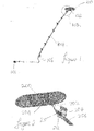
- Figure 1 shows a typical set up with a piece of equipment 100 (for example an antenna mounting) connected at one end 101 to a connection (for example, an electrical connection) and to a far end 102 by a cable 103.
- a connection for example, an electrical connection
- the cable is placed within a conduit 104 (a routing conduit) which extends from the ground 105 to the position of the equipment.
- the (far) end of the cable 102 is continually under tension which can affect the connection of the connector.
- the rubberised bung provides some relief from this but suffers from the inherent problems identified above. As a result, a need exists for a new type of conduit and stopper for preventing the tensions on the connector in any environment.
- One object of the present invention is to provide a cable stopper which overcomes at least some of the problems of the prior art rubberised bungs.
- a stopper for attachment to a cable the cable being intended to be inserted in to a conduit; the stopper comprising: an internal hole intended to accommodate the cable and an outer surface of which at least a part is adapted to conform to the geometry of an end of the conduit; wherein the stopper is formed in one or more parts from a plastics material (a plastic); and in use the stopper is fitted within the conduit and is able to move with a degree of angular articulation.
- the stopper has a circular cross-section.
- the stopper is oval in shape.
- the stopper comprises a gripping mechanism to hold the stopper in a predetermined position on the cable.
- the gripping mechanism comprises one or more of a gripping member and adhesive.
- the stopper is made of a single part bonded to the cable in the manufacture thereof.
- the stopper comprises two or more parts adapted to be connected together in use around the cable at a predetermined location.
- the stopper is made of two parts.
- the stopper includes a hinge along one edge.
- the two parts are adapted to snap together around the cable in use.
- the stopper includes a one or more grooves in the surface area for receiving a fastener that can be tensioned to hold two or more parts together.
- the fastener is a zip-tie.
- a cable including a stopper according to another aspect of the present invention.
- conduit adapted to accommodate a cable having a stopper according to another aspect of the present invention.
- a method of manufacturing a stopper for use with a cable to be inserted in a conduit having a predetermined geometry at an end thereof comprises: determining a shape of the predetermined geometry of the conduit; forming the stopper of one or two parts of a plastics material having at least a part conforming to the geometry of the conduit; and attaching the stopper to the cable.
- a piece of equipment 200 (for example an antenna mounting plinth) is shown connected to a cable 202 by means of a connector 204.
- Part of the cable is held within a conduit 206 which may be secured to a surface in the vicinity of the equipment by a mounting 208.
- a stopper 210 is located at the top end of the conduit 206 and fits within the opening to hold the cable in a desired position.
- the top of the conduit has a flared top section to accommodate the shape of the stopper.
- the stopper of the present invention sits in the top of the flared conduit geometry and stops any cable loads being transferred to the connector. The cable does remain relatively flat and the movement of the cable relative to the equipment does not disengage the connector.
- the stopper is adapted to be shaped so that it sits correctly within the geometry of the conduit.
- the shape of the conduit is any predetermined shape which can hold the stopper and support the cable to prevent the cable being damaged and to enable the tension in the cable to be dissipated so that the connector is not pulled out of the connection.
- the connector and stopper of the present invention can be used on any equipment installation on any platform that may have adverse conditions in the service life of the cable or connector. Such conditions may include high gravitational forces and aggressive vibration coupled with increased temperature ranges.
- the invention does promote a rugged nature of equipment installation and avoids failures and potentially increases service life.
- the invention is applicable to any environment where equipment needs to be connected to a cable housed within a conduit. Typical examples of such environment might be on an aircraft, a boat or a land vehicle of any type. However, this is not intended to be a limitation to the possible use of the present invention.
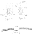
- the stopper 300 is shown in greater detail.
- the figures include a number of general dimensions and angles. These dimensions are not intended to be limitative and are shown only by way of example.
- the stopper has a circular cross section; and is tapered at either end as shown in figure 3A .
- the shape of the taper on either end is intended to accommodate the conduit geometry 302 as shown in figure 3A .
- the body of the stopper includes a number of grooves or holes intended to secure the stopper to the cable and to ensure that there is a tight fit around the cable.
- the stopper may be made in two halves as shown in figure 5 and then connected together by means of a fastener. This will be described in greater detail below.
- an injection port 304 is provided to allow for consistent injection of adhesive.
- Suitable adhesives are epoxy adhesives such as a two-part room temperature cure epoxy adhesive (for example MasterBond's ® EP31 or EP42HT-2LO).
- An annular ring feature 306 is used to allow for even consistent distribution of adhesive around the cable when the stopper is fixed to the cable in the manufacturing process. The stopper can thus be bonded on to the cable during manufacture and permanently fixed in position. Manufacture of the cable with the integrated stopper is one example of how the stopper can be used in conjunction with the cable. However, other manners in which the cable and stopper can be combined are also intended to be included in the present invention.
- the stopper comprises at least one plastic (for example a thermoset plastic or thermoplastic).
- the plastic is a thermoplastic with a glass transition temperature (T g ) of from about 50°C to 250°C, 50°C to 200°C, 50°C to 175°C, 50°C to 150°C, 50°C to 150°C).
- T g glass transition temperature
- the plastic may have a T g in excess of about 40°C, 50°C, 60°C, 70°C, 80°C, 90°C, 100°C, 110°C, or 120°C.
- the at least one plastic also preferably has a melting temperature in excess of 150°C, more preferably in excess of about 160, 170, 180, 190, 200, 210, 220, 230, 240, 250, 260, 270, 280, 290 or 300 °C.
- the stopper may be manufactured from a plastic such as a nylon (for example polyamide (nylon) 6.6), a polyaryletherketone, such as polyetheretherketone (PEEK) or a polycarbonate. Any other similar type of material can be used.
- the stopper could be made from a metal or metal alloy such as aluminium, steel or brass or any such metal/metal alloy with abrasive resistance.
- the material is intended to be of a type that would not be affected by exposure to temperature (for example above temperatures of about 80 °C) or frequent heat cycles and therefore would not slip within, or stick to, the conduit as has been a problem of prior art bungs.
- the shape of the stopper is designed to fit with a predetermined conduit having a predetermined shape at the end thereof.
- the use of a conduit having a flare or other conduit geometry, as described above allows a degree of angular articulation as the cable exits the conduit.
- the use of the curved edge as described above avoids any sharp edges near the bend radius in the cable and therefore there is less likelihood of the cable being damaged by the edge of the conduit.
- the conduit is shown having circular cross section and an elongated overall form. However, it will be appreciated that different shapes and cross sections are equally usable as long as the conduit is of a substantially corresponding shape. Examples of different shapes include cubes, squares and any other appropriate geometrical shape.
- FIG. 4 shows the stopper adhered to the cable during its manufacture as a one part plastic moulding.
- the stopper may grip the cable via a gripping mechanism, methods or processes other than adhesive.
- the internal surface of the stopper may include gripping members which grip the cable and hold the stopper in the required location along the cable and stop the stopper from moving in location in the conduit.
- the stopper may be manufactured so that it can be fitted or retrofitted to a cable after the cable has been manufactured.
- the stopper is formed of two or more parts 500 and 502.
- the two parts include a number of grooves 504 which are intended to enable the stopper to be connected together.
- the two parts of the stopper 500 and 502 can be combined together by means of a zip-tie 600. It will be appreciated that as there are two grooves in the example shown there may be two zip connectors 600. However, in other embodiments a single zip connector may be sufficient.
- the stopper could be manufactured as two halves that have a hinge down one side and snapped together around the cable to allow fitment after cable manufacture. This approach would encompass a self-locking feature to keep the stopper in a closed condition and clamped to the cable.
- the stopper could be assembled around the cable using two half components secured using standard zip-ties as previously described. This could be used in conjunction with a series of annular gripping features within the stopper to aid secure placement of the stopper relative to the cable.
- the annular gripping feature could be used on any of the different embodiments described above.
- An advantage of having a removable, two part fastener is that the stopper could be removed and repositioned either during installation or after installation as required. Adjustment in this way means that the benefits of the present invention can be realised by adjustment if the initial positioning of the stopper on the cable is not in the right position.
- grooves 504 and a zip fastener 600 would be to include a number of small fasteners to connect the two halves together. These fasteners may be of any appropriate nature and include small screws and other types of fastening.
- the conduit 700 is shown with a flared end 702.
- the stopper 700 is shown in position within the flared opening of the conduit 700.
- the conduit may be any shape or size and used in any environment.
- the opening at the end of the conduit may be any shape or size and the stopper is ideally adapted to cooperate with the geometry of the opening so that the required articulation of the "joint" between the cable and the conduit is achieved.
- the joint is the point of contact between the conduit end and the stopper, which allows movement of the cable and as necessary absorbs the forces that might disengage the connector from the equipment to which it is connected.
- the forces are essentially absorbed by the degree of articulation which occurs at the joint. That articulation will depend on the relative shapes of the stopper and conduit and the intrinsic local forces. One such force is generated by the weight of the cable relative to the location on the connector and the conduit.
- the stopper is shown entirely surrounding the cable however it will be appreciated that in certain circumstances two parts of the stopper could only partially surround the cable leaving gaps in the stopper that are not in contact with the cable and/or the conduit, in use. In this situation, the gripping features could be located at the edges of the parts of the stopper to ensure that they do not move relative to the cable towards one and other.
- stopper may be made of more than two parts and may be made up of many different parts connected together in which of a manner makes sense for the nature of the conduit.
- the stopper is formed of one or more parts as required by the design.
- the stopper is attached to the cable. As previously indicated this may be part of the manufacturing process of the cable. Alternatively, this may be a separate process from the manufacturer of the cable where the stopper is retrofitted to the cable after the cable has been manufactured. In this second case attachment of the stopper may be made by means of an appropriate fasten mechanism as discussed above. This fasten mechanism may include zip-ties, screws or other types of fastening.
- the stopper and cable are inserted into the conduit.
- the integrated cable and conduit is ready for use and the cable may be connected to whatever equipment is required.
Landscapes
- Engineering & Computer Science (AREA)
- Architecture (AREA)
- Civil Engineering (AREA)
- Structural Engineering (AREA)
- Installation Of Indoor Wiring (AREA)
Abstract
A stopper for attachment to a cable, the cable being intended to be inserted in to a conduit; the stopper comprising: an internal hole intended to accommodate the cable and an outer surface of which at least a part is adapted to conform to the geometry of an end of the conduit; wherein the stopper is formed in one or more parts from a plastics material; and in use the stopper is fitted within the conduit and is able to move with a degree of angular articulation.
Description
- The present invention relates to a cable position stopper for use in the positioning and installation of a cable and connectors to a piece of equipment.
- When installing equipment it is common to connect cables and connectors to the equipment. The position of the equipment can make the connection and/or the positioning of the cable difficult to install. The equipment may be positioned in a place which means that the weight of the cable pulls down on the connector. This problem can be exacerbated by adverse operating conditions. One way of reducing the effect of the tension on the connector is to place the cable in a conduit, often of metal, between the equipment and the other end of the cable. In order to stop the cable moving relative to the conduit it is traditional to use a potted bung positioned within, or at the end of, the conduit to prevent the cable from moving.
- The potted bung is traditionally made from a rubberised compound. The use of such rubberised bungs does not always provide the necessary positional accuracy required for the consistent life of the cable. In addition, the rubberised materials tend to bond themselves to the metal component of the conduit when in constant contact and particularly when put through elevated heat cycles. This leads to the cable becoming stuck within the conduit and the effect of the conduit being less useful in terms of reducing the tension in the connector.
-
Figure 1 shows a typical set up with a piece of equipment 100 (for example an antenna mounting) connected at oneend 101 to a connection (for example, an electrical connection) and to a farend 102 by acable 103. At a certain point the cable is placed within a conduit 104 (a routing conduit) which extends from theground 105 to the position of the equipment. The (far) end of thecable 102 is continually under tension which can affect the connection of the connector. The rubberised bung provides some relief from this but suffers from the inherent problems identified above. As a result, a need exists for a new type of conduit and stopper for preventing the tensions on the connector in any environment. - One object of the present invention is to provide a cable stopper which overcomes at least some of the problems of the prior art rubberised bungs.
- According to an aspect of the present invention there is provided a stopper for attachment to a cable, the cable being intended to be inserted in to a conduit; the stopper comprising: an internal hole intended to accommodate the cable and an outer surface of which at least a part is adapted to conform to the geometry of an end of the conduit; wherein the stopper is formed in one or more parts from a plastics material (a plastic); and in use the stopper is fitted within the conduit and is able to move with a degree of angular articulation.
- Preferably, the stopper has a circular cross-section.
- Preferably, the stopper is oval in shape.
- Preferably, the stopper comprises a gripping mechanism to hold the stopper in a predetermined position on the cable.
- Preferably, the gripping mechanism comprises one or more of a gripping member and adhesive.
- Preferably, the stopper is made of a single part bonded to the cable in the manufacture thereof.
- Preferably, the stopper comprises two or more parts adapted to be connected together in use around the cable at a predetermined location.
- Preferably, the stopper is made of two parts.
- Preferably, the stopper includes a hinge along one edge.
- Preferably, the two parts are adapted to snap together around the cable in use.
- Preferably, the stopper includes a one or more grooves in the surface area for receiving a fastener that can be tensioned to hold two or more parts together.
- Preferably, the fastener is a zip-tie.
- According to an aspect of the present invention there is provided a cable, including a stopper according to another aspect of the present invention.
- According to an aspect of the present invention there is provided a conduit adapted to accommodate a cable having a stopper according to another aspect of the present invention.
- According to an aspect of the present invention there is provided a combination of a conduit according to an aspect of the present invention, a cable according to an aspect of the present invention and a stopper to an aspect of the present invention.
- According to an aspect of the present invention there is provided a method of manufacturing a stopper for use with a cable to be inserted in a conduit having a predetermined geometry at an end thereof, the method comprises: determining a shape of the predetermined geometry of the conduit; forming the stopper of one or two parts of a plastics material having at least a part conforming to the geometry of the conduit; and attaching the stopper to the cable.
-
-
Figure 1 shows a prior art cable and equipment connected in a particular environment. -
Figure 2 is a view of a connector and cable conduit according to one aspect of the present invention. -
Figures 3A and 3B are design drawings of the cable stopper, according to an embodiment of the present invention. -
Figure 4 is a diagram showing the cable stopper in place on a cable, according to an embodiment of the present invention. -
Figure 5 is a diagram showing the cable stopper in two parts which can be combined together, according to an embodiment of the present invention. -
Figure 6 is a diagram showing the cable stopper in two parts combined together, according to an embodiment of the present invention. -
Figure 7 shows a cable stopper in situ in a conduit, according to an embodiment of the present invention. -
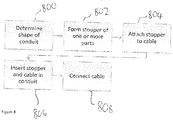
Figure 8 is a flow chart showing a method of manufacture of the stopper, according to an embodiment of the present invention. - According to
figure 2 a piece of equipment 200 (for example an antenna mounting plinth) is shown connected to acable 202 by means of aconnector 204. Part of the cable is held within a conduit 206 which may be secured to a surface in the vicinity of the equipment by a mounting 208. Astopper 210 is located at the top end of the conduit 206 and fits within the opening to hold the cable in a desired position. The top of the conduit has a flared top section to accommodate the shape of the stopper. To be more precise the stopper of the present invention sits in the top of the flared conduit geometry and stops any cable loads being transferred to the connector. The cable does remain relatively flat and the movement of the cable relative to the equipment does not disengage the connector. - The stopper is adapted to be shaped so that it sits correctly within the geometry of the conduit. The shape of the conduit is any predetermined shape which can hold the stopper and support the cable to prevent the cable being damaged and to enable the tension in the cable to be dissipated so that the connector is not pulled out of the connection.
- The connector and stopper of the present invention can be used on any equipment installation on any platform that may have adverse conditions in the service life of the cable or connector. Such conditions may include high gravitational forces and aggressive vibration coupled with increased temperature ranges. The invention does promote a rugged nature of equipment installation and avoids failures and potentially increases service life. The invention is applicable to any environment where equipment needs to be connected to a cable housed within a conduit. Typical examples of such environment might be on an aircraft, a boat or a land vehicle of any type. However, this is not intended to be a limitation to the possible use of the present invention.
- Referring to
figures 3A and 3B thestopper 300 is shown in greater detail. The figures include a number of general dimensions and angles. These dimensions are not intended to be limitative and are shown only by way of example. As can be seen fromfigure 3B the stopper has a circular cross section; and is tapered at either end as shown infigure 3A . The shape of the taper on either end is intended to accommodate theconduit geometry 302 as shown infigure 3A . - The body of the stopper includes a number of grooves or holes intended to secure the stopper to the cable and to ensure that there is a tight fit around the cable. To this end, the stopper may be made in two halves as shown in
figure 5 and then connected together by means of a fastener. This will be described in greater detail below. - In the case of a one-piece design, an
injection port 304 is provided to allow for consistent injection of adhesive. Suitable adhesives are epoxy adhesives such as a two-part room temperature cure epoxy adhesive (for example MasterBond's® EP31 or EP42HT-2LO). Anannular ring feature 306 is used to allow for even consistent distribution of adhesive around the cable when the stopper is fixed to the cable in the manufacturing process. The stopper can thus be bonded on to the cable during manufacture and permanently fixed in position. Manufacture of the cable with the integrated stopper is one example of how the stopper can be used in conjunction with the cable. However, other manners in which the cable and stopper can be combined are also intended to be included in the present invention. - The stopper comprises at least one plastic (for example a thermoset plastic or thermoplastic). Preferably the plastic is a thermoplastic with a glass transition temperature (Tg) of from about 50°C to 250°C, 50°C to 200°C, 50°C to 175°C, 50°C to 150°C, 50°C to 150°C). The plastic may have a Tg in excess of about 40°C, 50°C, 60°C, 70°C, 80°C, 90°C, 100°C, 110°C, or 120°C. The at least one plastic also preferably has a melting temperature in excess of 150°C, more preferably in excess of about 160, 170, 180, 190, 200, 210, 220, 230, 240, 250, 260, 270, 280, 290 or 300 °C. For example, the stopper may be manufactured from a plastic such as a nylon (for example polyamide (nylon) 6.6), a polyaryletherketone, such as polyetheretherketone (PEEK) or a polycarbonate. Any other similar type of material can be used. Indeed, the stopper could be made from a metal or metal alloy such as aluminium, steel or brass or any such metal/metal alloy with abrasive resistance. The material is intended to be of a type that would not be affected by exposure to temperature (for example above temperatures of about 80 °C) or frequent heat cycles and therefore would not slip within, or stick to, the conduit as has been a problem of prior art bungs. The shape of the stopper is designed to fit with a predetermined conduit having a predetermined shape at the end thereof. The use of a conduit having a flare or other conduit geometry, as described above allows a degree of angular articulation as the cable exits the conduit. In addition, the use of the curved edge as described above, avoids any sharp edges near the bend radius in the cable and therefore there is less likelihood of the cable being damaged by the edge of the conduit.
- The conduit is shown having circular cross section and an elongated overall form. However, it will be appreciated that different shapes and cross sections are equally usable as long as the conduit is of a substantially corresponding shape. Examples of different shapes include cubes, squares and any other appropriate geometrical shape.
- As previously mentioned
figure 4 shows the stopper adhered to the cable during its manufacture as a one part plastic moulding. The stopper may grip the cable via a gripping mechanism, methods or processes other than adhesive. For example, the internal surface of the stopper may include gripping members which grip the cable and hold the stopper in the required location along the cable and stop the stopper from moving in location in the conduit. - Referring to
figure 5 , as previously suggested the stopper may be manufactured so that it can be fitted or retrofitted to a cable after the cable has been manufactured. In this case, the stopper is formed of two ormore parts 500 and 502. In the illustrated example, the two parts include a number ofgrooves 504 which are intended to enable the stopper to be connected together. As shown infigure 6 the two parts of thestopper 500 and 502 can be combined together by means of a zip-tie 600. It will be appreciated that as there are two grooves in the example shown there may be twozip connectors 600. However, in other embodiments a single zip connector may be sufficient. - The stopper could be manufactured as two halves that have a hinge down one side and snapped together around the cable to allow fitment after cable manufacture. This approach would encompass a self-locking feature to keep the stopper in a closed condition and clamped to the cable. The stopper could be assembled around the cable using two half components secured using standard zip-ties as previously described. This could be used in conjunction with a series of annular gripping features within the stopper to aid secure placement of the stopper relative to the cable. The annular gripping feature could be used on any of the different embodiments described above.
- An advantage of having a removable, two part fastener is that the stopper could be removed and repositioned either during installation or after installation as required. Adjustment in this way means that the benefits of the present invention can be realised by adjustment if the initial positioning of the stopper on the cable is not in the right position.
- An alternative to using
grooves 504 and azip fastener 600 would be to include a number of small fasteners to connect the two halves together. These fasteners may be of any appropriate nature and include small screws and other types of fastening. - Referring now to
figure 7 , theconduit 700 is shown with a flaredend 702. Thestopper 700 is shown in position within the flared opening of theconduit 700. As previously indicated the conduit may be any shape or size and used in any environment. The opening at the end of the conduit may be any shape or size and the stopper is ideally adapted to cooperate with the geometry of the opening so that the required articulation of the "joint" between the cable and the conduit is achieved. The joint is the point of contact between the conduit end and the stopper, which allows movement of the cable and as necessary absorbs the forces that might disengage the connector from the equipment to which it is connected. The forces are essentially absorbed by the degree of articulation which occurs at the joint. That articulation will depend on the relative shapes of the stopper and conduit and the intrinsic local forces. One such force is generated by the weight of the cable relative to the location on the connector and the conduit. - In the various embodiments shown above the stopper is shown entirely surrounding the cable however it will be appreciated that in certain circumstances two parts of the stopper could only partially surround the cable leaving gaps in the stopper that are not in contact with the cable and/or the conduit, in use. In this situation, the gripping features could be located at the edges of the parts of the stopper to ensure that they do not move relative to the cable towards one and other.
- It should be noted that the stopper may be made of more than two parts and may be made up of many different parts connected together in which of a manner makes sense for the nature of the conduit.
- Referring to
figure 8 , a method of manufacturing a cable for connection to equipment will now be described. In the first step 800 a determination is made of the shape of the conduit and the expected location of the stopper. Atstep 802 the stopper is formed of one or more parts as required by the design. Atstep 804 the stopper is attached to the cable. As previously indicated this may be part of the manufacturing process of the cable. Alternatively, this may be a separate process from the manufacturer of the cable where the stopper is retrofitted to the cable after the cable has been manufactured. In this second case attachment of the stopper may be made by means of an appropriate fasten mechanism as discussed above. This fasten mechanism may include zip-ties, screws or other types of fastening. Atstep 806 the stopper and cable are inserted into the conduit. Atstep 808 the integrated cable and conduit is ready for use and the cable may be connected to whatever equipment is required. - Although the present invention has been described in connection with some embodiments, it is not intended to be limited to the specific form set forth herein. Rather, the scope of the present invention is limited only by the accompanying claims. Additionally, although a feature may appear to be described in connection with particular embodiments, one skilled in the art would recognize that various features of the described embodiments may be combined in accordance with the invention. In the claims, the term 'comprising' does not exclude the presence of other elements or steps.
- Furthermore, the order of features in the claims does not imply any specific order in which the features must be performed and in particular the order of individual steps in a method claim does not imply that the steps must be performed in this order. Rather, the steps may be performed in any suitable order. In addition, singular references do not exclude a plurality. Thus, references to 'a', 'an', 'first', 'second', etc. do not preclude a plurality. In the claims, the term 'comprising' or "including" does not exclude the presence of other elements.
Claims (16)
- A stopper for attachment to a cable, the cable being intended to be inserted in to a conduit; the stopper comprising: an internal hole intended to accommodate the cable and an outer surface of which at least a part is adapted to conform to the geometry of an end of the conduit; wherein the stopper is formed in one or more parts from a plastic; and in use the stopper is fitted within the conduit and is able to move with a degree of angular articulation.
- The stopper according to claim 1, wherein the stopper has a circular cross-section.
- The stopper according to claim 1 or 2, wherein the stopper is oval in shape.
- The stopper according to any one of claims 1 to 3, wherein the stopper comprises a gripping mechanism to hold the stopper in a predetermined position on the cable.
- The stopper according to claim 4, wherein the gripping mechanism comprises one or more of a gripping member and adhesive.
- The stopper according to any one of claims 1 to 5, wherein the stopper is made of a single part bonded to the cable in the manufacture thereof.
- The stopper according to any one of claims 1 to 5, wherein the stopper comprises two or more parts adapted to be connected together in use around the cable at a predetermined location.
- The stopper according to claim 7, wherein the stopper is made of two parts.
- The stopper according to claim 7 or 8, wherein the stopper includes a hinge along one edge.
- The stopper according to any one of claims 7 to 9, wherein the two parts are adapted to snap together around the cable in use.
- The stopper according to any one of claims 7 to 9, wherein the stopper includes one or more grooves in the surface area for receiving a fastener that can be tensioned to hold the two or more parts together.
- The stopper according to claim 11, wherein the fastener is a zip-tie.
- A cable, including a stopper according to any one of the preceding claims.
- A conduit adapted to accommodate a cable having a stopper according to any one of claims 1 to 12.
- A combination of a conduit according to claim 14, a cable according to claim 13 and a stopper according to any one of claims 1 to 12.
- A method of manufacturing a stopper for use with a cable to be inserted in a conduit having a predetermined geometry at an end thereof, wherein the method comprises:determining a shape of the predetermined geometry of the conduit;forming the stopper of one or two parts of a plastics material having at least a part conforming to the geometry of the conduit; andattaching the stopper to the cable.
Priority Applications (6)
| Application Number | Priority Date | Filing Date | Title |
|---|---|---|---|
| EP17184351.9A EP3439126A1 (en) | 2017-08-01 | 2017-08-01 | Cable position stopper |
| EP18749480.2A EP3662549A1 (en) | 2017-08-01 | 2018-07-30 | Cable position stopper |
| GB1812361.2A GB2565232B (en) | 2017-08-01 | 2018-07-30 | Cable position stopper |
| US16/635,825 US11183820B2 (en) | 2017-08-01 | 2018-07-30 | Cable position stopper |
| PCT/GB2018/052155 WO2019025772A1 (en) | 2017-08-01 | 2018-07-30 | CABLE POSITION CAP |
| SA520411196A SA520411196B1 (en) | 2017-08-01 | 2020-01-30 | Cable Position Stopper |
Applications Claiming Priority (1)
| Application Number | Priority Date | Filing Date | Title |
|---|---|---|---|
| EP17184351.9A EP3439126A1 (en) | 2017-08-01 | 2017-08-01 | Cable position stopper |
Publications (1)
| Publication Number | Publication Date |
|---|---|
| EP3439126A1 true EP3439126A1 (en) | 2019-02-06 |
Family
ID=59581721
Family Applications (1)
| Application Number | Title | Priority Date | Filing Date |
|---|---|---|---|
| EP17184351.9A Ceased EP3439126A1 (en) | 2017-08-01 | 2017-08-01 | Cable position stopper |
Country Status (1)
| Country | Link |
|---|---|
| EP (1) | EP3439126A1 (en) |
Citations (5)
| Publication number | Priority date | Publication date | Assignee | Title |
|---|---|---|---|---|
| US4300665A (en) * | 1980-04-25 | 1981-11-17 | Ametek, Inc. | Switch device for self-retracting cord reel |
| DE4225267A1 (en) * | 1992-03-19 | 1993-09-23 | Ifm Electronic Gmbh | Electronic proximity switch wing tubular housing - has stopper at one housing side with cable bushing of meltable adhesive |
| EP0715385A1 (en) * | 1994-12-02 | 1996-06-05 | The Whitaker Corporation | Improved strain relief member for insulated cable |
| WO2005081375A1 (en) * | 2004-02-25 | 2005-09-01 | Appulia Ltd | A cable entry device for easy installation |
| US9425604B1 (en) * | 2013-12-13 | 2016-08-23 | James Brooks Lawrence | Adjustable electrical cord connector protection device |
-
2017
- 2017-08-01 EP EP17184351.9A patent/EP3439126A1/en not_active Ceased
Patent Citations (5)
| Publication number | Priority date | Publication date | Assignee | Title |
|---|---|---|---|---|
| US4300665A (en) * | 1980-04-25 | 1981-11-17 | Ametek, Inc. | Switch device for self-retracting cord reel |
| DE4225267A1 (en) * | 1992-03-19 | 1993-09-23 | Ifm Electronic Gmbh | Electronic proximity switch wing tubular housing - has stopper at one housing side with cable bushing of meltable adhesive |
| EP0715385A1 (en) * | 1994-12-02 | 1996-06-05 | The Whitaker Corporation | Improved strain relief member for insulated cable |
| WO2005081375A1 (en) * | 2004-02-25 | 2005-09-01 | Appulia Ltd | A cable entry device for easy installation |
| US9425604B1 (en) * | 2013-12-13 | 2016-08-23 | James Brooks Lawrence | Adjustable electrical cord connector protection device |
Non-Patent Citations (1)
| Title |
|---|
| HANNAY REELS: "Hannay Reels Hose & Cable Stops - Dultmeier Sales", 19 October 2008 (2008-10-19), XP055447850, Retrieved from the Internet <URL:https://web.archive.org/web/20081019083115/https://www.dultmeier.com/products/0.698.1048.2265/1779> [retrieved on 20180205] * |
Similar Documents
| Publication | Publication Date | Title |
|---|---|---|
| EP2016811B1 (en) | Adjustable mounting bracket | |
| US8991774B2 (en) | Cable tie mount | |
| USRE39448E1 (en) | Connecting device for connecting a fan blade to a rotor of a motor of a ceiling fan | |
| US9376791B2 (en) | Faucet assemblies | |
| US10125803B2 (en) | Fixing device for lower level member and fluid control apparatus provided with the same | |
| EP3589873B1 (en) | Hose mounting assembly | |
| US9534706B2 (en) | Subsea system for mounting a cable to a pipeline | |
| US20150323101A1 (en) | Line clamp assembly and method of use | |
| US20190271343A1 (en) | Height adjustable magnet fastener | |
| JP5060286B2 (en) | Coaxially coated fuel pipe spacer | |
| US6825417B2 (en) | Slide and snap cable end fitting | |
| US7614602B2 (en) | Standoff attachment with internal nut | |
| US20090016843A1 (en) | Spacer Assemblies, Apparatus and Methods of Supporting Hardware | |
| US11183820B2 (en) | Cable position stopper | |
| EP2777991B1 (en) | Multifunctional adaptor | |
| US8092133B2 (en) | Device and method for mounting objects on a vehicle wall | |
| US20110180320A1 (en) | Bracket for attaching an electrical cable to a vehicle | |
| KR101599804B1 (en) | Checking apparatus of pipe insertion and method of connecting a pipe to a target object | |
| US8925866B2 (en) | Device for fastening systems for an aircraft, adapted in particular to be used in relation to a window | |
| US11927035B2 (en) | Sheath end piece for vehicle opening cable | |
| US20150162733A1 (en) | Grommet with spreader mounting feature | |
| US12546354B1 (en) | Safety anchoring accessory | |
| KR20150026659A (en) | Checking apparatus of pipe insertion | |
| US20150059513A1 (en) | Insert for securing cables, cable lines and wires in a bicycle frame | |
| US20080029582A1 (en) | Positive hold tube weld stud assembly |
Legal Events
| Date | Code | Title | Description |
|---|---|---|---|
| PUAI | Public reference made under article 153(3) epc to a published international application that has entered the european phase |
Free format text: ORIGINAL CODE: 0009012 |
|
| AK | Designated contracting states |
Kind code of ref document: A1 Designated state(s): AL AT BE BG CH CY CZ DE DK EE ES FI FR GB GR HR HU IE IS IT LI LT LU LV MC MK MT NL NO PL PT RO RS SE SI SK SM TR |
|
| AX | Request for extension of the european patent |
Extension state: BA ME |
|
| STAA | Information on the status of an ep patent application or granted ep patent |
Free format text: STATUS: THE APPLICATION HAS BEEN REFUSED |
|
| 18R | Application refused |
Effective date: 20190225 |