EP3439010B1 - Water fullness alarm device for dehumidifier - Google Patents
Water fullness alarm device for dehumidifier Download PDFInfo
- Publication number
- EP3439010B1 EP3439010B1 EP16896188.6A EP16896188A EP3439010B1 EP 3439010 B1 EP3439010 B1 EP 3439010B1 EP 16896188 A EP16896188 A EP 16896188A EP 3439010 B1 EP3439010 B1 EP 3439010B1
- Authority
- EP
- European Patent Office
- Prior art keywords
- float
- bracket
- alarm device
- elastic piece
- water
- Prior art date
- Legal status (The legal status is an assumption and is not a legal conclusion. Google has not performed a legal analysis and makes no representation as to the accuracy of the status listed.)
- Active
Links
Images




Classifications
-
- G—PHYSICS
- G01—MEASURING; TESTING
- G01F—MEASURING VOLUME, VOLUME FLOW, MASS FLOW OR LIQUID LEVEL; METERING BY VOLUME
- G01F23/00—Indicating or measuring liquid level or level of fluent solid material, e.g. indicating in terms of volume or indicating by means of an alarm
- G01F23/30—Indicating or measuring liquid level or level of fluent solid material, e.g. indicating in terms of volume or indicating by means of an alarm by floats
- G01F23/32—Indicating or measuring liquid level or level of fluent solid material, e.g. indicating in terms of volume or indicating by means of an alarm by floats using rotatable arms or other pivotable transmission elements
-
- G—PHYSICS
- G01—MEASURING; TESTING
- G01F—MEASURING VOLUME, VOLUME FLOW, MASS FLOW OR LIQUID LEVEL; METERING BY VOLUME
- G01F23/00—Indicating or measuring liquid level or level of fluent solid material, e.g. indicating in terms of volume or indicating by means of an alarm
- G01F23/30—Indicating or measuring liquid level or level of fluent solid material, e.g. indicating in terms of volume or indicating by means of an alarm by floats
- G01F23/32—Indicating or measuring liquid level or level of fluent solid material, e.g. indicating in terms of volume or indicating by means of an alarm by floats using rotatable arms or other pivotable transmission elements
- G01F23/34—Indicating or measuring liquid level or level of fluent solid material, e.g. indicating in terms of volume or indicating by means of an alarm by floats using rotatable arms or other pivotable transmission elements using mechanically actuated indicating means
-
- H—ELECTRICITY
- H01—ELECTRIC ELEMENTS
- H01H—ELECTRIC SWITCHES; RELAYS; SELECTORS; EMERGENCY PROTECTIVE DEVICES
- H01H35/00—Switches operated by change of a physical condition
- H01H35/18—Switches operated by change of liquid level or of liquid density, e.g. float switch
-
- F—MECHANICAL ENGINEERING; LIGHTING; HEATING; WEAPONS; BLASTING
- F24—HEATING; RANGES; VENTILATING
- F24F—AIR-CONDITIONING; AIR-HUMIDIFICATION; VENTILATION; USE OF AIR CURRENTS FOR SCREENING
- F24F11/00—Control or safety arrangements
- F24F11/30—Control or safety arrangements for purposes related to the operation of the system, e.g. for safety or monitoring
-
- F—MECHANICAL ENGINEERING; LIGHTING; HEATING; WEAPONS; BLASTING
- F24—HEATING; RANGES; VENTILATING
- F24F—AIR-CONDITIONING; AIR-HUMIDIFICATION; VENTILATION; USE OF AIR CURRENTS FOR SCREENING
- F24F3/00—Air-conditioning systems in which conditioned primary air is supplied from one or more central stations to distributing units in the rooms or spaces where it may receive secondary treatment; Apparatus specially designed for such systems
- F24F3/12—Air-conditioning systems in which conditioned primary air is supplied from one or more central stations to distributing units in the rooms or spaces where it may receive secondary treatment; Apparatus specially designed for such systems characterised by the treatment of the air otherwise than by heating and cooling
- F24F3/14—Air-conditioning systems in which conditioned primary air is supplied from one or more central stations to distributing units in the rooms or spaces where it may receive secondary treatment; Apparatus specially designed for such systems characterised by the treatment of the air otherwise than by heating and cooling by humidification; by dehumidification
-
- F—MECHANICAL ENGINEERING; LIGHTING; HEATING; WEAPONS; BLASTING
- F24—HEATING; RANGES; VENTILATING
- F24F—AIR-CONDITIONING; AIR-HUMIDIFICATION; VENTILATION; USE OF AIR CURRENTS FOR SCREENING
- F24F11/00—Control or safety arrangements
- F24F11/89—Arrangement or mounting of control or safety devices
-
- F—MECHANICAL ENGINEERING; LIGHTING; HEATING; WEAPONS; BLASTING
- F24—HEATING; RANGES; VENTILATING
- F24F—AIR-CONDITIONING; AIR-HUMIDIFICATION; VENTILATION; USE OF AIR CURRENTS FOR SCREENING
- F24F3/00—Air-conditioning systems in which conditioned primary air is supplied from one or more central stations to distributing units in the rooms or spaces where it may receive secondary treatment; Apparatus specially designed for such systems
- F24F3/12—Air-conditioning systems in which conditioned primary air is supplied from one or more central stations to distributing units in the rooms or spaces where it may receive secondary treatment; Apparatus specially designed for such systems characterised by the treatment of the air otherwise than by heating and cooling
- F24F3/14—Air-conditioning systems in which conditioned primary air is supplied from one or more central stations to distributing units in the rooms or spaces where it may receive secondary treatment; Apparatus specially designed for such systems characterised by the treatment of the air otherwise than by heating and cooling by humidification; by dehumidification
- F24F2003/144—Air-conditioning systems in which conditioned primary air is supplied from one or more central stations to distributing units in the rooms or spaces where it may receive secondary treatment; Apparatus specially designed for such systems characterised by the treatment of the air otherwise than by heating and cooling by humidification; by dehumidification by dehumidification only
Definitions
- the present invention relates to the technical field of dehumidification equipment, in particular, to a water fullness alarm device for a dehumidifier.
- the device for collecting water in a dehumidifier is a water collection tank.
- the water in the water collection tank reaches a certain amount, the user needs to be reminded to remove the water or the power of the dehumidifier will be directly cut off so as to prevent the water from overflowing from the water collection tank and damaging the indoor environment.
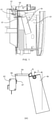
- FIG. 1 shows a dehumidifier In related art.
- the dehumidifier is provided with a water fullness alarm device.
- the water fullness alarm device includes a microswitch 02 fixed on a support frame 01, a trigger bar 04 passing through a dehumidifier housing 03, and a buoy 06 hinged in a water collection tank 05.
- a button 07 is provided on the microswitch 02, and an elastic piece 08 is pressed on the button.
- One end of the elastic piece 08 is fixed on the microswitch 02, and another end thereof is free; one end of the trigger bar 04 is propped against the elastic piece 08, and another end thereof is propped against one end of the buoy 06.
- the buoy 06 When there is less water in the water collection tank 05, the buoy 06, under the action of its own gravity, causes the trigger bar 04 to bear against the elastic piece 08 so as to bear against the microswitch 02. At this time, the dehumidifier is powered on. When the water in the water collection tank 05 reaches a certain amount, the buoy 06 floats upward as the water level rises, so that a force of the buoy 06 on the trigger bar 04 is reduced, and the trigger bar 04 and the microswitch 02 are separated. At this time, the dehumidifier is powered off. In this way, the water fullness alarm operation is realized.
- This structure is simple and easy to implement.
- the water fullness alarm device is composed of three parts - the microswitch 02, the trigger bar 04 and the buoy 06, and the trigger bar 04 is propped against both the microswitch 02 and the buoy 06, the connection structure is loose with a long dimensional chain. After a long time of use, frictional wear will occur between the trigger bar 04 and the elastic piece 08 on the microswitch 02, and between the trigger bar 04 and the buoy 06. The effects of frictional wear at the two places will add up and the obtained total frictional wear substantially reduce the transmission precision of the water fullness alarm device, therefore the reliability and stability of system response of the water fullness alarm device are low.
- D1( CN201373528Y ) discloses a water full protection device of a water tank which can avoid abnormal action.
- the water full protection device comprises a water tank, a buoy arranged in the water tank and a micro switch linked with the buoy.
- a top block is arranged on the buoy, the top block extends transversely and an upper end surface of the top block is downward inclined along the extension direction.
- a contact and a contact plate which can touch the contact under the effect of the top block are arranged on the micro switch.
- the end of the contact plate is provided with an arc-shaped hook.
- the upper end surface of the top block is always touched with the convex surface of the arc-shaped hook of the contact plate in sliding way during the movement of the buoy.
- the water full protection device is provided with the contact plate with the arc-shaped hook, and the contact plate is arranged along the vertical direction; the arc-shaped surface of the upper end of the top block is always touched with the arc-shaped hook of the contact plate in sliding way; when the buoy of the water tank is moved, the contact plate of the micro switch is also moved; and then, the circuit of the electric control system of the device is opened or closed accordingly, that is to say, the switch circuit can repeatedly carry out the reset action, thus avoiding the jamming or the misplacement phenomenon and improving the accuracy of the action.
- the present invention provides a water fullness alarm device for a dehumidifier, for use in improving the reliability and stability of the system response of the same.
- the present invention provides a water fullness alarm device for a dehumidifier, which comprises an alarm switch and a float; the alarm switch comprises a switch button covered with an elastic piece; one end of the elastic piece is fixed to the alarm switch, and another end is free.
- the water fullness alarm device further comprises a bracket that is rotatable; a first end of the bracket is connected with the float, and a second end of the bracket comprises a flange which is propped against the elastic piece. When the float floats upward, the second end of the bracket propped against the elastic piece can swing around a rotating axis of the bracket and drive the elastic piece to trigger the switch button.
- the flange is smooth and continuous and when the bracket swings around the rotating axis thereof, the elastic piece will always be propped against the flange. And as a rotation angle of the bracket gradually increases, a rate of change of a horizontal distance between the rotating axis of the bracket and a contact point between the flange and the elastic piece gradually increases.
- the float In the water fullness alarm device for a dehumidifier provided by the present invention, when the water level in the water collection tank reaches a certain level, the float will float upward as the water level rises, and push the bracket to swing around the rotating axis thereof; the second end of the bracket propped against the elastic piece can drive the elastic piece to trigger the switch button when swinging; and when the switch button is triggered, the alarm operation will be realized.
- the alarm is triggered through successive transmission between an elastic piece on the microswitch and a trigger bar, and between the trigger bar and a buoy.
- the alarm is triggered only through transmission between a bracket connected with a float and an elastic piece.
- the water fullness alarm device provided by the present disclosure has a simple and compact structure, a shorter dimensional chain, and higher reliability and stability of system response.
- orientations or positional relationships indicated by terms “center”, “upper”, “lower”, “front”, “rear”, “left”, “right”, “vertical”, “horizontal”, “top”, “bottom”, “inner”, “outer”, etc. are based on orientations or positional relationships shown in the drawings, merely to facilitate and simplify the description of the present invention, but not to indicate or imply that the referred devices or elements must have a particular orientation, or must be constructed or operated in a particular orientation. Therefore they should not be construed as limitations to the present invention.
- a water collection tank is provided in a dehumidifier, and the water collection tank can be taken out from a housing of the dehumidifier.
- a bracket is installed in the water collection tank, and an alarm switch and an elastic piece are disposed outside the housing of the dehumidifier.
- a first end of the bracket is located in the water collection tank and is connected with a float, and a second end of the bracket protrudes out of the housing and is propped against the elastic piece.
- FIG. 5 is anembodiment of a water fullness alarm device for a dehumidifier according to embodiments of the present invention.
- the water fullness alarm device for a dehumidifier includes an alarm switch 1, and the alarm switch 1 includes a switch button 2.
- the switch button 2 is covered with an elastic piece 3; one end of the elastic piece 3 is fixed, and another end is free.
- the water fullness alarm device further includes a bracket 4 that is rotatable; a first end of the bracket 4 is connected with a float 5, and a second end of the bracket 4 is propped against the elastic piece 3; when the float 5 floats upward, the end of the bracket 4 propped against the elastic piece 3 can swing around a rotating axis of the bracket and drive the elastic piece 3 to trigger the switch button 2.
- the water fullness alarm device for a dehumidifier for a dehumidifier
- the float 5 will float upward as the water level rises, and push the bracket 4 to swing around the rotating axis thereof; the second end of the bracket 4 propped against the elastic piece 3 can drive the elastic piece 3 to trigger the switch button 2 during the swinging of the bracket 4; and when the switch button 2 is triggered, an alarm operation will be realized.
- the alarm is triggered through successive transmission between the elastic piece on the microswitch and the trigger bar, and between the trigger bar and the buoy.
- the alarm is triggered only through transmission between the bracket 4 connected with the float 5 and the elastic piece 3.
- the water fullness alarm device provided by the present invention has a simple and compact structure, a shorter dimensional chain, and higher reliability and stability of system response of the water fullness alarm device.
- the alarm operation performed by the alarm switch 1 may be sending an alarm sound to remind the user that the water is full, or displaying a "water full" prompt on the display screen to remind the user that the water is full.
- the alarm operation may also be directly cutting off the switching power supply of the dehumidifier to stop the dehumidification operation.
- the alarm operation is not specifically limited herein, as long as the water fullness information can be transmitted to the user.
- the operation process of the switch button 2, the elastic piece 3, the bracket 4 and the float 5 is as follows: in the initial state, the float 5, under the action of its own gravity, causes the end of the bracket 4 propped against the elastic piece 3 to bear against the elastic piece 3 so as to bear against the switch button 2; when the water in the water collection tank rises gradually and reaches a certain level, the float 5 will float upward as the water level rises, so that a force from the end of the bracket 4 propped against the elastic piece 3 on the elastic piece 3 is reduced, and the elastic piece 3 is separated from the switch button 2 to trigger the alarm switch 1.
- a fixed end of the elastic piece 3 may be fixed to the alarm switch 1 as shown in FIG. 5 , or may be fixed on a support frame outside the housing of the dehumidifier, or may be fixed on the housing of the dehumidifier, which is not specifically limited herein, as long as the position of the fixed end of the elastic piece 3 is fixed relative to the alarm switch 1, the water collection tank and the rotating axis of the bracket 4.
- a vertical plane for convenience of description, containing the rotating axis of the bracket 4 is defined as a first plane.
- first plane a vertical plane, for convenience of description, containing the rotating axis of the bracket 4
- first end and the second end of the bracket 4 may be located on both sides of the first plane, or may be located on the same side of the first plane, which is not specifically limited herein, as long as the end of the bracket 4 propped against the elastic piece 3 can swing around the rotating axis of the bracket when the float 5 floats upward.
- both the first end and the second end of the bracket 4 will swing upward around the rotating axis of the bracket when the float 5 floats upward.
- an end of the buoy 06 propped against the trigger bar 04 is provided with a quarter arc surface, and a top end of the arc surface is formed with a sharp corner K.
- an end portion of the trigger bar 04 is propped against the arc surface.
- the buoy 06 floats upward, the buoy 06 can gently push the trigger bar 04 to move via the arc surface.
- the buoy 06 can be rotated counterclockwise by a large angle under the action of its own gravity, separating the end portion of the trigger bar 04 from the arc surface, and propping the sharp corner K at the top end of the arc surface against a side wall of the trigger bar 04 as shown in FIG. 2b .
- the dehumidifier is re-righted, as shown in FIG. 2c , the sharp corner K at the top end of the arc surface is still jammed on the side wall of the trigger bar 04 and it is difficult for the sharp corner K to return to the normal state.
- an alarm will be sent when the dehumidifier is turned on.
- the second end of the bracket 4 propped against the elastic piece can be constructed as shown in FIG. 5 , that is, a flange 41 is provided on the second end of the bracket 4 propped against the elastic piece 3, and a contour of the flange 41 is smooth and continuous; the elastic piece 3 will always be propped against the flange 41 when the bracket 4 swings around the rotating axis thereof.
- FIG. 6a when the dehumidifier is laid down, the bracket 4 is rotated counterclockwise by a large angle, but the elastic piece 3 is still propped against the flange 41.
- the elastic piece 3 can vertically disposed, and when there is a deviation in the height of the bracket 4, the elastic piece 3 will not swing, thereby ensuring the trigging accuracy of the alarm device and improving the ability of the alarm device to resist the interference of deviations. as shown in FIG. 5 .
- the relative positional deviation between the alarm switch 1 and the rotating axis of the bracket 4 is mainly considered.
- the relative positional deviation between the alarm switch 1 and the rotating axis of the bracket 4 includes deviation in the horizontal direction and deviation in the vertical direction. Since a position-limiting structure for ensuring the mounting accuracy in the horizontal direction is usually provided in the dehumidifier, as for the relative positional deviation between the alarm switch 1 and the rotating axis of the bracket 4, the deviation in the vertical direction is mainly considered.
- connection structure between the bracket 4 and the float 5 may be a structure as shown in FIG. 8 , that is, the first end of the bracket 4 connected with the float 5 is embedded in the interior of the float 5 for fixing.
- the connection structure between the bracket 4 and the float 5 may also be a structure as shown in FIG. 5 , that is, the first end of the bracket 4 connected with the float 5 is fixed with a float mounting box 6, the float mounting box 6 is provided with a mounting opening 7, and the float 5 can be connected to the float mounting box 6 through the mounting opening 7.
- the second solution can effectively fix the relative position of the float 5 and the bracket 4 by mounting the float 5 in the float mounting box 6, so as to prevent the float 5 from coming off the bracket 4.
- the mounting opening 7 is opened at a lower end of the float mounting box 6;
- the buoyancy direction of the float 5 is opposite to the direction in which the float 5 comes out of the mounting opening 7 after the float 5 is mounted in the float mounting box 6.
- the buoyancy of the float 5 can press the float 5 tightly into the float mounting box 6 when the float 5 floats upward, so as to prevent the float 5 from coming off the float mounting box 6.
- the buoyancy direction of the float 5 will be the same as the direction in which the float 5 comes out of the mounting opening 7, which is advantageous for the float 5 to come out of the mounting opening 7 by buoyancy.
- connection structure between the float 5 and the float mounting box 6 is provided with internal threads, an outer wall of the float 5 is provided with external threads that can be engaged with the internal threads, and the float 5 is connected to the float mounting box 6 by the threads.
- This connection structure has the advantages of good stability and high precision.
- the float mounting box 6 is provided with a snap-fit structure, and the float 5 can be snapped into the float mounting box 6 through the snap-fit structure, therefore the float 5 can be mounted in the floating mounting box 6 in a snap-fit manner.
- the snap-fit manner takes less time and is more efficient.
- the snap-fit structure may be configured as a fastener, a protrusion, or the like, which is not specifically limited herein.
- the snap-fit structure may be configured as ribs 8 disposed on an inner wall of the float mounting box 6, and the ribs 8 are in interference fit with a side wall of the float 5. This snap-fit structure is simple and easy to implement.
- an extending direction of the ribs 8 is parallel to a moving direction of the float 5 when the float 5 is being mounted in the float mounting box 6. Therefore, a surface that prevents the float 5 from entering the float mounting box 6 is a cross section of the ribs 8. As the cross-sectional area of the ribs 8 is small, the float 5 can be pressed into the float mounting box 6 with only a small force, and the snap-fit structure is not difficult to use.
- the float mounting box 6 can be constructed as shown in FIG. 9 , that is, a fastener 9 is provided on an inner wall of the float mounting box 6, and a slot is provided on an outer wall of the float; when the float 5 is mounted in the float mounting box 6, the fastener 9 can be locked in the slot. Therefore, the relative position between the float 5 and the float mounting box 6 is fixed through the engagement between the fastener 9 and the slot, and the reliability of the connection between the float 5 and the float mounting box 6 is improved.
- the float mounting box 6 can be constructed as shown in FIG. 9 , that is, a plurality of fasteners 9 are provided, and the plurality of fasteners 9 are evenly arranged along the inner wall of the float mounting box 6; a plurality of slots are provided, and the plurality of slots are evenly arranged along the outer wall of the float 5; and the plurality of fasteners 9 are locked in the plurality of slots in one-to-one correspondence. Therefore, the reliability of the connection between the float 5 and the float mounting box 6 is further improved through the corresponding engagement between the plurality of fasteners 9 and the plurality of slots.
- the structure of the fastener 9 can be as shown in FIG. 10 , that is, the fastener 9 includes a fixed end 91 and a snap-in end 92, and the snap-in end 92 of the fastener 9 is located at a side of the fixed end 91 close to the mounting opening 7. Therefore, when the float 5 moves toward the mounting opening 7 and is ready to come off the float mounting box 6, the fastener 9 will open outwardly under the action of a force, and cannot effectively prevent the float 5 from coming off the float mounting box 6. In order to avoid the above problem, as shown in FIG. 11 , the snap-in end 92 of the fastener 9 is located on a side of the fixed end 91 away from the mounting opening 7.
- the fastener 9 will lock the float 5 under the action of a moment of force to prevent the float 5 from coming out of the float mounting box 6, thereby further improving the reliability of the connection between the float 5 and the float mounting box 6.
- the structure of the fastener 9 may include a vertical protrusion and a horizontal protrusion as shown in FIG. 9 ; an end of the vertical protrusion is fixed, and another end is free; the horizontal protrusion is fixed to the free end of the vertical protrusion, and the horizontal protrusion is locked in the slot.
- the fastener 9 may also be an elastic piece, with one end fixed to the inner wall of the float mounting box 6 and another end obliquely disposed.
- the fastener 9 may of course be other structures, which is not specifically limited herein.
- the buoyancy arm (i.e., L shown in FIG. 2a) is usually less than 20 mm, and the buoyancy moment for driving the buoy 06 to rotate is small under the action of the buoyancy arm; if a jam occurs between the buoy 06 and the trigger bar 04, it will be difficult for the small buoyance moment to drive the buoy 06 to float upward, thereby disabling the water fullness alarm device.
- the buoyancy arm N i.e., the horizontal distance between the float 5 and the rotating axis of the bracket 4
- the buoyancy arm N is greater than 20 mm, which will increase the buoyancy moment for driving the bracket 4 to rotate, thereby avoiding the occurrence of a jam.
- the buoyancy In order to determine the buoyancy, the buoyancy should be applied to the float 5, and it should be avoided to apply the buoyancy to the bracket 4 as much as possible. Therefore, the rotating axis of the bracket 4 is fixed, and the first end of the bracket 4 connected with the float 5 is inclined downward. When the liquid level rises, the water first comes into contact with the float 5 to generate buoyancy, instead of being in contact with the bracket 4. In this way, the buoyancy is only applied to the float 5, which is advantageous for determining the buoyancy.
- the alarm switch 1 is not sensitive to the rise of the water level when the float 5 is at a low water level, and the alarm switch 1 is sensitive to the rise of the water level when the float 5 is at a high water level. That is, it is required that the action of the float 5 is small at a low water level, and large at a high water level, i.e. when reflected at a release amount of the switch button 2: the release amount of the switch button 2 is small at a low water level, and the release amount of the switch button 2 is large at a high water level.
- the release amount of the switch button 2 is 0.05 mm when the water level in the water collection tank increases by 1 cm; at a high water level, the release amount of the switch button 2 is 0.2mm when the water level in the water collection tank increases by 1cm. In this way, not only the alarm response accuracy of the water fullness alarm device for a dehumidifier can be improved, but also the mechanical wear of the water fullness alarm device for a dehumidifier can be reduced.
- the float 5 floats upward from a position C to a position D, a position E and a position F in order, wherein the floating height of the float 5 from the position C to the position D is 1 cm, and the rotation angle of the bracket 4 is 16°; the floating height of the float 5 from the position E to the position F is also 1 cm, but the rotation angle of the bracket 4 is reduced to 6.5°.
- the angle between the first end of the bracket 4 connected with the float 5 and the vertical direction when the float 5 is in the initial position should be increased.
- the angle between the first end of the bracket 4 connected with the float 5 and the vertical direction is usually less than 11.8°.
- the present invention should make sure that the angle between the first end of the bracket 4 connected with the float 5 and the vertical direction is greater than 11.8°, that is, an inclination angle of the first end of the bracket 4 connected with the float 5 is less than 78.2°.
- curve c shows a relationship between the water level H and the rotation angle ⁇ of the bracket 4 when the initial angle between the first end of the bracket 4 connected with the float 5 and the vertical direction is 11.8°
- Curve d shows a relationship between the water level H and the rotation angle ⁇ of the bracket 4 when the initial angle between the first end of the bracket 4 connected with the float 5 and the vertical direction is 22.4° in the present invention.
- the change relationship between the water level and the rotation angle of the bracket 4 in embodiments of the present invention is more like a linear and uniform change, thereby improving the rotation characteristics of the float 5.
- a rate of change of a horizontal distance between the rotating axis of the bracket 4 and a contact point between the flange 41 and the elastic piece 3 gradually increases as the rotation angle of the bracket 4 gradually increases.
- FIG. 14 shows a relationship between a change amount L' of the first distance and the rotation angle ⁇ of the bracket 4. As can be seen from FIG. 14 , as the rotation angle ⁇ gradually increases, the change amount L' of the first distance gradually increases, and the rate of change of the first distance also gradually increases.
- the distance between the fixed end of the elastic piece 3 and the contact point between the flange 41 and the elastic piece 3 gradually decreases when the float 5 floats upward. Therefore, according to the principle that the corresponding sides of similar triangles are proportional, as the contact point between the flange 41 and the elastic piece 3 moves closer to the fixed end of the elastic piece 3, the horizontal movement of the contact point per unit distance has a greater influence on the release amount of the switch button 2. Exemplarily, as shown in FIG.
- FIG. 16 is a relation curve showing a relationship between the change amount L' of the first distance and the release amount / of the switch button 2. As can be seen from FIG.
- the release amount / of the switch button 2 gradually increases, and a release rate of the switch button 2 also gradually increases, thereby making sure that the release amount of the switch button 2 is small at a low water level and is large at a high water level. Therefore, the alarm response accuracy of the water fullness alarm device for a dehumidifier is improved.
- the alarm response accuracy of the water fullness alarm device for a dehumidifier can be improved by the following two features:
- the water fullness alarm device for a dehumidifier provided by embodiments of the present invention may have one of the two features above, and may have the two features at the same time, which is not specifically limited herein.
- FIG. 14 and FIG. 16 are superimposed to obtain FIG. 17 .
- the release amount of the switch button 2 is larger at a high water level.
- the sensitivity is higher, and the alarm response accuracy is higher. Therefore, even if the curve d shown in FIG.
- the buoy 06 has a barrel structure. As shown in FIG. 4 , an upper end of the barrel structure is closed, and a lower end is open. When a bottom of the buoy 06 and a liquid level of the water collection tank 05 are in contact, the buoy 06 generates buoyancy by the air stored therein. Due to the small cross-sectional area of the buoy 06, the buoyancy generated by the buoy 06 is small; and due to the vibration of the whole machine, the air inside the buoy 06 may be discharged as bubbles, causing the buoyance generated by the buoy 06 to be unstable. In order to avoid the above problem, as shown in FIG. 5 ,the float 5 is made of a foam material. Compared with the prior art, in which the buoyancy is generated by air, the present invention uses the foam material to generate buoyancy, so that the buoyancy generated is relatively larger and more stable.
Landscapes
- Engineering & Computer Science (AREA)
- Chemical & Material Sciences (AREA)
- Combustion & Propulsion (AREA)
- Mechanical Engineering (AREA)
- General Engineering & Computer Science (AREA)
- Physics & Mathematics (AREA)
- Fluid Mechanics (AREA)
- General Physics & Mathematics (AREA)
- Level Indicators Using A Float (AREA)
Description
- This application claims priority to
Chinese Patent Application No. 201610181914.1, filed on March 28, 2016 - The present invention relates to the technical field of dehumidification equipment, in particular, to a water fullness alarm device for a dehumidifier.
- The device for collecting water in a dehumidifier is a water collection tank. When the water in the water collection tank reaches a certain amount, the user needs to be reminded to remove the water or the power of the dehumidifier will be directly cut off so as to prevent the water from overflowing from the water collection tank and damaging the indoor environment.
- Examplarily,
FIG. 1 shows a dehumidifier In related art. The dehumidifier is provided with a water fullness alarm device. As shown inFIG. 1 , the water fullness alarm device includes amicroswitch 02 fixed on asupport frame 01, atrigger bar 04 passing through adehumidifier housing 03, and abuoy 06 hinged in awater collection tank 05. As shown in FIG. 2a, abutton 07 is provided on themicroswitch 02, and anelastic piece 08 is pressed on the button. One end of theelastic piece 08 is fixed on themicroswitch 02, and another end thereof is free; one end of thetrigger bar 04 is propped against theelastic piece 08, and another end thereof is propped against one end of thebuoy 06. When there is less water in thewater collection tank 05, thebuoy 06, under the action of its own gravity, causes thetrigger bar 04 to bear against theelastic piece 08 so as to bear against themicroswitch 02. At this time, the dehumidifier is powered on. When the water in thewater collection tank 05 reaches a certain amount, thebuoy 06 floats upward as the water level rises, so that a force of thebuoy 06 on thetrigger bar 04 is reduced, and thetrigger bar 04 and themicroswitch 02 are separated. At this time, the dehumidifier is powered off. In this way, the water fullness alarm operation is realized. This structure is simple and easy to implement. - However, since the water fullness alarm device is composed of three parts - the
microswitch 02, thetrigger bar 04 and thebuoy 06, and thetrigger bar 04 is propped against both themicroswitch 02 and thebuoy 06, the connection structure is loose with a long dimensional chain. After a long time of use, frictional wear will occur between thetrigger bar 04 and theelastic piece 08 on themicroswitch 02, and between thetrigger bar 04 and thebuoy 06. The effects of frictional wear at the two places will add up and the obtained total frictional wear substantially reduce the transmission precision of the water fullness alarm device, therefore the reliability and stability of system response of the water fullness alarm device are low. - D1(
CN201373528Y ) discloses a water full protection device of a water tank which can avoid abnormal action. The water full protection device comprises a water tank, a buoy arranged in the water tank and a micro switch linked with the buoy. A top block is arranged on the buoy, the top block extends transversely and an upper end surface of the top block is downward inclined along the extension direction. A contact and a contact plate which can touch the contact under the effect of the top block are arranged on the micro switch. The end of the contact plate is provided with an arc-shaped hook. The upper end surface of the top block is always touched with the convex surface of the arc-shaped hook of the contact plate in sliding way during the movement of the buoy. The water full protection device is provided with the contact plate with the arc-shaped hook, and the contact plate is arranged along the vertical direction; the arc-shaped surface of the upper end of the top block is always touched with the arc-shaped hook of the contact plate in sliding way; when the buoy of the water tank is moved, the contact plate of the micro switch is also moved; and then, the circuit of the electric control system of the device is opened or closed accordingly, that is to say, the switch circuit can repeatedly carry out the reset action, thus avoiding the jamming or the misplacement phenomenon and improving the accuracy of the action. - The present invention provides a water fullness alarm device for a dehumidifier, for use in improving the reliability and stability of the system response of the same.
- In order to achieve the above objective, the present invention provides a water fullness alarm device for a dehumidifier, which comprises an alarm switch and a float; the alarm switch comprises a switch button covered with an elastic piece; one end of the elastic piece is fixed to the alarm switch, and another end is free. The water fullness alarm device further comprises a bracket that is rotatable; a first end of the bracket is connected with the float, and a second end of the bracket comprises a flange which is propped against the elastic piece. When the float floats upward, the second end of the bracket propped against the elastic piece can swing around a rotating axis of the bracket and drive the elastic piece to trigger the switch button. The flange is smooth and continuous and when the bracket swings around the rotating axis thereof, the elastic piece will always be propped against the flange. And as a rotation angle of the bracket gradually increases, a rate of change of a horizontal distance between the rotating axis of the bracket and a contact point between the flange and the elastic piece gradually increases.
- In the water fullness alarm device for a dehumidifier provided by the present invention, when the water level in the water collection tank reaches a certain level, the float will float upward as the water level rises, and push the bracket to swing around the rotating axis thereof; the second end of the bracket propped against the elastic piece can drive the elastic piece to trigger the switch button when swinging; and when the switch button is triggered, the alarm operation will be realized. In related art the alarm is triggered through successive transmission between an elastic piece on the microswitch and a trigger bar, and between the trigger bar and a buoy. In embodiments of the present invention, the alarm is triggered only through transmission between a bracket connected with a float and an elastic piece. Compared with the solution In related art the water fullness alarm device provided by the present disclosure has a simple and compact structure, a shorter dimensional chain, and higher reliability and stability of system response.
- In order to describe technical solutions in embodiments of the present invention or in related art more clearly, the accompanying drawings to be used in the description of embodiments or the prior art will be introduced briefly. Obviously, the accompanying drawings to be described below are merely some embodiments of the present invention, and a person of ordinary skill in the art can obtain other drawings according to these drawings without paying any creative effort.
-
FIG. 1 is a schematic structural diagram of a water fullness alarm device for a dehumidifier and a dehumidifier according to the prior art; - FIG. 2a is a schematic structural diagram of the water fullness alarm device for a dehumidifier shown in
FIG. 1 in a normal state; -
FIG. 2b is a schematic structural diagram of the water fullness alarm device for a dehumidifier shown in FIG. 2a in a laid-down state; -
FIG. 2c is a schematic structural diagram of the water fullness alarm device for a dehumidifier shown inFIG. 2b in a normal state after being re-righted; -
FIG. 3 is a schematic diagram showing a relative position change in the water fullness alarm device when a height deviation of a buoy occurs in the same shown in FIG. 2a; -
FIG. 4 shows a positional relationship between a buoy and a liquid level in a water collection tank when the buoy floats upward in the water fullness alarm device shown in FIG. 2a; -
FIG. 5 is a schematic structural diagram of a water fullness alarm device for a dehumidifier according to embodiments of the present invention; - FIG. 6a is a schematic structural diagram of the water fullness alarm device for a dehumidifier shown in
FIG. 5 in a laid-down state; -
FIG. 6b is a schematic structural diagram of the water fullness alarm device for a dehumidifier shown in FIG. 6a in a normal state after being re-righted; -
FIG. 7 is a schematic diagram showing a relative position change in the water fullness alarm device for a dehumidifier when a height deviation of a bracket occurs in the same according to embodiments of the present invention; -
FIG. 8 is a schematic diagram showing a connection structure between a bracket and a float in a water fullness alarm device for a dehumidifier according to embodiments of the present invention; -
FIG. 9 is a schematic structural diagram of a float mounting box in a water fullness alarm device for a dehumidifier according to embodiments of the present invention; -
FIG. 10 is a first schematic structural diagram showing a position of a fastener in a float mounting box in a water fullness alarm device for a dehumidifier according to embodiments of the present invention; -
FIG. 11 is a second schematic structural diagram showing a position of a fastener in a float mounting box in a water fullness alarm device for a dehumidifier according to embodiments of the present invention; -
FIG. 12 is a schematic diagram of a system structure when a float is floating upward, and is in a position C, a position D, a position E, and a position F in a water fullness alarm device for a dehumidifier according to embodiments of the present invention; -
FIG. 13 is a comparison diagram of relation curves showing a relationship between a water level and a rotation angle of a bracket in a water fullness alarm device for a dehumidifier according to the prior art and according to embodiments of the present invention; -
FIG. 14 is a relation curve showing the relationship between a rotation angle of a bracket and a horizontal distance between a rotating axis of a bracket and a contact point between a flange and an elastic piece in a water fullness alarm device for a dehumidifier according to embodiments of the present invention; -
FIG. 15 is a schematic diagram showing a position change of a contact point between an elastic piece and a flange when a float floats upward in a water fullness alarm device for a dehumidifier according to embodiments of the present invention; -
FIG. 16 is a relation curve showing the relationship between a release amount of the switch button and a horizontal distance between a rotating axis of a bracket and a contact point between a flange and an elastic piece in a water fullness alarm device for a dehumidifier according to embodiments of the present invention; -
FIG. 17 is a relation curve showing the relationship between a rotation angle of a bracket and a release amount of a switch button after the relation curve shown inFIG. 14 and the relation curve shown inFIG. 16 are superimposed; -
FIG. 18 is a relation curve showing the relationship between a water level and a release amount of a switch button after the relation curve shown inFIG. 14 , the relation curve shown inFIG. 16 , and the relation curve d shown inFIG. 13 are superimposed. - The technical solutions in the embodiments of the present invention will be described clearly and completely with reference to the accompanying drawings in the embodiments of the present invention.
- It should be understood that in the description of the present invention, orientations or positional relationships indicated by terms "center", "upper", "lower", "front", "rear", "left", "right", "vertical", "horizontal", "top", "bottom", "inner", "outer", etc. are based on orientations or positional relationships shown in the drawings, merely to facilitate and simplify the description of the present invention, but not to indicate or imply that the referred devices or elements must have a particular orientation, or must be constructed or operated in a particular orientation. Therefore they should not be construed as limitations to the present invention.
- A water collection tank is provided in a dehumidifier, and the water collection tank can be taken out from a housing of the dehumidifier. A bracket is installed in the water collection tank, and an alarm switch and an elastic piece are disposed outside the housing of the dehumidifier. A first end of the bracket is located in the water collection tank and is connected with a float, and a second end of the bracket protrudes out of the housing and is propped against the elastic piece.
- Referring to
FIG. 5, FIG. 5 is anembodiment of a water fullness alarm device for a dehumidifier according to embodiments of the present invention. - The water fullness alarm device for a dehumidifier includes an alarm switch 1, and the alarm switch 1 includes a
switch button 2. Theswitch button 2 is covered with anelastic piece 3; one end of theelastic piece 3 is fixed, and another end is free. The water fullness alarm device further includes abracket 4 that is rotatable; a first end of thebracket 4 is connected with afloat 5, and a second end of thebracket 4 is propped against theelastic piece 3; when thefloat 5 floats upward, the end of thebracket 4 propped against theelastic piece 3 can swing around a rotating axis of the bracket and drive theelastic piece 3 to trigger theswitch button 2. - In the water fullness alarm device for a dehumidifier provided by the present invention, when the water level in the water collection tank reaches a certain level, the
float 5 will float upward as the water level rises, and push thebracket 4 to swing around the rotating axis thereof; the second end of thebracket 4 propped against theelastic piece 3 can drive theelastic piece 3 to trigger theswitch button 2 during the swinging of thebracket 4; and when theswitch button 2 is triggered, an alarm operation will be realized. In related art, the alarm is triggered through successive transmission between the elastic piece on the microswitch and the trigger bar, and between the trigger bar and the buoy. In embodiments of the present invention, the alarm is triggered only through transmission between thebracket 4 connected with thefloat 5 and theelastic piece 3. Compared with the solution In related art the water fullness alarm device provided by the present invention has a simple and compact structure, a shorter dimensional chain, and higher reliability and stability of system response of the water fullness alarm device. - In the above embodiment, when the
switch button 2 is triggered, the alarm operation performed by the alarm switch 1 may be sending an alarm sound to remind the user that the water is full, or displaying a "water full" prompt on the display screen to remind the user that the water is full. The alarm operation may also be directly cutting off the switching power supply of the dehumidifier to stop the dehumidification operation. The alarm operation is not specifically limited herein, as long as the water fullness information can be transmitted to the user. - The operation process of the
switch button 2, theelastic piece 3, thebracket 4 and thefloat 5 is as follows: in the initial state, thefloat 5, under the action of its own gravity, causes the end of thebracket 4 propped against theelastic piece 3 to bear against theelastic piece 3 so as to bear against theswitch button 2; when the water in the water collection tank rises gradually and reaches a certain level, thefloat 5 will float upward as the water level rises, so that a force from the end of thebracket 4 propped against theelastic piece 3 on theelastic piece 3 is reduced, and theelastic piece 3 is separated from theswitch button 2 to trigger the alarm switch 1. - In addition, a fixed end of the
elastic piece 3 may be fixed to the alarm switch 1 as shown inFIG. 5 , or may be fixed on a support frame outside the housing of the dehumidifier, or may be fixed on the housing of the dehumidifier, which is not specifically limited herein, as long as the position of the fixed end of theelastic piece 3 is fixed relative to the alarm switch 1, the water collection tank and the rotating axis of thebracket 4. - It will be noted that, a vertical plane, for convenience of description, containing the rotating axis of the
bracket 4 is defined as a first plane. In the initial state, the first end and the second end of thebracket 4 may be located on both sides of the first plane, or may be located on the same side of the first plane, which is not specifically limited herein, as long as the end of thebracket 4 propped against theelastic piece 3 can swing around the rotating axis of the bracket when thefloat 5 floats upward. In the case where the first end and the second end of thebracket 4 are located on both sides of the first plane, the first end of thebracket 4 will swing upward and the second end of thebracket 4 will swing downward when thefloat 5 floats upward; in the case where the first end and the second end of thebracket 4 are located on the same side of the first plane, both the first end and the second end of thebracket 4 will swing upward around the rotating axis of the bracket when thefloat 5 floats upward. - In related art as shown in FIG. 2a, an end of the
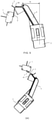
buoy 06 propped against thetrigger bar 04 is provided with a quarter arc surface, and a top end of the arc surface is formed with a sharp corner K. In a normal state, an end portion of thetrigger bar 04 is propped against the arc surface. At this time, if thebuoy 06 floats upward, thebuoy 06 can gently push thetrigger bar 04 to move via the arc surface. However, in the process of transporting the dehumidifier, it is usually necessary to lay the dehumidifier down to lower the center of gravity of the device. At this time, thebuoy 06 can be rotated counterclockwise by a large angle under the action of its own gravity, separating the end portion of thetrigger bar 04 from the arc surface, and propping the sharp corner K at the top end of the arc surface against a side wall of thetrigger bar 04 as shown inFIG. 2b . After the dehumidifier is re-righted, as shown inFIG. 2c , the sharp corner K at the top end of the arc surface is still jammed on the side wall of thetrigger bar 04 and it is difficult for the sharp corner K to return to the normal state. At this time, an alarm will be sent when the dehumidifier is turned on. - In some embodiments, since the first end and the second end are integrated, the second end of the
bracket 4 propped against the elastic piece can be constructed as shown inFIG. 5 , that is, aflange 41 is provided on the second end of thebracket 4 propped against theelastic piece 3, and a contour of theflange 41 is smooth and continuous; theelastic piece 3 will always be propped against theflange 41 when thebracket 4 swings around the rotating axis thereof. Thus, as shown in FIG. 6a, when the dehumidifier is laid down, thebracket 4 is rotated counterclockwise by a large angle, but theelastic piece 3 is still propped against theflange 41. Since the contour of theflange 41 is continuous, after the dehumidifier is re-righted, as shown inFIG. 6b , thebracket 4 can be restored to the normal state under the action of the gravity of thefloat 5. Consequently, the jamming problem is effectively avoided, and the dehumidifier can run normally after being turned on. - In related art shown in FIG. 2a, since the
microswitch 02 is fixed on thesupport frame 01, and the rotating axis of thebuoy 06 is fixed in thewater collection tank 05, if there is a deviation in the relative position between thesupport frame 01 and the water collection tank 05 (e.g., the relative height between thesupport frame 01 and the water collection tank 05), the trigging accuracy of the alarm device will be seriously affected. as shown inFIG. 3 , due to the deviation in the relative height between thesupport frame 01 and thewater collection tank 05 which has existed before thebuoy 06 floats upward, the position of thebuoy 06 is deviated from a position A to a position B, at which time a deviation occurs in a length of the end of thetrigger bar 04 propped against theelastic piece 08 protruding out of thehousing 03, and a deviation also occurs in the relative position between theelastic piece 08 and thebutton 07. As a result, theelastic piece 08 and thebutton 07 cannot be separated after the water is full, thereby causing an alarm error and affecting the trigging accuracy of the alarm device. In addition, when the position of thebuoy 06 is deviated from the position A to the position B, the length of the end of thetrigger bar 04 propped against theelastic piece 08 protruding out of thehousing 03 is rather long, the gap between theelastic piece 08 and thebutton 07 is a negative value, and the reaction force of thetrigger bar 04 on thebuoy 06 is too large. Consequently, it is difficult for thebuoy 06 to float upward under the action of the original small initial buoyancy moment, and a jamming problem occurs. - In some embodiments, as shown in
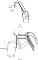
FIG. 5 , theelastic piece 3 can vertically disposed, and when there is a deviation in the height of thebracket 4, theelastic piece 3 will not swing, thereby ensuring the trigging accuracy of the alarm device and improving the ability of the alarm device to resist the interference of deviations. as shown inFIG. 7 , due to the deviation in the relative height between the support frame and the water collection tank which has existed before the buoy floats upward, the position of thebracket 4 is deviated from a position A' to a position B', at which time the position of a contact point between theelastic piece 3 and thebracket 4 moves vertically from a point a to a point b, while the position of theelastic piece 3 remains unchanged, and the relative position between theelastic piece 3 and theswitch button 2 remains unchanged, thereby avoiding an alarm error and ensuring the trigging accuracy of the alarm device. Moreover, when the position of thebracket 4 is deviated from the position A' to the position B', there is no mutual compression between theelastic piece 3 and thebracket 4, and the interaction force therebetween remains unchanged, so that the floating upward of thefloat 5 will not be affected. - It will be noted that, as for the dimensional deviation of the water fullness alarm device, the relative positional deviation between the alarm switch 1 and the rotating axis of the
bracket 4 is mainly considered. The relative positional deviation between the alarm switch 1 and the rotating axis of thebracket 4 includes deviation in the horizontal direction and deviation in the vertical direction. Since a position-limiting structure for ensuring the mounting accuracy in the horizontal direction is usually provided in the dehumidifier, as for the relative positional deviation between the alarm switch 1 and the rotating axis of thebracket 4, the deviation in the vertical direction is mainly considered. - The connection structure between the
bracket 4 and thefloat 5 may be a structure as shown inFIG. 8 , that is, the first end of thebracket 4 connected with thefloat 5 is embedded in the interior of thefloat 5 for fixing. The connection structure between thebracket 4 and thefloat 5 may also be a structure as shown inFIG. 5 , that is, the first end of thebracket 4 connected with thefloat 5 is fixed with afloat mounting box 6, thefloat mounting box 6 is provided with a mountingopening 7, and thefloat 5 can be connected to thefloat mounting box 6 through the mountingopening 7. Compared with the first solution described above, the second solution can effectively fix the relative position of thefloat 5 and thebracket 4 by mounting thefloat 5 in thefloat mounting box 6, so as to prevent thefloat 5 from coming off thebracket 4. - In order to prevent the
float 5 from coming out of the mountingopening 7 by buoyancy, as shown inFIG. 9 , the mountingopening 7 is opened at a lower end of thefloat mounting box 6;The buoyancy direction of thefloat 5 is opposite to the direction in which thefloat 5 comes out of the mountingopening 7 after thefloat 5 is mounted in thefloat mounting box 6. As a result, the buoyancy of thefloat 5 can press thefloat 5 tightly into thefloat mounting box 6 when thefloat 5 floats upward, so as to prevent thefloat 5 from coming off thefloat mounting box 6. On the contrary, if the mountingopening 7 is opened at an upper end of thefloat mounting box 6, the buoyancy direction of thefloat 5 will be the same as the direction in which thefloat 5 comes out of the mountingopening 7, which is advantageous for thefloat 5 to come out of the mountingopening 7 by buoyancy. - As an embodiment of the connection structure between the
float 5 and thefloat mounting box 6, thefloat mounting box 6 is provided with internal threads, an outer wall of thefloat 5 is provided with external threads that can be engaged with the internal threads, and thefloat 5 is connected to thefloat mounting box 6 by the threads. This connection structure has the advantages of good stability and high precision. - As another embodiment of the connection structure between the
float 5 and thefloat mounting box 6, thefloat mounting box 6 is provided with a snap-fit structure, and thefloat 5 can be snapped into thefloat mounting box 6 through the snap-fit structure, therefore thefloat 5 can be mounted in the floating mountingbox 6 in a snap-fit manner. Compared with the threaded connection manner, the snap-fit manner takes less time and is more efficient. - The snap-fit structure may be configured as a fastener, a protrusion, or the like, which is not specifically limited herein. In order to reduce the difficulty in manufacturing the snap-fit structure, as shown in
FIG. 9 , the snap-fit structure may be configured asribs 8 disposed on an inner wall of thefloat mounting box 6, and theribs 8 are in interference fit with a side wall of thefloat 5. This snap-fit structure is simple and easy to implement. - In order to reduce the force used in snapping the
float 5 into thefloat mounting box 6 and reduce the difficulty of using the snap-fit structure, as shown inFIG. 9 , an extending direction of theribs 8 is parallel to a moving direction of thefloat 5 when thefloat 5 is being mounted in thefloat mounting box 6. Therefore, a surface that prevents thefloat 5 from entering thefloat mounting box 6 is a cross section of theribs 8. As the cross-sectional area of theribs 8 is small, thefloat 5 can be pressed into thefloat mounting box 6 with only a small force, and the snap-fit structure is not difficult to use. - In order to improve the reliability of the connection between the
float 5 and thefloat mounting box 6, thefloat mounting box 6 can be constructed as shown inFIG. 9 , that is, afastener 9 is provided on an inner wall of thefloat mounting box 6, and a slot is provided on an outer wall of the float; when thefloat 5 is mounted in thefloat mounting box 6, thefastener 9 can be locked in the slot. Therefore, the relative position between thefloat 5 and thefloat mounting box 6 is fixed through the engagement between thefastener 9 and the slot, and the reliability of the connection between thefloat 5 and thefloat mounting box 6 is improved. - In order to further improve the reliability of the connection between the
float 5 and thefloat mounting box 6, thefloat mounting box 6 can be constructed as shown inFIG. 9 , that is, a plurality offasteners 9 are provided, and the plurality offasteners 9 are evenly arranged along the inner wall of thefloat mounting box 6; a plurality of slots are provided, and the plurality of slots are evenly arranged along the outer wall of thefloat 5; and the plurality offasteners 9 are locked in the plurality of slots in one-to-one correspondence. Therefore, the reliability of the connection between thefloat 5 and thefloat mounting box 6 is further improved through the corresponding engagement between the plurality offasteners 9 and the plurality of slots. - The structure of the
fastener 9 can be as shown inFIG. 10 , that is, thefastener 9 includes afixed end 91 and a snap-inend 92, and the snap-inend 92 of thefastener 9 is located at a side of thefixed end 91 close to the mountingopening 7. Therefore, when thefloat 5 moves toward the mountingopening 7 and is ready to come off thefloat mounting box 6, thefastener 9 will open outwardly under the action of a force, and cannot effectively prevent thefloat 5 from coming off thefloat mounting box 6. In order to avoid the above problem, as shown inFIG. 11 , the snap-inend 92 of thefastener 9 is located on a side of thefixed end 91 away from the mountingopening 7. Therefore, when thefloat 5 moves toward the mountingopening 7 and is ready to come out of thefloat mounting box 6, thefastener 9 will lock thefloat 5 under the action of a moment of force to prevent thefloat 5 from coming out of thefloat mounting box 6, thereby further improving the reliability of the connection between thefloat 5 and thefloat mounting box 6. - In addition, the structure of the
fastener 9 may include a vertical protrusion and a horizontal protrusion as shown inFIG. 9 ; an end of the vertical protrusion is fixed, and another end is free; the horizontal protrusion is fixed to the free end of the vertical protrusion, and the horizontal protrusion is locked in the slot. Thefastener 9 may also be an elastic piece, with one end fixed to the inner wall of thefloat mounting box 6 and another end obliquely disposed. Thefastener 9 may of course be other structures, which is not specifically limited herein. - In related art as shown in FIG. 2a, the buoyancy arm (i.e., L shown in FIG. 2a) is usually less than 20 mm, and the buoyancy moment for driving the
buoy 06 to rotate is small under the action of the buoyancy arm; if a jam occurs between thebuoy 06 and thetrigger bar 04, it will be difficult for the small buoyance moment to drive thebuoy 06 to float upward, thereby disabling the water fullness alarm device. In order to avoid the above problem, as shown inFIG. 5 , the buoyancy arm N (i.e., the horizontal distance between thefloat 5 and the rotating axis of the bracket 4) is greater than 20 mm, which will increase the buoyancy moment for driving thebracket 4 to rotate, thereby avoiding the occurrence of a jam. - In order to determine the buoyancy, the buoyancy should be applied to the
float 5, and it should be avoided to apply the buoyancy to thebracket 4 as much as possible. Therefore, the rotating axis of thebracket 4 is fixed, and the first end of thebracket 4 connected with thefloat 5 is inclined downward. When the liquid level rises, the water first comes into contact with thefloat 5 to generate buoyancy, instead of being in contact with thebracket 4. In this way, the buoyancy is only applied to thefloat 5, which is advantageous for determining the buoyancy. - In order to improve the alarm response accuracy of the water fullness alarm device for a dehumidifier, it is usually required that the alarm switch 1 is not sensitive to the rise of the water level when the
float 5 is at a low water level, and the alarm switch 1 is sensitive to the rise of the water level when thefloat 5 is at a high water level. That is, it is required that the action of thefloat 5 is small at a low water level, and large at a high water level, i.e. when reflected at a release amount of the switch button 2: the release amount of theswitch button 2 is small at a low water level, and the release amount of theswitch button 2 is large at a high water level. For example, at a low water level, the release amount of theswitch button 2 is 0.05 mm when the water level in the water collection tank increases by 1 cm; at a high water level, the release amount of theswitch button 2 is 0.2mm when the water level in the water collection tank increases by 1cm. In this way, not only the alarm response accuracy of the water fullness alarm device for a dehumidifier can be improved, but also the mechanical wear of the water fullness alarm device for a dehumidifier can be reduced. - However, contrary to the above requirement, In related art there is always a problem in the buoyancy for driving the
float 5 to float upward, that is, the rotation is fast at a low water level, and the rotation is slow at a high water level. As shown inFIG. 12 , thefloat 5 floats upward from a position C to a position D, a position E and a position F in order, wherein the floating height of thefloat 5 from the position C to the position D is 1 cm, and the rotation angle of thebracket 4 is 16°; the floating height of thefloat 5 from the position E to the position F is also 1 cm, but the rotation angle of thebracket 4 is reduced to 6.5°. Therefore, in order to reduce the difference between the rotation angle of thefloat 5 at a high water level and the rotation angle of thefloat 5 at a low water level as much as possible, the angle between the first end of thebracket 4 connected with thefloat 5 and the vertical direction when thefloat 5 is in the initial position should be increased. In related art the angle between the first end of thebracket 4 connected with thefloat 5 and the vertical direction is usually less than 11.8°. In order to increase the angle between the first end of thebracket 4 connected with thefloat 5 and the vertical direction, the present invention should make sure that the angle between the first end of thebracket 4 connected with thefloat 5 and the vertical direction is greater than 11.8°, that is, an inclination angle of the first end of thebracket 4 connected with thefloat 5 is less than 78.2°. Exemplarily, as shown inFIG. 13 , curve c shows a relationship between the water level H and the rotation angle θ of thebracket 4 when the initial angle between the first end of thebracket 4 connected with thefloat 5 and the vertical direction is 11.8° In related art. Curve d shows a relationship between the water level H and the rotation angle θ of thebracket 4 when the initial angle between the first end of thebracket 4 connected with thefloat 5 and the vertical direction is 22.4° in the present invention. - As can be seen from
FIG. 13 , compared with the related art, the change relationship between the water level and the rotation angle of thebracket 4 in embodiments of the present invention is more like a linear and uniform change, thereby improving the rotation characteristics of thefloat 5. - In order to make sure that the release amount of the
switch button 2 is small at a low water level and is large at a high water level, so as to improve the alarm response accuracy of the water fullness alarm device for a dehumidifier, a rate of change of a horizontal distance between the rotating axis of thebracket 4 and a contact point between theflange 41 and theelastic piece 3 gradually increases as the rotation angle of thebracket 4 gradually increases. As a result, at a low water level, the second end of thebracket 4 propped against theelastic piece 3 drives theelastic piece 3 to swing around its fixed end to a small extent; at a high water level, the second end of thebracket 4 propped against theelastic piece 3 drives theelastic piece 3 to swing around its fixed end to a large extent. With theelastic piece 3 acting on the switch button, that is, at a low water level, the release amount of theswitch button 2 is small; at a high water level, the release amount of theswitch button 2 is large, thereby improving the alarm response accuracy of the water fullness alarm device for a dehumidifier. Exemplarily, assuming that the horizontal distance between the rotating axis of thebracket 4 and the contact point between theflange 41 and theelastic piece 3 is a first distance,FIG. 14 shows a relationship between a change amount L' of the first distance and the rotation angle θ of thebracket 4. As can be seen fromFIG. 14 , as the rotation angle θ gradually increases, the change amount L' of the first distance gradually increases, and the rate of change of the first distance also gradually increases. - In order to make sure that the release amount of the
switch button 2 is small at a low water level and is high at a high water level, so as to improve the alarm response accuracy of the water fullness alarm device for a dehumidifier, the distance between the fixed end of theelastic piece 3 and the contact point between theflange 41 and theelastic piece 3 gradually decreases when thefloat 5 floats upward. Therefore, according to the principle that the corresponding sides of similar triangles are proportional, as the contact point between theflange 41 and theelastic piece 3 moves closer to the fixed end of theelastic piece 3, the horizontal movement of the contact point per unit distance has a greater influence on the release amount of theswitch button 2. Exemplarily, as shown inFIG. 15 , when the contact point between theflange 41 and theelastic piece 3 moves from a point e to a point f, the distance between the contact point and the fixed end of theelastic piece 3 is reduced. When the contact point between theflange 41 and theelastic piece 3 moves by 1 cm in a horizontal direction of the point e, the release amount of theswitch button 2 is 0.1 mm; when the contact point between theflange 41 and theelastic piece 3 moves by 1 cm in a horizontal direction of the point f, the release amount of theswitch button 2 is 0.2 mm. Exemplarily,FIG. 16 is a relation curve showing a relationship between the change amount L' of the first distance and the release amount / of theswitch button 2. As can be seen fromFIG. 16 , as the change amount L' of the first distance increases, the release amount / of theswitch button 2 gradually increases, and a release rate of theswitch button 2 also gradually increases, thereby making sure that the release amount of theswitch button 2 is small at a low water level and is large at a high water level. Therefore, the alarm response accuracy of the water fullness alarm device for a dehumidifier is improved. - In summary, the alarm response accuracy of the water fullness alarm device for a dehumidifier can be improved by the following two features:
- the first feature: as a rotation angle of the
bracket 4 gradually increases, a rate of change of a horizontal distance between the rotating axis of thebracket 4 and a contact point between theflange 41 and theelastic piece 3 gradually increases; - the second feature: when the
float 5 floats upward, a distance between a fixed end of theelastic piece 3 and a contact point between theflange 41 and theelastic piece 3 gradually decreases. - The water fullness alarm device for a dehumidifier provided by embodiments of the present invention may have one of the two features above, and may have the two features at the same time, which is not specifically limited herein. Exemplarily, in the case where the water fullness alarm device for a dehumidifier provided by embodiments of the present invention have the two features at the same time, that is,
FIG. 14 andFIG. 16 are superimposed to obtainFIG. 17 . Compared with the curve shown inFIG. 14 and the curve shown inFIG. 16 , in the obtainedFIG. 17 , the release amount of theswitch button 2 is larger at a high water level. Correspondingly, the sensitivity is higher, and the alarm response accuracy is higher. Therefore, even if the curve d shown inFIG. 13 is further superimposed on the superimposed curve as shown inFig. 17 , in the obtained curve as shown inFIG. 18 , the requirement that the release amount of theswitch button 2 is small at a low water level and is large at a high water level will still be met. - In related art shown in FIG. 2a, the
buoy 06 has a barrel structure. As shown inFIG. 4 , an upper end of the barrel structure is closed, and a lower end is open. When a bottom of thebuoy 06 and a liquid level of thewater collection tank 05 are in contact, thebuoy 06 generates buoyancy by the air stored therein. Due to the small cross-sectional area of thebuoy 06, the buoyancy generated by thebuoy 06 is small; and due to the vibration of the whole machine, the air inside thebuoy 06 may be discharged as bubbles, causing the buoyance generated by thebuoy 06 to be unstable. In order to avoid the above problem, as shown inFIG. 5 ,thefloat 5 is made of a foam material. Compared with the prior art, in which the buoyancy is generated by air, the present invention uses the foam material to generate buoyancy, so that the buoyancy generated is relatively larger and more stable. - In the description of this invention, specific features, structures, materials or characteristics may be combined in any suitable manner in any one or more embodiments or examples.
Claims (13)
- A water fullness alarm device for a dehumidifier, comprising an alarm switch (1), and a float (5), wherein,the alarm switch (1) comprises a switch button (2) covered with an elastic piece (3); one end of the elastic piece (3) is fixed to the alarm switch (1), and another end is free;the water fullness alarm device further comprises a bracket (4), and the bracket (4) is rotatable; a first end of the bracket (4) is connected with the float (5), and a second end of the bracket (4) comprises a flange (41) which is propped against the elastic piece (3);when the float (5) floats upward, the second end of the bracket (4) propped against the elastic piece (3) can swing around a rotating axis of the bracket (4) and drive the elastic piece (3) to trigger the switch button (2);wherein a contour of the flange (41) is smooth and continuous; when the bracket (4) swings around the rotating axis thereof, the elastic piece (3) will always be propped against the flange (41);characterized in thatas a rotation angle of the bracket (4) gradually increases, a rate of change of a horizontal distance between the rotating axis of the bracket (4) and a contact point between the flange (41) and the elastic piece (3) gradually increases.
- The water fullness alarm device for a dehumidifier according to claim 1, wherein the elastic piece (3) is substantially vertically disposed.
- The water fullness alarm device for a dehumidifier according to claim 1, wherein the first end of the bracket (4) connected with the float (5) is provided with a float mounting box (6), the float mounting box (6) is provided with a mounting opening (7), and the float (5) can be connected to the float mounting box (6) through the mounting opening (7).
- The water fullness alarm device for a dehumidifier according to claim 3, wherein the float mounting box (6) is provided with a snap-fit structure, and the float (5) can be snapped into the float mounting box (6) via the snap-fit structure.
- The water fullness alarm device for a dehumidifier according to claim 4, wherein the snap-fit structure is configured as ribs (8) disposed on an inner wall of the float mounting box (6), and the ribs (8) are in interference fit with a side wall of the float (5).
- The water fullness alarm device for a dehumidifier according to claim 3, wherein an inner wall of the float mounting box (6) is provided with a fastener (9), and an outer wall of the float (5) is provided with a slot; when the float (5) is mounted in the float mounting box (6), the fastener (9) is able to locked in the slot.
- The water fullness alarm device for a dehumidifier according to claim 6, wherein a plurality of fasteners (9) are provided, and the plurality of fasteners (9) are evenly arranged along the inner wall of the float mounting box (6); a plurality of slots are provided, and the plurality of slots are evenly arranged along the outer wall of the float (5); and the plurality of fasteners (9) are locked in the plurality of slots in one-to-one correspondence.
- The water fullness alarm device for a dehumidifier according to claim 6 or 7, wherein the fastener (9) comprises a fixed end (91) and a snap-in end (92), and the snap-in end (92) of the fastener (9) is located at a side of the fixed end away from the mounting opening (7).
- The water fullness alarm device for a dehumidifier according to claim 1, wherein a horizontal distance between the float (5) and the rotating axis of the bracket (4) is greater than 20 mm.
- The water fullness alarm device for a dehumidifier according to claim 1, wherein the rotating axis of the bracket (4) is fixed in a water collection tank of the dehumidifier, and the first end of the bracket (4) connected with the float (5) is inclined downward.
- The water fullness alarm device for a dehumidifier according to claim 10, wherein an inclination angle of the first end of the bracket (4) connected with the float (5) is less than 78.2°.
- The water fullness alarm device for a dehumidifier according to claim 1, wherein when the float (5) floats upward, a distance between a fixed end of the elastic piece (3) and a contact point between the flange (41) and the elastic piece (3) gradually decreases, wherein the fixed end of the elastic piece (3) is fixed to the alarm switch (1).
- The water fullness alarm device for a dehumidifier according to claim 1, wherein both the first end and the second end of the bracket (4) swing around the rotating axis of the bracket (4) synchronously.
Applications Claiming Priority (2)
| Application Number | Priority Date | Filing Date | Title |
|---|---|---|---|
| CN201610181914.1A CN105784072B (en) | 2016-03-28 | 2016-03-28 | Dehumidifier is with full alarm device of water |
| PCT/CN2016/083736 WO2017166414A1 (en) | 2016-03-28 | 2016-05-27 | Water fullness alarm device for dehumidifier |
Publications (3)
| Publication Number | Publication Date |
|---|---|
| EP3439010A1 EP3439010A1 (en) | 2019-02-06 |
| EP3439010A4 EP3439010A4 (en) | 2019-10-30 |
| EP3439010B1 true EP3439010B1 (en) | 2022-02-23 |
Family
ID=56391985
Family Applications (1)
| Application Number | Title | Priority Date | Filing Date |
|---|---|---|---|
| EP16896188.6A Active EP3439010B1 (en) | 2016-03-28 | 2016-05-27 | Water fullness alarm device for dehumidifier |
Country Status (5)
| Country | Link |
|---|---|
| US (1) | US10852176B2 (en) |
| EP (1) | EP3439010B1 (en) |
| CN (1) | CN105784072B (en) |
| ES (1) | ES2907709T3 (en) |
| WO (1) | WO2017166414A1 (en) |
Families Citing this family (5)
| Publication number | Priority date | Publication date | Assignee | Title |
|---|---|---|---|---|
| US20190378670A1 (en) * | 2018-06-08 | 2019-12-12 | Pityu Controls Inc. | Adjustable add-on apparatuses for a switch and associated methods |
| CN108855797A (en) * | 2018-09-12 | 2018-11-23 | 珠海格力电工有限公司 | Liquid storage tank and enameled wire coating device |
| CN114683411A (en) * | 2020-12-30 | 2022-07-01 | 三一汽车制造有限公司 | Material level detection device, mixer truck and cooperative operation method |
| CN113514132A (en) * | 2021-04-21 | 2021-10-19 | 四川华能宝兴河水电有限责任公司 | Intelligent water level detection device for hydropower station |
| DE102022102535B4 (en) * | 2022-02-03 | 2026-05-21 | Bayerische Motoren Werke Aktiengesellschaft | Method and device for detecting an impairment of a lever actuator |
Citations (1)
| Publication number | Priority date | Publication date | Assignee | Title |
|---|---|---|---|---|
| US4742691A (en) * | 1986-06-02 | 1988-05-10 | White Consolidated Industries, Inc. | Dehumidifier |
Family Cites Families (44)
| Publication number | Priority date | Publication date | Assignee | Title |
|---|---|---|---|---|
| US1620823A (en) * | 1925-07-08 | 1927-03-15 | William Liston | Liquid-level indicator |
| US1725208A (en) * | 1928-01-21 | 1929-08-20 | Charles E Potter | Gravity-tank float device |
| US2672535A (en) * | 1952-06-17 | 1954-03-16 | Robert B Macdonald | Warning signal for fluid brakes |
| US2867993A (en) * | 1954-02-01 | 1959-01-13 | Admiral Corp | Dehumidifier |
| US2725196A (en) * | 1954-06-07 | 1955-11-29 | Gen Motors Corp | Dehumidifier control system |
| US2897853A (en) * | 1957-11-12 | 1959-08-04 | Roland W Anstine | Filling indicator for underground tanks |
| US3110161A (en) * | 1962-04-04 | 1963-11-12 | Admiral Corp | Float switch assembly for air conditioning apparatus |
| US3686451A (en) * | 1971-02-01 | 1972-08-22 | John E Pottharst Jr | Liquid level control assembly |
| US4050102A (en) * | 1976-03-05 | 1977-09-27 | Monogram Industries, Inc. | Recirculating toilet system |
| US4181021A (en) * | 1978-07-28 | 1980-01-01 | Combustion Engineering, Inc. | Position transmitter |
| US4428207A (en) * | 1981-10-09 | 1984-01-31 | Martin Industries, Inc. | Dehumidifier |
| US4475359A (en) * | 1981-10-27 | 1984-10-09 | Tokyo Shibaura Denki Kabushiki Kaisha | Air conditioning apparatus |
| US4587923A (en) * | 1983-08-12 | 1986-05-13 | Santiago Mejia | Battery cap indicator |
| US4635480A (en) * | 1984-10-15 | 1987-01-13 | Rochester Gauges, Inc. | Density compensating float |
| US4712382A (en) * | 1986-10-20 | 1987-12-15 | Whirlpool Corporation | Dehumidifier having low profile receptacle |
| JP2550209B2 (en) * | 1989-10-25 | 1996-11-06 | 株式会社日立製作所 | Buoyancy type liquid level detector |
| US5072618A (en) * | 1990-09-21 | 1991-12-17 | Rochester Gauges, Inc. | Adjustable LPG gauge |
| US5294917A (en) * | 1992-04-06 | 1994-03-15 | Wilkins Larry C | Liquid level sensor using float and magnetic means |
| US5365969A (en) * | 1994-01-21 | 1994-11-22 | White Consolidated Industries, Inc. | Float with skirt to prevent leakage due to oversudsing |
| CN2204406Y (en) * | 1994-10-21 | 1995-08-02 | 北京比特实业股份有限公司 | Moisture-removing device for cabinet and cupboard etc. |
| US5850175A (en) * | 1997-02-19 | 1998-12-15 | Yeilding; Hollis | Water level detector |
| US6089086A (en) * | 1997-08-26 | 2000-07-18 | Rochester Gauges, Inc. | Liquid level gauge |
| US5884495A (en) * | 1997-10-09 | 1999-03-23 | Whirlpool Corporation | Dehumidifier with an adjustable float for setting the moisture level shut off |
| JP3969820B2 (en) * | 1998-01-27 | 2007-09-05 | 三菱重工業株式会社 | Fuel gauge device for fuel tank |
| US6253609B1 (en) * | 1998-08-28 | 2001-07-03 | Rochester Gauges, Inc. | Liquid level gauge with hinged float arm |
| US6216534B1 (en) * | 1998-08-28 | 2001-04-17 | Rochester Gauges, Inc. | Liquid level gauge with hinged float arm |
| US6375430B1 (en) * | 2000-05-03 | 2002-04-23 | Campbell Hausfeld/Scott Fetzer Company | Sump pump alarm |
| US6415618B1 (en) * | 2000-08-30 | 2002-07-09 | Lg Electronics Inc. | Device for detecting full dehumidifier water tank |
| KR20040021350A (en) * | 2002-09-03 | 2004-03-10 | 엘지전자 주식회사 | A float of dehumidifier |
| US7067749B1 (en) * | 2004-09-02 | 2006-06-27 | Christopher Ralph Cantolino | Float switch and mounting system assembly |
| US7067750B1 (en) * | 2004-09-02 | 2006-06-27 | Christopher Ralph Cantolino | Float switch and mounting system assembly |
| US7710283B1 (en) * | 2008-01-31 | 2010-05-04 | Christopher Ralph Cantolino | Fluid-level sensing device with encapsulated micro switch |
| US7967267B1 (en) * | 2008-01-31 | 2011-06-28 | Christopher Ralph Cantolino | Clamping assembly with integral rail plate |
| US7802587B1 (en) * | 2008-02-26 | 2010-09-28 | Ball Ralph A | Float valve and method |
| US7895849B2 (en) * | 2008-07-03 | 2011-03-01 | New Widetech Industries Co., Ltd. | Dehumidifier with multistage draining |
| CN201373512Y (en) * | 2008-12-30 | 2009-12-30 | 广东美的电器股份有限公司 | An air-conditioning device with full water protection function |
| CN201374282Y (en) * | 2008-12-30 | 2009-12-30 | 广东美的电器股份有限公司 | Micro switch and water full protection device with the micro switch |
| CN201373528Y (en) * | 2008-12-30 | 2009-12-30 | 广东美的电器股份有限公司 | A water full protection device for a water tank |
| CN201348974Y (en) * | 2008-12-30 | 2009-11-18 | 广东美的电器股份有限公司 | Novel micro-active switch structure |
| US8701701B2 (en) * | 2012-09-25 | 2014-04-22 | Chin-Cheng Huang | Float switch of a humidifier |
| US9249981B2 (en) * | 2013-09-27 | 2016-02-02 | Diversitech Corporation | Condensate overflow detection device |
| US9188992B2 (en) * | 2013-10-02 | 2015-11-17 | New Widetech Industries Co., Ltd. | Water tank limit switch assembly |
| CN204084737U (en) * | 2014-08-28 | 2015-01-07 | Tcl空调器(中山)有限公司 | dehumidifier and float assembly thereof |
| US10539441B2 (en) * | 2017-05-31 | 2020-01-21 | Thomas Products Ltd. | Flow or level sensor/switch system |
-
2016
- 2016-03-28 CN CN201610181914.1A patent/CN105784072B/en active Active
- 2016-05-27 EP EP16896188.6A patent/EP3439010B1/en active Active
- 2016-05-27 WO PCT/CN2016/083736 patent/WO2017166414A1/en not_active Ceased
- 2016-05-27 ES ES16896188T patent/ES2907709T3/en active Active
-
2018
- 2018-09-27 US US16/144,647 patent/US10852176B2/en active Active
Patent Citations (1)
| Publication number | Priority date | Publication date | Assignee | Title |
|---|---|---|---|---|
| US4742691A (en) * | 1986-06-02 | 1988-05-10 | White Consolidated Industries, Inc. | Dehumidifier |
Also Published As
| Publication number | Publication date |
|---|---|
| US20190101432A1 (en) | 2019-04-04 |
| ES2907709T3 (en) | 2022-04-26 |
| US10852176B2 (en) | 2020-12-01 |
| WO2017166414A1 (en) | 2017-10-05 |
| EP3439010A4 (en) | 2019-10-30 |
| CN105784072B (en) | 2018-10-19 |
| CN105784072A (en) | 2016-07-20 |
| EP3439010A1 (en) | 2019-02-06 |
Similar Documents
| Publication | Publication Date | Title |
|---|---|---|
| US10852176B2 (en) | Water fullness alarm device and a dehumidifier | |
| US9720549B2 (en) | Touch-sensitive display device | |
| US5250927A (en) | Inside mounting door stop and alarm | |
| JP2004264193A (en) | Water level detector | |
| CN201373528Y (en) | A water full protection device for a water tank | |
| US4326196A (en) | Universal gravity operated intrusion sensing device | |
| KR101185401B1 (en) | Open and close sensing device | |
| TWI595524B (en) | Paddle switch level indicator and driving mechanism thereof | |
| JP5194697B2 (en) | Water level detector | |
| US20130322960A1 (en) | Locking assembly | |
| JP5053248B2 (en) | Electrical equipment | |
| CN115727745A (en) | Mask box opening detection device and mask box | |
| CN201348974Y (en) | Novel micro-active switch structure | |
| CN111314522A (en) | Electronic equipment | |
| CN112568848B (en) | Overflow switch and dish washer | |
| CN103032939B (en) | Dehumidifier | |
| CN201732162U (en) | Optical navigation device and sensor cover plate thereof | |
| CN223180415U (en) | earthquake sensors | |
| CN222165017U (en) | Float assembly, water tank and dehumidifier | |
| JP5338892B2 (en) | Game machine | |
| JP2009059907A (en) | Waterproof case | |
| CN209446788U (en) | A kind of Anti-error structure of mediate contact | |
| JP3378047B2 (en) | Paper roll holder | |
| KR100937770B1 (en) | Locking device having improved locking function | |
| JP2017082410A (en) | Lock device |
Legal Events
| Date | Code | Title | Description |
|---|---|---|---|
| STAA | Information on the status of an ep patent application or granted ep patent |
Free format text: STATUS: THE INTERNATIONAL PUBLICATION HAS BEEN MADE |
|
| PUAI | Public reference made under article 153(3) epc to a published international application that has entered the european phase |
Free format text: ORIGINAL CODE: 0009012 |
|
| STAA | Information on the status of an ep patent application or granted ep patent |
Free format text: STATUS: REQUEST FOR EXAMINATION WAS MADE |
|
| 17P | Request for examination filed |
Effective date: 20181002 |
|
| AK | Designated contracting states |
Kind code of ref document: A1 Designated state(s): AL AT BE BG CH CY CZ DE DK EE ES FI FR GB GR HR HU IE IS IT LI LT LU LV MC MK MT NL NO PL PT RO RS SE SI SK SM TR |
|
| AX | Request for extension of the european patent |
Extension state: BA ME |
|
| RAP1 | Party data changed (applicant data changed or rights of an application transferred) |
Owner name: HISENSE HOME APPLIANCES GROUP CO., LTD. Owner name: HISENSE (GUANGDONG) AIR CONDITIONER CO., LTD. |
|
| DAV | Request for validation of the european patent (deleted) | ||
| DAX | Request for extension of the european patent (deleted) | ||
| A4 | Supplementary search report drawn up and despatched |
Effective date: 20190927 |
|
| RIC1 | Information provided on ipc code assigned before grant |
Ipc: H01H 35/18 20060101AFI20190923BHEP Ipc: F24F 3/14 20060101ALI20190923BHEP |
|
| RAP1 | Party data changed (applicant data changed or rights of an application transferred) |
Owner name: HISENSE HOME APPLIANCES GROUP CO., LTD. Owner name: HISENSE (GUANGDONG) AIR CONDITIONER CO., LTD. |
|
| STAA | Information on the status of an ep patent application or granted ep patent |
Free format text: STATUS: EXAMINATION IS IN PROGRESS |
|
| 17Q | First examination report despatched |
Effective date: 20210326 |
|
| GRAP | Despatch of communication of intention to grant a patent |
Free format text: ORIGINAL CODE: EPIDOSNIGR1 |
|
| STAA | Information on the status of an ep patent application or granted ep patent |
Free format text: STATUS: GRANT OF PATENT IS INTENDED |
|
| GRAJ | Information related to disapproval of communication of intention to grant by the applicant or resumption of examination proceedings by the epo deleted |
Free format text: ORIGINAL CODE: EPIDOSDIGR1 |
|
| GRAP | Despatch of communication of intention to grant a patent |
Free format text: ORIGINAL CODE: EPIDOSNIGR1 |
|
| INTG | Intention to grant announced |
Effective date: 20211013 |
|
| INTG | Intention to grant announced |
Effective date: 20211027 |
|
| GRAS | Grant fee paid |
Free format text: ORIGINAL CODE: EPIDOSNIGR3 |
|
| GRAA | (expected) grant |
Free format text: ORIGINAL CODE: 0009210 |
|
| STAA | Information on the status of an ep patent application or granted ep patent |
Free format text: STATUS: THE PATENT HAS BEEN GRANTED |
|
| AK | Designated contracting states |
Kind code of ref document: B1 Designated state(s): AL AT BE BG CH CY CZ DE DK EE ES FI FR GB GR HR HU IE IS IT LI LT LU LV MC MK MT NL NO PL PT RO RS SE SI SK SM TR |
|
| REG | Reference to a national code |
Ref country code: GB Ref legal event code: FG4D |
|
| REG | Reference to a national code |
Ref country code: CH Ref legal event code: EP |
|
| REG | Reference to a national code |
Ref country code: AT Ref legal event code: REF Ref document number: 1471091 Country of ref document: AT Kind code of ref document: T Effective date: 20220315 |
|
| REG | Reference to a national code |
Ref country code: IE Ref legal event code: FG4D |
|
| REG | Reference to a national code |
Ref country code: DE Ref legal event code: R096 Ref document number: 602016069472 Country of ref document: DE |
|
| REG | Reference to a national code |
Ref country code: ES Ref legal event code: FG2A Ref document number: 2907709 Country of ref document: ES Kind code of ref document: T3 Effective date: 20220426 |
|
| REG | Reference to a national code |
Ref country code: LT Ref legal event code: MG9D |
|
| REG | Reference to a national code |
Ref country code: NL Ref legal event code: MP Effective date: 20220223 |
|
| REG | Reference to a national code |
Ref country code: AT Ref legal event code: MK05 Ref document number: 1471091 Country of ref document: AT Kind code of ref document: T Effective date: 20220223 |
|
| PG25 | Lapsed in a contracting state [announced via postgrant information from national office to epo] |
Ref country code: SE Free format text: LAPSE BECAUSE OF FAILURE TO SUBMIT A TRANSLATION OF THE DESCRIPTION OR TO PAY THE FEE WITHIN THE PRESCRIBED TIME-LIMIT Effective date: 20220223 Ref country code: RS Free format text: LAPSE BECAUSE OF FAILURE TO SUBMIT A TRANSLATION OF THE DESCRIPTION OR TO PAY THE FEE WITHIN THE PRESCRIBED TIME-LIMIT Effective date: 20220223 Ref country code: PT Free format text: LAPSE BECAUSE OF FAILURE TO SUBMIT A TRANSLATION OF THE DESCRIPTION OR TO PAY THE FEE WITHIN THE PRESCRIBED TIME-LIMIT Effective date: 20220623 Ref country code: NO Free format text: LAPSE BECAUSE OF FAILURE TO SUBMIT A TRANSLATION OF THE DESCRIPTION OR TO PAY THE FEE WITHIN THE PRESCRIBED TIME-LIMIT Effective date: 20220523 Ref country code: NL Free format text: LAPSE BECAUSE OF FAILURE TO SUBMIT A TRANSLATION OF THE DESCRIPTION OR TO PAY THE FEE WITHIN THE PRESCRIBED TIME-LIMIT Effective date: 20220223 Ref country code: LT Free format text: LAPSE BECAUSE OF FAILURE TO SUBMIT A TRANSLATION OF THE DESCRIPTION OR TO PAY THE FEE WITHIN THE PRESCRIBED TIME-LIMIT Effective date: 20220223 Ref country code: HR Free format text: LAPSE BECAUSE OF FAILURE TO SUBMIT A TRANSLATION OF THE DESCRIPTION OR TO PAY THE FEE WITHIN THE PRESCRIBED TIME-LIMIT Effective date: 20220223 Ref country code: BG Free format text: LAPSE BECAUSE OF FAILURE TO SUBMIT A TRANSLATION OF THE DESCRIPTION OR TO PAY THE FEE WITHIN THE PRESCRIBED TIME-LIMIT Effective date: 20220523 |
|
| PG25 | Lapsed in a contracting state [announced via postgrant information from national office to epo] |
Ref country code: PL Free format text: LAPSE BECAUSE OF FAILURE TO SUBMIT A TRANSLATION OF THE DESCRIPTION OR TO PAY THE FEE WITHIN THE PRESCRIBED TIME-LIMIT Effective date: 20220223 Ref country code: LV Free format text: LAPSE BECAUSE OF FAILURE TO SUBMIT A TRANSLATION OF THE DESCRIPTION OR TO PAY THE FEE WITHIN THE PRESCRIBED TIME-LIMIT Effective date: 20220223 Ref country code: GR Free format text: LAPSE BECAUSE OF FAILURE TO SUBMIT A TRANSLATION OF THE DESCRIPTION OR TO PAY THE FEE WITHIN THE PRESCRIBED TIME-LIMIT Effective date: 20220524 Ref country code: FI Free format text: LAPSE BECAUSE OF FAILURE TO SUBMIT A TRANSLATION OF THE DESCRIPTION OR TO PAY THE FEE WITHIN THE PRESCRIBED TIME-LIMIT Effective date: 20220223 Ref country code: AT Free format text: LAPSE BECAUSE OF FAILURE TO SUBMIT A TRANSLATION OF THE DESCRIPTION OR TO PAY THE FEE WITHIN THE PRESCRIBED TIME-LIMIT Effective date: 20220223 |
|
| PG25 | Lapsed in a contracting state [announced via postgrant information from national office to epo] |
Ref country code: IS Free format text: LAPSE BECAUSE OF FAILURE TO SUBMIT A TRANSLATION OF THE DESCRIPTION OR TO PAY THE FEE WITHIN THE PRESCRIBED TIME-LIMIT Effective date: 20220623 |
|
| PG25 | Lapsed in a contracting state [announced via postgrant information from national office to epo] |
Ref country code: SM Free format text: LAPSE BECAUSE OF FAILURE TO SUBMIT A TRANSLATION OF THE DESCRIPTION OR TO PAY THE FEE WITHIN THE PRESCRIBED TIME-LIMIT Effective date: 20220223 Ref country code: SK Free format text: LAPSE BECAUSE OF FAILURE TO SUBMIT A TRANSLATION OF THE DESCRIPTION OR TO PAY THE FEE WITHIN THE PRESCRIBED TIME-LIMIT Effective date: 20220223 Ref country code: RO Free format text: LAPSE BECAUSE OF FAILURE TO SUBMIT A TRANSLATION OF THE DESCRIPTION OR TO PAY THE FEE WITHIN THE PRESCRIBED TIME-LIMIT Effective date: 20220223 Ref country code: EE Free format text: LAPSE BECAUSE OF FAILURE TO SUBMIT A TRANSLATION OF THE DESCRIPTION OR TO PAY THE FEE WITHIN THE PRESCRIBED TIME-LIMIT Effective date: 20220223 Ref country code: DK Free format text: LAPSE BECAUSE OF FAILURE TO SUBMIT A TRANSLATION OF THE DESCRIPTION OR TO PAY THE FEE WITHIN THE PRESCRIBED TIME-LIMIT Effective date: 20220223 Ref country code: CZ Free format text: LAPSE BECAUSE OF FAILURE TO SUBMIT A TRANSLATION OF THE DESCRIPTION OR TO PAY THE FEE WITHIN THE PRESCRIBED TIME-LIMIT Effective date: 20220223 |
|
| REG | Reference to a national code |
Ref country code: DE Ref legal event code: R097 Ref document number: 602016069472 Country of ref document: DE |
|
| PG25 | Lapsed in a contracting state [announced via postgrant information from national office to epo] |
Ref country code: AL Free format text: LAPSE BECAUSE OF FAILURE TO SUBMIT A TRANSLATION OF THE DESCRIPTION OR TO PAY THE FEE WITHIN THE PRESCRIBED TIME-LIMIT Effective date: 20220223 |
|
| REG | Reference to a national code |
Ref country code: DE Ref legal event code: R119 Ref document number: 602016069472 Country of ref document: DE |
|
| PLBE | No opposition filed within time limit |
Free format text: ORIGINAL CODE: 0009261 |
|
| REG | Reference to a national code |
Ref country code: CH Ref legal event code: PL |
|
| STAA | Information on the status of an ep patent application or granted ep patent |
Free format text: STATUS: NO OPPOSITION FILED WITHIN TIME LIMIT |
|
| REG | Reference to a national code |
Ref country code: BE Ref legal event code: MM Effective date: 20220531 |
|
| GBPC | Gb: european patent ceased through non-payment of renewal fee |
Effective date: 20220527 |
|
| PG25 | Lapsed in a contracting state [announced via postgrant information from national office to epo] |
Ref country code: MC Free format text: LAPSE BECAUSE OF FAILURE TO SUBMIT A TRANSLATION OF THE DESCRIPTION OR TO PAY THE FEE WITHIN THE PRESCRIBED TIME-LIMIT Effective date: 20220223 Ref country code: LU Free format text: LAPSE BECAUSE OF NON-PAYMENT OF DUE FEES Effective date: 20220527 Ref country code: LI Free format text: LAPSE BECAUSE OF NON-PAYMENT OF DUE FEES Effective date: 20220531 Ref country code: CH Free format text: LAPSE BECAUSE OF NON-PAYMENT OF DUE FEES Effective date: 20220531 |
|
| 26N | No opposition filed |
Effective date: 20221124 |
|
| PG25 | Lapsed in a contracting state [announced via postgrant information from national office to epo] |
Ref country code: SI Free format text: LAPSE BECAUSE OF FAILURE TO SUBMIT A TRANSLATION OF THE DESCRIPTION OR TO PAY THE FEE WITHIN THE PRESCRIBED TIME-LIMIT Effective date: 20220223 |
|
| PG25 | Lapsed in a contracting state [announced via postgrant information from national office to epo] |
Ref country code: IE Free format text: LAPSE BECAUSE OF NON-PAYMENT OF DUE FEES Effective date: 20220527 Ref country code: FR Free format text: LAPSE BECAUSE OF NON-PAYMENT OF DUE FEES Effective date: 20220531 |
|
| PG25 | Lapsed in a contracting state [announced via postgrant information from national office to epo] |
Ref country code: GB Free format text: LAPSE BECAUSE OF NON-PAYMENT OF DUE FEES Effective date: 20220527 Ref country code: DE Free format text: LAPSE BECAUSE OF NON-PAYMENT OF DUE FEES Effective date: 20221201 Ref country code: BE Free format text: LAPSE BECAUSE OF NON-PAYMENT OF DUE FEES Effective date: 20220531 |
|
| P01 | Opt-out of the competence of the unified patent court (upc) registered |
Effective date: 20230511 |
|
| PG25 | Lapsed in a contracting state [announced via postgrant information from national office to epo] |
Ref country code: HU Free format text: LAPSE BECAUSE OF FAILURE TO SUBMIT A TRANSLATION OF THE DESCRIPTION OR TO PAY THE FEE WITHIN THE PRESCRIBED TIME-LIMIT; INVALID AB INITIO Effective date: 20160527 |
|
| PG25 | Lapsed in a contracting state [announced via postgrant information from national office to epo] |
Ref country code: MK Free format text: LAPSE BECAUSE OF FAILURE TO SUBMIT A TRANSLATION OF THE DESCRIPTION OR TO PAY THE FEE WITHIN THE PRESCRIBED TIME-LIMIT Effective date: 20220223 Ref country code: CY Free format text: LAPSE BECAUSE OF FAILURE TO SUBMIT A TRANSLATION OF THE DESCRIPTION OR TO PAY THE FEE WITHIN THE PRESCRIBED TIME-LIMIT Effective date: 20220223 |
|
| PG25 | Lapsed in a contracting state [announced via postgrant information from national office to epo] |
Ref country code: MT Free format text: LAPSE BECAUSE OF FAILURE TO SUBMIT A TRANSLATION OF THE DESCRIPTION OR TO PAY THE FEE WITHIN THE PRESCRIBED TIME-LIMIT Effective date: 20220223 |
|
| PGFP | Annual fee paid to national office [announced via postgrant information from national office to epo] |
Ref country code: IT Payment date: 20250527 Year of fee payment: 10 |
|
| PGFP | Annual fee paid to national office [announced via postgrant information from national office to epo] |
Ref country code: ES Payment date: 20250630 Year of fee payment: 10 |
|
| PG25 | Lapsed in a contracting state [announced via postgrant information from national office to epo] |
Ref country code: TR Free format text: LAPSE BECAUSE OF FAILURE TO SUBMIT A TRANSLATION OF THE DESCRIPTION OR TO PAY THE FEE WITHIN THE PRESCRIBED TIME-LIMIT Effective date: 20220223 |