EP3438878A1 - Iris image acquisition method, mobile terminal and storage medium - Google Patents
Iris image acquisition method, mobile terminal and storage medium Download PDFInfo
- Publication number
- EP3438878A1 EP3438878A1 EP18183847.5A EP18183847A EP3438878A1 EP 3438878 A1 EP3438878 A1 EP 3438878A1 EP 18183847 A EP18183847 A EP 18183847A EP 3438878 A1 EP3438878 A1 EP 3438878A1
- Authority
- EP
- European Patent Office
- Prior art keywords
- working mode
- acquisition device
- infrared
- supplementary
- infrared light
- Prior art date
- Legal status (The legal status is an assumption and is not a legal conclusion. Google has not performed a legal analysis and makes no representation as to the accuracy of the status listed.)
- Granted
Links
Images


Classifications
-
- G—PHYSICS
- G06—COMPUTING OR CALCULATING; COUNTING
- G06V—IMAGE OR VIDEO RECOGNITION OR UNDERSTANDING
- G06V40/00—Recognition of biometric, human-related or animal-related patterns in image or video data
- G06V40/10—Human or animal bodies, e.g. vehicle occupants or pedestrians; Body parts, e.g. hands
- G06V40/18—Eye characteristics, e.g. of the iris
- G06V40/19—Sensors therefor
-
- G—PHYSICS
- G06—COMPUTING OR CALCULATING; COUNTING
- G06V—IMAGE OR VIDEO RECOGNITION OR UNDERSTANDING
- G06V10/00—Arrangements for image or video recognition or understanding
- G06V10/10—Image acquisition
- G06V10/12—Details of acquisition arrangements; Constructional details thereof
- G06V10/14—Optical characteristics of the device performing the acquisition or on the illumination arrangements
- G06V10/141—Control of illumination
-
- G—PHYSICS
- G06—COMPUTING OR CALCULATING; COUNTING
- G06V—IMAGE OR VIDEO RECOGNITION OR UNDERSTANDING
- G06V10/00—Arrangements for image or video recognition or understanding
- G06V10/10—Image acquisition
- G06V10/12—Details of acquisition arrangements; Constructional details thereof
- G06V10/14—Optical characteristics of the device performing the acquisition or on the illumination arrangements
- G06V10/143—Sensing or illuminating at different wavelengths
-
- G—PHYSICS
- G06—COMPUTING OR CALCULATING; COUNTING
- G06V—IMAGE OR VIDEO RECOGNITION OR UNDERSTANDING
- G06V10/00—Arrangements for image or video recognition or understanding
- G06V10/10—Image acquisition
- G06V10/12—Details of acquisition arrangements; Constructional details thereof
- G06V10/14—Optical characteristics of the device performing the acquisition or on the illumination arrangements
- G06V10/147—Details of sensors, e.g. sensor lenses
-
- G—PHYSICS
- G06—COMPUTING OR CALCULATING; COUNTING
- G06V—IMAGE OR VIDEO RECOGNITION OR UNDERSTANDING
- G06V40/00—Recognition of biometric, human-related or animal-related patterns in image or video data
- G06V40/10—Human or animal bodies, e.g. vehicle occupants or pedestrians; Body parts, e.g. hands
- G06V40/18—Eye characteristics, e.g. of the iris
- G06V40/193—Preprocessing; Feature extraction
-
- G—PHYSICS
- G09—EDUCATION; CRYPTOGRAPHY; DISPLAY; ADVERTISING; SEALS
- G09G—ARRANGEMENTS OR CIRCUITS FOR CONTROL OF INDICATING DEVICES USING STATIC MEANS TO PRESENT VARIABLE INFORMATION
- G09G3/00—Control arrangements or circuits, of interest only in connection with visual indicators other than cathode-ray tubes
- G09G3/20—Control arrangements or circuits, of interest only in connection with visual indicators other than cathode-ray tubes for presentation of an assembly of a number of characters, e.g. a page, by composing the assembly by combination of individual elements arranged in a matrix no fixed position being assigned to or needed to be assigned to the individual characters or partial characters
- G09G3/34—Control arrangements or circuits, of interest only in connection with visual indicators other than cathode-ray tubes for presentation of an assembly of a number of characters, e.g. a page, by composing the assembly by combination of individual elements arranged in a matrix no fixed position being assigned to or needed to be assigned to the individual characters or partial characters by control of light from an independent source
- G09G3/3406—Control of illumination source
-
- G—PHYSICS
- G06—COMPUTING OR CALCULATING; COUNTING
- G06T—IMAGE DATA PROCESSING OR GENERATION, IN GENERAL
- G06T2207/00—Indexing scheme for image analysis or image enhancement
- G06T2207/10—Image acquisition modality
- G06T2207/10048—Infrared image
-
- G—PHYSICS
- G09—EDUCATION; CRYPTOGRAPHY; DISPLAY; ADVERTISING; SEALS
- G09G—ARRANGEMENTS OR CIRCUITS FOR CONTROL OF INDICATING DEVICES USING STATIC MEANS TO PRESENT VARIABLE INFORMATION
- G09G2320/00—Control of display operating conditions
- G09G2320/06—Adjustment of display parameters
- G09G2320/0626—Adjustment of display parameters for control of overall brightness
-
- G—PHYSICS
- G09—EDUCATION; CRYPTOGRAPHY; DISPLAY; ADVERTISING; SEALS
- G09G—ARRANGEMENTS OR CIRCUITS FOR CONTROL OF INDICATING DEVICES USING STATIC MEANS TO PRESENT VARIABLE INFORMATION
- G09G2360/00—Aspects of the architecture of display systems
- G09G2360/14—Detecting light within display terminals, e.g. using a single or a plurality of photosensors
- G09G2360/144—Detecting light within display terminals, e.g. using a single or a plurality of photosensors the light being ambient light
Definitions
- the disclosure relates to the technical field of mobile terminals, and more particularly to an iris image acquisition method, a mobile terminal and storage medium.
- recognition technologies such as fingerprint recognition, face recognition, iris recognition, vein recognition, palmprint recognition and the like are usually applied.
- Embodiments of the disclosure provide an iris image acquisition method, a mobile terminal and storage medium, which may improve precision, comprehensiveness and flexibility of security management of a mobile terminal.
- the embodiments of the disclosure provide a mobile terminal, which may include a processor, an infrared acquisition device connected with the processor, a memory, wherein the infrared acquisition device may be configured to acquire an iris image of a current user; the memory may be configured to store an iris image template; and the processor may be configured to execute one or more actions, including obtaining a current ambient brightness value of the mobile terminal, determining a target working mode of the infrared acquisition device according to the current ambient brightness value and acquiring the iris image of the current user in the target working mode via the infrared acquisition device.
- the infrared acquisition device may include an infrared camera and a supplementary infrared light device.
- the supplementary infrared light device may include a supplementary infrared light lamp and a light filter.
- Working modes of the infrared acquisition device may include a first working mode and a second working mode. In the first working mode, infrared light emitted by the supplementary infrared light lamp is filtered through the light filter; and in the second working mode, the infrared light emitted by the supplementary infrared light lamp is not filtered through the light filter.
- the one or more actions may further include: in response to determination of the target working mode of the infrared acquisition device being the first working mode, locating the light filter to be aligned with the supplementary infrared light lamp in a light-emitting direction of the supplementary infrared light lamp.
- the one or more actions may further include: in response to determination of the target working mode of the infrared acquisition device being the second working mode, locating the light filter to be non-overlap with the supplementary infrared light lamp when observed in the light-emitting direction of the supplementary infrared light lamp.
- the action of determining the target working mode of the infrared acquisition device according to the current ambient brightness value may include determining the target working mode of the infrared acquisition device according to a pre-stored mapping relationship between the current ambient brightness value and the working modes of the infrared acquisition device.
- the action of determining the target working mode of the infrared acquisition device according to a pre-stored mapping relationship between the current ambient brightness value and the working modes of the infrared acquisition device may include in response to obtaining of the current ambient brightness value being greater than or equal to a preset brightness threshold value, determining that the target working mode is the first working mode; and in response to obtaining of the current ambient brightness value being lower than the preset brightness threshold value, determining that the target working mode is the second working mode.
- the mobile terminal may further include a driving device controlled by the processor and connected to the light filter, the one or more actions may further include changing a relative position relationship between the light filter and the supplementary infrared light lamp by performing rotation control or sliding control over the light filter through the driving device, so as to implement switching between the first working mode and the second working mode.
- the one or more actions may further include performing iris image quality assessment, iris region positioning, iris preprocessing and iris feature point extraction, so as to generate the iris template, after the iris image is acquired.
- the embodiments of the disclosure provide an iris image acquisition method, which may include that: a current ambient brightness value of a mobile terminal is acquired; a target working mode of an infrared acquisition device is determined according to the current ambient brightness value; and an iris image of a current user is acquired in the target working mode via the infrared acquisition device.
- the infrared acquisition device may include an infrared camera and a supplementary infrared light device.
- the supplementary infrared light device may include a supplementary infrared light lamp and a light filter.
- Working modes of the infrared acquisition device comprise a first working mode and a second working mode. In the first working mode, infrared light emitted by the supplementary infrared light lamp is filtered through the light filter; and in the second working mode, the infrared light emitted by the supplementary infrared light lamp is not filtered through the light filter.
- the action of determining the target working mode of the infrared acquisition device according to the current ambient brightness value may include in response to determination of the target working mode being the first working mode, locating the light filter to be aligned with the supplementary infrared light lamp in a light-emitting direction of the supplementary infrared light lamp.
- the action of determining the target working mode of the infrared acquisition device according to the current ambient brightness value may include in response to determination of the target working mode being the second working mode, locating the light filter to be non-overlap with the supplementary infrared light lamp when observed in the light-emitting direction of the supplementary infrared light lamp.
- the action of determining the target working mode of the infrared acquisition device according to the current ambient brightness value may include determining the target working mode of the infrared acquisition device according to a pre-stored mapping relationship between the current ambient brightness value and the working modes of the infrared acquisition device.
- the action of determining the target working mode of the infrared acquisition device according to the pre-stored mapping relationship between the current ambient brightness value and the working modes of the infrared acquisition device may include: in response to obtaining of the current ambient brightness value being greater than or equal to a preset brightness threshold value, determining that the target working mode is the first working mode; and in response to obtaining of the current ambient brightness value being lower than the preset brightness threshold value, determining that the target working mode is the second working mode.
- the mobile terminal may further include a driving device controlled by the processor and connected to the light filter, and the action of controlling the infrared acquisition device to acquire an iris image of a current user in the target working mode may include: changing a relative position relationship between the light filter and the supplementary infrared light lamp by performing rotation control or sliding control over the light filter through the driving device, so as to implement switching between the first working mode and the second working mode.
- the method may further include performing iris image quality assessment, iris region positioning, iris preprocessing and iris feature point extraction, to generate an iris template, after the iris image is acquired.
- the embodiments of the disclosure provide a computer-readable storage medium, wherein the computer-readable storage medium may store a computer program, which, when being executed by a processor, causes the processor to execute part or all of operations described in any method of the first aspect of the embodiments of the disclosure, and the computer may include a mobile terminal.
- the mobile terminal obtains the current ambient brightness value of the mobile terminal at first, then determines the target working mode of the infrared acquisition device according to the current ambient brightness value and finally acquires the iris image of the current user in the target working mode via the infrared acquisition device.
- the mobile terminal determines the current ambient brightness value at first and determines the target working mode of the infrared acquisition device according to the ambient brightness value, which helps prompt a position of the infrared acquisition device to the user under lower ambient brightness, so that reliability and accuracy of the iris recognition of the mobile terminal are improved.
- an iris information acquisition device includes a supplementary infrared light lamp and an infrared camera, and a wavelength of the infrared lamp is about 810nm. Since it is difficult to narrow the frequency spectrum of the infrared lamp, 780nm visible light beside may be driven to work together, such that a user may see red light, which influences the appearance vision.
- the target working mode of the iris acquisition device may be determined according to the current ambient brightness value. When the ambient brightness value is high, the red light may be filtered out to avoid influences on the appearance vision. When the ambient brightness value is low, the red light is used to prompt a position of the infrared acquisition device to the user. Therefore, reliability and accuracy of the iris recognition of the mobile terminal are improved.
- a mobile terminal involved in the embodiments of the disclosure may include various kinds of handheld equipment with a wireless communication function, vehicle-mounted equipment, wearable equipment, computing equipment or other processing equipment connected to a wireless modem and various forms of User Equipment (UE), Mobile Stations (MSs), terminal devices and the like.
- UE User Equipment
- MSs Mobile Stations
- terminal devices and the like.
- the mobile terminal described in the embodiments of the disclosure is provided with a biological image acquisition device, and the biological image acquisition device specifically includes a fingerprint information acquisition device, an iris information acquisition device and a face information acquisition device, the fingerprint information acquisition device may be a fingerprint sensor, the iris information acquisition device may include a supplementary infrared light lamp and an iris camera, and the face information acquisition device may be a universal camera, for example, a front camera.
- the biological image acquisition device specifically includes a fingerprint information acquisition device, an iris information acquisition device and a face information acquisition device
- the fingerprint information acquisition device may be a fingerprint sensor
- the iris information acquisition device may include a supplementary infrared light lamp and an iris camera
- the face information acquisition device may be a universal camera, for example, a front camera.
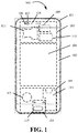
- FIG. 1 illustrates a structure diagram of a mobile terminal 100 according to an embodiment of the disclosure.
- the mobile terminal 100 includes a casing 101, a touch display screen 102, a mainboard 103, a battery 104, and an auxiliary board 105.
- a supplementary infrared light lamp 106, an iris camera 107, a front camera 108, a processor 109, a memory 110, a Subscriber Identity Module (SIM) card slot 111 and the like are arranged on the mainboard 103.
- a vibrator 112, an integrated sound cavity 113, a VOOC interface 114 and a fingerprint module 115 are arranged on the auxiliary board 105.
- the supplementary infrared light lamp 106 and the iris camera 107 form an iris information acquisition device of the mobile terminal 100.
- the front camera 108 forms a face information acquisition device of the mobile terminal 100.
- the fingerprint sensor module 115 forms a fingerprint information acquisition device of the mobile terminal 100.
- the iris information acquisition device, the face information acquisition device and the fingerprint information acquisition device are collectively referred to as a biological information acquisition device of the mobile terminal 100.
- the biological information acquisition device is the iris information acquisition device
- the supplementary infrared light lamp 106 is configured to emit infrared light to irradiate an iris of a user to form reflected light
- the iris camera 107 is configured to acquire the reflected light to form an iris image
- the processor 110 after acquiring the iris image, executes a processing process of iris image quality assessment, iris region positioning (including rough positioning and fine positioning), iris preprocessing and iris feature point extraction, generation of an iris template and the like for the iris image, and a generated iris template is biological information.
- acquisition of the biological information may be implementing by the biological information acquisition device acquiring a biological image of the user.
- the infrared acquisition device is configured to acquire an iris image of a current user.
- the memory is configured to store an iris image template.
- the processor 110 is configured to execute one or more actions, including: obtaining a current ambient brightness value of the mobile terminal, determining a target working mode of the infrared acquisition device according to the current ambient brightness value and acquiring the iris image of the current user in the target working mode via the infrared acquisition device.
- the mobile terminal obtains the current ambient brightness value of the mobile terminal at first, then determines the target working mode of the infrared acquisition device according to the current ambient brightness value and finally acquires the iris image of the current user in the target working mode via the infrared acquisition device.
- the mobile terminal determines the current ambient brightness value at first and determines the target working mode of the infrared acquisition device according to the ambient brightness value, which helps prompt a position of the infrared acquisition device to the user under lower ambient brightness, so that reliability and accuracy of the iris recognition of the mobile terminal are improved.
- the infrared acquisition device includes an infrared camera and a supplementary infrared light device.
- the supplementary infrared light device includes a supplementary infrared light lamp and a light filter (e.g., controllable light filter).
- Working modes of the infrared acquisition device include a first working mode and a second working mode. In the first working mode, infrared light emitted by the supplementary infrared light lamp is filtered through the controllable light filter; and in the second working mode, the infrared light emitted by the supplementary infrared light lamp is not filtered through the controllable light filter.
- the one or more actions may further include: in response to determination of the target working mode of the infrared acquisition device being the first working mode, locating the light filter to be aligned with the supplementary infrared light lamp in a light-emitting direction of the supplementary infrared light lamp (e.g., rotating the controllable light filter to be oriented towards a light-emitting direction of the supplementary infrared light lamp to result in that a contact area of the controllable light filter and the supplementary infrared light lamp is 1); or, in response to determination of the target working mode of the infrared acquisition device being the second working mode, locating the light filter to be non-overlap with the supplementary infrared light lamp when observed in the light-emitting direction of the supplementary infrared light lamp (e.g., rotate the controllable light filter to be oriented towards a non-light-emitting direction of the supplementary infrared light lamp to result in that the contact area of the controll
- the action of determining the target working mode of the infrared acquisition device according to the current ambient brightness value may include: determining the target working mode of the infrared acquisition device according to a pre-stored mapping relationship between the current ambient brightness value and the working modes of the infrared acquisition device.
- the action of determining the target working mode of the infrared acquisition device according to the pre-stored mapping relationship between the current ambient brightness value and the working modes of the infrared acquisition device may include: in response to obtaining of the current ambient brightness value being greater than or equal to a preset brightness threshold value, determining that the target working mode of the infrared acquisition device is the first working mode; and in response to obtaining of the current ambient brightness value being lower than the preset brightness threshold value, determining that the target working mode of the infrared acquisition device is the second working mode.
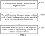
- FIG. 2 illustrates a flowchart of an iris image acquisition method according to an embodiment of the disclosure.
- the iris image acquisition method is applied to a mobile terminal, and as shown in the figure, includes the following operations illustrated in blocks. The operations may begin from block S201.
- the mobile terminal acquires a current ambient brightness value of the mobile terminal.
- the mobile terminal may acquire the current ambient brightness value through a sensor, for example, a light sensor.
- Ambient brightness in the embodiment of the disclosure may be ambient luminance, and for different places, different proper common luminance may usually be adopted.
- best luminance of a bedroom is usually 150-300Lux
- best luminance of a study room is usually about 100Lux
- luminance of a corridor and a staircase is usually 40-80Lux
- luminance of a garage and a warehouse is usually about 30-70Lux
- Lux is a unit of luminance.
- luminance generated on the ground is 0.2Lux, and at this moment, it is darker and ambient brightness is lower.
- the mobile terminal determines a target working mode of an infrared acquisition device according to the current ambient brightness value.
- the infrared acquisition device has greater than one working modes, and the specific working mode to be adopted by the infrared acquisition device may be determined according to the detected current ambient brightness value.
- the mobile terminal acquires an iris image of a current user in the target working mode via the infrared acquisition device.
- the infrared acquisition device may be switched to the target working mode to acquire the iris image of the user.
- the mobile terminal obtains the current ambient brightness value of the mobile terminal at first, then determines the target working mode of the infrared acquisition device according to the current ambient brightness value and finally acquires the iris image of the current user in the target working mode via the infrared acquisition device.
- the mobile terminal determines the current ambient brightness value at first and determines the target working mode of the infrared acquisition device according to the ambient brightness value, which helps prompt a position of the infrared acquisition device to the user under lower ambient brightness, so that reliability and accuracy of the iris recognition of the mobile terminal are improved.
- the infrared acquisition device includes an infrared camera and a supplementary infrared light device.
- the supplementary infrared light device includes a supplementary infrared light lamp and a controllable light filter.
- Working modes of the infrared acquisition device include a first working mode and a second working mode. In the first working mode, infrared light emitted by the supplementary infrared light lamp is filtered through the controllable light filter; and in the second working mode, the infrared light emitted by the supplementary infrared light lamp is not filtered through the controllable light filter.
- the infrared acquisition device may include the infrared camera and the supplementary infrared light device, the infrared camera is configured to acquire infrared light reflected by an iris of the user to form an iris image, and the supplementary infrared light device may emit the infrared light.
- the supplementary infrared light device may include the supplementary infrared light lamp and the controllable light filter.
- FIG. 3 is a possible schematic diagram of a light filter according to an embodiment of the disclosure, where 301 is the light filter.
- the supplementary infrared light lamp is configured to emit the infrared light
- the light filter is configured to filter the light of a specific part and allow the light of the other part to pass through.
- the visible light may be filtered by the light filter, only the infrared light is reserved, and at this moment, the user may not see any red light.
- transmittance of infrared light with a wavelength of greater than or equal to 810nm may be higher than 80%, and transmittance of visible light with a wavelength of smaller than 810nm may be lower than 5%.
- a position of the controllable light filter may be regulated, so that the infrared acquisition device has the two working modes. In the first working mode, the infrared light emitted by the supplementary infrared light lamp is filtered through the controllable light filter, and in the second working mode, the infrared light emitted by the supplementary infrared light lamp is not filtered through the controllable light filter.
- a position relationship between the controllable light filter and an infrared flashlight may be changed to implement switching between the first working mode and the second working mode.
- controllable light filter is added into the supplementary infrared light device to endow the supplementary infrared light device with the two working modes, namely using the light filter and not using the light filter, corresponding to different beneficial effects respectively, so that improvement of richness of functions of the supplementary infrared light device is facilitated.
- the operation of determining the target working mode of the infrared acquisition device according to the current ambient brightness value includes that: in response to determination of the target working mode of the infrared acquisition device being the first working mode, the light filter is located to be aligned with the supplementary infrared light lamp in a light-emitting direction of the supplementary infrared light lamp (e.g., the controllable light filter is rotated to be oriented towards a light-emitting direction of the supplementary infrared light lamp to result in that a contact area of the controllable light filter and the supplementary infrared light lamp is 1); or, in response to determination of the target working mode of the infrared acquisition device being the second working mode, the light filter is located to be non-overlap with the supplementary infrared light lamp when observed in the light-emitting direction of the supplementary infrared light lamp (e.g., the controllable light filter is rotated to be oriented towards a non-light-emitting
- the infrared light emitted by the supplementary infrared light lamp is filtered through the controllable light filter.
- a rotating base may be arranged for the controllable light filter, and when the light filter is located to be aligned with the supplementary infrared light lamp in a light-emitting direction of the supplementary infrared light lamp (e.g., the controllable light filter is rotated to be oriented with the light-emitting direction of the supplementary infrared light lamp) and the contact area of the controllable light filter and the supplementary infrared light lamp is 1, all the light emitted by the supplementary infrared light lamp may pass through the light filter at this moment, and the light filter may filter out visible light.
- the infrared light emitted by the supplementary infrared light lamp is not filtered through the controllable light filter.
- the light filter may be located to be non-overlap with the supplementary infrared light lamp when observed in the light-emitting direction of the supplementary infrared light lamp (e.g., the controllable light filter may be rotated to be oriented towards the non-light-emitting direction of the supplementary infrared light lamp), and at this moment, the contact area of the controllable light filter and the supplementary infrared light lamp is 0, and all the light emitted by the supplementary infrared light lamp may not pass through the light filter.
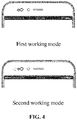
- FIG. 4 illustrates a schematic view when the infrared acquisition device works in the first working mode and the second working mode.
- Change of the position relationship between the controllable light filter and the supplementary infrared light lamp to implement switching between the first working mode and the second working mode may be implemented not only by controlling rotation of the controllable light filter but also by sliding the controllable light filter.
- the position relationship between the controllable light filter and the supplementary infrared light lamp is changed through a driving device to implement switching between the first working mode and the second working mode.
- the position of the controllable light filter is changed to implement switching between the first working mode and second working mode of the supplementary infrared light device, so that improvement of the richness of the functions of the supplementary infrared light device is facilitated.
- the operation of determining the target working mode of the infrared acquisition device according to the current ambient brightness value may include determining the target working mode of the infrared acquisition device according to a pre-stored mapping relationship between the current ambient brightness value and the working modes of the infrared acquisition device.
- the mobile terminal may establish a mapping relationship between ambient brightness and a working mode of the infrared acquisition device, and after the current ambient brightness value is determined, the mobile terminal may query the mapping relationship, thereby determining the target working mode of the infrared acquisition device.
- the user may establish a mapping relationship between a current ambient brightness value and a working mode of the infrared acquisition device in a customization manner, so that the mobile terminal may automatically switch the infrared acquisition device to the corresponding target working mode after the current ambient brightness value is determined, and improvement of a user experience is facilitated.
- the operation of determining the target working mode, of the infrared acquisition device according to the pre-stored mapping relationship between the current ambient brightness value and the working modes of the infrared acquisition device may include: in response to obtaining of the current ambient brightness value being greater than or equal to a preset brightness threshold value, determining that the target working mode is the first working mode; and in response to obtaining of the current ambient brightness value being lower than the preset brightness threshold value, determining the target working mode is the second working mode.
- the pre-stored mapping relationship between the ambient brightness value and the infrared camera may be that: when the ambient brightness value is greater than or equal to the preset brightness threshold value, the corresponding target working mode is the first working mode, and when the current ambient brightness value is lower than the preset brightness threshold value, the target working mode is the second working mode.
- the preset brightness threshold value is 1Lux
- the supplementary infrared light device may work in the second working mode, so that the user may see red light, and thus roughly know the position of the infrared acquisition device, and iris recognition may be performed.
- the supplementary infrared light device is switched to the second working mode under a low-light condition, and then the user may see visible red light emitted by the supplementary infrared light lamp, so that the position of the infrared acquisition device may be prompted, and improvement of accuracy of the iris image acquisition is facilitated.
- FIG. 5 illustrates a structure diagram of a mobile terminal according to an embodiment of the disclosure.
- the mobile terminal 500 includes a processor 501, a memory 502, a communication interface 503 and one or more programs 504, wherein the one or more programs 504 are stored in the memory 502, and are configured to be executed by the processor 501, and the programs include instructions configured to execute one or more action including: obtaining a current ambient brightness value of the mobile terminal; determining a target working mode of an infrared acquisition device according to the current ambient brightness value; and acquiring an iris image of a current user in the target working mode via the infrared acquisition device.
- the mobile terminal obtains the current ambient brightness value of the mobile terminal at first, then determines the target working mode of the infrared acquisition device according to the current ambient brightness value and finally acquires the iris image of the current user in the target working mode via the infrared acquisition device.
- the mobile terminal determines the current ambient brightness value at first and determines the target working mode of the infrared acquisition device according to the ambient brightness value, which helps prompt a position of the infrared acquisition device to the user under lower ambient brightness, so that reliability and accuracy of the iris recognition of the mobile terminal are improved.
- the infrared acquisition device includes an infrared camera and a supplementary infrared light device.
- the supplementary infrared light device includes a supplementary infrared light lamp and a controllable light filter.
- Working modes of the infrared acquisition device include a first working mode and a second working mode.
- infrared light emitted by the supplementary infrared light lamp is filtered through the controllable light filter.
- the infrared light emitted by the supplementary infrared light lamp is not filtered through the controllable light filter.
- the one or more actions further may further include: in response to determination of the target working mode of the infrared acquisition device being the first working mode, locating the light filter to be aligned with the supplementary infrared light lamp in a light-emitting direction of the supplementary infrared light lamp (e.g., rotating the controllable light filter to be oriented towards a light-emitting direction of the supplementary infrared light lamp to result in that a contact area of the controllable light filter and the supplementary infrared light lamp is 1); or, in response to determination of the target working mode of the infrared acquisition device being the second working mode, locating the light filter to be non-overlap with the supplementary infrared light lamp when observed in the light-emitting direction of the supplementary infrared light lamp (e.g., rotating the controllable light filter to be oriented towards a non-light-emitting direction of the supplementary infrared light lamp to result in that the contact area of the
- the action of determining the target working mode of the infrared acquisition device according to the current ambient brightness value may include: determining the target working mode of the infrared acquisition device according to a pre-stored mapping relationship between the current ambient brightness value and the working modes of the infrared acquisition device.
- the action of determining the target working mode of the infrared acquisition device according to the pre-stored mapping relationship between the ambient brightness values and the working modes of the infrared acquisition device may include: in response to obtaining of the current ambient brightness value being greater than or equal to a preset brightness threshold value, determining that the target working mode is the first working mode; and in response to obtaining of the current ambient brightness value being lower than the preset brightness threshold value, determining that the target working mode is the second working mode.
- the mobile terminal for realizing the functions, includes a corresponding hardware structure and/or software module executing each function.
- the units or algorithm steps of each example described in combination with the embodiments disclosed in the disclosure may be implemented in form of hardware or a combination of the hardware and computer software in the disclosure. Whether a certain function is executed in a manner of hardware or driving the hardware by computer software depends on specific applications and design constraints of the technical solutions. Professionals may realize the described functions for each specific application by virtue of different methods, but such realization shall fall within the scope of the disclosure.
- Function units of the mobile terminal may be divided according to the abovementioned method examples in the embodiment of the disclosure.
- each function unit corresponding to each function may be divided, and two or greater than two functions may also be integrated into a processing unit.
- the integrated unit may be implemented in form of hardware and may also be implemented in form of software function unit. It is to be noted that division of the units in the embodiment of the disclosure is only schematic and is only logic function division, and another division manner may be adopted during practical implementation.
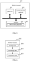
- FIG. 6 illustrates a possible composition block diagram of function units of the mobile terminal involved in the embodiment.
- the mobile terminal 600 includes a processing unit 602 and an acquisition unit 603.
- the processing unit 602 is configured to perform control and management on actions of the mobile terminal.
- the processing unit 602 is configured to support the mobile terminal to execute blocks S201-S203 in FIG. 2 and/or is configured for other processes of a technology described in the disclosure.
- the acquisition unit 603 is configured to support communication between the mobile terminal and other equipment.
- the mobile terminal may further include a storage unit 601, configured to store program codes and data of the mobile terminal.
- the processing unit 602 is configured to obtain a current ambient brightness value of the mobile terminal, is configured to determine a target working mode of an infrared acquisition device according to the current ambient brightness value, and is configured to acquire an iris image of a current user in the target working mode via the acquisition unit in the infrared acquisition device.
- the infrared acquisition device includes an infrared camera and a supplementary infrared light device.
- the supplementary infrared light device includes a supplementary infrared light lamp and a controllable light filter.
- Working modes of the infrared acquisition device include a first working mode and a second working mode. In the first working mode, infrared light emitted by the supplementary infrared light lamp is filtered through the controllable light filter; and in the second working mode, the infrared light emitted by the supplementary infrared light lamp is not filtered through the controllable light filter.
- the processing unit 602 is specifically configured to: in response to determination of the target working mode of the infrared acquisition device being the first working mode, locate the light filter to be aligned with the supplementary infrared light lamp in a light-emitting direction of the supplementary infrared light lamp (e.g., rotate the controllable light filter to be oriented towards a light-emitting direction of the supplementary infrared light lamp to result in that a contact area of the controllable light filter and the supplementary infrared light lamp is 1); or, in response to determination of the target working mode of the infrared acquisition device being the second working mode, locate the light filter to be non-overlap with the supplementary infrared light lamp when observed in the light-emitting direction of the supplementary infrared light lamp (e.g., rotate the controllable light filter to be oriented towards a non-light-
- the processing unit 602 is specifically configured to determine the target working mode of the infrared acquisition device according to a pre-stored mapping relationship between the current ambient brightness value and the working modes of the infrared acquisition device.
- the processing unit 602 is specifically configured to: in response to obtaining of the current ambient brightness value being greater than or equal to a preset brightness threshold value, determine that the target working mode is the first working mode; and in response to obtaining of the current ambient brightness value being lower than the preset brightness threshold value, determine that the target working mode is the second working mode.
- the processing unit 602 may be a processor or a controller
- the acquisition unit 603 may be a biological information acquisition device, for example, an iris information acquisition device, a face information acquisition device and a fingerprint information acquisition device
- the storage unit 601 may be a memory.
- An embodiment of the disclosure further provides a computer storage medium, wherein the computer storage medium stores a computer program for electronic data exchange, the computer program enables a computer to execute part or all of operations of any method recorded in the abovementioned method embodiments, and the computer includes a mobile terminal.
- FIG. 7 illustrates a structure diagram of a mobile terminal 700 according to an embodiment of the disclosure.
- the mobile terminal 700 is an implementation of the mobile terminal 500 as illustrated in FIG. 5 .
- the mobile terminal includes a processor 701, a memory 702, and an infrared acquisition device 703 connected with the processor 701.
- the infrared acquisition device 703 is configured to acquire an iris image of a current user.
- the memory 702 is configured to store an iris image template.
- the processor 701 is configured to execute one or more actions, including: obtaining a current ambient brightness value of the mobile terminal, determining a target working mode of the infrared acquisition device according to the current ambient brightness value, and acquiring the iris image of the current user in the target working mode via the infrared acquisition device.
- the infrared acquisition device 703 may include an infrared camera 7031 and a supplementary infrared light device 7032.
- the supplementary infrared light device 7032 may include a supplementary infrared light lamp 70321 and a light filter 70322.
- Working modes of the infrared acquisition device 703 includes a first working mode and a second working mode. In the first working mode, infrared light emitted by the supplementary infrared light lamp 70321 is filtered through the light filter 70322. In the second working mode, the infrared light emitted by the supplementary infrared light lamp 70321 is not filtered through the light filter 70322.
- the one or more actions may further include: in response to determination of the target working mode of the infrared acquisition being the first working mode, locating the light filter 70322 to be aligned with the supplementary infrared light lamp 70321 in a light-emitting direction of the supplementary infrared light lamp 70321; or, in response to determination of the target working mode of the infrared acquisition being the second working mode, locating the light filter 70322 to be non-overlap with the supplementary infrared light lamp 70321 when observed in the light-emitting direction of the supplementary infrared light lamp 70321.
- the action of determining the target working mode of the infrared acquisition device according to the current ambient brightness value may include determining the target working mode of the infrared acquisition device according to a pre-stored mapping relationship between the current ambient brightness value and the working modes of the infrared acquisition device.
- the action of determining the target working mode of the infrared acquisition device according to the pre-stored mapping relationship between the current ambient brightness value and the working modes of the infrared acquisition device may include: in response to obtaining of the current ambient brightness value being greater than or equal to a preset brightness threshold value, determine that the target working mode is the first working mode; and in response to obtaining of the current ambient brightness value being lower than the preset brightness threshold value, determine that the target working mode is the second working mode.
- the mobile terminal may further include a driving device 704 controlled by the processor 701 and connected to the light filter 70322, the processor 701 is configured to change a relative position relationship between the light filter 70322 and the supplementary infrared light lamp 70321 by performing rotation control or sliding control over the light filter 70322 through the driving device 704, so as to implement switching between the first working mode and the second working mode.
- a driving device 704 controlled by the processor 701 and connected to the light filter 70322
- the processor 701 is configured to change a relative position relationship between the light filter 70322 and the supplementary infrared light lamp 70321 by performing rotation control or sliding control over the light filter 70322 through the driving device 704, so as to implement switching between the first working mode and the second working mode.
- the processor 701 may be further configured to perform iris image quality assessment, iris region positioning, iris preprocessing and iris feature point extraction, so as to generate the iris template, after the iris image is acquired.
- An embodiment of the disclosure further provides a computer program product
- the computer program product includes a non-transitory computer-readable storage medium storing a computer program
- the computer program may be operated to enable a computer to execute part or all of operations of any method recorded in the abovementioned method embodiments.
- the computer program product may be a software installation packet, and the computer includes a mobile terminal.
- each method embodiment is expressed as a combination of a series of actions.
- the disclosure is not limited to a described action sequence, and this is because, according to the disclosure, some operations may be executed in another sequence or at the same time.
- those skilled in the art should also know that all of the embodiments described in the specification belong to preferred embodiments and involved actions and modules are not always necessary to the disclosure.
- each embodiment is described with different emphases and parts which are not elaborated in a certain embodiment may refer to related descriptions in the other embodiments.
- the disclosed device may be implemented in another manner.
- the device embodiment described above is only schematic, and for example, division of the units is only logic function division, and other division manners may be adopted during practical implementation.
- multiple units or components may be combined or integrated into another system, or some characteristics may be neglected or not executed.
- coupling or direct coupling or communication connection between each displayed or discussed component may be indirect coupling or communication connection, implemented through some interfaces, of the device or the units, and may be electrical or adopt other forms.
- the units described as separate parts may or may not be physically separated, and parts displayed as units may or may not be physical units, and namely may be located in the same place, or may also be distributed to multiple network units. Part or all of the units may be selected to achieve the purpose of the solutions of the embodiments according to a practical requirement.
- each function unit in each embodiment of the disclosure may be integrated into a processing unit, each unit may also physically exist independently, and two or greater than two units may also be integrated into a unit.
- the integrated unit may be implemented in form of hardware and may also be implemented in form of software function unit.
- the unit When being implemented in form of software function unit and sold or used as an independent product, the unit may be stored in a computer-readable storage medium.
- the technical solutions of the disclosure substantially or parts making contributions to the conventional art or all or part of the technical solutions may be embodied in form of software product, and the computer software product is stored in a memory, including a plurality of instructions configured to enable a piece of computer equipment (which may be a personal computer, a server, network equipment or the like) to execute all or part of the operations of the method in each embodiment of the disclosure.
- the memory includes: various media capable of storing program codes such as a U disk, a Read-Only Memory (ROM), a Random Access Memory (RAM), a mobile hard disk, a magnetic disk or an optical disk.
- the program may be stored in a computer-readable memory, and the memory may include: a flash disk, a ROM, a RAM, a magnetic disk, an optical disk or the like.
Landscapes
- Engineering & Computer Science (AREA)
- Physics & Mathematics (AREA)
- General Physics & Mathematics (AREA)
- Theoretical Computer Science (AREA)
- Multimedia (AREA)
- Health & Medical Sciences (AREA)
- General Health & Medical Sciences (AREA)
- Ophthalmology & Optometry (AREA)
- Human Computer Interaction (AREA)
- Computer Hardware Design (AREA)
- Vascular Medicine (AREA)
- Computer Vision & Pattern Recognition (AREA)
- Studio Devices (AREA)
- Telephone Function (AREA)
- Eye Examination Apparatus (AREA)
- Measurement Of The Respiration, Hearing Ability, Form, And Blood Characteristics Of Living Organisms (AREA)
Abstract
Description
- The disclosure relates to the technical field of mobile terminals, and more particularly to an iris image acquisition method, a mobile terminal and storage medium.
- Along with progress of the society and development of sciences, information interaction occurs more and more frequently. For ensuring security of information, an identity of a user is required to be verified. Therefore, recognition technologies such as fingerprint recognition, face recognition, iris recognition, vein recognition, palmprint recognition and the like are usually applied.
- Embodiments of the disclosure provide an iris image acquisition method, a mobile terminal and storage medium, which may improve precision, comprehensiveness and flexibility of security management of a mobile terminal.
- At a first aspect, the embodiments of the disclosure provide a mobile terminal, which may include a processor, an infrared acquisition device connected with the processor, a memory, wherein the infrared acquisition device may be configured to acquire an iris image of a current user; the memory may be configured to store an iris image template; and the processor may be configured to execute one or more actions, including obtaining a current ambient brightness value of the mobile terminal, determining a target working mode of the infrared acquisition device according to the current ambient brightness value and acquiring the iris image of the current user in the target working mode via the infrared acquisition device.
- In some embodiments, the infrared acquisition device may include an infrared camera and a supplementary infrared light device. The supplementary infrared light device may include a supplementary infrared light lamp and a light filter. Working modes of the infrared acquisition device may include a first working mode and a second working mode. In the first working mode, infrared light emitted by the supplementary infrared light lamp is filtered through the light filter; and in the second working mode, the infrared light emitted by the supplementary infrared light lamp is not filtered through the light filter.
- In some embodiments, the one or more actions may further include: in response to determination of the target working mode of the infrared acquisition device being the first working mode, locating the light filter to be aligned with the supplementary infrared light lamp in a light-emitting direction of the supplementary infrared light lamp.
- In some embodiments, the one or more actions may further include: in response to determination of the target working mode of the infrared acquisition device being the second working mode, locating the light filter to be non-overlap with the supplementary infrared light lamp when observed in the light-emitting direction of the supplementary infrared light lamp.
- In some embodiments, the action of determining the target working mode of the infrared acquisition device according to the current ambient brightness value may include determining the target working mode of the infrared acquisition device according to a pre-stored mapping relationship between the current ambient brightness value and the working modes of the infrared acquisition device.
- In some embodiments, the action of determining the target working mode of the infrared acquisition device according to a pre-stored mapping relationship between the current ambient brightness value and the working modes of the infrared acquisition device may include in response to obtaining of the current ambient brightness value being greater than or equal to a preset brightness threshold value, determining that the target working mode is the first working mode; and in response to obtaining of the current ambient brightness value being lower than the preset brightness threshold value, determining that the target working mode is the second working mode.
- In some embodiments, the mobile terminal may further include a driving device controlled by the processor and connected to the light filter, the one or more actions may further include changing a relative position relationship between the light filter and the supplementary infrared light lamp by performing rotation control or sliding control over the light filter through the driving device, so as to implement switching between the first working mode and the second working mode.
- In some embodiments, the one or more actions may further include performing iris image quality assessment, iris region positioning, iris preprocessing and iris feature point extraction, so as to generate the iris template, after the iris image is acquired.
- At a second aspect, the embodiments of the disclosure provide an iris image acquisition method, which may include that: a current ambient brightness value of a mobile terminal is acquired; a target working mode of an infrared acquisition device is determined according to the current ambient brightness value; and an iris image of a current user is acquired in the target working mode via the infrared acquisition device.
- In some embodiments, the infrared acquisition device may include an infrared camera and a supplementary infrared light device. The supplementary infrared light device may include a supplementary infrared light lamp and a light filter. Working modes of the infrared acquisition device comprise a first working mode and a second working mode. In the first working mode, infrared light emitted by the supplementary infrared light lamp is filtered through the light filter; and in the second working mode, the infrared light emitted by the supplementary infrared light lamp is not filtered through the light filter.
- In some embodiments, the action of determining the target working mode of the infrared acquisition device according to the current ambient brightness value may include in response to determination of the target working mode being the first working mode, locating the light filter to be aligned with the supplementary infrared light lamp in a light-emitting direction of the supplementary infrared light lamp.
- In some embodiments, the action of determining the target working mode of the infrared acquisition device according to the current ambient brightness value may include in response to determination of the target working mode being the second working mode, locating the light filter to be non-overlap with the supplementary infrared light lamp when observed in the light-emitting direction of the supplementary infrared light lamp.
- In some embodiments, the action of determining the target working mode of the infrared acquisition device according to the current ambient brightness value may include determining the target working mode of the infrared acquisition device according to a pre-stored mapping relationship between the current ambient brightness value and the working modes of the infrared acquisition device.
- In some embodiments, the action of determining the target working mode of the infrared acquisition device according to the pre-stored mapping relationship between the current ambient brightness value and the working modes of the infrared acquisition device may include: in response to obtaining of the current ambient brightness value being greater than or equal to a preset brightness threshold value, determining that the target working mode is the first working mode; and in response to obtaining of the current ambient brightness value being lower than the preset brightness threshold value, determining that the target working mode is the second working mode.
- In some embodiments, the mobile terminal may further include a driving device controlled by the processor and connected to the light filter, and the action of controlling the infrared acquisition device to acquire an iris image of a current user in the target working mode may include: changing a relative position relationship between the light filter and the supplementary infrared light lamp by performing rotation control or sliding control over the light filter through the driving device, so as to implement switching between the first working mode and the second working mode.
- In some embodiments, the method may further include performing iris image quality assessment, iris region positioning, iris preprocessing and iris feature point extraction, to generate an iris template, after the iris image is acquired.
- At a third aspect, the embodiments of the disclosure provide a computer-readable storage medium, wherein the computer-readable storage medium may store a computer program, which, when being executed by a processor, causes the processor to execute part or all of operations described in any method of the first aspect of the embodiments of the disclosure, and the computer may include a mobile terminal.
- According to the embodiments of the disclosure, the mobile terminal obtains the current ambient brightness value of the mobile terminal at first, then determines the target working mode of the infrared acquisition device according to the current ambient brightness value and finally acquires the iris image of the current user in the target working mode via the infrared acquisition device. Before iris recognition, the mobile terminal determines the current ambient brightness value at first and determines the target working mode of the infrared acquisition device according to the ambient brightness value, which helps prompt a position of the infrared acquisition device to the user under lower ambient brightness, so that reliability and accuracy of the iris recognition of the mobile terminal are improved.
- The drawings involved in the embodiments of the disclosure will be simply introduced below.
-
FIG. 1 illustrates a structure diagram of a mobile terminal according to an embodiment of the disclosure. -
FIG. 2 illustrates a flowchart of an iris image acquisition method according to an embodiment of the disclosure. -
FIG. 3 illustrates an example structure diagram of a mobile terminal including a controllable light filter according to an embodiment of the disclosure. -
FIG. 4 illustrates a schematic view of a first working mode and a second working mode according to an embodiment of the disclosure. -
FIG. 5 illustrates a structure diagram of a mobile terminal according to an embodiment of the disclosure. -
FIG. 6 illustrates a composition block diagram of function units of a mobile terminal according to an embodiment of the disclosure. -
FIG. 7 illustrates a structure diagram of a mobile terminal according to an embodiment of the disclosure. - For making the solutions of the disclosure better understood by those skilled in the art, the technical solutions in the embodiments of the disclosure will be clearly and completely described below in combination with the drawings in the embodiments of the disclosure. Obviously, the described embodiments are not all embodiments but part of embodiments of the disclosure. All other embodiments obtained by those of ordinary skilled in the art on the basis of the embodiments in the disclosure without creative work shall fall within the scope of protection of the disclosure.
- Terms "first", "second" and the like in the specification, claims and drawings of the disclosure are adopted not to describe a specific sequence but to distinguish different objects. In addition, terms "include" and "have" and any transformation thereof are intended to cover nonexclusive inclusions. For example, a process, method, system, product or equipment including a series of operations or units is not limited to the operations or units which are listed, but further optionally includes operations or units which are not listed or further optionally includes other operations or units intrinsic to the process, the method, the product or the equipment.
- "Embodiment" mentioned in the disclosure means that a specific characteristic, structure or feature described in combination with the embodiment may be included in at least one embodiment of the disclosure. The phrase appearing at each position in the specification does not always refer to the same embodiment as well as an independent or alternate embodiment mutually exclusive with the other embodiments. Those skilled in the art explicitly and implicitly understand that the embodiments described in the invention may be combined with the other embodiments.
- At present, an iris information acquisition device includes a supplementary infrared light lamp and an infrared camera, and a wavelength of the infrared lamp is about 810nm. Since it is difficult to narrow the frequency spectrum of the infrared lamp, 780nm visible light beside may be driven to work together, such that a user may see red light, which influences the appearance vision. According to the iris image acquisition method, mobile terminal and storage medium provided by the embodiments of the disclosure, the target working mode of the iris acquisition device may be determined according to the current ambient brightness value. When the ambient brightness value is high, the red light may be filtered out to avoid influences on the appearance vision. When the ambient brightness value is low, the red light is used to prompt a position of the infrared acquisition device to the user. Therefore, reliability and accuracy of the iris recognition of the mobile terminal are improved.
- A mobile terminal involved in the embodiments of the disclosure may include various kinds of handheld equipment with a wireless communication function, vehicle-mounted equipment, wearable equipment, computing equipment or other processing equipment connected to a wireless modem and various forms of User Equipment (UE), Mobile Stations (MSs), terminal devices and the like. For convenient description, the equipment mentioned above is collectively referred to as mobile terminal.
- The mobile terminal described in the embodiments of the disclosure is provided with a biological image acquisition device, and the biological image acquisition device specifically includes a fingerprint information acquisition device, an iris information acquisition device and a face information acquisition device, the fingerprint information acquisition device may be a fingerprint sensor, the iris information acquisition device may include a supplementary infrared light lamp and an iris camera, and the face information acquisition device may be a universal camera, for example, a front camera. The embodiments of the disclosure will be introduced below in combination with the drawings in detail.
- Turning to
FIG. 1, FIG. 1 illustrates a structure diagram of amobile terminal 100 according to an embodiment of the disclosure. Themobile terminal 100 includes acasing 101, atouch display screen 102, amainboard 103, abattery 104, and anauxiliary board 105. A supplementaryinfrared light lamp 106, aniris camera 107, afront camera 108, aprocessor 109, amemory 110, a Subscriber Identity Module (SIM)card slot 111 and the like are arranged on themainboard 103. Avibrator 112, anintegrated sound cavity 113, aVOOC interface 114 and afingerprint module 115 are arranged on theauxiliary board 105. The supplementary infraredlight lamp 106 and theiris camera 107 form an iris information acquisition device of themobile terminal 100. Thefront camera 108 forms a face information acquisition device of themobile terminal 100. Thefingerprint sensor module 115 forms a fingerprint information acquisition device of themobile terminal 100. The iris information acquisition device, the face information acquisition device and the fingerprint information acquisition device are collectively referred to as a biological information acquisition device of themobile terminal 100. - When the biological information acquisition device is the iris information acquisition device, the supplementary infrared
light lamp 106 is configured to emit infrared light to irradiate an iris of a user to form reflected light, theiris camera 107 is configured to acquire the reflected light to form an iris image, and theprocessor 110, after acquiring the iris image, executes a processing process of iris image quality assessment, iris region positioning (including rough positioning and fine positioning), iris preprocessing and iris feature point extraction, generation of an iris template and the like for the iris image, and a generated iris template is biological information. - Specifically, acquisition of the biological information may be implementing by the biological information acquisition device acquiring a biological image of the user.
- The infrared acquisition device is configured to acquire an iris image of a current user.
- The memory is configured to store an iris image template.
- The
processor 110 is configured to execute one or more actions, including: obtaining a current ambient brightness value of the mobile terminal, determining a target working mode of the infrared acquisition device according to the current ambient brightness value and acquiring the iris image of the current user in the target working mode via the infrared acquisition device. - It can be seen that, in the embodiment of the disclosure, the mobile terminal obtains the current ambient brightness value of the mobile terminal at first, then determines the target working mode of the infrared acquisition device according to the current ambient brightness value and finally acquires the iris image of the current user in the target working mode via the infrared acquisition device. Before iris recognition, the mobile terminal determines the current ambient brightness value at first and determines the target working mode of the infrared acquisition device according to the ambient brightness value, which helps prompt a position of the infrared acquisition device to the user under lower ambient brightness, so that reliability and accuracy of the iris recognition of the mobile terminal are improved.
- In a possible example, the infrared acquisition device includes an infrared camera and a supplementary infrared light device. The supplementary infrared light device includes a supplementary infrared light lamp and a light filter (e.g., controllable light filter). Working modes of the infrared acquisition device include a first working mode and a second working mode. In the first working mode, infrared light emitted by the supplementary infrared light lamp is filtered through the controllable light filter; and in the second working mode, the infrared light emitted by the supplementary infrared light lamp is not filtered through the controllable light filter.
- In the possible example, the one or more actions may further include: in response to determination of the target working mode of the infrared acquisition device being the first working mode, locating the light filter to be aligned with the supplementary infrared light lamp in a light-emitting direction of the supplementary infrared light lamp (e.g., rotating the controllable light filter to be oriented towards a light-emitting direction of the supplementary infrared light lamp to result in that a contact area of the controllable light filter and the supplementary infrared light lamp is 1); or, in response to determination of the target working mode of the infrared acquisition device being the second working mode, locating the light filter to be non-overlap with the supplementary infrared light lamp when observed in the light-emitting direction of the supplementary infrared light lamp (e.g., rotate the controllable light filter to be oriented towards a non-light-emitting direction of the supplementary infrared light lamp to result in that the contact area of the controllable light filter and the supplementary infrared light lamp is 0).
- In a possible example, the action of determining the target working mode of the infrared acquisition device according to the current ambient brightness value may include: determining the target working mode of the infrared acquisition device according to a pre-stored mapping relationship between the current ambient brightness value and the working modes of the infrared acquisition device.
- In the possible example, the action of determining the target working mode of the infrared acquisition device according to the pre-stored mapping relationship between the current ambient brightness value and the working modes of the infrared acquisition device may include: in response to obtaining of the current ambient brightness value being greater than or equal to a preset brightness threshold value, determining that the target working mode of the infrared acquisition device is the first working mode; and in response to obtaining of the current ambient brightness value being lower than the preset brightness threshold value, determining that the target working mode of the infrared acquisition device is the second working mode.
- Turning to
FIG. 2, FIG. 2 illustrates a flowchart of an iris image acquisition method according to an embodiment of the disclosure. The iris image acquisition method is applied to a mobile terminal, and as shown in the figure, includes the following operations illustrated in blocks. The operations may begin from block S201. - In block S201, the mobile terminal acquires a current ambient brightness value of the mobile terminal.
- Herein, the mobile terminal may acquire the current ambient brightness value through a sensor, for example, a light sensor.
- When the mobile terminal is located in different environments or places, different ambient brightness values may be detected. Ambient brightness in the embodiment of the disclosure may be ambient luminance, and for different places, different proper common luminance may usually be adopted. For example, best luminance of a bedroom is usually 150-300Lux, best luminance of a study room is usually about 100Lux, luminance of a corridor and a staircase is usually 40-80Lux, and luminance of a garage and a warehouse is usually about 30-70Lux, where Lux is a unit of luminance. Under a full moon, luminance generated on the ground is 0.2Lux, and at this moment, it is darker and ambient brightness is lower.
- In block S202, the mobile terminal determines a target working mode of an infrared acquisition device according to the current ambient brightness value.
- Herein, the infrared acquisition device has greater than one working modes, and the specific working mode to be adopted by the infrared acquisition device may be determined according to the detected current ambient brightness value.
- In block S203, the mobile terminal acquires an iris image of a current user in the target working mode via the infrared acquisition device.
- Herein, after the target working mode of the infrared acquisition device is determined, the infrared acquisition device may be switched to the target working mode to acquire the iris image of the user.
- It can be seen that, in the embodiment of the disclosure, the mobile terminal obtains the current ambient brightness value of the mobile terminal at first, then determines the target working mode of the infrared acquisition device according to the current ambient brightness value and finally acquires the iris image of the current user in the target working mode via the infrared acquisition device. Before iris recognition, the mobile terminal determines the current ambient brightness value at first and determines the target working mode of the infrared acquisition device according to the ambient brightness value, which helps prompt a position of the infrared acquisition device to the user under lower ambient brightness, so that reliability and accuracy of the iris recognition of the mobile terminal are improved.
- In a possible example, the infrared acquisition device includes an infrared camera and a supplementary infrared light device. The supplementary infrared light device includes a supplementary infrared light lamp and a controllable light filter. Working modes of the infrared acquisition device include a first working mode and a second working mode. In the first working mode, infrared light emitted by the supplementary infrared light lamp is filtered through the controllable light filter; and in the second working mode, the infrared light emitted by the supplementary infrared light lamp is not filtered through the controllable light filter.
- The infrared acquisition device may include the infrared camera and the supplementary infrared light device, the infrared camera is configured to acquire infrared light reflected by an iris of the user to form an iris image, and the supplementary infrared light device may emit the infrared light.
- The supplementary infrared light device may include the supplementary infrared light lamp and the controllable light filter.
FIG. 3 is a possible schematic diagram of a light filter according to an embodiment of the disclosure, where 301 is the light filter. The supplementary infrared light lamp is configured to emit the infrared light, and the light filter is configured to filter the light of a specific part and allow the light of the other part to pass through. - When a wavelength of the infrared lamp is 810nm, since it is difficult to narrow a frequency spectrum of the infrared lamp, 780nm visible light beside may be driven to work together, such that the user may see red light, which influences appearance vision of the user. Therefore, the visible light may be filtered by the light filter, only the infrared light is reserved, and at this moment, the user may not see any red light.
- For the controllable light filter, transmittance of infrared light with a wavelength of greater than or equal to 810nm may be higher than 80%, and transmittance of visible light with a wavelength of smaller than 810nm may be lower than 5%.
- A position of the controllable light filter may be regulated, so that the infrared acquisition device has the two working modes. In the first working mode, the infrared light emitted by the supplementary infrared light lamp is filtered through the controllable light filter, and in the second working mode, the infrared light emitted by the supplementary infrared light lamp is not filtered through the controllable light filter. A position relationship between the controllable light filter and an infrared flashlight may be changed to implement switching between the first working mode and the second working mode.
- It can be seen that, in the example, the controllable light filter is added into the supplementary infrared light device to endow the supplementary infrared light device with the two working modes, namely using the light filter and not using the light filter, corresponding to different beneficial effects respectively, so that improvement of richness of functions of the supplementary infrared light device is facilitated.
- In the possible example, the operation of determining the target working mode of the infrared acquisition device according to the current ambient brightness value includes that: in response to determination of the target working mode of the infrared acquisition device being the first working mode, the light filter is located to be aligned with the supplementary infrared light lamp in a light-emitting direction of the supplementary infrared light lamp (e.g., the controllable light filter is rotated to be oriented towards a light-emitting direction of the supplementary infrared light lamp to result in that a contact area of the controllable light filter and the supplementary infrared light lamp is 1); or, in response to determination of the target working mode of the infrared acquisition device being the second working mode, the light filter is located to be non-overlap with the supplementary infrared light lamp when observed in the light-emitting direction of the supplementary infrared light lamp (e.g., the controllable light filter is rotated to be oriented towards a non-light-emitting direction of the supplementary infrared light lamp to result in that the contact area of the controllable light filter and the supplementary infrared light lamp is 0).
- In the first working mode, the infrared light emitted by the supplementary infrared light lamp is filtered through the controllable light filter. For implementing the first working mode of the infrared acquisition device, a rotating base may be arranged for the controllable light filter, and when the light filter is located to be aligned with the supplementary infrared light lamp in a light-emitting direction of the supplementary infrared light lamp (e.g., the controllable light filter is rotated to be oriented with the light-emitting direction of the supplementary infrared light lamp) and the contact area of the controllable light filter and the supplementary infrared light lamp is 1, all the light emitted by the supplementary infrared light lamp may pass through the light filter at this moment, and the light filter may filter out visible light. In the second working mode, the infrared light emitted by the supplementary infrared light lamp is not filtered through the controllable light filter. For implementing the second working mode of the infrared acquisition device, the light filter may be located to be non-overlap with the supplementary infrared light lamp when observed in the light-emitting direction of the supplementary infrared light lamp (e.g., the controllable light filter may be rotated to be oriented towards the non-light-emitting direction of the supplementary infrared light lamp), and at this moment, the contact area of the controllable light filter and the supplementary infrared light lamp is 0, and all the light emitted by the supplementary infrared light lamp may not pass through the light filter.
FIG. 4 illustrates a schematic view when the infrared acquisition device works in the first working mode and the second working mode. - Change of the position relationship between the controllable light filter and the supplementary infrared light lamp to implement switching between the first working mode and the second working mode, may be implemented not only by controlling rotation of the controllable light filter but also by sliding the controllable light filter. The position relationship between the controllable light filter and the supplementary infrared light lamp is changed through a driving device to implement switching between the first working mode and the second working mode.
- It can be seen that, in the example, the position of the controllable light filter is changed to implement switching between the first working mode and second working mode of the supplementary infrared light device, so that improvement of the richness of the functions of the supplementary infrared light device is facilitated.
- In a possible example, the operation of determining the target working mode of the infrared acquisition device according to the current ambient brightness value may include determining the target working mode of the infrared acquisition device according to a pre-stored mapping relationship between the current ambient brightness value and the working modes of the infrared acquisition device.
- Regarding determination of the target working mode of the infrared acquisition device according to the current ambient brightness value, the mobile terminal may establish a mapping relationship between ambient brightness and a working mode of the infrared acquisition device, and after the current ambient brightness value is determined, the mobile terminal may query the mapping relationship, thereby determining the target working mode of the infrared acquisition device.
- It can be seen that, in the example, the user may establish a mapping relationship between a current ambient brightness value and a working mode of the infrared acquisition device in a customization manner, so that the mobile terminal may automatically switch the infrared acquisition device to the corresponding target working mode after the current ambient brightness value is determined, and improvement of a user experience is facilitated.
- In the possible example, the operation of determining the target working mode, of the infrared acquisition device according to the pre-stored mapping relationship between the current ambient brightness value and the working modes of the infrared acquisition device may include: in response to obtaining of the current ambient brightness value being greater than or equal to a preset brightness threshold value, determining that the target working mode is the first working mode; and in response to obtaining of the current ambient brightness value being lower than the preset brightness threshold value, determining the target working mode is the second working mode.
- The pre-stored mapping relationship between the ambient brightness value and the infrared camera may be that: when the ambient brightness value is greater than or equal to the preset brightness threshold value, the corresponding target working mode is the first working mode, and when the current ambient brightness value is lower than the preset brightness threshold value, the target working mode is the second working mode. For example, the preset brightness threshold value is 1Lux, and when the user is in a darker environment and, meanwhile, ambient brightness is lower than 1Lux, the user may not see clearly a position of the infrared camera during iris recognition, so that accuracy of iris image acquisition may be influenced. At this moment, the supplementary infrared light device may work in the second working mode, so that the user may see red light, and thus roughly know the position of the infrared acquisition device, and iris recognition may be performed.
- It can be seen that, in the example, the supplementary infrared light device is switched to the second working mode under a low-light condition, and then the user may see visible red light emitted by the supplementary infrared light lamp, so that the position of the infrared acquisition device may be prompted, and improvement of accuracy of the iris image acquisition is facilitated.
- Consistently with the embodiment shown in
FIG. 2 , Turning toFIG. 5, FIG. 5 illustrates a structure diagram of a mobile terminal according to an embodiment of the disclosure. As shown in the figure, themobile terminal 500 includes aprocessor 501, amemory 502, acommunication interface 503 and one ormore programs 504, wherein the one ormore programs 504 are stored in thememory 502, and are configured to be executed by theprocessor 501, and the programs include instructions configured to execute one or more action including: obtaining a current ambient brightness value of the mobile terminal; determining a target working mode of an infrared acquisition device according to the current ambient brightness value; and acquiring an iris image of a current user in the target working mode via the infrared acquisition device. - It can be seen that, in the embodiment of the disclosure, the mobile terminal obtains the current ambient brightness value of the mobile terminal at first, then determines the target working mode of the infrared acquisition device according to the current ambient brightness value and finally acquires the iris image of the current user in the target working mode via the infrared acquisition device. Before iris recognition, the mobile terminal determines the current ambient brightness value at first and determines the target working mode of the infrared acquisition device according to the ambient brightness value, which helps prompt a position of the infrared acquisition device to the user under lower ambient brightness, so that reliability and accuracy of the iris recognition of the mobile terminal are improved.
- In a possible example, the infrared acquisition device includes an infrared camera and a supplementary infrared light device. The supplementary infrared light device includes a supplementary infrared light lamp and a controllable light filter. Working modes of the infrared acquisition device include a first working mode and a second working mode.
- In the first working mode, infrared light emitted by the supplementary infrared light lamp is filtered through the controllable light filter.
- In the second working mode, the infrared light emitted by the supplementary infrared light lamp is not filtered through the controllable light filter.
- In a possible example, the one or more actions further may further include: in response to determination of the target working mode of the infrared acquisition device being the first working mode, locating the light filter to be aligned with the supplementary infrared light lamp in a light-emitting direction of the supplementary infrared light lamp (e.g., rotating the controllable light filter to be oriented towards a light-emitting direction of the supplementary infrared light lamp to result in that a contact area of the controllable light filter and the supplementary infrared light lamp is 1); or, in response to determination of the target working mode of the infrared acquisition device being the second working mode, locating the light filter to be non-overlap with the supplementary infrared light lamp when observed in the light-emitting direction of the supplementary infrared light lamp (e.g., rotating the controllable light filter to be oriented towards a non-light-emitting direction of the supplementary infrared light lamp to result in that the contact area of the controllable light filter and the supplementary infrared light lamp is 0).
- In a possible example, the action of determining the target working mode of the infrared acquisition device according to the current ambient brightness value may include: determining the target working mode of the infrared acquisition device according to a pre-stored mapping relationship between the current ambient brightness value and the working modes of the infrared acquisition device.
- In a possible example, the action of determining the target working mode of the infrared acquisition device according to the pre-stored mapping relationship between the ambient brightness values and the working modes of the infrared acquisition device may include: in response to obtaining of the current ambient brightness value being greater than or equal to a preset brightness threshold value, determining that the target working mode is the first working mode; and in response to obtaining of the current ambient brightness value being lower than the preset brightness threshold value, determining that the target working mode is the second working mode.
- The solutions of the embodiments of the disclosure are mainly introduced above from the view of an execution process on a method side. It can be understood that the mobile terminal, for realizing the functions, includes a corresponding hardware structure and/or software module executing each function. Those skilled in the art may easily realize that the units or algorithm steps of each example described in combination with the embodiments disclosed in the disclosure may be implemented in form of hardware or a combination of the hardware and computer software in the disclosure. Whether a certain function is executed in a manner of hardware or driving the hardware by computer software depends on specific applications and design constraints of the technical solutions. Professionals may realize the described functions for each specific application by virtue of different methods, but such realization shall fall within the scope of the disclosure.
- Function units of the mobile terminal may be divided according to the abovementioned method examples in the embodiment of the disclosure. For example, each function unit corresponding to each function may be divided, and two or greater than two functions may also be integrated into a processing unit. The integrated unit may be implemented in form of hardware and may also be implemented in form of software function unit. It is to be noted that division of the units in the embodiment of the disclosure is only schematic and is only logic function division, and another division manner may be adopted during practical implementation.
- Under the condition of adopting integrated units,
FIG. 6 illustrates a possible composition block diagram of function units of the mobile terminal involved in the embodiment. Themobile terminal 600 includes aprocessing unit 602 and anacquisition unit 603. Theprocessing unit 602 is configured to perform control and management on actions of the mobile terminal. For example, theprocessing unit 602 is configured to support the mobile terminal to execute blocks S201-S203 inFIG. 2 and/or is configured for other processes of a technology described in the disclosure. Theacquisition unit 603 is configured to support communication between the mobile terminal and other equipment. The mobile terminal may further include astorage unit 601, configured to store program codes and data of the mobile terminal. - The
processing unit 602 is configured to obtain a current ambient brightness value of the mobile terminal, is configured to determine a target working mode of an infrared acquisition device according to the current ambient brightness value, and is configured to acquire an iris image of a current user in the target working mode via the acquisition unit in the infrared acquisition device. - In a possible example, the infrared acquisition device includes an infrared camera and a supplementary infrared light device. The supplementary infrared light device includes a supplementary infrared light lamp and a controllable light filter. Working modes of the infrared acquisition device include a first working mode and a second working mode. In the first working mode, infrared light emitted by the supplementary infrared light lamp is filtered through the controllable light filter; and in the second working mode, the infrared light emitted by the supplementary infrared light lamp is not filtered through the controllable light filter.
- In a possible example, in terms of determination of the target working mode of the infrared acquisition device according to the current ambient brightness value, the
processing unit 602 is specifically configured to: in response to determination of the target working mode of the infrared acquisition device being the first working mode, locate the light filter to be aligned with the supplementary infrared light lamp in a light-emitting direction of the supplementary infrared light lamp (e.g., rotate the controllable light filter to be oriented towards a light-emitting direction of the supplementary infrared light lamp to result in that a contact area of the controllable light filter and the supplementary infrared light lamp is 1); or, in response to determination of the target working mode of the infrared acquisition device being the second working mode, locate the light filter to be non-overlap with the supplementary infrared light lamp when observed in the light-emitting direction of the supplementary infrared light lamp (e.g., rotate the controllable light filter to be oriented towards a non-light-emitting direction of the supplementary infrared light lamp to result in that the contact area of the controllable light filter and the supplementary infrared light lamp is 0). - In a possible example, in terms of determination of the target working mode of the infrared acquisition device according to the current ambient brightness value, the
processing unit 602 is specifically configured to determine the target working mode of the infrared acquisition device according to a pre-stored mapping relationship between the current ambient brightness value and the working modes of the infrared acquisition device. - In a possible example, in terms of determination of the target working mode of the infrared acquisition device according to the pre-stored mapping relationship between the current ambient brightness value and the working modes of the infrared acquisition device, the
processing unit 602 is specifically configured to: in response to obtaining of the current ambient brightness value being greater than or equal to a preset brightness threshold value, determine that the target working mode is the first working mode; and in response to obtaining of the current ambient brightness value being lower than the preset brightness threshold value, determine that the target working mode is the second working mode. - The
processing unit 602 may be a processor or a controller, theacquisition unit 603 may be a biological information acquisition device, for example, an iris information acquisition device, a face information acquisition device and a fingerprint information acquisition device, and thestorage unit 601 may be a memory. - An embodiment of the disclosure further provides a computer storage medium, wherein the computer storage medium stores a computer program for electronic data exchange, the computer program enables a computer to execute part or all of operations of any method recorded in the abovementioned method embodiments, and the computer includes a mobile terminal.
-
FIG. 7 illustrates a structure diagram of amobile terminal 700 according to an embodiment of the disclosure. Themobile terminal 700 is an implementation of themobile terminal 500 as illustrated inFIG. 5 . As illustrated inFIG. 7 , the mobile terminal includes aprocessor 701, amemory 702, and aninfrared acquisition device 703 connected with theprocessor 701. Theinfrared acquisition device 703 is configured to acquire an iris image of a current user. Thememory 702 is configured to store an iris image template. Theprocessor 701 is configured to execute one or more actions, including: obtaining a current ambient brightness value of the mobile terminal, determining a target working mode of the infrared acquisition device according to the current ambient brightness value, and acquiring the iris image of the current user in the target working mode via the infrared acquisition device. - In an example, the
infrared acquisition device 703 may include aninfrared camera 7031 and a supplementary infraredlight device 7032. The supplementary infraredlight device 7032 may include a supplementary infraredlight lamp 70321 and alight filter 70322. Working modes of theinfrared acquisition device 703 includes a first working mode and a second working mode. In the first working mode, infrared light emitted by the supplementary infraredlight lamp 70321 is filtered through thelight filter 70322. In the second working mode, the infrared light emitted by the supplementary infraredlight lamp 70321 is not filtered through thelight filter 70322. - In an example, the one or more actions may further include: in response to determination of the target working mode of the infrared acquisition being the first working mode, locating the
light filter 70322 to be aligned with the supplementary infraredlight lamp 70321 in a light-emitting direction of the supplementary infraredlight lamp 70321; or, in response to determination of the target working mode of the infrared acquisition being the second working mode, locating thelight filter 70322 to be non-overlap with the supplementary infraredlight lamp 70321 when observed in the light-emitting direction of the supplementary infraredlight lamp 70321. - In an example, the action of determining the target working mode of the infrared acquisition device according to the current ambient brightness value may include determining the target working mode of the infrared acquisition device according to a pre-stored mapping relationship between the current ambient brightness value and the working modes of the infrared acquisition device.
- In an example, the action of determining the target working mode of the infrared acquisition device according to the pre-stored mapping relationship between the current ambient brightness value and the working modes of the infrared acquisition device may include: in response to obtaining of the current ambient brightness value being greater than or equal to a preset brightness threshold value, determine that the target working mode is the first working mode; and in response to obtaining of the current ambient brightness value being lower than the preset brightness threshold value, determine that the target working mode is the second working mode.
- In an example, the mobile terminal may further include a
driving device 704 controlled by theprocessor 701 and connected to thelight filter 70322, theprocessor 701 is configured to change a relative position relationship between thelight filter 70322 and the supplementary infraredlight lamp 70321 by performing rotation control or sliding control over thelight filter 70322 through thedriving device 704, so as to implement switching between the first working mode and the second working mode. - In an example, the
processor 701 may be further configured to perform iris image quality assessment, iris region positioning, iris preprocessing and iris feature point extraction, so as to generate the iris template, after the iris image is acquired. - An embodiment of the disclosure further provides a computer program product, the computer program product includes a non-transitory computer-readable storage medium storing a computer program, and the computer program may be operated to enable a computer to execute part or all of operations of any method recorded in the abovementioned method embodiments. The computer program product may be a software installation packet, and the computer includes a mobile terminal.
- It is to be noted that, for simple description, each method embodiment is expressed as a combination of a series of actions. However, those skilled in the art should know that the disclosure is not limited to a described action sequence, and this is because, according to the disclosure, some operations may be executed in another sequence or at the same time. Second, those skilled in the art should also know that all of the embodiments described in the specification belong to preferred embodiments and involved actions and modules are not always necessary to the disclosure.
- In the embodiments, each embodiment is described with different emphases and parts which are not elaborated in a certain embodiment may refer to related descriptions in the other embodiments.
- In some embodiments provided by the application, it should be understood that the disclosed device may be implemented in another manner. For example, the device embodiment described above is only schematic, and for example, division of the units is only logic function division, and other division manners may be adopted during practical implementation. For example, multiple units or components may be combined or integrated into another system, or some characteristics may be neglected or not executed. In addition, coupling or direct coupling or communication connection between each displayed or discussed component may be indirect coupling or communication connection, implemented through some interfaces, of the device or the units, and may be electrical or adopt other forms.
- The units described as separate parts may or may not be physically separated, and parts displayed as units may or may not be physical units, and namely may be located in the same place, or may also be distributed to multiple network units. Part or all of the units may be selected to achieve the purpose of the solutions of the embodiments according to a practical requirement.
- In addition, each function unit in each embodiment of the disclosure may be integrated into a processing unit, each unit may also physically exist independently, and two or greater than two units may also be integrated into a unit. The integrated unit may be implemented in form of hardware and may also be implemented in form of software function unit.
- When being implemented in form of software function unit and sold or used as an independent product, the unit may be stored in a computer-readable storage medium. Based on such an understanding, the technical solutions of the disclosure substantially or parts making contributions to the conventional art or all or part of the technical solutions may be embodied in form of software product, and the computer software product is stored in a memory, including a plurality of instructions configured to enable a piece of computer equipment (which may be a personal computer, a server, network equipment or the like) to execute all or part of the operations of the method in each embodiment of the disclosure. The memory includes: various media capable of storing program codes such as a U disk, a Read-Only Memory (ROM), a Random Access Memory (RAM), a mobile hard disk, a magnetic disk or an optical disk.
- Those of ordinary skilled in the art should know that all or part of the operations in various methods of the embodiments may be implemented by related hardware instructed by a program, the program may be stored in a computer-readable memory, and the memory may include: a flash disk, a ROM, a RAM, a magnetic disk, an optical disk or the like.
- The embodiments of the disclosure are introduced above in detail. The principle and implementation mode of the disclosure are elaborated with specific examples in the disclosure. The above descriptions about the embodiments are only intended to help the method of the disclosure and the core concept thereof to be understood. In addition, those of ordinary skilled in the art may make changes to the specific implementation mode and the application range according to the concept of the disclosure. From the above, the contents of the specification should not be understood as limits to the disclosure.
Claims (15)
- A mobile terminal, comprising a processor (701), an infrared acquisition device (703) connected with the processor (701), a memory (702), whereinthe infrared acquisition device (703) is configured to acquire an iris image of a current user;the memory (702) is configured to store an iris image template; andthe processor (701) is configured to execute one or more actions, comprising:obtaining a current ambient brightness value of the mobile terminal,determining a target working mode of the infrared acquisition device (703) according to the current ambient brightness value, andacquiring the iris image of the current user in the target working mode via the infrared acquisition device (703).
- The mobile terminal according to claim 1, wherein the infrared acquisition device (703) comprises an infrared camera (7031) and a supplementary infrared light device (7032), and whereinthe supplementary infrared light device (7032) comprises a supplementary infrared light lamp (70321) and a light filter (70322);working modes of the infrared acquisition device (703) comprise a first working mode and a second working mode;in the first working mode, infrared light emitted by the supplementary infrared light lamp (70321) is filtered through the light filter (70322); andin the second working mode, the infrared light emitted by the supplementary infrared light lamp (70321) is not filtered through the light filter (70322).
- The mobile terminal according to claim 2, wherein the one or more actions further comprise:in response to determination of the target working mode of the infrared acquisition device (703) being the first working mode, locating the light filter (70322) to be aligned with the supplementary infrared light lamp (70321) in a light-emitting direction of the supplementary infrared light lamp (70321); or,in response to determination of the target working mode of the infrared acquisition device (703) being the second working mode, locating the light filter (70322) to be non-overlap with the supplementary infrared light lamp (70321) when observed in the light-emitting direction of the supplementary infrared light lamp (70321).
- The mobile terminal according to any of claims 1 to 3, wherein determining the target working mode of the infrared acquisition device (703) according to the current ambient brightness value comprises:
determining the target working mode of the infrared acquisition device (703) according to a pre-stored mapping relationship between the current ambient brightness value and the working modes of the infrared acquisition device (703). - The mobile terminal according to claim 4, wherein determining the target working mode of the infrared acquisition device (703) according to a pre-stored mapping relationship between the current ambient brightness value and the working modes of the infrared acquisition device (703) comprises:in response to obtaining of the current ambient brightness value being greater than or equal to a preset brightness threshold value, determining that the target working mode is the first working mode; andin response to obtaining of the current ambient brightness value being lower than the preset brightness threshold value, determining that the target working mode is the second working mode.
- The mobile terminal according to any of claim 2 to 5, further comprising a driving device (704) controlled by the processor (701) and connected to the light filter (70322), wherein the one or more actions further comprise:
changing a relative position relationship between the light filter (70322) and the supplementary infrared light lamp (70321) by performing rotation control or sliding control over the light filter (70322) through the driving device (704), so as to implement switching between the first working mode and the second working mode. - The mobile terminal according to any of claims 1 to 6, wherein the one or more actions further comprise:
performing iris image quality assessment, iris region positioning, iris preprocessing and iris feature point extraction, so as to generate the iris template, after the iris image is acquired. - An iris image acquisition method, applied to a mobile terminal comprising an infrared acquisition device, the method comprising:obtaining (S201) a current ambient brightness value of the mobile terminal;determining (S202) a target working mode of the infrared acquisition device according to the current ambient brightness value; andacquiring (S203) an iris image of a current user in the target working mode via the infrared acquisition device.
- The method according to claim 8, wherein the infrared acquisition device comprises an infrared camera and a supplementary infrared light device, whereinthe supplementary infrared light device comprises a supplementary infrared light lamp and a light filter;working modes of the infrared acquisition device comprise a first working mode and a second working mode;in the first working mode, infrared light emitted by the supplementary infrared light lamp is filtered through the light filter; andin the second working mode, the infrared light emitted by the supplementary infrared light lamp is not filtered through the light filter.
- The method according to claim 9, wherein determining (S202) the target working mode of the infrared acquisition device according to the current ambient brightness value comprises:in response to determination of the target working mode being the first working mode, locating the light filter to be aligned with the supplementary infrared light lamp in a light-emitting direction of the supplementary infrared light lamp; or,in response to determination of the target working mode being the second working mode, locating the light filter to be non-overlap with the supplementary infrared light lamp when observed in the light-emitting direction of the supplementary infrared light lamp.
- The method according to any of claims 8 to 10, wherein determining (S202) the target working mode of the infrared acquisition device according to the current ambient brightness value comprises:
determining the target working mode of the infrared acquisition device according to a pre-stored mapping relationship between the current ambient brightness value and the working modes of the infrared acquisition device. - The method according to claim 11, wherein determining the target working mode of the infrared acquisition device according to the pre-stored mapping relationship between the current ambient brightness value and the working modes of the infrared acquisition device comprises:in response to obtaining of the current ambient brightness value being greater than or equal to a preset brightness threshold value, determining that the target working mode is the first working mode; andin response to obtaining of the current ambient brightness value being lower than the preset brightness threshold value, determining that the target working mode is the second working mode.
- The method according to any of claims 9 to 12, wherein the mobile terminal further comprises a driving device controlled by the processor and connected to the light filter, and
wherein acquiring (S203) an iris image of a current user in the target working mode via the infrared acquisition device comprises:
changing a relative position relationship between the light filter and the supplementary infrared light lamp by performing rotation control or sliding control over the light filter through the driving device, so as to implement switching between the first working mode and the second working mode. - The method according to any of claims 8 to 13, further comprising:
performing iris image quality assessment, iris region positioning, iris preprocessing and iris feature point extraction, to generate an iris template, after the iris image is acquired. - A computer-readable storage medium, storing a computer program, wherein the computer program, when being executed by a processor, causes the processor to perform the operations in the method according to any of claims 8 to 14.
Applications Claiming Priority (1)
| Application Number | Priority Date | Filing Date | Title |
|---|---|---|---|
| CN201710637907.2A CN107491743B (en) | 2017-07-31 | 2017-07-31 | Iris image acquisition method and related products |
Publications (2)
| Publication Number | Publication Date |
|---|---|
| EP3438878A1 true EP3438878A1 (en) | 2019-02-06 |
| EP3438878B1 EP3438878B1 (en) | 2023-02-08 |
Family
ID=60643934
Family Applications (1)
| Application Number | Title | Priority Date | Filing Date |
|---|---|---|---|
| EP18183847.5A Active EP3438878B1 (en) | 2017-07-31 | 2018-07-17 | Iris image acquisition method, mobile terminal and storage medium |
Country Status (5)
| Country | Link |
|---|---|
| US (1) | US10783370B2 (en) |
| EP (1) | EP3438878B1 (en) |
| CN (2) | CN112163515A (en) |
| AU (1) | AU2018310280B2 (en) |
| WO (1) | WO2019024667A1 (en) |
Families Citing this family (4)
| Publication number | Priority date | Publication date | Assignee | Title |
|---|---|---|---|---|
| CN107257414B (en) * | 2017-07-18 | 2019-07-23 | Oppo广东移动通信有限公司 | Screen state control method and device, storage medium and mobile terminal |
| CN112163515A (en) | 2017-07-31 | 2021-01-01 | Oppo广东移动通信有限公司 | Iris image acquisition method and related product |
| CN110191210B (en) * | 2019-05-22 | 2020-11-03 | 珠海格力电器股份有限公司 | Control method of indicator light, terminal device and computer readable storage medium |
| CN113378599A (en) * | 2020-02-25 | 2021-09-10 | 北京小米移动软件有限公司 | Optical fingerprint device, electronic equipment, brightness control method and device |
Citations (2)
| Publication number | Priority date | Publication date | Assignee | Title |
|---|---|---|---|---|
| US20160012217A1 (en) * | 2014-07-10 | 2016-01-14 | Bundesdruckerei Gmbh | Mobile terminal for capturing biometric data |
| KR20170061990A (en) * | 2015-11-27 | 2017-06-07 | 엘지이노텍 주식회사 | Camera module for taking picture using visible light or infrared ray |
Family Cites Families (15)
| Publication number | Priority date | Publication date | Assignee | Title |
|---|---|---|---|---|
| US7889987B2 (en) * | 2009-01-15 | 2011-02-15 | Sony Ericsson Mobile Communications Ab | Camera auto UV filter mode |
| WO2010099475A1 (en) * | 2009-02-26 | 2010-09-02 | Kynen Llc | User authentication system and method |
| CN103927018B (en) * | 2014-04-28 | 2017-03-29 | 联想(北京)有限公司 | Control method, device and electronic equipment |
| KR101608316B1 (en) * | 2014-05-08 | 2016-04-01 | 아이리텍 잉크 | An Acquisition apparatus and method of Iris image in outdoors and/or indoors |
| CN104394311B (en) * | 2014-09-15 | 2015-08-05 | 贵阳科安科技有限公司 | For iris recognition imaging modules and the image acquiring method of mobile terminal |
| US9396394B1 (en) * | 2014-09-25 | 2016-07-19 | Amazon Technologies, Inc. | Iris image data processing for template iris pattern generation |
| CN204331082U (en) | 2014-11-14 | 2015-05-13 | 南昌欧菲光电技术有限公司 | Optical filtering module, imaging device and mobile terminal |
| JP6247425B2 (en) * | 2015-04-23 | 2017-12-13 | 富士フイルム株式会社 | Image processing apparatus, imaging apparatus, image processing method, and image processing program |
| CN105023333A (en) * | 2015-08-07 | 2015-11-04 | 深圳市乾跃科技有限责任公司 | Intelligent door lock with iris recognition function |
| CN105279948B (en) * | 2015-10-28 | 2018-01-26 | 广东欧珀移动通信有限公司 | Infrared signal sending device |
| CN106131426A (en) * | 2016-07-28 | 2016-11-16 | 北京小米移动软件有限公司 | The control method of photographic head, device and terminal |
| CN106254766A (en) * | 2016-07-28 | 2016-12-21 | 北京小米移动软件有限公司 | The control method of post-positioned pick-up head, device and terminal |
| CN106611164A (en) * | 2016-12-24 | 2017-05-03 | 珠海市魅族科技有限公司 | Iris recognition method and device and electronic equipment |
| CN206711114U (en) * | 2017-03-16 | 2017-12-05 | 中控智慧科技股份有限公司 | A kind of round-the-clock face harvester |
| CN112163515A (en) * | 2017-07-31 | 2021-01-01 | Oppo广东移动通信有限公司 | Iris image acquisition method and related product |
-
2017
- 2017-07-31 CN CN202011032317.5A patent/CN112163515A/en not_active Withdrawn
- 2017-07-31 CN CN201710637907.2A patent/CN107491743B/en not_active Expired - Fee Related
-
2018
- 2018-07-12 AU AU2018310280A patent/AU2018310280B2/en not_active Ceased
- 2018-07-12 WO PCT/CN2018/095492 patent/WO2019024667A1/en not_active Ceased
- 2018-07-17 EP EP18183847.5A patent/EP3438878B1/en active Active
- 2018-07-18 US US16/039,122 patent/US10783370B2/en not_active Expired - Fee Related
Patent Citations (3)
| Publication number | Priority date | Publication date | Assignee | Title |
|---|---|---|---|---|
| US20160012217A1 (en) * | 2014-07-10 | 2016-01-14 | Bundesdruckerei Gmbh | Mobile terminal for capturing biometric data |
| KR20170061990A (en) * | 2015-11-27 | 2017-06-07 | 엘지이노텍 주식회사 | Camera module for taking picture using visible light or infrared ray |
| US20180338089A1 (en) * | 2015-11-27 | 2018-11-22 | Lg Innotek Co., Ltd. | Camera Module for Both Normal Photography and Infrared Photography |
Also Published As
| Publication number | Publication date |
|---|---|
| EP3438878B1 (en) | 2023-02-08 |
| WO2019024667A1 (en) | 2019-02-07 |
| AU2018310280A1 (en) | 2020-01-16 |
| CN107491743B (en) | 2020-12-04 |
| CN107491743A (en) | 2017-12-19 |
| US20190034722A1 (en) | 2019-01-31 |
| US10783370B2 (en) | 2020-09-22 |
| AU2018310280B2 (en) | 2020-11-26 |
| CN112163515A (en) | 2021-01-01 |
Similar Documents
| Publication | Publication Date | Title |
|---|---|---|
| US11616294B2 (en) | Antenna for wireless communication and electronic device including the same | |
| EP3673353B1 (en) | Method and device for performing remote control | |
| AU2018310280B2 (en) | Iris image acquisition method, mobile terminal and storage medium | |
| AU2017297961B2 (en) | Antenna for wireless communication and electronic device including the same | |
| CN106062763B (en) | A method, device and electronic device for displaying applications and pictures | |
| KR102488563B1 (en) | Apparatus and Method for Processing Differential Beauty Effect | |
| EP3637763A1 (en) | Colour detection method and terminal | |
| CN107729836B (en) | Face recognition method and related product | |
| EP3584740B1 (en) | Method for detecting biological feature data, biological feature recognition apparatus and electronic terminal | |
| KR20180109618A (en) | Method for adaptive authentication and electronic device supporting the same | |
| CN107562288B (en) | Response method based on infrared touch device, infrared touch device and medium | |
| US20220350404A1 (en) | Method for image display and related products | |
| CN108307031B (en) | Screen processing method, device and storage medium | |
| CN110245601A (en) | Eye tracking methods and related products | |
| CN109729281A (en) | Image processing method, device, storage medium and terminal | |
| CN108881875A (en) | Image white balance processing method and device, storage medium and terminal | |
| EP3454241B1 (en) | Method for collecting facial information and related devices | |
| CN105721510A (en) | Account login method and terminal device | |
| KR20210136659A (en) | Electronic device for providing augmented reality service and operating method thereof | |
| CN107508965B (en) | Image acquisition method and related product | |
| CN115643445A (en) | Interactive processing method, device, electronic device and storage medium | |
| CN110248024B (en) | Unlocking method and device, electronic device, computer-readable storage medium | |
| EP3660627A1 (en) | Method for opening an application program after fingerprint identification | |
| CN107463882B (en) | Pattern processing method and related products | |
| CN107516066B (en) | Detection method and related product |
Legal Events
| Date | Code | Title | Description |
|---|---|---|---|
| PUAI | Public reference made under article 153(3) epc to a published international application that has entered the european phase |
Free format text: ORIGINAL CODE: 0009012 |
|
| STAA | Information on the status of an ep patent application or granted ep patent |
Free format text: STATUS: THE APPLICATION HAS BEEN PUBLISHED |
|
| AK | Designated contracting states |
Kind code of ref document: A1 Designated state(s): AL AT BE BG CH CY CZ DE DK EE ES FI FR GB GR HR HU IE IS IT LI LT LU LV MC MK MT NL NO PL PT RO RS SE SI SK SM TR |
|
| AX | Request for extension of the european patent |
Extension state: BA ME |
|
| STAA | Information on the status of an ep patent application or granted ep patent |
Free format text: STATUS: REQUEST FOR EXAMINATION WAS MADE |
|
| 17P | Request for examination filed |
Effective date: 20190806 |
|
| RBV | Designated contracting states (corrected) |
Designated state(s): AL AT BE BG CH CY CZ DE DK EE ES FI FR GB GR HR HU IE IS IT LI LT LU LV MC MK MT NL NO PL PT RO RS SE SI SK SM TR |
|
| RAP1 | Party data changed (applicant data changed or rights of an application transferred) |
Owner name: GUANGDONG OPPO MOBILE TELECOMMUNICATIONS CORP., LT |
|
| STAA | Information on the status of an ep patent application or granted ep patent |
Free format text: STATUS: EXAMINATION IS IN PROGRESS |
|
| 17Q | First examination report despatched |
Effective date: 20210129 |
|
| REG | Reference to a national code |
Ref country code: DE Ref legal event code: R079 Ref document number: 602018045976 Country of ref document: DE Free format text: PREVIOUS MAIN CLASS: G06K0009000000 Ipc: G06V0040190000 |
|
| GRAP | Despatch of communication of intention to grant a patent |
Free format text: ORIGINAL CODE: EPIDOSNIGR1 |
|
| STAA | Information on the status of an ep patent application or granted ep patent |
Free format text: STATUS: GRANT OF PATENT IS INTENDED |
|
| RIC1 | Information provided on ipc code assigned before grant |
Ipc: G06V 10/143 20220101ALI20221011BHEP Ipc: G06V 10/141 20220101ALI20221011BHEP Ipc: G06V 40/19 20220101AFI20221011BHEP |
|
| INTG | Intention to grant announced |
Effective date: 20221115 |
|
| GRAS | Grant fee paid |
Free format text: ORIGINAL CODE: EPIDOSNIGR3 |
|
| GRAA | (expected) grant |
Free format text: ORIGINAL CODE: 0009210 |
|
| STAA | Information on the status of an ep patent application or granted ep patent |
Free format text: STATUS: THE PATENT HAS BEEN GRANTED |
|
| AK | Designated contracting states |
Kind code of ref document: B1 Designated state(s): AL AT BE BG CH CY CZ DE DK EE ES FI FR GB GR HR HU IE IS IT LI LT LU LV MC MK MT NL NO PL PT RO RS SE SI SK SM TR |
|
| REG | Reference to a national code |
Ref country code: GB Ref legal event code: FG4D |
|
| REG | Reference to a national code |
Ref country code: CH Ref legal event code: EP Ref country code: AT Ref legal event code: REF Ref document number: 1547638 Country of ref document: AT Kind code of ref document: T Effective date: 20230215 |
|
| REG | Reference to a national code |
Ref country code: IE Ref legal event code: FG4D |
|
| REG | Reference to a national code |
Ref country code: DE Ref legal event code: R096 Ref document number: 602018045976 Country of ref document: DE |
|
| REG | Reference to a national code |
Ref country code: LT Ref legal event code: MG9D |
|
| P01 | Opt-out of the competence of the unified patent court (upc) registered |
Effective date: 20230412 |
|
| REG | Reference to a national code |
Ref country code: NL Ref legal event code: MP Effective date: 20230208 |
|
| REG | Reference to a national code |
Ref country code: AT Ref legal event code: MK05 Ref document number: 1547638 Country of ref document: AT Kind code of ref document: T Effective date: 20230208 |
|
| PG25 | Lapsed in a contracting state [announced via postgrant information from national office to epo] |
Ref country code: RS Free format text: LAPSE BECAUSE OF FAILURE TO SUBMIT A TRANSLATION OF THE DESCRIPTION OR TO PAY THE FEE WITHIN THE PRESCRIBED TIME-LIMIT Effective date: 20230208 Ref country code: PT Free format text: LAPSE BECAUSE OF FAILURE TO SUBMIT A TRANSLATION OF THE DESCRIPTION OR TO PAY THE FEE WITHIN THE PRESCRIBED TIME-LIMIT Effective date: 20230609 Ref country code: NO Free format text: LAPSE BECAUSE OF FAILURE TO SUBMIT A TRANSLATION OF THE DESCRIPTION OR TO PAY THE FEE WITHIN THE PRESCRIBED TIME-LIMIT Effective date: 20230508 Ref country code: NL Free format text: LAPSE BECAUSE OF FAILURE TO SUBMIT A TRANSLATION OF THE DESCRIPTION OR TO PAY THE FEE WITHIN THE PRESCRIBED TIME-LIMIT Effective date: 20230208 Ref country code: LV Free format text: LAPSE BECAUSE OF FAILURE TO SUBMIT A TRANSLATION OF THE DESCRIPTION OR TO PAY THE FEE WITHIN THE PRESCRIBED TIME-LIMIT Effective date: 20230208 Ref country code: LT Free format text: LAPSE BECAUSE OF FAILURE TO SUBMIT A TRANSLATION OF THE DESCRIPTION OR TO PAY THE FEE WITHIN THE PRESCRIBED TIME-LIMIT Effective date: 20230208 Ref country code: HR Free format text: LAPSE BECAUSE OF FAILURE TO SUBMIT A TRANSLATION OF THE DESCRIPTION OR TO PAY THE FEE WITHIN THE PRESCRIBED TIME-LIMIT Effective date: 20230208 Ref country code: ES Free format text: LAPSE BECAUSE OF FAILURE TO SUBMIT A TRANSLATION OF THE DESCRIPTION OR TO PAY THE FEE WITHIN THE PRESCRIBED TIME-LIMIT Effective date: 20230208 Ref country code: AT Free format text: LAPSE BECAUSE OF FAILURE TO SUBMIT A TRANSLATION OF THE DESCRIPTION OR TO PAY THE FEE WITHIN THE PRESCRIBED TIME-LIMIT Effective date: 20230208 |
|
| PG25 | Lapsed in a contracting state [announced via postgrant information from national office to epo] |
Ref country code: SE Free format text: LAPSE BECAUSE OF FAILURE TO SUBMIT A TRANSLATION OF THE DESCRIPTION OR TO PAY THE FEE WITHIN THE PRESCRIBED TIME-LIMIT Effective date: 20230208 Ref country code: PL Free format text: LAPSE BECAUSE OF FAILURE TO SUBMIT A TRANSLATION OF THE DESCRIPTION OR TO PAY THE FEE WITHIN THE PRESCRIBED TIME-LIMIT Effective date: 20230208 Ref country code: IS Free format text: LAPSE BECAUSE OF FAILURE TO SUBMIT A TRANSLATION OF THE DESCRIPTION OR TO PAY THE FEE WITHIN THE PRESCRIBED TIME-LIMIT Effective date: 20230608 Ref country code: GR Free format text: LAPSE BECAUSE OF FAILURE TO SUBMIT A TRANSLATION OF THE DESCRIPTION OR TO PAY THE FEE WITHIN THE PRESCRIBED TIME-LIMIT Effective date: 20230509 Ref country code: FI Free format text: LAPSE BECAUSE OF FAILURE TO SUBMIT A TRANSLATION OF THE DESCRIPTION OR TO PAY THE FEE WITHIN THE PRESCRIBED TIME-LIMIT Effective date: 20230208 |
|
| PG25 | Lapsed in a contracting state [announced via postgrant information from national office to epo] |
Ref country code: SM Free format text: LAPSE BECAUSE OF FAILURE TO SUBMIT A TRANSLATION OF THE DESCRIPTION OR TO PAY THE FEE WITHIN THE PRESCRIBED TIME-LIMIT Effective date: 20230208 Ref country code: RO Free format text: LAPSE BECAUSE OF FAILURE TO SUBMIT A TRANSLATION OF THE DESCRIPTION OR TO PAY THE FEE WITHIN THE PRESCRIBED TIME-LIMIT Effective date: 20230208 Ref country code: EE Free format text: LAPSE BECAUSE OF FAILURE TO SUBMIT A TRANSLATION OF THE DESCRIPTION OR TO PAY THE FEE WITHIN THE PRESCRIBED TIME-LIMIT Effective date: 20230208 Ref country code: DK Free format text: LAPSE BECAUSE OF FAILURE TO SUBMIT A TRANSLATION OF THE DESCRIPTION OR TO PAY THE FEE WITHIN THE PRESCRIBED TIME-LIMIT Effective date: 20230208 Ref country code: CZ Free format text: LAPSE BECAUSE OF FAILURE TO SUBMIT A TRANSLATION OF THE DESCRIPTION OR TO PAY THE FEE WITHIN THE PRESCRIBED TIME-LIMIT Effective date: 20230208 |
|
| REG | Reference to a national code |
Ref country code: DE Ref legal event code: R097 Ref document number: 602018045976 Country of ref document: DE |
|
| PG25 | Lapsed in a contracting state [announced via postgrant information from national office to epo] |
Ref country code: SK Free format text: LAPSE BECAUSE OF FAILURE TO SUBMIT A TRANSLATION OF THE DESCRIPTION OR TO PAY THE FEE WITHIN THE PRESCRIBED TIME-LIMIT Effective date: 20230208 |
|
| PGFP | Annual fee paid to national office [announced via postgrant information from national office to epo] |
Ref country code: DE Payment date: 20230726 Year of fee payment: 6 |
|
| PLBE | No opposition filed within time limit |
Free format text: ORIGINAL CODE: 0009261 |
|
| STAA | Information on the status of an ep patent application or granted ep patent |
Free format text: STATUS: NO OPPOSITION FILED WITHIN TIME LIMIT |
|
| 26N | No opposition filed |
Effective date: 20231109 |
|
| PG25 | Lapsed in a contracting state [announced via postgrant information from national office to epo] |
Ref country code: SI Free format text: LAPSE BECAUSE OF FAILURE TO SUBMIT A TRANSLATION OF THE DESCRIPTION OR TO PAY THE FEE WITHIN THE PRESCRIBED TIME-LIMIT Effective date: 20230208 |
|
| PG25 | Lapsed in a contracting state [announced via postgrant information from national office to epo] |
Ref country code: MC Free format text: LAPSE BECAUSE OF FAILURE TO SUBMIT A TRANSLATION OF THE DESCRIPTION OR TO PAY THE FEE WITHIN THE PRESCRIBED TIME-LIMIT Effective date: 20230208 |
|
| PG25 | Lapsed in a contracting state [announced via postgrant information from national office to epo] |
Ref country code: MC Free format text: LAPSE BECAUSE OF FAILURE TO SUBMIT A TRANSLATION OF THE DESCRIPTION OR TO PAY THE FEE WITHIN THE PRESCRIBED TIME-LIMIT Effective date: 20230208 |
|
| REG | Reference to a national code |
Ref country code: CH Ref legal event code: PL |
|
| REG | Reference to a national code |
Ref country code: BE Ref legal event code: MM Effective date: 20230731 |
|
| PG25 | Lapsed in a contracting state [announced via postgrant information from national office to epo] |
Ref country code: LU Free format text: LAPSE BECAUSE OF NON-PAYMENT OF DUE FEES Effective date: 20230717 |
|
| GBPC | Gb: european patent ceased through non-payment of renewal fee |
Effective date: 20230717 |
|
| PG25 | Lapsed in a contracting state [announced via postgrant information from national office to epo] |
Ref country code: LU Free format text: LAPSE BECAUSE OF NON-PAYMENT OF DUE FEES Effective date: 20230717 |
|
| REG | Reference to a national code |
Ref country code: IE Ref legal event code: MM4A |
|
| PG25 | Lapsed in a contracting state [announced via postgrant information from national office to epo] |
Ref country code: GB Free format text: LAPSE BECAUSE OF NON-PAYMENT OF DUE FEES Effective date: 20230717 Ref country code: CH Free format text: LAPSE BECAUSE OF NON-PAYMENT OF DUE FEES Effective date: 20230731 |
|
| PG25 | Lapsed in a contracting state [announced via postgrant information from national office to epo] |
Ref country code: IT Free format text: LAPSE BECAUSE OF FAILURE TO SUBMIT A TRANSLATION OF THE DESCRIPTION OR TO PAY THE FEE WITHIN THE PRESCRIBED TIME-LIMIT Effective date: 20230208 Ref country code: FR Free format text: LAPSE BECAUSE OF NON-PAYMENT OF DUE FEES Effective date: 20230731 Ref country code: BE Free format text: LAPSE BECAUSE OF NON-PAYMENT OF DUE FEES Effective date: 20230731 |
|
| PG25 | Lapsed in a contracting state [announced via postgrant information from national office to epo] |
Ref country code: IE Free format text: LAPSE BECAUSE OF NON-PAYMENT OF DUE FEES Effective date: 20230717 |
|
| PG25 | Lapsed in a contracting state [announced via postgrant information from national office to epo] |
Ref country code: IE Free format text: LAPSE BECAUSE OF NON-PAYMENT OF DUE FEES Effective date: 20230717 |
|
| PG25 | Lapsed in a contracting state [announced via postgrant information from national office to epo] |
Ref country code: BG Free format text: LAPSE BECAUSE OF FAILURE TO SUBMIT A TRANSLATION OF THE DESCRIPTION OR TO PAY THE FEE WITHIN THE PRESCRIBED TIME-LIMIT Effective date: 20230208 |
|
| PG25 | Lapsed in a contracting state [announced via postgrant information from national office to epo] |
Ref country code: BG Free format text: LAPSE BECAUSE OF FAILURE TO SUBMIT A TRANSLATION OF THE DESCRIPTION OR TO PAY THE FEE WITHIN THE PRESCRIBED TIME-LIMIT Effective date: 20230208 |
|
| REG | Reference to a national code |
Ref country code: DE Ref legal event code: R119 Ref document number: 602018045976 Country of ref document: DE |
|
| PG25 | Lapsed in a contracting state [announced via postgrant information from national office to epo] |
Ref country code: DE Free format text: LAPSE BECAUSE OF NON-PAYMENT OF DUE FEES Effective date: 20250201 |
|
| PG25 | Lapsed in a contracting state [announced via postgrant information from national office to epo] |
Ref country code: CY Free format text: LAPSE BECAUSE OF FAILURE TO SUBMIT A TRANSLATION OF THE DESCRIPTION OR TO PAY THE FEE WITHIN THE PRESCRIBED TIME-LIMIT; INVALID AB INITIO Effective date: 20180717 |
|
| PG25 | Lapsed in a contracting state [announced via postgrant information from national office to epo] |
Ref country code: HU Free format text: LAPSE BECAUSE OF FAILURE TO SUBMIT A TRANSLATION OF THE DESCRIPTION OR TO PAY THE FEE WITHIN THE PRESCRIBED TIME-LIMIT; INVALID AB INITIO Effective date: 20180717 |
|
| PG25 | Lapsed in a contracting state [announced via postgrant information from national office to epo] |
Ref country code: TR Free format text: LAPSE BECAUSE OF FAILURE TO SUBMIT A TRANSLATION OF THE DESCRIPTION OR TO PAY THE FEE WITHIN THE PRESCRIBED TIME-LIMIT Effective date: 20230208 |