EP3438780A2 - Three-way modulating valve for temperature control - Google Patents
Three-way modulating valve for temperature control Download PDFInfo
- Publication number
- EP3438780A2 EP3438780A2 EP18186848.0A EP18186848A EP3438780A2 EP 3438780 A2 EP3438780 A2 EP 3438780A2 EP 18186848 A EP18186848 A EP 18186848A EP 3438780 A2 EP3438780 A2 EP 3438780A2
- Authority
- EP
- European Patent Office
- Prior art keywords
- fluid
- valve
- heat exchanger
- set forth
- supply
- Prior art date
- Legal status (The legal status is an assumption and is not a legal conclusion. Google has not performed a legal analysis and makes no representation as to the accuracy of the status listed.)
- Granted
Links
Images



Classifications
-
- F—MECHANICAL ENGINEERING; LIGHTING; HEATING; WEAPONS; BLASTING
- F28—HEAT EXCHANGE IN GENERAL
- F28F—DETAILS OF HEAT-EXCHANGE AND HEAT-TRANSFER APPARATUS, OF GENERAL APPLICATION
- F28F27/00—Control arrangements or safety devices specially adapted for heat-exchange or heat-transfer apparatus
- F28F27/02—Control arrangements or safety devices specially adapted for heat-exchange or heat-transfer apparatus for controlling the distribution of heat-exchange media between different channels
-
- G—PHYSICS
- G05—CONTROLLING; REGULATING
- G05D—SYSTEMS FOR CONTROLLING OR REGULATING NON-ELECTRIC VARIABLES
- G05D23/00—Control of temperature
- G05D23/19—Control of temperature characterised by the use of electric means
-
- B—PERFORMING OPERATIONS; TRANSPORTING
- B64—AIRCRAFT; AVIATION; COSMONAUTICS
- B64D—EQUIPMENT FOR FITTING IN OR TO AIRCRAFT; FLIGHT SUITS; PARACHUTES; ARRANGEMENT OR MOUNTING OF POWER PLANTS OR PROPULSION TRANSMISSIONS IN AIRCRAFT
- B64D13/00—Arrangements or adaptations of air-treatment apparatus for aircraft crew or passengers, or freight space
- B64D13/006—Arrangements or adaptations of air-treatment apparatus for aircraft crew or passengers, or freight space the air being used to cool structural parts of the aircraft
-
- B—PERFORMING OPERATIONS; TRANSPORTING
- B64—AIRCRAFT; AVIATION; COSMONAUTICS
- B64D—EQUIPMENT FOR FITTING IN OR TO AIRCRAFT; FLIGHT SUITS; PARACHUTES; ARRANGEMENT OR MOUNTING OF POWER PLANTS OR PROPULSION TRANSMISSIONS IN AIRCRAFT
- B64D13/00—Arrangements or adaptations of air-treatment apparatus for aircraft crew or passengers, or freight space
- B64D13/06—Arrangements or adaptations of air-treatment apparatus for aircraft crew or passengers, or freight space the air being conditioned
- B64D13/08—Arrangements or adaptations of air-treatment apparatus for aircraft crew or passengers, or freight space the air being conditioned the air being heated or cooled
-
- F—MECHANICAL ENGINEERING; LIGHTING; HEATING; WEAPONS; BLASTING
- F01—MACHINES OR ENGINES IN GENERAL; ENGINE PLANTS IN GENERAL; STEAM ENGINES
- F01P—COOLING OF MACHINES OR ENGINES IN GENERAL; COOLING OF INTERNAL-COMBUSTION ENGINES
- F01P7/00—Controlling of coolant flow
- F01P7/14—Controlling of coolant flow the coolant being liquid
-
- F—MECHANICAL ENGINEERING; LIGHTING; HEATING; WEAPONS; BLASTING
- F16—ENGINEERING ELEMENTS AND UNITS; GENERAL MEASURES FOR PRODUCING AND MAINTAINING EFFECTIVE FUNCTIONING OF MACHINES OR INSTALLATIONS; THERMAL INSULATION IN GENERAL
- F16K—VALVES; TAPS; COCKS; ACTUATING-FLOATS; DEVICES FOR VENTING OR AERATING
- F16K1/00—Lift valves or globe valves, i.e. cut-off apparatus with closure members having at least a component of their opening and closing motion perpendicular to the closing faces
- F16K1/32—Details
- F16K1/54—Arrangements for modifying the way in which the rate of flow varies during the actuation of the valve
-
- F—MECHANICAL ENGINEERING; LIGHTING; HEATING; WEAPONS; BLASTING
- F16—ENGINEERING ELEMENTS AND UNITS; GENERAL MEASURES FOR PRODUCING AND MAINTAINING EFFECTIVE FUNCTIONING OF MACHINES OR INSTALLATIONS; THERMAL INSULATION IN GENERAL
- F16K—VALVES; TAPS; COCKS; ACTUATING-FLOATS; DEVICES FOR VENTING OR AERATING
- F16K11/00—Multiple-way valves, e.g. mixing valves; Pipe fittings incorporating such valves
- F16K11/02—Multiple-way valves, e.g. mixing valves; Pipe fittings incorporating such valves with all movable sealing faces moving as one unit
- F16K11/04—Multiple-way valves, e.g. mixing valves; Pipe fittings incorporating such valves with all movable sealing faces moving as one unit comprising only lift valves
- F16K11/044—Multiple-way valves, e.g. mixing valves; Pipe fittings incorporating such valves with all movable sealing faces moving as one unit comprising only lift valves with movable valve members positioned between valve seats
-
- F—MECHANICAL ENGINEERING; LIGHTING; HEATING; WEAPONS; BLASTING
- F16—ENGINEERING ELEMENTS AND UNITS; GENERAL MEASURES FOR PRODUCING AND MAINTAINING EFFECTIVE FUNCTIONING OF MACHINES OR INSTALLATIONS; THERMAL INSULATION IN GENERAL
- F16K—VALVES; TAPS; COCKS; ACTUATING-FLOATS; DEVICES FOR VENTING OR AERATING
- F16K11/00—Multiple-way valves, e.g. mixing valves; Pipe fittings incorporating such valves
- F16K11/02—Multiple-way valves, e.g. mixing valves; Pipe fittings incorporating such valves with all movable sealing faces moving as one unit
- F16K11/08—Multiple-way valves, e.g. mixing valves; Pipe fittings incorporating such valves with all movable sealing faces moving as one unit comprising only taps or cocks
- F16K11/085—Multiple-way valves, e.g. mixing valves; Pipe fittings incorporating such valves with all movable sealing faces moving as one unit comprising only taps or cocks with cylindrical plug
-
- F—MECHANICAL ENGINEERING; LIGHTING; HEATING; WEAPONS; BLASTING
- F16—ENGINEERING ELEMENTS AND UNITS; GENERAL MEASURES FOR PRODUCING AND MAINTAINING EFFECTIVE FUNCTIONING OF MACHINES OR INSTALLATIONS; THERMAL INSULATION IN GENERAL
- F16K—VALVES; TAPS; COCKS; ACTUATING-FLOATS; DEVICES FOR VENTING OR AERATING
- F16K5/00—Plug valves; Taps or cocks comprising only cut-off apparatus having at least one of the sealing faces shaped as a more or less complete surface of a solid of revolution, the opening and closing movement being predominantly rotary
- F16K5/08—Details
- F16K5/12—Arrangements for modifying the way in which the rate of flow varies during the actuation of the valve
-
- F—MECHANICAL ENGINEERING; LIGHTING; HEATING; WEAPONS; BLASTING
- F28—HEAT EXCHANGE IN GENERAL
- F28D—HEAT-EXCHANGE APPARATUS, NOT PROVIDED FOR IN ANOTHER SUBCLASS, IN WHICH THE HEAT-EXCHANGE MEDIA DO NOT COME INTO DIRECT CONTACT
- F28D15/00—Heat-exchange apparatus with the intermediate heat-transfer medium in closed tubes passing into or through the conduit walls ; Heat-exchange apparatus employing intermediate heat-transfer medium or bodies
- F28D15/02—Heat-exchange apparatus with the intermediate heat-transfer medium in closed tubes passing into or through the conduit walls ; Heat-exchange apparatus employing intermediate heat-transfer medium or bodies in which the medium condenses and evaporates, e.g. heat pipes
- F28D15/06—Control arrangements therefor
-
- G—PHYSICS
- G05—CONTROLLING; REGULATING
- G05D—SYSTEMS FOR CONTROLLING OR REGULATING NON-ELECTRIC VARIABLES
- G05D23/00—Control of temperature
- G05D23/01—Control of temperature without auxiliary power
- G05D23/13—Control of temperature without auxiliary power by varying the mixing ratio of two fluids having different temperatures
- G05D23/1306—Control of temperature without auxiliary power by varying the mixing ratio of two fluids having different temperatures for liquids
- G05D23/132—Control of temperature without auxiliary power by varying the mixing ratio of two fluids having different temperatures for liquids with temperature sensing element
-
- F—MECHANICAL ENGINEERING; LIGHTING; HEATING; WEAPONS; BLASTING
- F01—MACHINES OR ENGINES IN GENERAL; ENGINE PLANTS IN GENERAL; STEAM ENGINES
- F01P—COOLING OF MACHINES OR ENGINES IN GENERAL; COOLING OF INTERNAL-COMBUSTION ENGINES
- F01P7/00—Controlling of coolant flow
- F01P7/14—Controlling of coolant flow the coolant being liquid
- F01P2007/146—Controlling of coolant flow the coolant being liquid using valves
-
- F—MECHANICAL ENGINEERING; LIGHTING; HEATING; WEAPONS; BLASTING
- F01—MACHINES OR ENGINES IN GENERAL; ENGINE PLANTS IN GENERAL; STEAM ENGINES
- F01P—COOLING OF MACHINES OR ENGINES IN GENERAL; COOLING OF INTERNAL-COMBUSTION ENGINES
- F01P2025/00—Measuring
- F01P2025/08—Temperature
- F01P2025/52—Heat exchanger temperature
-
- F—MECHANICAL ENGINEERING; LIGHTING; HEATING; WEAPONS; BLASTING
- F28—HEAT EXCHANGE IN GENERAL
- F28F—DETAILS OF HEAT-EXCHANGE AND HEAT-TRANSFER APPARATUS, OF GENERAL APPLICATION
- F28F2250/00—Arrangements for modifying the flow of the heat exchange media, e.g. flow guiding means; Particular flow patterns
- F28F2250/06—Derivation channels, e.g. bypass
Definitions
- This application relates to a three-way modulating valve placed to modulate the flow of a cooling fluid through a heat exchanger to, in turn, control the temperature of a cooled fluid.
- Temperature control systems are known and widely utilized. In one application, a system controls the temperature of the air being delivered into a spacecraft environment.
- a system for changing the temperature of a first fluid to meet a desired temperature comprises a fluid supply for the first fluid, the fluid supply for the first fluid passing through a heat exchanger.
- a temperature sensor for the first fluid senses a temperature of the first fluid downstream of the heat exchanger.
- a supply for a second fluid changes a temperature of the first fluid.
- the supply for the second fluid passes through the heat exchanger.
- a valve is positioned upstream of the said heat exchanger on the supply for the second fluid, and controls a flow rate of the second fluid diverted into a bypass line compared to a flow rate of the second fluid directed through the heat exchanger, with the three-way valve controlled by a control in response to feedback from said temperature sensor.
- the valve changes the respective flow rates delivered into the bypass line and through the heat exchanger in a non-linear manner with a change in valve position
- a manned spaceship is also disclosed.
- Figure 1 shows an airflow system 20 for delivering air into interior 22 of a manned spacecraft. While this particular application is disclosed, it should be understood that the teachings of this disclosure would extend to other applications.
- a pump 24 moves a cooling fluid through a line 26 to heat exchanger 28.
- the cooling fluid line includes a three-way modulating valve 30 which may selectively divert a portion of the cooling fluid into a bypass line 32, which bypasses the heat exchanger 28.
- the lines 26 and 32 may reconnect at a downstream point 33.
- the modulating valve 30 is able to control the respective flow rate going to the bypass line 32 compared to the flow rate to line 26, and heat exchanger 28.
- the modulating valve 30 is capable of infinitely varying the respective flow rates between 0 and 100%.
- a control 40 is shown schematically controlling the valve 30 and taking in feedback from a temperature sensor 36.
- Temperature sensor 36 senses the temperature of air in a line 31 downstream of the heat exchanger 28.
- a fan 34 drives air through the heat exchanger 28 to be cooled to a temperature desired and achieved by control 40.
- the size of the valve may be dramatically reduced compared to the prior art mentioned above.
- the valve 30 has unique characteristics.
- the valve 30 achieves non-linear flow bypass as a function of valve position.
- the non-linear flow bypass ratio profile is tailored to compensate for a non-linear response of the heat exchanger. That is, the heat exchanger 28 does not behave in a linear fashion dependent on the flow rate of cooling fluid delivered through the heat exchanger 28.
- Applicant has recognized that a linear change in flow rate would result in a non-linear change in temperature.
- valve 30 has a pressure drop profile tailored to balance a pressure drop across the heat exchanger. That is, as the flow rate of cooling fluid passing through the heat exchanger changes, the pressure drop across the heat exchanger would also change. Due to the valve's unique pressure drop profile, an overall system hydraulic resistance remains relatively constant regardless of the valve position. This simplifies the design of the centrifugal pump 24 and allows the use of a relatively less expensive fixed speed pump 24. This characteristic reduces the induction of variation in system flow rate across the whole system 20.
- the non-linear flow bypass ratio and the pressure drop profile are achieved by a shape of valve windows in the valve 30.
- the valve 30 generally includes a rotating spool 41 receiving the cooling fluid into a central chamber 42. The fluid then flows outwardly through windows 50 and 52.
- Outlets 44 and 46 are formed in a valve housing. Outlet 44 delivers fluid to line 26 and hence to the heat exchanger. Outlet 46 delivers the fluid to the bypass line 32.
- Figure 3 shows the spool 41.
- the fluid is delivered into the interior as shown by arrow F. It then flows outwardly through a window profile defined by window portions 50 and 52.
- the profiles 50 and 52 may be generally symmetrical and have a very large, non-linear change in area across a circumferential extent. At one circumferential end 70, flow area is small.
- control 40 changes the circumferential location of the spool 41, the amount of fluid delivered into lines 26 and 32 varies in a non-linear fashion.
- specific shape of the windows 50 and 52 is selected to achieve the pressure drop control.
- an end 71 opposite to end 70 is the relatively large volume portion and includes the central portion 62 and the wings 60. As shown, angled ends 64 extend from a central portion 62 into a smaller central portion 66 and then into a tapering portion 68 that eventually leads to the end 70.
- each of the first and second windows 50, 52 have an enlarged area portion and change to smaller areas in a non-linear manner when moving in a circumferential direction.
- the first and second valve windows 50, 52 have enlarged area portions 62 which are circumferentially adjacent to each other and smaller area portions 68 which are circumferentially spaced from each other.
- the enlarged area portion 62 extends between enlarged ends and wings 60 in a direction generally perpendicular to the circumferential direction.
- Figure 4B shows one position, wherein the outlet 46 is aligned with a greater volume of the window 52 than is the outlet 44 aligned with the window 50. As also shown in Figure 4B , there are gaskets or seals 61 sealing off the rest of the window from the flow path into the respective outlets 44 and 46.
- valve While a rotary valve is shown, a similar non-linear bypass effect can be achieved in other ways.
- the valve may move along an axial direction to achieve non-linear flow.
- Figure 6 compares a flow split for a linear flow profile with that for a non-linear flow. As can be appreciated in the left-hand graph, a change in the primary flow X moves in a linear manner compared to a change in the secondary or bypass flow Y.
- FIG. 7 Another embodiment 100 is shown in Figure 7 .
- a fluid supply 102 is split between supplies 104 and 106, leading to a heat exchanger 28, and a bypass line, as shown in Figure 1 .
- An actuator 108 moves a shaft 110 in a linear direction to move two valve pistons 112 and 116 relative to valve seats 114 and 118.
- the change in flow rates would not be non-linear in this embodiment, for reasons mentioned above.
- the change in pressure drop feature mentioned above will preferably also be achieved by this embodiment.
- Figure 8 shows an embodiment 150 wherein a window 154 supplies fluid to the heat exchanger and another window 152, supplies fluid to the bypass.
- Windows 152 and 154 have different shapes, or profiles. That is, they are non-symmetric.
- the window 154 begins to be closed, it gains 80% of flow within a first 18% of rotation, in one example.
- the window 152 moves to close, it gains only 20% of flow over 82% of rotation.
- the windows 154 and 152 provide equal flow at approximately 8% of the rotary valve position, as opposed to 50%.
- valve pistons 112 and 116 in the Figure 7 embodiment can also be modified in view of this concept such that they are not symmetric.
- a unique system is disclosed for providing a controlled supply of a cooled fluid. It should be understood that a system would have benefits in many other applications. As only one example, the fluid with the controlled temperature and without the bypass valve might be heated rather than cooled.
- This disclosure provides a temperature response in a first fluid that approaches a linear change, with respect to a modulating valve position for a second fluid.
- the valve modulates the second fluid saves weight and volume.
- the valve design has a nonlinear flow split to achieve this feature.
Landscapes
- Engineering & Computer Science (AREA)
- General Engineering & Computer Science (AREA)
- Mechanical Engineering (AREA)
- Physics & Mathematics (AREA)
- General Physics & Mathematics (AREA)
- Automation & Control Theory (AREA)
- General Health & Medical Sciences (AREA)
- Health & Medical Sciences (AREA)
- Thermal Sciences (AREA)
- Pulmonology (AREA)
- Aviation & Aerospace Engineering (AREA)
- Life Sciences & Earth Sciences (AREA)
- Sustainable Development (AREA)
- Chemical & Material Sciences (AREA)
- Combustion & Propulsion (AREA)
- Control Of Temperature (AREA)
- Temperature-Responsive Valves (AREA)
- Heat-Exchange Devices With Radiators And Conduit Assemblies (AREA)
- Multiple-Way Valves (AREA)
Abstract
Description
- This application relates to a three-way modulating valve placed to modulate the flow of a cooling fluid through a heat exchanger to, in turn, control the temperature of a cooled fluid.
- Temperature control systems are known and widely utilized. In one application, a system controls the temperature of the air being delivered into a spacecraft environment.
- It is known to pass the air through a heat exchanger to cool the air with a cooling fluid. It is also known to have a three-way modulating valve that modulates the amount of air passing through the heat exchanger such that a percentage of the air may bypass the heat exchanger. In this way, a desired temperature is achieved downstream.
- Since the volume of air passing through such a system is large, the size of the modulating valve is also large.
- In addition, known modulating valves have generally changed flow rates in a linear manner.
- A system for changing the temperature of a first fluid to meet a desired temperature comprises a fluid supply for the first fluid, the fluid supply for the first fluid passing through a heat exchanger. A temperature sensor for the first fluid senses a temperature of the first fluid downstream of the heat exchanger. A supply for a second fluid changes a temperature of the first fluid. The supply for the second fluid passes through the heat exchanger. A valve is positioned upstream of the said heat exchanger on the supply for the second fluid, and controls a flow rate of the second fluid diverted into a bypass line compared to a flow rate of the second fluid directed through the heat exchanger, with the three-way valve controlled by a control in response to feedback from said temperature sensor. The valve changes the respective flow rates delivered into the bypass line and through the heat exchanger in a non-linear manner with a change in valve position
- A manned spaceship is also disclosed.
- These and other features may be best understood from the following drawings and specification.
-
-
Figure 1 schematically shows a system. -
Figure 2 shows a valve incorporated into theFigure 1 system. -
Figure 3 shows a portion of the valve ofFigure 2 . -
Figure 4A shows an operational feature. -
Figure 4B shows another feature. -
Figure 5 is a graph showing a change in temperature achieved by a respective amount of flow bypass around a heat exchanger with and without the non-liner valve. -
Figure 6 compares the prior art flow split with a non-linear valve as disclosed here. -
Figure 7 shows another embodiment. -
Figure 8 shows yet another embodiment. - These and other features may be best understood from the following drawings and specification.
-
Figure 1 shows anairflow system 20 for delivering air intointerior 22 of a manned spacecraft. While this particular application is disclosed, it should be understood that the teachings of this disclosure would extend to other applications. - A
pump 24 moves a cooling fluid through aline 26 toheat exchanger 28. The cooling fluid line includes a three-way modulating valve 30 which may selectively divert a portion of the cooling fluid into abypass line 32, which bypasses theheat exchanger 28. Thelines downstream point 33. - The modulating
valve 30 is able to control the respective flow rate going to thebypass line 32 compared to the flow rate toline 26, andheat exchanger 28. The modulatingvalve 30 is capable of infinitely varying the respective flow rates between 0 and 100%. - A
control 40 is shown schematically controlling thevalve 30 and taking in feedback from atemperature sensor 36.Temperature sensor 36 senses the temperature of air in aline 31 downstream of theheat exchanger 28. Afan 34 drives air through theheat exchanger 28 to be cooled to a temperature desired and achieved bycontrol 40. - By placing the modulating
valve 30 on the cooling fluid line, rather than the airflow line, the size of the valve may be dramatically reduced compared to the prior art mentioned above. - The
valve 30 has unique characteristics. In particular, thevalve 30 achieves non-linear flow bypass as a function of valve position. The non-linear flow bypass ratio profile is tailored to compensate for a non-linear response of the heat exchanger. That is, theheat exchanger 28 does not behave in a linear fashion dependent on the flow rate of cooling fluid delivered through theheat exchanger 28. As should be understand, Applicant has recognized that a linear change in flow rate would result in a non-linear change in temperature. - In addition, the
valve 30 has a pressure drop profile tailored to balance a pressure drop across the heat exchanger. That is, as the flow rate of cooling fluid passing through the heat exchanger changes, the pressure drop across the heat exchanger would also change. Due to the valve's unique pressure drop profile, an overall system hydraulic resistance remains relatively constant regardless of the valve position. This simplifies the design of thecentrifugal pump 24 and allows the use of a relatively less expensivefixed speed pump 24. This characteristic reduces the induction of variation in system flow rate across thewhole system 20. - In one embodiment, the non-linear flow bypass ratio and the pressure drop profile are achieved by a shape of valve windows in the
valve 30. As shown inFigure 2 , thevalve 30 generally includes a rotatingspool 41 receiving the cooling fluid into acentral chamber 42. The fluid then flows outwardly throughwindows -
Outlets Outlet 44 delivers fluid toline 26 and hence to the heat exchanger.Outlet 46 delivers the fluid to thebypass line 32. -
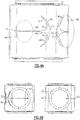
Figure 3 shows thespool 41. The fluid is delivered into the interior as shown by arrow F. It then flows outwardly through a window profile defined bywindow portions - As shown in
Figure 4A , theprofiles circumferential end 70, flow area is small. - In
Figure 4A , this is shown aligned with theopening 44. In the positions shown inFigure 4A , there would be a relatively small amount of fluid being delivered to theheat exchanger 28 compared to the amount delivered from the relatively large portions defined bywings 60 andcentral portion 62, which are communicating with theoutlet 46. - However, as the
spool 41 moves circumferentially, one can appreciate that the size of thewindow 52 aligned with thepassage 46 will move into smaller portions such that it approaches the end 70 (not shown forprofile 52, but it is the same as profile 50). - Thus, as the
control 40 changes the circumferential location of thespool 41, the amount of fluid delivered intolines windows - In the illustrated embodiment, an
end 71 opposite to end 70 is the relatively large volume portion and includes thecentral portion 62 and thewings 60. As shown, angled ends 64 extend from acentral portion 62 into a smallercentral portion 66 and then into a taperingportion 68 that eventually leads to theend 70. - It could be said each of the first and
second windows second valve windows area portions 62 which are circumferentially adjacent to each other andsmaller area portions 68 which are circumferentially spaced from each other. Theenlarged area portion 62 extends between enlarged ends andwings 60 in a direction generally perpendicular to the circumferential direction. -
Figure 4B shows one position, wherein theoutlet 46 is aligned with a greater volume of thewindow 52 than is theoutlet 44 aligned with thewindow 50. As also shown inFigure 4B , there are gaskets or seals 61 sealing off the rest of the window from the flow path into therespective outlets - While a rotary valve is shown, a similar non-linear bypass effect can be achieved in other ways. In one embodiment, the valve may move along an axial direction to achieve non-linear flow.
- As shown in
Figure 5 , due to the non-linear valve, the temperature response seen in the air being cooled is relatively linear with a change in bypass ratio. - This can be explained by reference to
Figures 5 . -
Figure 6 compares a flow split for a linear flow profile with that for a non-linear flow. As can be appreciated in the left-hand graph, a change in the primary flow X moves in a linear manner compared to a change in the secondary or bypass flow Y. - However, as shown on the graph to the right, with a non-linear flow split, the primary flow X and the secondary flow Y change in a non-linear manner.
- As mentioned above, Applicant has recognized that such a change will result in a linear temperature change for the fluid to be cooled.
- Another
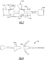
embodiment 100 is shown inFigure 7 . Here, afluid supply 102 is split betweensupplies heat exchanger 28, and a bypass line, as shown inFigure 1 . - An
actuator 108 moves ashaft 110 in a linear direction to move twovalve pistons valve seats - Applicant has also recognized that symmetric windows such as shown in
Figures 3 and4A may not be the most preferred embodiment. - Rather, Applicant has recognized that a linear temperature profile may be best achieved by having different changes in the respective flow rate. As an example,
Figure 8 shows anembodiment 150 wherein awindow 154 supplies fluid to the heat exchanger and anotherwindow 152, supplies fluid to the bypass.Windows - In one example, as the
window 154 begins to be closed, it gains 80% of flow within a first 18% of rotation, in one example. On the other hand, as thewindow 152 moves to close, it gains only 20% of flow over 82% of rotation. Thus, in this example, thewindows - Of course, these numbers are simply examples, The specifics of a particular system will dictate the respect flow rates. Armed with this disclosure, a worker of ordinary skill in this art will be able to recognize how to design the windows to achieve this flow. The profiles of the
valve pistons Figure 7 embodiment can also be modified in view of this concept such that they are not symmetric. - A unique system is disclosed for providing a controlled supply of a cooled fluid. It should be understood that a system would have benefits in many other applications. As only one example, the fluid with the controlled temperature and without the bypass valve might be heated rather than cooled.
- This disclosure provides a temperature response in a first fluid that approaches a linear change, with respect to a modulating valve position for a second fluid. The valve modulates the second fluid saves weight and volume. The valve design has a nonlinear flow split to achieve this feature.
- Although an embodiment of this invention has been disclosed, a worker of ordinary skill in this art would recognize that certain modifications would come within the scope of this invention. For that reason, the following claims should be studied to determine the true scope and content of this invention.
Claims (15)
- A system for changing the temperature of a first fluid to meet a desired temperature comprising:a fluid supply for said first fluid, said fluid supply for said first fluid passing through a heat exchanger (28), and a temperature sensor (36) for said first fluid to sense a temperature of said first fluid downstream of said heat exchanger;a supply for a second fluid to change a temperature of said first fluid, said supply for said second fluid passing through said heat exchanger (28);a valve (30) positioned upstream of said heat exchanger (28) on said supply for said second fluid, and controlling a flow rate of said second fluid diverted into a bypass line (32) compared to a flow rate of said second fluid directed through said heat exchanger (28), with said three-way valve controlled by a control (40) in response to feedback from said temperature sensor (36); andsaid valve (30) changes the respective flow rates delivered into said bypass line (32) and through said heat exchanger (28) in a non-linear manner with a change in valve position.
- The system as set forth in claim 1, wherein said second fluid cools said first fluid, and preferably wherein said first fluid is air and said second fluid is a cooling fluid for air, and more preferably wherein said air is to be delivered into an interior of a manned spacecraft.
- The system as set forth in claims 1 or 2, wherein said valve includes a rotating spool (41) with a first window (50) delivering said second fluid into a first outlet leading to said bypass line and a second window (52) delivering fluid into a line leading to said heat exchanger and said valve (30) changing position in a circumferential direction to achieve said non-linear manner of changing the respective flow rates.
- The system as set forth in claim 3, wherein each of said first and second windows (50, 52) have an enlarged area portion and which change in a non-linear manner when moving in a circumferential direction.
- The system as set forth in claim 3, wherein said first and second windows (50, 52) are also designed to achieve a change in pressure drop as said valve spool (41) rotates to, in turn, keep a total pressure drop across said system between said valve (30) and said heat exchanger (28) that is relatively close to constant as said valve (30) changes the portion of the second fluid passing through said heat exchanger (28).
- The system as set forth in claim 5, wherein said first and second windows (50, 52) are non- symmetric; or wherein said first and second windows (50, 52) are symmetric.
- The system as set forth in claim 3, wherein said first and second windows (50, 52) are non- symmetric.
- The system as set forth in any preceding claim, wherein said valve (30) moves axially, and two valve pistons control the respective flow to said bypass line (32) and to said heat exchanger (28).
- The system as set forth in any preceding claim, wherein fluid passages in said valve leading to said bypass line (32) and said heat exchanger (28) are non-symmetric.
- The system as set forth in any preceding claim, wherein said valve (30) is designed to achieve a change in pressure drop as said valve (30) moves to, in turn, keep a total pressure drop across said system between said valve (30) and said heat exchanger that is relatively close to constant as said valve (30) changes the portion of the second fluid passing through said heat exchanger (28).
- A manned spaceship including a system for supplying air into an interior of said spacecraft comprising:a fluid supply for said air, said fluid supply for said air passing through a heat exchanger (28), and a temperature sensor (36) for said air to sense a temperature of said air downstream of said heat exchanger (28);a supply for a second fluid to change a temperature of said air, said supply for said second fluid passing through said heat exchanger (28);a valve (30) positioned upstream of said heat exchanger (28) on said supply for said second fluid, and controlling a flow rate of said second fluid diverted into a bypass line (32) compared to a flow rate of said second fluid directed through said heat exchanger (28), with said valve (30) controlled by a control in response to feedback from said temperature sensor (36); andsaid three-way valve (30) changes the respective volumes delivered into said bypass line (32) and through said heat exchanger (28) in a non-linear manner with a change in valve position.
- The manned spaceship as set forth in claim 11, wherein said fluid passages in said valve are non-symmetric.
- The manned spaceship as set forth in claims 11 or 12, wherein said valve (30) includes a rotating spool (41), and preferably wherein fluid passages on said spool (41) leading to said bypass line (32) and said heat exchanger (28) are non-symmetric.
- The manned spaceship as set forth in claims 11, 12, or 13, wherein said valve (30) moves axially, and two valve pistons control the respective flow to said bypass line (32) and to said heat exchanger (28); and or wherein fluid passages in said valve (30) leading to said bypass line (32) and said heat exchanger (28) are non-symmetric.
- The manned spaceship as set forth in any of claims 11-14, wherein said valve (30) is designed to achieve a change in pressure drop as said valve (30) moves to, in turn, keep a total pressure drop across said system between said valve (30) and said heat exchanger (28) that is relatively close to constant as said valve (30) changes the portion of the second fluid passing through said heat exchanger (28).
Applications Claiming Priority (1)
| Application Number | Priority Date | Filing Date | Title |
|---|---|---|---|
| US15/665,654 US20190041145A1 (en) | 2017-08-01 | 2017-08-01 | Three-way modulating valve for temperature control |
Publications (3)
| Publication Number | Publication Date |
|---|---|
| EP3438780A2 true EP3438780A2 (en) | 2019-02-06 |
| EP3438780A3 EP3438780A3 (en) | 2019-06-26 |
| EP3438780B1 EP3438780B1 (en) | 2021-01-06 |
Family
ID=63142974
Family Applications (1)
| Application Number | Title | Priority Date | Filing Date |
|---|---|---|---|
| EP18186848.0A Active EP3438780B1 (en) | 2017-08-01 | 2018-08-01 | Three-way modulating valve for temperature control |
Country Status (2)
| Country | Link |
|---|---|
| US (2) | US20190041145A1 (en) |
| EP (1) | EP3438780B1 (en) |
Family Cites Families (34)
| Publication number | Priority date | Publication date | Assignee | Title |
|---|---|---|---|---|
| US1622406A (en) * | 1925-11-24 | 1927-03-29 | Wilhjelm Christian | Valve |
| US3542338A (en) * | 1968-07-29 | 1970-11-24 | Domer Scaramucci | Throttling valve |
| DE2413420A1 (en) * | 1974-03-20 | 1975-10-02 | Klaus Dipl Ing Scheuermann | MIXING BATTERY SYSTEM |
| DE2414758B2 (en) * | 1974-03-27 | 1976-04-15 | Varta Batterie Ag, 3000 Hannover | ELECTROLYTE COOLING DEVICE FOR ACCUMULATOR BATTERIES CONSISTING OF MULTIPLE CELLS |
| SE414960B (en) * | 1978-02-09 | 1980-08-25 | Tour & Andersson Ab | Three-way valve with enlarged control area |
| DE3125459A1 (en) * | 1981-06-29 | 1983-01-20 | Centra-Bürkle GmbH & Co, 7036 Schönaich | Mixing or distributing valve |
| US4786294A (en) * | 1987-12-21 | 1988-11-22 | Allied-Signal Inc. | Integrated gas purification and thermal conditioning system utilizing molecular sieve adsorption |
| FI81895C (en) * | 1988-12-30 | 1990-12-10 | Neles Oy | REGLERVENTIL. |
| US5074522A (en) * | 1991-03-11 | 1991-12-24 | Worcester Controls Corporation | Ball valve having improved inherent rangeability |
| US5957377A (en) * | 1994-06-17 | 1999-09-28 | Nippondenso Co., Ltd. | Flow control valve and hot-water type heater apparatus employing the same |
| JP3580034B2 (en) * | 1996-07-19 | 2004-10-20 | 株式会社デンソー | Hot water heating system |
| US6109591A (en) * | 1996-10-25 | 2000-08-29 | Tuttle; James D. | Wide range proportional flow control valve |
| JP3780600B2 (en) | 1997-02-10 | 2006-05-31 | 株式会社デンソー | Hot water heater |
| JP3911811B2 (en) * | 1997-06-05 | 2007-05-09 | 株式会社デンソー | Hot water heater |
| US6039304A (en) * | 1998-05-26 | 2000-03-21 | Belimo Air Control (Usa) Inc. | Ball valve with modified characteristics |
| US7147071B2 (en) * | 2004-02-04 | 2006-12-12 | Battelle Energy Alliance, Llc | Thermal management systems and methods |
| WO2000037838A1 (en) * | 1998-12-23 | 2000-06-29 | BELIMO AIRCONTROLs (USA), INC. | Control valve with modified characteristics |
| US6257003B1 (en) * | 2000-08-04 | 2001-07-10 | Hamilton Sundstrand Corporation | Environmental control system utilizing two air cycle machines |
| US6415595B1 (en) * | 2000-08-22 | 2002-07-09 | Hamilton Sundstrand Corporation | Integrated thermal management and coolant system for an aircraft |
| FR2844571B1 (en) * | 2002-09-18 | 2008-02-29 | Valeo Thermique Moteur Sa | CONTROL VALVE FOR A FLUID CIRCUIT AND CIRCUIT COMPRISING SAID VALVE |
| US7111643B2 (en) * | 2005-01-26 | 2006-09-26 | Invensys Building Systems, Inc. | Flow characterization in a flowpath |
| KR101180041B1 (en) * | 2006-10-31 | 2012-09-05 | 한라공조주식회사 | Heater Core And Air conditioner for an Automobile equipped with same |
| JP5496212B2 (en) * | 2008-10-02 | 2014-05-21 | イベリカ デル エスパシオ、ソシエダッド アノニマ | A thermal module for controlling the heat load from a heat source and a spacecraft modular thermal platform for a spacecraft |
| US8375990B2 (en) * | 2010-02-24 | 2013-02-19 | Masco Corporation Of Indiana | Mixing valve including dual flow control |
| US8899009B2 (en) * | 2011-01-05 | 2014-12-02 | Hamilton Sundstrand Corporation | Fuel anti-icing and APU compartment drain combination |
| CN202228755U (en) | 2011-08-22 | 2012-05-23 | 北京市自动化系统成套工程公司 | Valve core of thermal special multifunctional three-way control valve |
| DE102011118873A1 (en) * | 2011-11-18 | 2013-05-23 | Airbus Operations Gmbh | Vehicle with a cooling system for cooling and method for cooling in a vehicle |
| CN106949695A (en) * | 2012-03-22 | 2017-07-14 | B/E航空公司 | Vehicles refrigeration plant with steam circulation |
| US9472819B2 (en) * | 2012-04-27 | 2016-10-18 | Hamilton Sundstrand Corporation | Warming feature for aircraft fuel cells |
| CH708205A1 (en) * | 2013-06-12 | 2014-12-15 | Belimo Holding Ag | Control tap. |
| JP6415943B2 (en) | 2014-11-21 | 2018-10-31 | 三菱重工サーマルシステムズ株式会社 | Heat pump air conditioning system for vehicles |
| FR3040148A1 (en) * | 2015-08-20 | 2017-02-24 | Hutchinson | CIRCUIT AND METHOD FOR COOLING ON A VEHICLE |
| DE102015016785A1 (en) * | 2015-10-22 | 2017-04-27 | Voss Automotive Gmbh | Mass flow control unit and coolant system with at least three coolant lines and with at least one such mass flow control unit |
| US9643134B1 (en) * | 2016-07-12 | 2017-05-09 | Mazzei Injector Company, Llc | Proportionate automated blending system for aqueous mixtures |
-
2017
- 2017-08-01 US US15/665,654 patent/US20190041145A1/en not_active Abandoned
-
2018
- 2018-08-01 EP EP18186848.0A patent/EP3438780B1/en active Active
-
2020
- 2020-07-21 US US16/934,437 patent/US11519680B2/en active Active
Non-Patent Citations (1)
| Title |
|---|
| None |
Also Published As
| Publication number | Publication date |
|---|---|
| US20190041145A1 (en) | 2019-02-07 |
| EP3438780B1 (en) | 2021-01-06 |
| US11519680B2 (en) | 2022-12-06 |
| EP3438780A3 (en) | 2019-06-26 |
| US20200348092A1 (en) | 2020-11-05 |
Similar Documents
| Publication | Publication Date | Title |
|---|---|---|
| US11028931B2 (en) | Flow control valve and hydronic system | |
| US5899805A (en) | Distribution damper valve | |
| KR102069957B1 (en) | Method for controlling an oil-injected compressor device | |
| US11098938B2 (en) | Heat pump temperature control | |
| EP3246781B1 (en) | Pressure regulation valve | |
| US6179570B1 (en) | Variable pump control for hydraulic fan drive | |
| JP6723270B2 (en) | valve | |
| US11747098B2 (en) | Temperature control apparatus | |
| US9933085B2 (en) | Integrating valve with soft start | |
| EP2956697B1 (en) | Modulating balance ported three way valve | |
| US20230407976A1 (en) | Axial three-way modulating valve | |
| US20150292525A1 (en) | Servo Valve | |
| EP3513266B1 (en) | Flowrate stabilising monoblock cartridge for hydraulic valves | |
| CN101600916A (en) | Air Conditioning Control Algorithm Using Air and Fluid Inputs | |
| US6634322B2 (en) | Heat exchanger tempering valve | |
| EP3333528B1 (en) | Heat exchanger with sliding aperture valve | |
| US11519680B2 (en) | Three-way modulating valve for temperature control | |
| EP3045792A1 (en) | Pneumatic actuator low flow servo valve | |
| US7909262B2 (en) | Pressure relieved thermal regulator for air conditioning application | |
| CN119933972A (en) | Method for operating axial piston machines taking into account the zero condition | |
| US11359822B2 (en) | Circulation pump assembly | |
| US20130118624A1 (en) | Sealed flapper diverter valve | |
| EP4098912B1 (en) | Control valve for heating and/or cooling system manifold and floor heating system | |
| EP3395688B1 (en) | Configurable high rate closed loop smart valve control | |
| EP4666146A1 (en) | Control valve for selectively controlling a fluid flow |
Legal Events
| Date | Code | Title | Description |
|---|---|---|---|
| PUAI | Public reference made under article 153(3) epc to a published international application that has entered the european phase |
Free format text: ORIGINAL CODE: 0009012 |
|
| STAA | Information on the status of an ep patent application or granted ep patent |
Free format text: STATUS: THE APPLICATION HAS BEEN PUBLISHED |
|
| AK | Designated contracting states |
Kind code of ref document: A2 Designated state(s): AL AT BE BG CH CY CZ DE DK EE ES FI FR GB GR HR HU IE IS IT LI LT LU LV MC MK MT NL NO PL PT RO RS SE SI SK SM TR |
|
| AX | Request for extension of the european patent |
Extension state: BA ME |
|
| PUAL | Search report despatched |
Free format text: ORIGINAL CODE: 0009013 |
|
| AK | Designated contracting states |
Kind code of ref document: A3 Designated state(s): AL AT BE BG CH CY CZ DE DK EE ES FI FR GB GR HR HU IE IS IT LI LT LU LV MC MK MT NL NO PL PT RO RS SE SI SK SM TR |
|
| AX | Request for extension of the european patent |
Extension state: BA ME |
|
| RIC1 | Information provided on ipc code assigned before grant |
Ipc: F16K 5/12 20060101ALI20190520BHEP Ipc: F16K 1/54 20060101ALI20190520BHEP Ipc: B64D 13/08 20060101ALI20190520BHEP Ipc: F28F 27/00 20060101ALI20190520BHEP Ipc: G05D 23/19 20060101AFI20190520BHEP Ipc: F16K 11/044 20060101ALI20190520BHEP Ipc: F01P 7/14 20060101ALI20190520BHEP Ipc: F16K 11/085 20060101ALI20190520BHEP |
|
| STAA | Information on the status of an ep patent application or granted ep patent |
Free format text: STATUS: REQUEST FOR EXAMINATION WAS MADE |
|
| 17P | Request for examination filed |
Effective date: 20191220 |
|
| RBV | Designated contracting states (corrected) |
Designated state(s): AL AT BE BG CH CY CZ DE DK EE ES FI FR GB GR HR HU IE IS IT LI LT LU LV MC MK MT NL NO PL PT RO RS SE SI SK SM TR |
|
| GRAP | Despatch of communication of intention to grant a patent |
Free format text: ORIGINAL CODE: EPIDOSNIGR1 |
|
| GRAJ | Information related to disapproval of communication of intention to grant by the applicant or resumption of examination proceedings by the epo deleted |
Free format text: ORIGINAL CODE: EPIDOSDIGR1 |
|
| GRAP | Despatch of communication of intention to grant a patent |
Free format text: ORIGINAL CODE: EPIDOSNIGR1 |
|
| RIC1 | Information provided on ipc code assigned before grant |
Ipc: G05D 23/19 20060101AFI20200511BHEP Ipc: B64D 13/08 20060101ALI20200511BHEP Ipc: F01P 7/14 20060101ALI20200511BHEP Ipc: F16K 11/085 20060101ALI20200511BHEP Ipc: F28F 27/00 20060101ALI20200511BHEP Ipc: F16K 5/12 20060101ALI20200511BHEP Ipc: F16K 11/044 20060101ALI20200511BHEP Ipc: F16K 1/54 20060101ALI20200511BHEP |
|
| STAA | Information on the status of an ep patent application or granted ep patent |
Free format text: STATUS: GRANT OF PATENT IS INTENDED |
|
| INTG | Intention to grant announced |
Effective date: 20200617 |
|
| INTG | Intention to grant announced |
Effective date: 20200617 |
|
| GRAJ | Information related to disapproval of communication of intention to grant by the applicant or resumption of examination proceedings by the epo deleted |
Free format text: ORIGINAL CODE: EPIDOSDIGR1 |
|
| GRAP | Despatch of communication of intention to grant a patent |
Free format text: ORIGINAL CODE: EPIDOSNIGR1 |
|
| INTG | Intention to grant announced |
Effective date: 20200731 |
|
| GRAS | Grant fee paid |
Free format text: ORIGINAL CODE: EPIDOSNIGR3 |
|
| GRAA | (expected) grant |
Free format text: ORIGINAL CODE: 0009210 |
|
| STAA | Information on the status of an ep patent application or granted ep patent |
Free format text: STATUS: THE PATENT HAS BEEN GRANTED |
|
| AK | Designated contracting states |
Kind code of ref document: B1 Designated state(s): AL AT BE BG CH CY CZ DE DK EE ES FI FR GB GR HR HU IE IS IT LI LT LU LV MC MK MT NL NO PL PT RO RS SE SI SK SM TR |
|
| REG | Reference to a national code |
Ref country code: GB Ref legal event code: FG4D |
|
| REG | Reference to a national code |
Ref country code: AT Ref legal event code: REF Ref document number: 1353054 Country of ref document: AT Kind code of ref document: T Effective date: 20210115 Ref country code: CH Ref legal event code: EP |
|
| REG | Reference to a national code |
Ref country code: DE Ref legal event code: R096 Ref document number: 602018011511 Country of ref document: DE |
|
| REG | Reference to a national code |
Ref country code: IE Ref legal event code: FG4D |
|
| REG | Reference to a national code |
Ref country code: NL Ref legal event code: MP Effective date: 20210106 |
|
| REG | Reference to a national code |
Ref country code: AT Ref legal event code: MK05 Ref document number: 1353054 Country of ref document: AT Kind code of ref document: T Effective date: 20210106 |
|
| REG | Reference to a national code |
Ref country code: LT Ref legal event code: MG9D |
|
| PG25 | Lapsed in a contracting state [announced via postgrant information from national office to epo] |
Ref country code: LT Free format text: LAPSE BECAUSE OF FAILURE TO SUBMIT A TRANSLATION OF THE DESCRIPTION OR TO PAY THE FEE WITHIN THE PRESCRIBED TIME-LIMIT Effective date: 20210106 Ref country code: PT Free format text: LAPSE BECAUSE OF FAILURE TO SUBMIT A TRANSLATION OF THE DESCRIPTION OR TO PAY THE FEE WITHIN THE PRESCRIBED TIME-LIMIT Effective date: 20210506 Ref country code: NO Free format text: LAPSE BECAUSE OF FAILURE TO SUBMIT A TRANSLATION OF THE DESCRIPTION OR TO PAY THE FEE WITHIN THE PRESCRIBED TIME-LIMIT Effective date: 20210406 Ref country code: BG Free format text: LAPSE BECAUSE OF FAILURE TO SUBMIT A TRANSLATION OF THE DESCRIPTION OR TO PAY THE FEE WITHIN THE PRESCRIBED TIME-LIMIT Effective date: 20210406 Ref country code: GR Free format text: LAPSE BECAUSE OF FAILURE TO SUBMIT A TRANSLATION OF THE DESCRIPTION OR TO PAY THE FEE WITHIN THE PRESCRIBED TIME-LIMIT Effective date: 20210407 Ref country code: FI Free format text: LAPSE BECAUSE OF FAILURE TO SUBMIT A TRANSLATION OF THE DESCRIPTION OR TO PAY THE FEE WITHIN THE PRESCRIBED TIME-LIMIT Effective date: 20210106 Ref country code: HR Free format text: LAPSE BECAUSE OF FAILURE TO SUBMIT A TRANSLATION OF THE DESCRIPTION OR TO PAY THE FEE WITHIN THE PRESCRIBED TIME-LIMIT Effective date: 20210106 |
|
| PG25 | Lapsed in a contracting state [announced via postgrant information from national office to epo] |
Ref country code: AT Free format text: LAPSE BECAUSE OF FAILURE TO SUBMIT A TRANSLATION OF THE DESCRIPTION OR TO PAY THE FEE WITHIN THE PRESCRIBED TIME-LIMIT Effective date: 20210106 Ref country code: LV Free format text: LAPSE BECAUSE OF FAILURE TO SUBMIT A TRANSLATION OF THE DESCRIPTION OR TO PAY THE FEE WITHIN THE PRESCRIBED TIME-LIMIT Effective date: 20210106 Ref country code: PL Free format text: LAPSE BECAUSE OF FAILURE TO SUBMIT A TRANSLATION OF THE DESCRIPTION OR TO PAY THE FEE WITHIN THE PRESCRIBED TIME-LIMIT Effective date: 20210106 Ref country code: RS Free format text: LAPSE BECAUSE OF FAILURE TO SUBMIT A TRANSLATION OF THE DESCRIPTION OR TO PAY THE FEE WITHIN THE PRESCRIBED TIME-LIMIT Effective date: 20210106 Ref country code: SE Free format text: LAPSE BECAUSE OF FAILURE TO SUBMIT A TRANSLATION OF THE DESCRIPTION OR TO PAY THE FEE WITHIN THE PRESCRIBED TIME-LIMIT Effective date: 20210106 |
|
| PG25 | Lapsed in a contracting state [announced via postgrant information from national office to epo] |
Ref country code: IS Free format text: LAPSE BECAUSE OF FAILURE TO SUBMIT A TRANSLATION OF THE DESCRIPTION OR TO PAY THE FEE WITHIN THE PRESCRIBED TIME-LIMIT Effective date: 20210506 |
|
| REG | Reference to a national code |
Ref country code: DE Ref legal event code: R097 Ref document number: 602018011511 Country of ref document: DE |
|
| PG25 | Lapsed in a contracting state [announced via postgrant information from national office to epo] |
Ref country code: SM Free format text: LAPSE BECAUSE OF FAILURE TO SUBMIT A TRANSLATION OF THE DESCRIPTION OR TO PAY THE FEE WITHIN THE PRESCRIBED TIME-LIMIT Effective date: 20210106 Ref country code: CZ Free format text: LAPSE BECAUSE OF FAILURE TO SUBMIT A TRANSLATION OF THE DESCRIPTION OR TO PAY THE FEE WITHIN THE PRESCRIBED TIME-LIMIT Effective date: 20210106 Ref country code: EE Free format text: LAPSE BECAUSE OF FAILURE TO SUBMIT A TRANSLATION OF THE DESCRIPTION OR TO PAY THE FEE WITHIN THE PRESCRIBED TIME-LIMIT Effective date: 20210106 |
|
| PLBE | No opposition filed within time limit |
Free format text: ORIGINAL CODE: 0009261 |
|
| STAA | Information on the status of an ep patent application or granted ep patent |
Free format text: STATUS: NO OPPOSITION FILED WITHIN TIME LIMIT |
|
| PG25 | Lapsed in a contracting state [announced via postgrant information from national office to epo] |
Ref country code: RO Free format text: LAPSE BECAUSE OF FAILURE TO SUBMIT A TRANSLATION OF THE DESCRIPTION OR TO PAY THE FEE WITHIN THE PRESCRIBED TIME-LIMIT Effective date: 20210106 Ref country code: SK Free format text: LAPSE BECAUSE OF FAILURE TO SUBMIT A TRANSLATION OF THE DESCRIPTION OR TO PAY THE FEE WITHIN THE PRESCRIBED TIME-LIMIT Effective date: 20210106 Ref country code: DK Free format text: LAPSE BECAUSE OF FAILURE TO SUBMIT A TRANSLATION OF THE DESCRIPTION OR TO PAY THE FEE WITHIN THE PRESCRIBED TIME-LIMIT Effective date: 20210106 |
|
| 26N | No opposition filed |
Effective date: 20211007 |
|
| PG25 | Lapsed in a contracting state [announced via postgrant information from national office to epo] |
Ref country code: ES Free format text: LAPSE BECAUSE OF FAILURE TO SUBMIT A TRANSLATION OF THE DESCRIPTION OR TO PAY THE FEE WITHIN THE PRESCRIBED TIME-LIMIT Effective date: 20210106 Ref country code: AL Free format text: LAPSE BECAUSE OF FAILURE TO SUBMIT A TRANSLATION OF THE DESCRIPTION OR TO PAY THE FEE WITHIN THE PRESCRIBED TIME-LIMIT Effective date: 20210106 |
|
| PG25 | Lapsed in a contracting state [announced via postgrant information from national office to epo] |
Ref country code: SI Free format text: LAPSE BECAUSE OF FAILURE TO SUBMIT A TRANSLATION OF THE DESCRIPTION OR TO PAY THE FEE WITHIN THE PRESCRIBED TIME-LIMIT Effective date: 20210106 |
|
| REG | Reference to a national code |
Ref country code: CH Ref legal event code: PL |
|
| PG25 | Lapsed in a contracting state [announced via postgrant information from national office to epo] |
Ref country code: MC Free format text: LAPSE BECAUSE OF FAILURE TO SUBMIT A TRANSLATION OF THE DESCRIPTION OR TO PAY THE FEE WITHIN THE PRESCRIBED TIME-LIMIT Effective date: 20210106 |
|
| REG | Reference to a national code |
Ref country code: BE Ref legal event code: MM Effective date: 20210831 |
|
| PG25 | Lapsed in a contracting state [announced via postgrant information from national office to epo] |
Ref country code: LI Free format text: LAPSE BECAUSE OF NON-PAYMENT OF DUE FEES Effective date: 20210831 Ref country code: CH Free format text: LAPSE BECAUSE OF NON-PAYMENT OF DUE FEES Effective date: 20210831 |
|
| PG25 | Lapsed in a contracting state [announced via postgrant information from national office to epo] |
Ref country code: IS Free format text: LAPSE BECAUSE OF FAILURE TO SUBMIT A TRANSLATION OF THE DESCRIPTION OR TO PAY THE FEE WITHIN THE PRESCRIBED TIME-LIMIT Effective date: 20210506 Ref country code: LU Free format text: LAPSE BECAUSE OF NON-PAYMENT OF DUE FEES Effective date: 20210801 |
|
| PG25 | Lapsed in a contracting state [announced via postgrant information from national office to epo] |
Ref country code: IE Free format text: LAPSE BECAUSE OF NON-PAYMENT OF DUE FEES Effective date: 20210801 Ref country code: FR Free format text: LAPSE BECAUSE OF NON-PAYMENT OF DUE FEES Effective date: 20210831 Ref country code: BE Free format text: LAPSE BECAUSE OF NON-PAYMENT OF DUE FEES Effective date: 20210831 |
|
| P01 | Opt-out of the competence of the unified patent court (upc) registered |
Effective date: 20230522 |
|
| PG25 | Lapsed in a contracting state [announced via postgrant information from national office to epo] |
Ref country code: NL Free format text: LAPSE BECAUSE OF NON-PAYMENT OF DUE FEES Effective date: 20210206 Ref country code: CY Free format text: LAPSE BECAUSE OF FAILURE TO SUBMIT A TRANSLATION OF THE DESCRIPTION OR TO PAY THE FEE WITHIN THE PRESCRIBED TIME-LIMIT Effective date: 20210106 |
|
| PG25 | Lapsed in a contracting state [announced via postgrant information from national office to epo] |
Ref country code: HU Free format text: LAPSE BECAUSE OF FAILURE TO SUBMIT A TRANSLATION OF THE DESCRIPTION OR TO PAY THE FEE WITHIN THE PRESCRIBED TIME-LIMIT; INVALID AB INITIO Effective date: 20180801 |
|
| PG25 | Lapsed in a contracting state [announced via postgrant information from national office to epo] |
Ref country code: MK Free format text: LAPSE BECAUSE OF FAILURE TO SUBMIT A TRANSLATION OF THE DESCRIPTION OR TO PAY THE FEE WITHIN THE PRESCRIBED TIME-LIMIT Effective date: 20210106 |
|
| PG25 | Lapsed in a contracting state [announced via postgrant information from national office to epo] |
Ref country code: TR Free format text: LAPSE BECAUSE OF FAILURE TO SUBMIT A TRANSLATION OF THE DESCRIPTION OR TO PAY THE FEE WITHIN THE PRESCRIBED TIME-LIMIT Effective date: 20210106 |
|
| PG25 | Lapsed in a contracting state [announced via postgrant information from national office to epo] |
Ref country code: MT Free format text: LAPSE BECAUSE OF FAILURE TO SUBMIT A TRANSLATION OF THE DESCRIPTION OR TO PAY THE FEE WITHIN THE PRESCRIBED TIME-LIMIT Effective date: 20210106 |
|
| PGFP | Annual fee paid to national office [announced via postgrant information from national office to epo] |
Ref country code: DE Payment date: 20250724 Year of fee payment: 8 |
|
| PGFP | Annual fee paid to national office [announced via postgrant information from national office to epo] |
Ref country code: IT Payment date: 20250723 Year of fee payment: 8 |
|
| PGFP | Annual fee paid to national office [announced via postgrant information from national office to epo] |
Ref country code: GB Payment date: 20250724 Year of fee payment: 8 |