EP3438718A1 - Lens unit - Google Patents
Lens unit Download PDFInfo
- Publication number
- EP3438718A1 EP3438718A1 EP17773510.7A EP17773510A EP3438718A1 EP 3438718 A1 EP3438718 A1 EP 3438718A1 EP 17773510 A EP17773510 A EP 17773510A EP 3438718 A1 EP3438718 A1 EP 3438718A1
- Authority
- EP
- European Patent Office
- Prior art keywords
- inner peripheral
- peripheral face
- lens
- shaped portion
- circular shaped
- Prior art date
- Legal status (The legal status is an assumption and is not a legal conclusion. Google has not performed a legal analysis and makes no representation as to the accuracy of the status listed.)
- Withdrawn
Links
Images



Classifications
-
- G—PHYSICS
- G02—OPTICS
- G02B—OPTICAL ELEMENTS, SYSTEMS OR APPARATUS
- G02B7/00—Mountings, adjusting means, or light-tight connections, for optical elements
- G02B7/02—Mountings, adjusting means, or light-tight connections, for optical elements for lenses
-
- G—PHYSICS
- G03—PHOTOGRAPHY; CINEMATOGRAPHY; ANALOGOUS TECHNIQUES USING WAVES OTHER THAN OPTICAL WAVES; ELECTROGRAPHY; HOLOGRAPHY
- G03B—APPARATUS OR ARRANGEMENTS FOR TAKING PHOTOGRAPHS OR FOR PROJECTING OR VIEWING THEM; APPARATUS OR ARRANGEMENTS EMPLOYING ANALOGOUS TECHNIQUES USING WAVES OTHER THAN OPTICAL WAVES; ACCESSORIES THEREFOR
- G03B15/00—Special procedures for taking photographs; Apparatus therefor
Definitions
- the present disclosure relates to a lens unit.
- contact portions between the second circular shaped portion and the second inner peripheral face are point contacts when viewed from the optical axis direction due to the second inner peripheral face having a polygonal profile.
- the resistance is reduced during assembly compared to structures where the second circular shaped portion is received with a curved face extending around the entire periphery and there is face-to-face contact therebetween. This enables a fitting length to be lengthened while still maintaining ease of assembly.
- a polygonal profile is broadly defined and includes any structure in which each of the sides of a polygonal profile is connected by a corner or by a circular arc. There is also no limitation to structures in which faces forming each side are flat faces.
- the second inner peripheral face may include curved faces formed to link adjacent of the flat faces together.
- the contact surface area with the second inner peripheral face can be made larger compared to configurations in which the second circular shaped portion is received by a point.
- a deterioration in optical characteristics, resulting from a misalignment in optical axis arising from distortion at the radial direction outside of the lens may be suppressed from occurring.
- the first circular shaped portion and the first inner peripheral face may contact each other at three or more portions in a circumferential direction.
- the positional precision of the lens is easily secured, compared to structures in which the first circular shaped portion contacts the first inner peripheral face over an entire region in the circumferential direction.
- the contact portions between the first circular shaped portion and the first inner peripheral face are point contacts.
- the lens unit according to the sixth aspect accordingly has reduced resistance during assembly compared to structures in which the first circular shaped portion is received by a curved face with face-to-face contact therebetween. This enables the fitting length to be lengthened while still maintaining ease of assembly.
- the lens unit according to the seventh aspect of the present disclosure stress that would act on the first inner peripheral face as in a structure in which adjacent flat faces were connected together by angled corners can be suppressed from being concentrated at angled corners.
- the lens unit according to the seventh aspect is capable of dispersing stress acting on the first inner peripheral face.
- the second inner peripheral face is positioned further to the radial direction outside than the first inner peripheral face, this would be an under-cut when removing the mold component (core pin) for molding this portion, resulting in resistance to demolding resulting in the component not being removable from the mold.
- positioning the first inner peripheral face further to the radial direction outside than the second inner peripheral face enables a situation to be suppressed from arising in which the mold component is not removable.
- deterioration in performance may be reduced even for a lens unit employed in an environment in which there is a possibility of being exposed to high temperatures and it is difficult to maintain image forming performance, such as in a surveillance camera or an onboard camera.
- the second circular shaped portion 16 is positioned on the imaging side of the lens 12 and is integrally formed to the first circular shaped portion 14.
- the second circular shaped portion 16 includes a second lens section 16A including an optical surface, and a second peripheral edge section 16B configuring a section at an outer periphery of the second lens section 16A. Further, a face on the imaging side of the second circular shaped portion 16 is curved so as to be convex on the imaging side.
- the lens-barrel 18 is open at both optical axis direction ends thereof, is formed in a substantially circular cylinder shape, and is formed by resin molding. Further, a holding portion (not illustrated in the drawings) is provided at the imaging side end of the lens-barrel 18. A through hole that functions as an optical aperture is formed in this holding portion. Furthermore, a crimped portion (not illustrated in the drawings) is formed by heat crimping the object side end of the lens-barrel 18. Components of the optical system are suppressed from coming out from the lens-barrel 18 by this crimped portion.
- resins that may be employed therefor include at least one type of resin selected from the group consisting of a polyamide, a polyacetal, a polycarbonate, a polyphenylene ether, a polybutylene terephthalate, a polyethylene terephthalate, a polyethylene, a syndiotactic polystyrene, a polysulfone, a polyethersulfphone, a polyphenylene sulfide, a polyarylate, a polyamide-imide, a polyetherimide, a polyetheretherketone, an acrylonitrile butadiene styrene, a polyolefin, and a modified polymer of any of these resins.
- the resin may also be a polymer alloy containing at least one resin selected from this group. Fibers that may be employed include glass fibers and carbon fibers, and a fiber reinforced plastic including an inorganic filler or the like may be employed.
- a step 24 is formed to the inner peripheral face of the lens-barrel 18 at a boundary portion between the first step portion 20 and the second step portion 22.
- the step 24 is inclined toward the radial direction inside on progression from the object side toward the imaging side. Accordingly, the first inner peripheral face 20A is positioned further to the radial direction outside than the second inner peripheral face 22A.
- the lens 12 can be suppressed from tilting compared to structures in which a lens only makes contact with the inner peripheral face of the lens-barrel 18 at a single location when viewed from the radial direction of the lens-barrel 18.
- a structure of a comparative example in which the lens 12 only makes contacts at the second inner peripheral face 22A there is a gap between the first circular shaped portion 14 of the lens 12 and the first inner peripheral face 20A of the lens-barrel 18.
- the object side of the lens 12 is accordingly not supported by the lens-barrel 18, and so tilting readily occurs.
- the first inner peripheral face 20A is positioned further to the radial direction outside than the second inner peripheral face 22A.
- the present exemplary embodiment enables easier processing for the lens-barrel 18 than structures in which the first inner peripheral face 20A and the second inner peripheral face 22A are formed at the same radial direction positions to each other, namely structures in which the first inner peripheral face 20A and the second inner peripheral face 22A have the same diameter as each other.
- the first circular shaped portion 44 of the lens 42 fits together with the first inner peripheral face 47A of the lens-barrel 48
- the second circular shaped portion 46 of the lens 42 fits together with the second inner peripheral face 49A of the lens-barrel 48.
- the lens 42 makes contact with the inner peripheral face of the lens-barrel 48 at plural locations when viewed from a direction orthogonal to the optical axis direction (a radial direction of the lens-barrel 48).
- the lens 42 when viewed from the radial direction of the lens-barrel 48, there is no need to lengthen the length along the optical axis direction of the respective contact portions of the first circular shaped portion 44 and the second circular shaped portion 46.
- the lens 42 can be suppressed from tilting even though the contact portions P1 and the contact portions P2 are comparatively short.
- the lens 42 can be suppressed from becoming difficult to insert when assembling the lens 42 to the lens-barrel 48, enabling ease of assembly to be secured.
- a lens-barrel 18 configuring a lens unit 50 according to a third modified example is configured including a first step portion 52 and a second step portion 22.
- the second step portion 22 is configured similarly to in the exemplary embodiment, and a second circular shaped portion 16 of the lens 12 is fitted together with a second inner peripheral face 22A of the second step portion 22.
- the lens 12 can be suppressed from tilting while still securing an ease of assembly similar to that of the exemplary embodiment above, even though this is a case in which the second inner peripheral face 62A is configured by the curved faces 62AS instead of by flat faces.
- the indentation portions 72AN are formed by hollowing locations between adjacent flat faces toward the radial direction outside.
- the first inner peripheral face of the lens-barrel 62 is configured similarly to that of the exemplary embodiment above (see Fig. 3 ).
- the lens 12 can be suppressed from tilting while still securing an ease of assembly similar to that of the exemplary embodiment above.
- the contact surface area with the second inner peripheral face 72A can be made larger compared to configurations in which the second circular shaped portion 16 is received at points.
- the overall optical axis direction of the lens 12 can be suppressed from tilting.
Landscapes
- Physics & Mathematics (AREA)
- General Physics & Mathematics (AREA)
- Optics & Photonics (AREA)
- Lens Barrels (AREA)
Abstract
Description
- The present disclosure relates to a lens unit.
- Lens units having plural lenses made from plastic (resin) inserted into a lens-barrel made from plastic (resin) and having a polygonal shaped inner peripheral face are disclosed in Japanese Patent Publication Nos.
4847020 5406165 JP-A) Nos. 2011-002576 2009-216774 - Adopting a polygonal shaped inner peripheral face for a lens-barrel, such as in Japanese Patent Publication Nos.
4847020 5406165 JP-A Nos. 2011-002576 2009-216774 - The present disclosure provides a lens unit that may suppress lenses from tilting while securing ease of assembly in a configuration having a lens-barrel formed from a resin.
- A first aspect of the present disclosure is a lens unit including: a lens including a first circular shaped portion and a second circular shaped portion arranged in a row along an optical axis direction; and a lens-barrel formed of a resin and formed in a tubular shape, the lens-barrel including: a first inner peripheral face to which the first circular shaped portion is fitted, and a second inner peripheral face to which the second circular shaped portion is fitted and is positioned separated in the optical axis direction from a fitting section where the first circular shaped portion and the first inner peripheral face are fitted, the second circular shaped portion contacts with the second inner peripheral face at three or more portions in a circumferential direction.
- In the lens unit according to the first aspect of the present disclosure, the first circular shaped portion of the lens fits together with the first inner peripheral face of the lens-barrel. The second circular shaped portion of the lens fits together with the second inner peripheral face of the lens-barrel at a position separated in the optical axis direction from the fitting section where the first circular shaped portion and the first inner peripheral face fit together. Thus in the lens unit according to the first aspect, the lens contacts the inner peripheral face of the lens-barrel at plural locations when viewed from a direction orthogonal to the optical axis direction (a radial direction of the lens-barrel). This enables the lens to be suppressed from tilting compared to structures in which the lens only contacts an inner peripheral face of the lens-barrel at a single location when viewed from the radial direction of the lens-barrel.
- Moreover, in the lens unit according to the first aspect, the second circular shaped portion makes contact with the second inner peripheral face at three or more locations in the circumferential direction and so positional precision of the lens is easily secured. This means that there is no need to lengthen the fitting length for each of the first circular shaped portion and the second circular shaped portion due to performing positioning of the lens at the second inner peripheral face. As a result, in the lens unit according to the first aspect, the lens may be suppressed from becoming difficult to insert into the lens-barrel when assembling the lens, enabling ease of assembly to be secured.
- In a lens unit according to a second aspect of the present disclosure, in the lens unit according to the first aspect, the second inner peripheral face may be formed with a polygonal profile when viewed from the optical axis direction; and contact portions at the second inner peripheral face that contacts with the second circular shaped portion may have flat faces that forms each side of the polygonal profile.
- In the lens unit according to the second aspect of the present disclosure, contact portions between the second circular shaped portion and the second inner peripheral face are point contacts when viewed from the optical axis direction due to the second inner peripheral face having a polygonal profile. Thus in the lens unit according to the second aspect the resistance is reduced during assembly compared to structures where the second circular shaped portion is received with a curved face extending around the entire periphery and there is face-to-face contact therebetween. This enables a fitting length to be lengthened while still maintaining ease of assembly. Note that reference here to a "polygonal profile" is broadly defined and includes any structure in which each of the sides of a polygonal profile is connected by a corner or by a circular arc. There is also no limitation to structures in which faces forming each side are flat faces.
- In a lens unit according to a third aspect of the present disclosure, in the lens unit according to the second aspect, the second inner peripheral face may include curved faces formed to link adjacent of the flat faces together.
- In the lens unit according to the third aspect of the present disclosure, due to the adjacent flat faces being linked together by the curved faces, stress that would act on the second inner peripheral face as in a structure in which flat faces are connected together by angled corners can be suppressed from being concentrated at angled corners. Namely, the lens unit according to the third aspect may disperse stress acting on the second inner peripheral face.
- In a lens unit according to a fourth aspect of the present disclosure, in the lens unit according to the first aspect, a curved face may be formed at a contact portion at the second inner peripheral face where contact is made with the second circular shaped portion, the curved face being depressed toward a radial direction outside of the lens-barrel when viewed from the optical axis direction and making face-to-face contact with the second circular shaped portion.
- In the lens unit according to the fourth aspect of the present disclosure, due to the second circular shaped portion being received by the curved face, the contact surface area with the second inner peripheral face can be made larger compared to configurations in which the second circular shaped portion is received by a point. As a result, in the lens unit according to the fourth aspect, a deterioration in optical characteristics, resulting from a misalignment in optical axis arising from distortion at the radial direction outside of the lens, may be suppressed from occurring.
- In the lens unit according to a fifth aspect of the present disclosure, in the lens unit according to the third aspect or the fourth aspect, the first circular shaped portion and the first inner peripheral face may contact each other at three or more portions in a circumferential direction.
- In the lens unit according to the fifth aspect of the present disclosure, the positional precision of the lens is easily secured, compared to structures in which the first circular shaped portion contacts the first inner peripheral face over an entire region in the circumferential direction.
- In a lens unit according to a sixth aspect of the present disclosure, in the lens unit according to the fifth aspect, the first inner peripheral face may have a polygonal profile when viewed from the optical axis direction.
- In the lens unit according to the sixth aspect of the present disclosure, due to the first inner peripheral face having a polygonal profile, the contact portions between the first circular shaped portion and the first inner peripheral face are point contacts. The lens unit according to the sixth aspect accordingly has reduced resistance during assembly compared to structures in which the first circular shaped portion is received by a curved face with face-to-face contact therebetween. This enables the fitting length to be lengthened while still maintaining ease of assembly.
- In a lens unit according to a seventh aspect of the present disclosure, in the lens unit according to the sixth aspect, the first inner peripheral face may be configured including flat faces forming each side of the polygonal profile, and circular arc shaped connection portions connecting adjacent of the flat faces together.
- In the lens unit according to the seventh aspect of the present disclosure, stress that would act on the first inner peripheral face as in a structure in which adjacent flat faces were connected together by angled corners can be suppressed from being concentrated at angled corners. Namely, the lens unit according to the seventh aspect is capable of dispersing stress acting on the first inner peripheral face.
- In a lens unit according to an eighth aspect of the present disclosure, in the lens unit according to any one of the first aspect to the seventh aspect, the first inner peripheral face may be positioned further to a radial direction outside than the second inner peripheral face.
- In the lens unit according to the eighth aspect of the present disclosure, mechanical processing on a mold for molding the lens-barrel is easy compared to structures in which the first inner peripheral face and the second inner peripheral face are formed at the same position as each other in the radial direction. Namely, due to there being a difference in radius between the first inner peripheral face and the second inner peripheral face, face cutting can be performed separately at the location on the mold corresponding to the first inner peripheral face and the location on the mold corresponding to the second inner peripheral face. Moreover, in cases in which the second inner peripheral face is positioned further to the radial direction outside than the first inner peripheral face, this would be an under-cut when removing the mold component (core pin) for molding this portion, resulting in resistance to demolding resulting in the component not being removable from the mold. Thus in the lens unit according to the eighth aspect, positioning the first inner peripheral face further to the radial direction outside than the second inner peripheral face enables a situation to be suppressed from arising in which the mold component is not removable.
- In a lens unit according to a ninth aspect of the present disclosure, in the lens unit according to the eighth aspect, a length of the first circular shaped portion in the optical axis direction ma be shorter than a length of the second circular shaped portion in the optical axis direction.
- In the lens unit according to the ninth aspect of the present disclosure, making the length in the optical axis direction shorter for the first circular shaped portion that has a larger diameter than the second circular shaped portion makes it easier to assemble the lens to the lens-barrel.
- In a lens unit according to a tenth aspect of the present disclosure, in the lens unit according to the sixth aspect or the seventh aspect, the first inner peripheral face may be positioned further to a radial direction outside than the second inner peripheral face; and flat faces forming each side of the first inner peripheral face and flat faces forming each side of the second inner peripheral face may be formed at the same circumferential direction positions with each other, when viewed from the optical axis direction.
- In the lens unit according to the tenth aspect of the present disclosure, due to the flat faces forming each side of the first inner peripheral face and flat faces forming each side of the second inner peripheral face being formed at the same circumferential direction positions as each other when viewed from the optical axis direction, the contact portions between the first circular shaped portion and the first inner peripheral face are aligned in the circumferential direction with the contact portions between the second circular shaped portion and the second inner peripheral face. Thus the lens unit according to the tenth aspect is able to effectively suppress the lens from tilting compared to structures in which the contact portions between the first circular shaped portion and the first inner peripheral face and the contact portions between the second circular shaped portion and the second inner peripheral face are at different positions in the circumferential direction.
- In a lens unit according to an eleventh aspect of the present disclosure, in the lens unit according to any one of the first aspect to the ninth aspect, at least one of the first inner peripheral face or the second inner peripheral face may include an inclined face inclined with respect to the optical axis direction; and of the first circular shaped portion or the second circular shaped portion, a circular shaped portion that fits together with the inclined face may be inclined to correspond to the inclined face.
- In the lens unit according to the eleventh aspect of the present disclosure, the inclined face guides the lens when the lens is being inserted and fitted into the lens-barrel. This makes fitting the lens at a specific position easy, compared to cases in which both the first inner peripheral face and the second inner peripheral face are formed along the optical axis direction.
- In a lens unit according to a twelfth aspect of the present disclosure, in the lens unit according to any one out of the first aspect of the eleventh aspect, the lens unit may be a lens unit employed onboard a vehicle or employed for surveillance.
- In a lens unit according to a twelfth aspect of the present disclosure, deterioration in performance may be reduced even for a lens unit employed in an environment in which there is a possibility of being exposed to high temperatures and it is difficult to maintain image forming performance, such as in a surveillance camera or an onboard camera.
- The above aspects of the present disclosure enable a lens unit to be provided that is capable of suppressing a lens from tilting while still securing ease of assembly in a configuration having a lens-barrel formed from a resin.
-
-
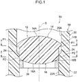
Fig. 1 is a cross-section illustrating relevant portions of a lens unit according to an exemplary embodiment, as viewed along a radial direction. -
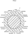
Fig. 2 is an enlarged cross-section sectioned along line 2-2 ofFig. 1 . -
Fig. 3 is an enlarged cross-section sectioned along line 3-3 ofFig. 1 . -
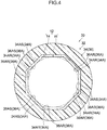
Fig. 4 is a cross-section of a lens-barrel illustrating a first modified example of a lens unit according to an exemplary embodiment. -
Fig. 5 is a cross-section corresponding toFig. 1 and illustrating a second modified example of a lens unit according to an exemplary embodiment. -
Fig. 6 is a cross-section corresponding toFig. 1 and illustrating a third modified example of a lens unit according to an exemplary embodiment. -
Fig. 7 is a cross-section corresponding toFig. 2 and illustrating a fourth modified example of a lens unit according to an exemplary embodiment. -
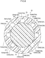
Fig. 8 is a cross-section corresponding toFig. 2 and illustrating a fifth modified example of a lens unit according to an exemplary embodiment. - A description follows regarding exemplary embodiments according to the present disclosure, with reference to the drawings. Note that in the drawings the same reference numerals are denoted to configuration elements having the same function, and explanation is omitted thereof as appropriate. Moreover, S is employed as appropriate in each of the drawings to indicate an optical axis, and a direction along the optical axis S is referred to as the optical axis direction.
- As illustrated in
Fig. 1 , alens unit 10 according to the present exemplary embodiment is configured including alens 12 made from resin or made from glass, and a lens-barrel 18 made from resin and housing thelens 12. Note that plural lenses separate from thelens 12 are also housed in the lens-barrel 18 so as to configure an optical system. Moreover, the upper side inFig. 1 is an object side, and the lower side inFig. 1 is an imaging side. - The
lens 12 is formed in a substantially circular shape when viewed from the optical axis direction, and includes a first circular shapedportion 14 and a second circular shapedportion 16 arranged in a row along the optical axis direction. As an example, thelens 12 of the present exemplary embodiment is formed with an external diameter not exceeding 15 mm. The first circular shapedportion 14 is positioned at the object side of thelens 12 and includes afirst lens section 14A including an optical surface, and a firstperipheral edge section 14B configuring a section at an outer periphery of thefirst lens section 14A. Further, The face on the object side of the first circular shapedportion 14 is curved so as to be convex on the object side. - On the other hand, The second circular shaped
portion 16 is positioned on the imaging side of thelens 12 and is integrally formed to the first circular shapedportion 14. The second circular shapedportion 16 includes asecond lens section 16A including an optical surface, and a secondperipheral edge section 16B configuring a section at an outer periphery of thesecond lens section 16A. Further, a face on the imaging side of the second circular shapedportion 16 is curved so as to be convex on the imaging side. - Here, the first circular shaped
portion 14 is formed with a larger diameter than the second circular shapedportion 16. Accordingly, the firstperipheral edge section 14B of the first circular shapedportion 14 is positioned further toward the radial direction outside than the secondperipheral edge section 16B of the second circular shapedportion 16. Further, the optical axis direction length of the first circular shapedportion 14 is shorter than the optical axis direction length of the second circular shapedportion 16. Furthermore, the firstperipheral edge section 14B of the first circular shapedportion 14 and the secondperipheral edge section 16B of the second circular shapedportion 16 respectively fit together with an inner peripheral face of the lens-barrel 18. - The lens-
barrel 18 is open at both optical axis direction ends thereof, is formed in a substantially circular cylinder shape, and is formed by resin molding. Further, a holding portion (not illustrated in the drawings) is provided at the imaging side end of the lens-barrel 18. A through hole that functions as an optical aperture is formed in this holding portion. Furthermore, a crimped portion (not illustrated in the drawings) is formed by heat crimping the object side end of the lens-barrel 18. Components of the optical system are suppressed from coming out from the lens-barrel 18 by this crimped portion. - The lens-
barrel 18 may, for example, be configured by a polyphenylene sulfide containing glass fibers and an inorganic filler. The mechanical strength is raised by making the lens-barrel 18 from a fiber reinforced plastic containing glass fibers or the like. Examples of resins that may be employed therefor include at least one type of resin selected from the group consisting of a polyamide, a polyacetal, a polycarbonate, a polyphenylene ether, a polybutylene terephthalate, a polyethylene terephthalate, a polyethylene, a syndiotactic polystyrene, a polysulfone, a polyethersulfphone, a polyphenylene sulfide, a polyarylate, a polyamide-imide, a polyetherimide, a polyetheretherketone, an acrylonitrile butadiene styrene, a polyolefin, and a modified polymer of any of these resins. The resin may also be a polymer alloy containing at least one resin selected from this group. Fibers that may be employed include glass fibers and carbon fibers, and a fiber reinforced plastic including an inorganic filler or the like may be employed. - Moreover, the above resin materials such as fiber reinforced plastic may contain glass fibers, carbon fibers, inorganic fillers, or the like as required. Making the lens-barrel from a fiber reinforced plastic containing glass fibers or the like enables a lens-barrel with a higher mechanical strength to be obtained.
- Note that the lens-
barrel 18 needs to have high light-blocking properties and light-absorbing properties. The resin employed therefor is preferably black in color, and the above resin material preferably contains a black pigment or black colorant. Configuring the lens-barrel 18 from a resin material containing a black pigment or black colorant enables the inner wall face of the lens-barrel 18 to be made black in color, thereby enabling more effective suppression of visible light from being reflected at the inner wall face of the lens-barrel 18. - The lens-
barrel 18 is configured including afirst step portion 20 and asecond step portion 22, in this sequence from the object side. Thefirst step portion 20 extends with a fixed thickness along the optical axis direction. The inner peripheral face of thefirst step portion 20 configures a first innerperipheral face 20A that the first circular shapedportion 14 fits together with. On the other hand, thesecond step portion 22 extends with a fixed thickness along the optical axis direction. The inner peripheral face of thesecond step portion 22 configures a second innerperipheral face 22A that the second circular shapedportion 16 fits together with at a position separated in the optical axis direction from the fitting section where the first circular shapedportion 14 and the first innerperipheral face 20A fit together. - A
step 24 is formed to the inner peripheral face of the lens-barrel 18 at a boundary portion between thefirst step portion 20 and thesecond step portion 22. Thestep 24 is inclined toward the radial direction inside on progression from the object side toward the imaging side. Accordingly, the first innerperipheral face 20A is positioned further to the radial direction outside than the second innerperipheral face 22A. - As illustrated in
Fig. 3 , the first innerperipheral face 20A is formed with a polygonal profile when viewed from the optical axis direction, and, as an example in the present exemplary embodiment, is formed with a substantially square shaped profile when viewed from the optical axis direction. Further, the first innerperipheral face 20A is configured including four flat faces 20AS that form each side of a square, and substantially circular arc shaped connecting portions 20AR that connect adjacent of the flat faces 20AS together. Thus, the first circular shapedportion 14 contacts each of the four flat faces 20AS, and contact portions P1 are configured at locations where the first circular shapedportion 14 and the flat faces 20AS make contact with each other. Namely, the first circular shapedportion 14 makes contact with the first innerperipheral face 20A at four locations (three or more locations) in the circumferential direction. - As illustrated in
Fig. 2 , the second innerperipheral face 22A is formed with a polygonal profile when viewed from the optical axis direction, and, as an example in the present exemplary embodiment, is formed with a substantially regular hexagonal shaped profile when viewed from the optical axis direction. Further, the second innerperipheral face 22A is configured including eight flat faces 22AS that form each side of a regular hexagon, and substantially circular arc shaped connecting portions 22AR that connect adjacent of the flat faces 22AS together. Furthermore, The second circular shapedportion 16 contacts each of the eight flat faces 22AS, and contact portions P2 are configured at locations where the second circular shapedportion 16 and the flat faces 22AS make contact with each other. Namely, the second circular shapedportion 16 makes contact with the second innerperipheral face 22A at eight locations (three or more locations) in the circumferential direction.Fig. 2 andFig. 3 are illustrated with the same orientation as each other. Thus, the four flat faces 22AS at the top, bottom, left and right inFig. 2 are formed at the same positions in the circumferential direction when viewed from the optical axis direction as the four flat faces 20AS inFig. 3 . Here, Reference to the "same positions in the circumferential direction" means that the contact portions between the circular shaped portions and the inner peripheral faces are positions aligned with each other in the circumferential direction. - As illustrated in
Fig. 1 , an optical axis direction length (fitting length) of the contact portions P1 between the first circular shapedportion 14 of thelens 12 and the first innerperipheral face 20A is shorter than an optical axis direction length of the contact portions P2 between the second circular shapedportion 16 and the second innerperipheral face 22A. - A
spacing ring 26 is disposed at the object side of thelens 12. Thespacing ring 26 is formed with a substantially ring shaped profile and fits together with the second innerperipheral face 22A of the lens-barrel 18. Further, an upper end portion of thespacing ring 26 contacts the second circular shapedportion 16 of thelens 12 at a lower face of the secondperipheral edge section 16B so as to support thelens 12 from the object side. - Explanation follows regarding the operation and effects of the present exemplary embodiment.
- In the present exemplary embodiment the first circular shaped
portion 14 of thelens 12 fits together with the first innerperipheral face 20A of the lens-barrel 18, and the second circular shapedportion 16 of thelens 12 fits together with the second innerperipheral face 22A of the lens-barrel 18. Thereby, in the present exemplary embodiment, thelens 12 makes contact with the inner peripheral face of the lens-barrel 18 at plural locations when viewed from a direction orthogonal to the optical axis direction (a radial direction of the lens-barrel 18). Thus, in the present exemplary embodiment, thelens 12 can be suppressed from tilting compared to structures in which a lens only makes contact with the inner peripheral face of the lens-barrel 18 at a single location when viewed from the radial direction of the lens-barrel 18. For example, consider a structure of a comparative example in which thelens 12 only makes contacts at the second innerperipheral face 22A. In such cases, there is a gap between the first circular shapedportion 14 of thelens 12 and the first innerperipheral face 20A of the lens-barrel 18. The object side of thelens 12 is accordingly not supported by the lens-barrel 18, and so tilting readily occurs. - Moreover, in the present exemplary embodiment, the
lens 12 is caused to contact the inner peripheral face of the lens-barrel 18 at plural locations (the first innerperipheral face 20A and the second innerperipheral face 22A), when viewed from a radial direction of the lens-barrel 18. Accordingly, in the present exemplary embodiment, there is no need to lengthen the respective fitting lengths of the first circular shapedportion 14 and the second circular shapedportion 16. Namely, in the present exemplary embodiment, thelens 12 can be suppressed from tilting even with the comparatively short contact portions P1 between the first circular shapedportion 14 and the first innerperipheral face 20A and the comparatively short contact portions P2 between the second circular shapedportion 16 and the second innerperipheral face 22A. As a result, in the present exemplary embodiment, thelens 12 can be suppressed from becoming difficult to insert into the lens-barrel 18 when assembling thelens 12 to the lens-barrel 18, enabling ease of assembly to be secured. - Further, in the present exemplary embodiment, the first circular shaped
portion 14 makes contact with the first innerperipheral face 20A at three or more locations in the circumferential direction, and the second circular shapedportion 16 fits together with the second innerperipheral face 22A at three or more locations in the circumferential direction. Accordingly, the positional precision of thelens 12 is easily secured in the present exemplary embodiment, and there is no need to lengthen the respective fitting lengths at the first circular shapedportion 14 and the second circular shapedportion 16 due to performing positioning of thelens 12 with at least one out of the first innerperipheral face 20A or the second innerperipheral face 22A. As a result, in the present exemplary embodiment, thelens 12 can be suppressed from becoming difficult to insert into the lens-barrel 18 when assembling thelens 12, enabling ease of assembly to be secured. - Moreover, in the present exemplary embodiment, the optical axis direction length of larger diameter first circular shaped
portion 14 is shorter than that of the second circular shapedportion 16. Thus, in the present exemplary embodiment, insertion of thelens 12 into the lens-barrel is easy compared to cases in which the larger diameter first circular shapedportion 14 is longer in the optical axis direction. Moreover, the fitting length at the contact portions P1 is shorter than the fitting length at the contact portions P2. Thus, in the present exemplary embodiment, by making the optical axis direction length of the contact portions P1 between the first circular shapedportion 14 and the first innerperipheral face 20A shorter in this manner, thelens 12 can be more easily inserted into the lens-barrel 18. Namely, the present exemplary embodiment enables the ease of assembly of the lens 1 2 to be raised. - Furthermore, in the present exemplary embodiment, the contact portions P2 between the second circular shaped
portion 16 and the second innerperipheral face 22A configure point contacts due to the polygonal profile of the second innerperipheral face 22A. Thus, in the present exemplary embodiment, the resistance during assembly is reduced compared to structures having face-to-face contact in which the second circular shapedportion 16 is received by a curved face, such as a structure in which the second innerperipheral face 22A is given a circular shaped profile when viewed from the optical axis direction. This enables the fitting length to be lengthened while still maintaining ease of assembly. In particular, in the present exemplary embodiment, the second innerperipheral face 22A is configured including the flat faces 22AS that form each side of a polygonal shape, and the circular arc shaped connecting portions 22AR that connect adjacent of the flat faces 22AS together. Thus, in the present exemplary embodiment, portions corresponding to the circular arc shaped connecting portions 22AR can act as escape portions for an end mill when using a cutting tool such as an end mill to cut the faces of a mold. - Furthermore, in the present exemplary embodiment, the first inner
peripheral face 20A also has a polygonal profile, similarly to the second innerperipheral face 22A. Thus, in the present exemplary embodiment, the contact portions between the first circular shapedportion 14 and the first innerperipheral face 20A also configure point contacts. This reduces the resistance during assembly compared to structures with face-to-face contact by receiving the first circular shapedportion 14 with a curved face. This enables the fitting length to be lengthened while still maintaining ease of assembly. In particular, in the present exemplary embodiment, the second innerperipheral face 22A is configured including the flat faces 20AS that form each side of a polygonal shape, and the circular arc shaped connecting portions 20AR that connect adjacent of the flat faces 20AS together. Thus in the present exemplary embodiment, portions corresponding to the circular arc shaped connecting portions 20AR can act as escape portions for an end mill when using a cutting tool such as an end mill to cut faces on a mold. - Moreover, in the present exemplary embodiment, the first inner
peripheral face 20A is positioned further to the radial direction outside than the second innerperipheral face 22A. In this manner, the present exemplary embodiment enables easier processing for the lens-barrel 18 than structures in which the first innerperipheral face 20A and the second innerperipheral face 22A are formed at the same radial direction positions to each other, namely structures in which the first innerperipheral face 20A and the second innerperipheral face 22A have the same diameter as each other. Namely, as long as the position of the first innerperipheral face 20A is further to the radial direction outside than the second innerperipheral face 22A, face cutting can be performed separately at the locations on a mold corresponding to the first innerperipheral face 20A and the locations on the mold corresponding to the second innerperipheral face 22A. - An exemplary embodiment has been described above, however, as another modified example, flat faces 34AS configuring a first inner
peripheral face 34A and flat faces 36AS configuring a second innerperipheral face 36A may be formed in the same circumferential direction positions to each other, such as in a first modified example illustrated inFig. 4 . Moreover, different profiles may be employed for the profile of the inner peripheral face of the lens-barrel, such as in a second modified example illustrated inFig. 5 , a third modified example illustrated inFig. 6 , a third modified example illustrated inFig. 7 , and a fourth modified example illustrated inFig. 8 . Note that, in the following description of the modified examples, the same reference numerals are denoted to configuration similar to that of the exemplary embodiment, and explanation thereof will be omitted as appropriate. - As illustrated in
Fig. 4 , a lens-barrel 32 configuring alens unit 30 according to the first modified example is configured including afirst step portion 34 and asecond step portion 36, in this sequence from the object side. Thefirst step portion 34 extends with a fixed thickness along the optical axis direction. The inner peripheral face of thefirst step portion 34 configures a first innerperipheral face 34A that the first circular shapedportion 14 fits together with. Thesecond step portion 36 extends with a fixed thickness along the optical axis direction. The inner peripheral face of thesecond step portion 36 configures a second innerperipheral face 36A that the second circular shapedportion 16 fits together with. Note that, for ease of explanation, thelens 12 is illustrated by dashed lines inFig. 4 , with both inner peripheral faces of the first innerperipheral face 34A and the second innerperipheral face 36A further toward the imaging side thereof (into the page in the drawing) are illustrated. - The first inner
peripheral face 34A is positioned further to the radial direction outside than the second innerperipheral face 36A. Further, the first innerperipheral face 34A and the second innerperipheral face 36A both have polygonal profiles and, in the present modified example, are formed with substantially regular octagonal profiles when viewed from the optical axis direction. More specifically, the first innerperipheral face 34A is configured including eight flat faces 34AS that form each side of a regular hexagon, and connecting portions 34AR that connect adjacent of the flat faces 34AS together. Furthermore, the first circular shapedportion 14 of thelens 12 makes contact with the first innerperipheral face 34A at eight locations (three or more locations) along the circumferential direction. - On the other hand, the second inner
peripheral face 36A is configured including eight flat faces 36AS that form each side of a regular hexagon, and connecting portions 36AR that connect adjacent of the flat faces 36AS together. Further, the second circular shapedportion 16 of thelens 12 makes contact with the second innerperipheral face 36A at eight locations (three or more locations) along the circumferential direction. Accordingly, as viewed from the optical axis direction, the flat faces 36AS of the first innerperipheral face 34A and the flat faces 36AS of the second innerperipheral face 36A are formed at the same respective positions as each other in the circumferential direction. - According to the present modified example, as viewed from the optical axis direction, the flat faces 34AS forming each side of the first inner
peripheral face 34A and the flat faces 36AS forming each side of the second innerperipheral face 36A are at the same respective positions as each other in the circumferential direction. This means that the contact portions between the first circular shapedportion 14 and the first innerperipheral face 34A are aligned in the circumferential direction with the contact portions between the second circular shapedportion 16 and the second innerperipheral face 36A. Thus in, the present modified example, the lens can be effectively suppressed from tilting. Other effects are similar to those of the exemplary embodiment above. - As illustrated in
Fig. 5 , alens unit 40 according to a second modified example is configured including alens 42 made from resin or made from glass, and a lens-barrel 48 made from resin and housing thelens 42. Further, thelens 42 is formed in a substantially circular shape when viewed from the optical axis direction, and includes a first circular shapedportion 44 and a second circular shapedportion 46 arranged in a row along the optical axis direction. The first circular shapedportion 44 is positioned at the object side of thelens 42 and includes afirst lens section 44A including an optical surface, and a firstperipheral edge section 44B configuring a section at an outer periphery of thefirst lens section 44A. A face at the object side of the first circular shapedportion 44 is curved so as to be convex on the object side. - The second circular shaped
portion 46 is positioned at the imaging side of thelens 42, and is integrally formed to the first circular shapedportion 44. The second circular shapedportion 46 includes a second lens section 46A including an optical surface and a secondperipheral edge section 46B configuring a section at the outer periphery of the second lens section 46A. The face at the imaging side of the second circular shapedportion 46 is curved so as to be convex on the imaging side. The first circular shapedportion 44 and the second circular shapedportion 46 have the same external diameters as each other. - The lens-
barrel 48 so extends with a fixed thickness along the optical axis direction, with aprotrusion portion 47 and aprotrusion portion 49 formed at two locations on the inner peripheral face of the lens-barrel 48 so as to protrude toward the inside. Theprotrusion portion 47 is positioned at the object side, and a first innerperipheral face 47A that the first circular shapedportion 44 fits together with is configured by theprotrusion portion 47. On the other hand, theprotrusion portion 49 is positioned at the object side, and a second innerperipheral face 49A that the second circular shapedportion 46 fits together with at three or more circumferential direction locations is configured by theprotrusion portion 49. Further, a fitting length of contact portions P3 between the first circular shapedportion 44 and the first innerperipheral face 47A is formed shorter than a fitting length of contact portions P4 between the second circular shapedportion 46 and the second innerperipheral face 49A. Note that, in the present modified example, the first circular shapedportion 44 and the second circular shapedportion 46 are locations defined by a relationship to the lens-barrel 48. The location on thelens 42 where contact is made with the first innerperipheral face 47A configures the first circular shapedportion 44, and the location on thelens 42 where contact is made with the second innerperipheral face 49A configures the second circular shapedportion 46. - In the present modified example, the first circular shaped
portion 44 of thelens 42 fits together with the first innerperipheral face 47A of the lens-barrel 48, and the second circular shapedportion 46 of thelens 42 fits together with the second innerperipheral face 49A of the lens-barrel 48. Accordingly, in the present modified example, thelens 42 makes contact with the inner peripheral face of the lens-barrel 48 at plural locations when viewed from a direction orthogonal to the optical axis direction (a radial direction of the lens-barrel 48). Thus, in the present modified example, thelens 42 can be suppressed from tilting in comparison to structures in which a lens only makes contact with the inner peripheral face of the lens-barrel 48 at a single location when viewed from the radial direction of the lens-barrel 48. - Further, due to the
lens 42 being fitted together with the inner peripheral face of the lens-barrel 48 at plural locations (the first innerperipheral face 47A and the second innerperipheral face 49A), when viewed from the radial direction of the lens-barrel 48, there is no need to lengthen the length along the optical axis direction of the respective contact portions of the first circular shapedportion 44 and the second circular shapedportion 46. Namely, in the present modified example, thelens 42 can be suppressed from tilting even though the contact portions P1 and the contact portions P2 are comparatively short. As a result, in the present modified example, thelens 42 can be suppressed from becoming difficult to insert when assembling thelens 42 to the lens-barrel 48, enabling ease of assembly to be secured. - Furthermore, in the present modified example, the second circular shaped
portion 46 makes contact with the second innerperipheral face 49A at three or more locations in the circumferential direction, making it easy to secure the positioning precision of thelens 42. Due to performing positioning of thelens 12 with the second innerperipheral face 49A, there is no need to lengthen the respective fitting lengths of the first circular shapedportion 44 and the first circular shapedportion 14. As a result, in the present modified example, thelens 42 can be suppressed from becoming difficult to insert into the lens-barrel 48 when assembling thelens 42 to the lens-barrel 48, enabling ease of assembly to be secured. - As illustrated in
Fig. 6 , a lens-barrel 18 configuring alens unit 50 according to a third modified example is configured including afirst step portion 52 and asecond step portion 22. Thesecond step portion 22 is configured similarly to in the exemplary embodiment, and a second circular shapedportion 16 of thelens 12 is fitted together with a second innerperipheral face 22A of thesecond step portion 22. - The inner peripheral face of the
first step portion 52 is configured by an inclined face that is inclined to the optical axis direction. More specifically, the inner peripheral face of thefirst step portion 52 is formed with a polygonal profile when viewed from the optical axis direction, and each of the inner peripheral faces configuring this polygonal profile is an inclined face inclined toward the radial direction inside on progression from the object side toward the imaging side. These inclined faces configure a first innerperipheral face 52A which the first circular shapedportion 14 of thelens 12 fits together with. The peripheral face of the firstperipheral edge section 14B of the first circular shapedportion 14 is fitted together with the first innerperipheral face 52A and inclined to correspond to the inclination of the first innerperipheral face 52A. - In the present modified example, the first inner
peripheral face 52A, which is an inclined face, guides thelens 12 when thelens 12 is being inserted from the object side into the lens-barrel 18 and fitted therein. Thus in the present modified example, positioning of thelens 12 is performed easily compared to cases in which both the first innerperipheral face 52A and the second innerperipheral face 22A are formed along the optical axis direction. - Note that although in the present modified example it is only the first inner
peripheral face 52A that is configured by an inclined face, there is no limitation thereto. For example, a configuration may be adopted in which it is only the second innerperipheral face 22A that is configured by an inclined face. In such cases, on the secondperipheral edge section 16B of the second circular shapedportion 16 that fits together with the second innerperipheral face 22A, a peripheral face thereon that fits together with the second innerperipheral face 22A is inclined to correspond to the inclination of the second innerperipheral face 22A. Moreover, a configuration may be adopted in which both the first innerperipheral face 52A and the second innerperipheral face 22A are inclined faces. - As illustrated in
Fig. 7 , a second innerperipheral face 62A of a lens-barrel 62 configuring alens unit 60 according to a fourth modified example has a polygonal profile when viewed from the optical axis direction. However, instead of each side of the polygonal profile being a flat face, the second innerperipheral face 62A is configured by eight curved faces 62AS. The respective curved faces 62AS are each curved so as to be convex on the radial direction inside, and adjacent of the curved faces 62AS are connected together by angled corners. The respective curved faces 62AS fit together with the second circular shapedportion 16 of thelens 12, and contact portions P6 are configured at locations where the curved faces 62AS and the second circular shapedportion 16 contact each other. A first inner peripheral face of the lens-barrel 62 is configured similarly to that of the exemplary embodiment above (seeFig. 3 ). - In this manner, in the present modified example, the
lens 12 can be suppressed from tilting while still securing an ease of assembly similar to that of the exemplary embodiment above, even though this is a case in which the second innerperipheral face 62A is configured by the curved faces 62AS instead of by flat faces. - Next, as illustrated in
Fig. 8 , in a fifth modified example a second innerperipheral face 72A of a lens-barrel 72 configuring alens unit 70 is configured including eight curved faces 72AS, and indentation portions 72AN connecting adjacent of the curved faces 72AS together. Further, the curved faces 72AS are respectively provided at an even spacings around the circumferential direction, are depressed toward the radial direction outside of the lens-barrel 72 and make face-to-face contact with the second circular shapedportion 16. Furthermore, the respective curved faces 72AS fit together with the second circular shapedportion 16 of thelens 12, and contact portions P7 are configured at locations (faces) where the curved faces 72AS and the second circular shapedportion 16 contact each other. - The indentation portions 72AN are formed by hollowing locations between adjacent flat faces toward the radial direction outside. Further, the first inner peripheral face of the lens-
barrel 62 is configured similarly to that of the exemplary embodiment above (seeFig. 3 ). In the present modified example, thelens 12 can be suppressed from tilting while still securing an ease of assembly similar to that of the exemplary embodiment above. Moreover, in the present modified example, due to the second circular shapedportion 16 being received by curved faces, the contact surface area with the second innerperipheral face 72A can be made larger compared to configurations in which the second circular shapedportion 16 is received at points. As a result, in the present modified example, the overall optical axis direction of thelens 12 can be suppressed from tilting. - Although the present disclosure has been described using the above exemplary embodiment and modified examples, the present disclosure is not limited to the above exemplary embodiment and modified examples, and various modifications may be made thereto in a range not departing from the spirit of the present disclosure. For example, although in the above exemplary embodiment the first inner
peripheral face 20A of the lens-barrel 18 is formed with a polygonal profile (substantially square shaped profile) when viewed from the optical axis direction, as illustrated inFig. 3 , there is no limitation thereto. The first innerperipheral face 20A may be formed with a substantially circular shaped profile when viewed from the optical axis direction. - Moreover, although in the above exemplary embodiment the second inner
peripheral face 22A of the lens-barrel 18 is formed with a substantially regular hexagonal shaped profile when viewed from the optical axis direction, as illustrated inFig. 2 , there is no limitation thereto. The second innerperipheral face 22A may have any profile that the second circular shapedportion 16 will fit together with at three or more locations in the circumferential direction. For example, the second innerperipheral face 22A may be formed with a substantially square shaped profile when viewed from the optical axis direction, to give a structure in which the second circular shapedportion 16 is fitted together therewith at four locations. - Furthermore, although in the above exemplary embodiment the first circular shaped
portion 14 and the first innerperipheral face 20A are positioned further toward the object side than the second circular shapedportion 16 and the second innerperipheral face 22A, as illustrated inFig. 1 , there is no limitation thereto. The first circular shapedportion 14 and the first innerperipheral face 20A may be disposed further toward the imaging side than the second circular shapedportion 16 and the second innerperipheral face 22A. - The entire disclosure of Japanese Patent Application No.
2016-065656 - All publications, patent applications and technical standards mentioned in the present specification are incorporated by reference in the present specification to the same extent as if each individual publication, patent application, or technical standard was specifically and individually indicated to be incorporated by reference.
Claims (12)
- A lens unit comprising:a lens including a first circular shaped portion and a second circular shaped portion arranged in a row along an optical axis direction; anda lens-barrel formed of a resin and formed in a tubular shape, the lens-barrel including:a first inner peripheral face to which the first circular shaped portion is fitted, anda second inner peripheral face to which the second circular shaped portion is fitted and is positioned separated in the optical axis direction from a fitting section where the first circular shaped portion and the first inner peripheral face are fitted, the second circular shaped portion contacts with the second inner peripheral face at three or more portions in a circumferential direction.
- The lens unit of claim 1, wherein:the second inner peripheral face is formed with a polygonal profile when viewed from the optical axis direction; andcontact portions at the second inner peripheral face that contacts with the second circular shaped portion have flat faces that forms each side of the polygonal profile.
- The lens unit of claim 2, wherein the second inner peripheral face includes curved faces formed to link adjacent of the flat faces together.
- The lens unit of claim 1, wherein a curved face is formed at a contact portion at the second inner peripheral face where contact is made with the second circular shaped portion, the curved face being depressed toward a radial direction outside of the lens-barrel when viewed from the optical axis direction and making face-to-face contact with the second circular shaped portion.
- The lens unit of any one of claim 2 to claim 4, wherein the first circular shaped portion and the first inner peripheral face contact each other at three or more portions in a circumferential direction.
- The lens unit of claim 5, wherein the first inner peripheral face has a polygonal profile when viewed from the optical axis direction.
- The lens unit of claim 6, wherein the first inner peripheral face is configured including flat faces forming each side of the polygonal profile, and circular arc shaped connection portions connecting adjacent of the flat faces together.
- The lens unit of any one of claim 1 to claim 7, wherein the first inner peripheral face is positioned further to a radial direction outside than the second inner peripheral face.
- The lens unit of claim 8, wherein a length of the first circular shaped portion in the optical axis direction is shorter than a length of the second circular shaped portion in the optical axis direction.
- The lens unit of claim 6 or claim 7, wherein:the first inner peripheral face is positioned further to a radial direction outside than the second inner peripheral face; andflat faces forming each side of the first inner peripheral face and flat faces forming each side of the second inner peripheral face are formed at the same circumferential direction positions with each other, when viewed from the optical axis direction.
- The lens unit of any one of claim 1 to claim 10, wherein:at least one of the first inner peripheral face or the second inner peripheral face includes an inclined face inclined with respect to the optical axis direction; andof the first circular shaped portion or the second circular shaped portion, a circular shaped portion that fits together with the inclined face is inclined to correspond to the inclined face.
- The lens unit of any one of claim 1 to claim 11, wherein the lens unit is a lens unit employed onboard a vehicle or employed for surveillance.
Applications Claiming Priority (2)
| Application Number | Priority Date | Filing Date | Title |
|---|---|---|---|
| JP2016065656 | 2016-03-29 | ||
| PCT/JP2017/001282 WO2017168960A1 (en) | 2016-03-29 | 2017-01-16 | Lens unit |
Publications (2)
| Publication Number | Publication Date |
|---|---|
| EP3438718A1 true EP3438718A1 (en) | 2019-02-06 |
| EP3438718A4 EP3438718A4 (en) | 2019-04-03 |
Family
ID=59964008
Family Applications (1)
| Application Number | Title | Priority Date | Filing Date |
|---|---|---|---|
| EP17773510.7A Withdrawn EP3438718A4 (en) | 2016-03-29 | 2017-01-16 | LENS UNIT |
Country Status (5)
| Country | Link |
|---|---|
| US (1) | US10901166B2 (en) |
| EP (1) | EP3438718A4 (en) |
| JP (1) | JP6936216B2 (en) |
| CN (1) | CN109073850B (en) |
| WO (1) | WO2017168960A1 (en) |
Families Citing this family (6)
| Publication number | Priority date | Publication date | Assignee | Title |
|---|---|---|---|---|
| CN112433419B (en) * | 2017-02-24 | 2022-03-25 | 大立光电股份有限公司 | Shading sheet, optical lens group, imaging lens and electronic device |
| CN111999845B (en) * | 2020-06-30 | 2022-12-20 | 瑞泰光学(常州)有限公司 | Lens module |
| JP7661724B2 (en) * | 2021-03-05 | 2025-04-15 | 株式会社Jvcケンウッド | Camera device and heating control method for camera device |
| JP7731694B2 (en) * | 2021-04-27 | 2025-09-01 | 旭化成株式会社 | Camera lens components |
| CN117784347A (en) * | 2022-09-22 | 2024-03-29 | 华为终端有限公司 | A lens, camera module and electronic device |
| CN218413080U (en) * | 2022-11-16 | 2023-01-31 | 诚瑞光学(常州)股份有限公司 | Optical-mechanical assembly |
Family Cites Families (31)
| Publication number | Priority date | Publication date | Assignee | Title |
|---|---|---|---|---|
| DE3202928A1 (en) * | 1982-01-29 | 1983-08-11 | Licinvest AG, 7002 Chur | CONTAINER FOR PHOTO PRINTS |
| JPS5941312A (en) * | 1982-08-30 | 1984-03-07 | Sanyo Chem Ind Ltd | Photosensitive composition |
| JPS5941312U (en) * | 1982-09-06 | 1984-03-16 | ミノルタ株式会社 | lens holding frame |
| JPS6286315A (en) * | 1985-10-11 | 1987-04-20 | Konishiroku Photo Ind Co Ltd | Lens structure |
| JPH06300949A (en) * | 1993-04-15 | 1994-10-28 | Asahi Optical Co Ltd | Supporting device for composite lens |
| JPH10197772A (en) * | 1997-01-09 | 1998-07-31 | Nikon Corp | Lens barrel and method of manufacturing the same |
| JP2000187142A (en) * | 1998-12-24 | 2000-07-04 | Canon Inc | Lens barrel |
| JP2001091810A (en) * | 1999-09-27 | 2001-04-06 | Fuji Photo Optical Co Ltd | Lens barrel |
| JP2002250853A (en) * | 2001-02-22 | 2002-09-06 | Ricoh Co Ltd | Lens holding device |
| JP2002350706A (en) * | 2001-05-22 | 2002-12-04 | Canon Inc | Lens barrel and photographing device |
| JP4231705B2 (en) * | 2003-01-30 | 2009-03-04 | オリンパス株式会社 | Lens frame device |
| JP2004341194A (en) * | 2003-05-15 | 2004-12-02 | Sekinosu Kk | Projection lens unit |
| JP2005202020A (en) * | 2004-01-14 | 2005-07-28 | Matsushita Electric Ind Co Ltd | Lens unit |
| JP4521210B2 (en) * | 2004-03-18 | 2010-08-11 | フジノン株式会社 | Lens barrel |
| CN100462763C (en) * | 2004-11-08 | 2009-02-18 | 松下电器产业株式会社 | Lens unit |
| JP2006154764A (en) * | 2004-11-08 | 2006-06-15 | Matsushita Electric Ind Co Ltd | Lens unit |
| JP4847020B2 (en) * | 2005-01-19 | 2011-12-28 | 日立マクセル株式会社 | Lens device |
| JP5030762B2 (en) * | 2007-12-19 | 2012-09-19 | オリンパスメディカルシステムズ株式会社 | Imaging apparatus and electronic endoscope |
| JP2009216774A (en) | 2008-03-07 | 2009-09-24 | Konica Minolta Opto Inc | Optical component and imaging unit |
| JP2011002576A (en) | 2009-06-17 | 2011-01-06 | Fujifilm Corp | Lens barrel and method for assembling the same |
| CN102116919A (en) * | 2009-12-30 | 2011-07-06 | 鸿富锦精密工业(深圳)有限公司 | Lens set and lens module using the same |
| JP5279787B2 (en) * | 2010-10-01 | 2013-09-04 | 日立マクセル株式会社 | Barrel, lens unit and assembling method of lens unit |
| JP5406165B2 (en) | 2010-10-25 | 2014-02-05 | 日立マクセル株式会社 | Lens device |
| JP5854255B2 (en) * | 2011-05-23 | 2016-02-09 | 株式会社リコー | Lens barrel, imaging device, and information device |
| JP5607845B2 (en) * | 2012-01-30 | 2014-10-15 | 富士フイルム株式会社 | Lens device |
| JP2013174670A (en) * | 2012-02-23 | 2013-09-05 | Olympus Corp | Lens unit |
| CN103513389A (en) * | 2012-06-29 | 2014-01-15 | 鸿富锦精密工业(深圳)有限公司 | Lens module |
| CN104516081A (en) * | 2013-09-30 | 2015-04-15 | 玉晶光电(厦门)有限公司 | Optical imaging lens |
| US9244245B2 (en) * | 2013-11-08 | 2016-01-26 | Institut National D'optique | Auto-centering of an optical element within a barrel |
| WO2016011544A1 (en) * | 2014-07-25 | 2016-01-28 | Institut National D'optique | Optical assemblies with tilt-controlled mounting of an optical element in a barrel |
| EP3438719A4 (en) * | 2016-03-29 | 2019-04-03 | Nanchang O-FILM Optical-Electronic Tech Co., LTD. | LENS UNIT |
-
2017
- 2017-01-16 EP EP17773510.7A patent/EP3438718A4/en not_active Withdrawn
- 2017-01-16 CN CN201780025325.7A patent/CN109073850B/en not_active Expired - Fee Related
- 2017-01-16 US US16/089,230 patent/US10901166B2/en not_active Expired - Fee Related
- 2017-01-16 WO PCT/JP2017/001282 patent/WO2017168960A1/en not_active Ceased
- 2017-01-16 JP JP2018508416A patent/JP6936216B2/en not_active Expired - Fee Related
Also Published As
| Publication number | Publication date |
|---|---|
| US20190121049A1 (en) | 2019-04-25 |
| CN109073850A (en) | 2018-12-21 |
| WO2017168960A1 (en) | 2017-10-05 |
| CN109073850B (en) | 2021-06-11 |
| US10901166B2 (en) | 2021-01-26 |
| JPWO2017168960A1 (en) | 2019-01-24 |
| JP6936216B2 (en) | 2021-09-15 |
| EP3438718A4 (en) | 2019-04-03 |
Similar Documents
| Publication | Publication Date | Title |
|---|---|---|
| US10901166B2 (en) | Lens unit | |
| US10928606B2 (en) | Lens unit | |
| US11125965B2 (en) | Lens unit | |
| US20180372983A1 (en) | Lens unit | |
| US10775582B2 (en) | Lens unit and manufacturing method of metal mold | |
| KR20160068508A (en) | Lens module | |
| JP6325377B2 (en) | Lens unit and method for manufacturing holder | |
| JP2019012111A (en) | Lens unit | |
| JP6941471B2 (en) | Lens unit | |
| US8351140B2 (en) | Lens barrel and lens module | |
| JP7129851B2 (en) | lens unit | |
| JP4498343B2 (en) | Lens unit | |
| US20110096417A1 (en) | Lens arrangement and related lens module | |
| JP6872405B2 (en) | Lens unit | |
| JP7129852B2 (en) | lens unit | |
| CN121657232A (en) | Optical lens and lens | |
| WO2018055897A1 (en) | Lens unit | |
| CN113655552A (en) | Spacer ring and lens |
Legal Events
| Date | Code | Title | Description |
|---|---|---|---|
| STAA | Information on the status of an ep patent application or granted ep patent |
Free format text: STATUS: THE INTERNATIONAL PUBLICATION HAS BEEN MADE |
|
| PUAI | Public reference made under article 153(3) epc to a published international application that has entered the european phase |
Free format text: ORIGINAL CODE: 0009012 |
|
| STAA | Information on the status of an ep patent application or granted ep patent |
Free format text: STATUS: REQUEST FOR EXAMINATION WAS MADE |
|
| 17P | Request for examination filed |
Effective date: 20181024 |
|
| AK | Designated contracting states |
Kind code of ref document: A1 Designated state(s): AL AT BE BG CH CY CZ DE DK EE ES FI FR GB GR HR HU IE IS IT LI LT LU LV MC MK MT NL NO PL PT RO RS SE SI SK SM TR |
|
| AX | Request for extension of the european patent |
Extension state: BA ME |
|
| RAP1 | Party data changed (applicant data changed or rights of an application transferred) |
Owner name: NANCHANG O-FILM OPTICAL-ELECTRONIC TECH CO., LTD. |
|
| A4 | Supplementary search report drawn up and despatched |
Effective date: 20190306 |
|
| RIC1 | Information provided on ipc code assigned before grant |
Ipc: G03B 15/00 20060101ALI20190228BHEP Ipc: G02B 7/02 20060101AFI20190228BHEP |
|
| DAV | Request for validation of the european patent (deleted) | ||
| DAX | Request for extension of the european patent (deleted) | ||
| STAA | Information on the status of an ep patent application or granted ep patent |
Free format text: STATUS: EXAMINATION IS IN PROGRESS |
|
| 17Q | First examination report despatched |
Effective date: 20200406 |
|
| RAP1 | Party data changed (applicant data changed or rights of an application transferred) |
Owner name: TIANJIN OFILM OPTO ELECTRONICS CO., LTD |
|
| GRAP | Despatch of communication of intention to grant a patent |
Free format text: ORIGINAL CODE: EPIDOSNIGR1 |
|
| STAA | Information on the status of an ep patent application or granted ep patent |
Free format text: STATUS: GRANT OF PATENT IS INTENDED |
|
| INTG | Intention to grant announced |
Effective date: 20210531 |
|
| STAA | Information on the status of an ep patent application or granted ep patent |
Free format text: STATUS: THE APPLICATION IS DEEMED TO BE WITHDRAWN |
|
| 18D | Application deemed to be withdrawn |
Effective date: 20211012 |