EP3438717A1 - Cable cabinet - Google Patents
Cable cabinet Download PDFInfo
- Publication number
- EP3438717A1 EP3438717A1 EP17306040.1A EP17306040A EP3438717A1 EP 3438717 A1 EP3438717 A1 EP 3438717A1 EP 17306040 A EP17306040 A EP 17306040A EP 3438717 A1 EP3438717 A1 EP 3438717A1
- Authority
- EP
- European Patent Office
- Prior art keywords
- cassette
- cabinet
- housing
- holding means
- connector
- Prior art date
- Legal status (The legal status is an assumption and is not a legal conclusion. Google has not performed a legal analysis and makes no representation as to the accuracy of the status listed.)
- Granted
Links
Images


Classifications
-
- G—PHYSICS
- G02—OPTICS
- G02B—OPTICAL ELEMENTS, SYSTEMS OR APPARATUS
- G02B6/00—Light guides; Structural details of arrangements comprising light guides and other optical elements, e.g. couplings
- G02B6/44—Mechanical structures for providing tensile strength and external protection for fibres, e.g. optical transmission cables
- G02B6/4439—Auxiliary devices
- G02B6/444—Systems or boxes with surplus lengths
- G02B6/4453—Cassettes
- G02B6/4455—Cassettes characterised by the way of extraction or insertion of the cassette in the distribution frame, e.g. pivoting, sliding, rotating or gliding
Definitions
- the present invention relates to a cable cabinet, such as an optical fiber cabinet, and more specifically to a cable cabinet comprising a cassette, such as an optical fiber splice cabinet comprising a cassette.
- Optical fibers are fragile due to their very small diameter, of the order of a few hundred microns, and their structure. The fibers therefore need to be handled with special precautions.
- a number of optical fibers are assembled to form a cable, which can be installed and used.
- the length of the optical fibers is limited, in the order of a few kilometers at most, and since the distance to convey the information carried by the optical fibers is generally greater than the maximum length, it is necessary to connect cables and thus the optical fibers there between.
- the fibers must be separated from the other fibers of the cable in the vicinity of that location.
- Cabinets also referred to as a splice box, splice distributor or connector cabinet, provided with one or several cassettes are therefore used to protect, splice or connect one or more fibers.
- the cassette as such usually contains at least one opening through which one or more fibers are introduced into the cassettes upon installation. The fibers are then spliced in a conventional manner inside the cassette or in other ways connected to each other.
- the cassette is mounted in a protecting cabinet that protects the fibers from external impact.
- a problem associated with prior art is that the cassettes arranged in the cabinets only have access to cable ducts arranged below the cabinet. In order to install cables or fibers from above the cabinet complex and space consuming solutions and/or additional installation work are required.
- the present invention preferably seeks to mitigate, alleviate or eliminate one or more of the above-identified deficiencies in the art and disadvantages singly or in any combination and solves at least the above mentioned problems by providing an improved connector cabinet.
- a connector cabinet for connecting cables comprising a housing, holding means and at least one connector cassette with a first side and a second side.
- the holding means is arranged to connect said at least one connector cassette to the housing of the connector cabinet, and arranged such that the cassette may be positioned such that the first or second side faces the housing of the connector cabinet.
- One single connector cabinet can thus be used for two different situations instead of having to purchase two specialized cabinets or make complex installation work. Since the cassette can be positioned in two different positions, the cassette is able to receive cables and ducts both from below and from above depending on the configuration of the cabinet. Hence, a more flexible installation process allowing easy installation independent of the arrangement of the cabinet is achieved.
- the cassette is rotatable around its central axis.
- the connector cabinet can thus be easily moved between the two different positions. This embodiment eliminates the possible requirements of having to rearrange the connector cabinet into two different parts during the change of position.
- the holding means may comprise attachment means that are adjustable so as to permit or deny the cassette to rotate around its central axis. This ensures that the connector cabinet is robust during standard use but still flexible during the installation process.
- the connector cabinet is a splice connector and the cassette is a splice cabinet.
- a method for adjusting a connector cabinet from a first position to a second position comprises the steps of providing according to the first aspect being in a first position, rotating the cassette around its central axis and rotating the connector cabinet within a housing plane so that the connector cabinet is in a second position.
- the cabinet allows for a greater degree of freedom with regard to the fibers arranged therein.
- the cabinet can be arranged such that the at least one cassette arranged therein is optimized for receiving fibers from above instead of from below.
- the cabinet thus allows for a simpler installation process and can be used both for receiving fibers from above and from below.
- FIG. 1 An embodiment of a connector cabinet 100 is shown in Fig. 1 having a housing 10.
- the connector cabinet 100 further comprises a connector cassette 20 having a first side 22a and a second side 22b, and holding means 50 arranged to connect the connector cassette 20 and the housing 10 of the connector cabinet 100.
- the housing 10 comprises a bottom side 12 arranged to be attached to a wall in or on the building to which the connector cabinet 100 is arranged.
- the bottom side 12 is thus substantially flat.
- the holding means 50 is preferably arranged at the bottom side 12 of the housing 10 which will soon be discussed more in detail.
- the housing 10 may further comprise two side walls 14a, 14b and a top wall 16.
- the housing may further comprise a bottom wall 18.
- the side walls 14a, 14b may be longitudinal walls and the top wall 16 is perpendicular to the bottom side.
- the bottom wall 18 is aligned with the bottom side.
- the housing 10 further comprises a removable top portion (not shown) that covers and protects the interior of the housing 10.
- the bottom side 12 of the housing 10 may comprise a plurality of openings or holes. These holes may be used to coil or gather optical fibers.
- the connector cabinet 100 may thus comprise means for coiling optical fibers.
- the coiling means may be holes arranged on the bottom side 12 of the housing 10 to which attachment means such as bundling straps can be arranged in order to coil and gather the optical fibers.
- the housing 10 may be constructed by metal and/or a plastic material.
- the housing 10 is constructed by a metal such as steel.
- the steel is powder coated with a galvanized sheet material.
- the material of the housing 10 shall be such that the connector cabinet 100 can be used inside and/or outside.
- the connector cabinet could for example be arranged on a wall in a building, in a cable cabinet or a ground cabinet arranged outside.
- the cabinet 100 may further comprise locking means (not shown) such as locking cylinder or the like.
- the connector cabinet 100 may comprise one or several connector cassettes 20. This allows for adaptation of the numbers of fibers that can be connected or spliced.
- the connector cabinet 100 being in the form of a splice cabinet may for example be able to splice up to 48, 96 or 192 fibers.
- the connector cabinet 100 arranged for connecting cables will be referred to as a splice cabinet 100 having a splice cassette 20 used to splice optical fibers.
- the connector cabinet could be any type of cabinet, such as for example a cabinet that connects copper wires.
- the cassette 20 has a substantially rectangular parallelepiped shape.
- the cassette 20 comprises a first side 22a, also referred to as the front side 22a, and a second side 22b, also referred to as the backside 22b (see Fig. 1d ).
- the cassette 20 further has two lateral sides 24a, 24b, a bottom end 28 and a top end 26.
- the two lateral sides 24a, 24b are arranged opposite each other and the bottom end 28 and the top end 26 are arranged opposite each other.
- the bottom end 28 of the cassette is arranged in the vicinity of the bottom wall 18 of the housing 10 and the top end 26 of the cassette is arranged in the vicinity of the top wall 16 of the housing 10.
- the backside 22b of the cassette 20 is facing the bottom side 12 of the housing 10.
- the cassette 20 may further comprise an inlet for inputting a cable of optical fibers, composed mainly of a plurality of optical fibers surrounded by a protective sheath, in the cassette 20 and an exit for outputting individual cables of optical fibers out from the cassette 20.
- the inlet and the exit are sealed against both water and air.
- the cassette 20 is provided with breakable openings used as inlets and exits. By using breakable openings, the same type of cabinets can be used for different fiber configurations. Additionally, due to the sealing the cassette 20 is subjected to as little external impact as possible from the environment, as only the necessary openings are opened. The openings could be provided at the any of the two lateral sides 24a, 24b and/or the bottom end 28 of the cassette 20.
- the splice cabinet 100 may comprise means for coiling optical fibers.
- the coiling means may be arranged in the cassette instead of the housing of the splice cabinet 100.
- the coiling means may for example be constituted by two identical drums arranged on the backside 22b of the cassette 20, where the drums are designed to accommodate optical fiber coiled in the shape of "8" around the drums.
- the holding means 50 as illustrated in Figs. 1-3 is arranged, directly or indirectly, on the bottom side 12 of the housing 10. However, in other embodiments the holding means 50 may be arranged on the top wall 16 of the housing 10 of the cabinet 100. The other end of the holding means 50 is arranged on or adjacent to the top end 26 of the cassette 20. The holding means 50 may be arranged directly to housing 10 or by a protruding portion 54 or similar arrangement that is arranged on the housing 10.
- the holding means 50 allows for movement of the cassette 20.
- the cassette 20 can thus be moved into different positions, as illustrated in Figs. 1a-d and Figs. 3a-b .
- the holding means 50 is arranged such that the cassette 20 is allowed to be positioned in two main positions, one position where the first side 22a faces the housing 10 and another position where the second side 22b faces the housing 10.
- the change of position can be achieved in several ways, for example by detaching the holding means 50 from the housing 10 and/or from the cassette 20. Additionally or alternatively, the position of the cassette 20 may be changed by rotating it around its central axis.
- the holding means 50 is detachably arranged to the cassette 20. This allows the user to easily change the cassette, add further cassettes to the cabinet 100 and/or change the position of the cassette 20. Hence, having a holding means 50 that is detectably arranged to the cassette 20 allows the cassette 20 to be moved between a first and a second position. In this embodiment, the holding means 50 may be detached in order to turn the cassette such that the first or second side faces the housing 10 and once the desired position is achieved, the holding means 50 is again attached to the cassette 20.
- the holding means 50 may be detachably arranged to the cassette 20 using attachment means such as screws and bolts. Hence in one embodiment, the user loses and withdraws the screw or bolt from the holding means 50 in order to change position of the cassette 20, and attaches and fastens the screw or bolt once the cassette is 20 in the desired position.
- the cassette 20 cannot be removed from the holding means 50 and the cassette 20 and the holding means 50 are thus fixedly arranged to each other.
- the holding means 50 is detachably arranged to the housing 10 of the cabinet 100. In this way, the position of the holding means 50 and its attached cassette 20 is movable and/or the attached cassette 20 can be changed. Hence, having a holding means that is detectably arranged to the housing allows the cassette 20 to be moved between a first and a second position. In this embodiment, the holding means 50 may be detached in order to turn the cassette such that the first or second side faces the housing 10 and once the desired position is achieved, the holding means 50 is again attached to the housing 10 of the cabinet 100.
- the holding means 50 may be detachably arranged to the housing 10 using attachment means such as screws and bolts, or by using a groove configuration.
- the groove configuration may comprise a groove and a corresponding protrusion arranged to be connected to the groove so as to arranged the holding means 50 to the housing 10.
- the holding means 50 is fixedly arranged to the housing 10 of the cabinet 100.
- the holding means 50 comprises at least two portions that are hinged together, in the embodiment shown in Fig. 1a the holding means 50 comprises two pairs of two portions that are hinged together.
- the holding means 50 may comprise a hinge, and more specifically a plate hinge. Additionally or alternatively, the holding means 50 may a ball and socket joint or any other arrangement that allows the cassette 20 to pivot and to rotate around its central axis C.
- the holding means 50 comprises attachment means 52.
- the attachment means 52 can be adjusted so as to permit or deny the cassette to rotate around its central axis C.
- the attachment means 52 is a screw fixation, and the adjustment thus comprises loosening, fastening or removing the screw.
- Figs. 1a-b the cabinet is a first cabinet position ready to be used for cables and ducts that need access to the cabinet from below.
- Figs. 3a-b the cabinet is in a second cabinet position ready to be used for cables and ducts that need access to the cabinet from above.
- Figs. 1c-d and 2 represents the steps needed in order to be able to arranged from a first cabinet position to a second cabinet position or vice versa.
- splice cabinet 100 is arranged in a first cabinet position.
- the housing 10 In a first cabinet position the housing 10 is arranged so that the top wall 16 faces upwards, i.e. away from the floor or ground arranged below the cabinet 100. In this position, the cables or ducts have access to the cassette through the bottom end 28 of the cassette 20.
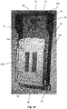
- Fig. 1a illustrates a situation where the cassette 20 is arranged in a first cassette position.
- the backside 22b of the cassette 20 is facing the bottom side 12 of the housing 10. Additionally, the cassette 20 and the housing 10 extend in basically the same direction.
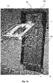
- Fig. 1b illustrates a situation where the splice cassette 20 is arranged in a second cassette position.
- the cassette 20 In the second cassette position, the cassette 20 is arranged such that an angle A1 is created between its plane and the housing plane H created by bottom side 12 of the housing 10.
- the angle A1 may vary from 1 to almost 180 degrees, and more preferably from 1 to 45 degrees.
- the holding means 50 is thus arranged to pivot the cassette around a pivot axis P.
- the pivot axis P extends in a direction parallel to the housing plane H.
- the first side, e.g. front side 22a, of the cassette 20 is at least in part facing up towards the top wall 16 and the backside 22b of the cassette is at least in part facing down towards the floor or ground.
- the cassette 20 is shown in a third cassette position.
- the holding means 50 is arranged such that the cassette 20 is able to move around its central axis C. During the movement an angle A2 is created between the central axis C of the cassette 20 and the housing plane H.
- the holding means 50 may move the cassette 20 from a position where the backside 22b, i.e. the second side, of the cassette 20 is facing upwards to a position where the front side 22a, i.e. the first side, of the cassette is facing upwards.
- Fig. 1d illustrates the cassette in a fourth position.
- the fourth cassette position is the same as the second cassette position, but where the cassette has been turned 180 degrees around its central axis.
- the first side 22a of the cassette 20 is facing the bottom side 12 of the housing 10 and/or the floor or ground on which the splice cabinet is arranged above.
- the cassette 20 is arranged such that an angle A1 is created between its plane and the bottom side 12 of the housing 10.
- the angle A1 may vary from 1 to 180 degrees, and more preferably from 1 to 45 degrees.
- the holding means 50 is configured to be able to move the cassette around its central axis as well as moving the cassette around the axis P that is parallel to the bottom side 12 of the housing 10. This has several benefits, as already have been described and will be even more apparent with reference to Figs. 2 and 3 .
- the splice cabinet 100 is rotated from a first cabinet position towards a second cabinet position.
- the cabinet 100 is rotated within the housing plane H of the housing 10, i.e. turning the direction of the top wall 16 of the housing to face up or down.
- the orientation of the splice cabinet 100 is changed so as to change the access (from below or above) to the cassette 20 in the splice cabinet 100.
- Figs. 3a-b illustrates a cabinet being in a second cabinet position.
- the housing 10 In a second cabinet position, the housing 10 is arranged so that the top wall 16 of the housing 10 faces downwards, i.e. towards the floor or ground arranged below the cabinet 100.
- the cabinet 100 In relation to the first cabinet position, the cabinet 100 has been turned 180 degrees in the housing plane H. In this position, the cables or ducts have access from above to the cassette through the bottom end 28 of the cassette 20.
- Fig. 3a illustrates a situation where the splice cassette 20 is arranged in the fifth cassette position and the cabinet is in a second cabinet position.
- the cassette 20 In the fifth cassette position, the cassette 20 is arranged such that an angle A1 is created between its plane and the housing plane H created by bottom side 12 of the housing 10.
- the angle A1 may vary from 1 to almost 180 degrees, and more preferably from 1 to 45 degrees.
- the holding means 50 is thus arranged to pivot the cassette around the pivot axis P.
- the pivot axis P extends in a direction parallel to the housing plane H.
- the fifth cassette position is thus the same as the second cassette position, with the exception that the front side 22a of the cassette 20 is at least in part facing up towards the bottom wall 18 and the backside 33b of the cassette is at least in part facing up away from the floor or ground.
- the difference between the fifth and second cassette position is that in the fifth position the cassette 20 is rotated 180 degrees around its central axis C compared to the second cassette position.
- Fig. 3b illustrates a situation where the splice cassette 20 is arranged in a sixth cassette position and the cabinet is in a second cabinet position.
- the front side 22a of the cassette 20 is facing the bottom side 12 of the housing 10.
- the backside 22b of the cassette 20 is facing the outside, or in some embodiments facing the top portion of the housing.
- the cassette 20 and the housing 10 extend in basically the same direction.
- the sixth cassette position is thus the same as the first cassette position, with the exception that the front side 22a of the cassette 20 is facing the bottom side 12 of the housing 10.
- FIG. 3a-b illustrates the cabinet 100 being ready to use for situations where it is preferred to gain access to the cassette 20 from above
- Fig. 1a-b illustrates the cabinet 100 being ready to use for situations where it is preferred to gain access to the cassette 20 from below.
- the cassette 20 has to be turned around its central axis C as described with reference to Fig. 1c .
- FIG. 4 A method for arranging a cabinet 100 from a first position to a second position is shown in Fig. 4 .
- a cabinet 100 having at least one cassette 20 as described herein is provided 200.
- the cassette 20 is pivoted 220 around a pivot axis P.
- the pivot axis P extends in a direction parallel to the housing plane H.
- the cassette is moved 230 or otherwise rotated 180 degrees around its central axis C.
- the cabinet is moved 240 or rotated 180 degrees within the housing plane H.
- attachment means 52 in the holding means 50 needs to be removed or loosened in order to be able to move or rotate the cassette around its central axis C. If this is the case, the method further comprises the optional step of adjusting 225 the holding means 50 such that it allows the cassette to rotate around its central axis C before the step 230 of moving the cassette around its axis. In one embodiment the adjustment of the holding means 50 comprises loosening the attachment means, being a screw fixation, so that the cassette is allowed to rotate.
- the holding means 50 is adjusted to fixate the cassette in its new position. This may be done directly after the step 230 of moving the cassette is done or after the step 240 where the cabinet is moved around its central axis.
- the adjustment of the holding means 50 comprises fastening the attachment means, being a screw fixation, so that the cassette is no longer allowed to rotate.
Landscapes
- Physics & Mathematics (AREA)
- General Physics & Mathematics (AREA)
- Optics & Photonics (AREA)
- Light Guides In General And Applications Therefor (AREA)
Abstract
Description
- The present invention relates to a cable cabinet, such as an optical fiber cabinet, and more specifically to a cable cabinet comprising a cassette, such as an optical fiber splice cabinet comprising a cassette.
- Optical fibers are fragile due to their very small diameter, of the order of a few hundred microns, and their structure. The fibers therefore need to be handled with special precautions. First, a number of optical fibers are assembled to form a cable, which can be installed and used. However, the length of the optical fibers is limited, in the order of a few kilometers at most, and since the distance to convey the information carried by the optical fibers is generally greater than the maximum length, it is necessary to connect cables and thus the optical fibers there between. In addition, for connecting the optical fibers to a well-defmed location (a house or apartment, for example), the fibers must be separated from the other fibers of the cable in the vicinity of that location.
- Cabinets, also referred to as a splice box, splice distributor or connector cabinet, provided with one or several cassettes are therefore used to protect, splice or connect one or more fibers. The cassette as such usually contains at least one opening through which one or more fibers are introduced into the cassettes upon installation. The fibers are then spliced in a conventional manner inside the cassette or in other ways connected to each other. The cassette is mounted in a protecting cabinet that protects the fibers from external impact.
- A problem associated with prior art is that the cassettes arranged in the cabinets only have access to cable ducts arranged below the cabinet. In order to install cables or fibers from above the cabinet complex and space consuming solutions and/or additional installation work are required.
- There is therefore a need for an improved cabinet which allows for a more flexible installation process allowing easy installation independent of the arrangement of the cabinet.
- Accordingly, the present invention preferably seeks to mitigate, alleviate or eliminate one or more of the above-identified deficiencies in the art and disadvantages singly or in any combination and solves at least the above mentioned problems by providing an improved connector cabinet.
- In a first aspect, a connector cabinet for connecting cables comprising a housing, holding means and at least one connector cassette with a first side and a second side is provided. The holding means is arranged to connect said at least one connector cassette to the housing of the connector cabinet, and arranged such that the cassette may be positioned such that the first or second side faces the housing of the connector cabinet. One single connector cabinet can thus be used for two different situations instead of having to purchase two specialized cabinets or make complex installation work. Since the cassette can be positioned in two different positions, the cassette is able to receive cables and ducts both from below and from above depending on the configuration of the cabinet. Hence, a more flexible installation process allowing easy installation independent of the arrangement of the cabinet is achieved.
- In a preferred embodiment the cassette is rotatable around its central axis. The connector cabinet can thus be easily moved between the two different positions. This embodiment eliminates the possible requirements of having to rearrange the connector cabinet into two different parts during the change of position.
- The holding means may comprise attachment means that are adjustable so as to permit or deny the cassette to rotate around its central axis. This ensures that the connector cabinet is robust during standard use but still flexible during the installation process.
- In one embodiment the connector cabinet is a splice connector and the cassette is a splice cabinet.
- In a second aspect, a method for adjusting a connector cabinet from a first position to a second position is provided. The method comprises the steps of providing according to the first aspect being in a first position, rotating the cassette around its central axis and rotating the connector cabinet within a housing plane so that the connector cabinet is in a second position.
- The cabinet allows for a greater degree of freedom with regard to the fibers arranged therein. By a simple installation step, the cabinet can be arranged such that the at least one cassette arranged therein is optimized for receiving fibers from above instead of from below. The cabinet thus allows for a simpler installation process and can be used both for receiving fibers from above and from below.
- These and other aspects, features and advantages of which the invention is capable of will be apparent and elucidated from the following description of embodiments of the present invention, reference being made to the accompanying drawings, in which
-
Fig. 1a is an isometric view of a connector cabinet being in a first cabinet position where the cassette is in a first cassette position according to an embodiment; -
Fig. 1b is an isometric view of a connector cabinet being in a first cabinet position where the cassette is in a second cassette position according to an embodiment; -
Fig. 1c is an isometric view of a connector cabinet being in a first cabinet position where the cassette is in a third cassette position according to an embodiment; -
Fig. 1d is an isometric view of a connector cabinet being in a first cabinet position where the cassette is in a fourth position according to an embodiment; -
Fig. 2 is an isometric view of a connector cabinet being moved from a first to a second cabinet position according to an embodiment; -
Fig. 3 a is an isometric view of a connector cabinet being in a second cabinet position where the cassette is in a fifth cassette position according to an embodiment; -
Fig. 3b is an isometric view of a connector cabinet being in a second cabinet position where the cassette is in a sixth cassette position according to an embodiment; and -
Fig. 4 is a block scheme of a method for arranging a connector cabinet from a first position to a second position according to an embodiment. - An embodiment of a
connector cabinet 100 is shown inFig. 1 having ahousing 10. Theconnector cabinet 100 further comprises aconnector cassette 20 having afirst side 22a and asecond side 22b, andholding means 50 arranged to connect theconnector cassette 20 and thehousing 10 of theconnector cabinet 100. Thehousing 10 comprises abottom side 12 arranged to be attached to a wall in or on the building to which theconnector cabinet 100 is arranged. Thebottom side 12 is thus substantially flat. Theholding means 50 is preferably arranged at thebottom side 12 of thehousing 10 which will soon be discussed more in detail. - The
housing 10 may further comprise twoside walls top wall 16. The housing may further comprise abottom wall 18. Theside walls top wall 16 is perpendicular to the bottom side. Thebottom wall 18 is aligned with the bottom side.. In some embodiment thehousing 10 further comprises a removable top portion (not shown) that covers and protects the interior of thehousing 10. - The
bottom side 12 of thehousing 10 may comprise a plurality of openings or holes. These holes may be used to coil or gather optical fibers. Theconnector cabinet 100 may thus comprise means for coiling optical fibers. In one embodiment the coiling means may be holes arranged on thebottom side 12 of thehousing 10 to which attachment means such as bundling straps can be arranged in order to coil and gather the optical fibers. - The
housing 10 may be constructed by metal and/or a plastic material. Preferably, thehousing 10 is constructed by a metal such as steel. In one embodiment the steel is powder coated with a galvanized sheet material. The material of thehousing 10 shall be such that theconnector cabinet 100 can be used inside and/or outside. The connector cabinet could for example be arranged on a wall in a building, in a cable cabinet or a ground cabinet arranged outside. - In some embodiments, where the
connector cabinet 100 is used in public areas, thecabinet 100 may further comprise locking means (not shown) such as locking cylinder or the like. - The
connector cabinet 100 may comprise one orseveral connector cassettes 20. This allows for adaptation of the numbers of fibers that can be connected or spliced. Theconnector cabinet 100 being in the form of a splice cabinet may for example be able to splice up to 48, 96 or 192 fibers. - In the following, the
connector cabinet 100 arranged for connecting cables will be referred to as asplice cabinet 100 having asplice cassette 20 used to splice optical fibers. However, it should be understood that the connector cabinet could be any type of cabinet, such as for example a cabinet that connects copper wires. - An embodiment of a
splice cassette 20 will now be described, but any type of cassette could be used with the inventive holding means 50. Thecassette 20 has a substantially rectangular parallelepiped shape. Thecassette 20 comprises afirst side 22a, also referred to as thefront side 22a, and asecond side 22b, also referred to as thebackside 22b (seeFig. 1d ). Thecassette 20 further has two lateral sides 24a, 24b, abottom end 28 and atop end 26. The two lateral sides 24a, 24b are arranged opposite each other and thebottom end 28 and thetop end 26 are arranged opposite each other. Thebottom end 28 of the cassette is arranged in the vicinity of thebottom wall 18 of thehousing 10 and thetop end 26 of the cassette is arranged in the vicinity of thetop wall 16 of thehousing 10. In the position of thecassette 20 shown inFig. 1a , thebackside 22b of thecassette 20 is facing thebottom side 12 of thehousing 10. - The
cassette 20 may further comprise an inlet for inputting a cable of optical fibers, composed mainly of a plurality of optical fibers surrounded by a protective sheath, in thecassette 20 and an exit for outputting individual cables of optical fibers out from thecassette 20. Preferably, the inlet and the exit are sealed against both water and air. - In some embodiments, the
cassette 20 is provided with breakable openings used as inlets and exits. By using breakable openings, the same type of cabinets can be used for different fiber configurations. Additionally, due to the sealing thecassette 20 is subjected to as little external impact as possible from the environment, as only the necessary openings are opened. The openings could be provided at the any of the two lateral sides 24a, 24b and/or thebottom end 28 of thecassette 20. - As already mentioned, the
splice cabinet 100 may comprise means for coiling optical fibers. In some embodiments, the coiling means may be arranged in the cassette instead of the housing of thesplice cabinet 100. The coiling means may for example be constituted by two identical drums arranged on thebackside 22b of thecassette 20, where the drums are designed to accommodate optical fiber coiled in the shape of "8" around the drums. - The holding means 50 as illustrated in
Figs. 1-3 is arranged, directly or indirectly, on thebottom side 12 of thehousing 10. However, in other embodiments the holding means 50 may be arranged on thetop wall 16 of thehousing 10 of thecabinet 100. The other end of the holding means 50 is arranged on or adjacent to thetop end 26 of thecassette 20. The holding means 50 may be arranged directly tohousing 10 or by a protrudingportion 54 or similar arrangement that is arranged on thehousing 10. - The holding means 50 allows for movement of the
cassette 20. Thecassette 20 can thus be moved into different positions, as illustrated inFigs. 1a-d andFigs. 3a-b . Preferably, the holding means 50 is arranged such that thecassette 20 is allowed to be positioned in two main positions, one position where thefirst side 22a faces thehousing 10 and another position where thesecond side 22b faces thehousing 10. The change of position can be achieved in several ways, for example by detaching the holding means 50 from thehousing 10 and/or from thecassette 20. Additionally or alternatively, the position of thecassette 20 may be changed by rotating it around its central axis. The different alternatives will now be described more in detail. - In some embodiments, the holding means 50 is detachably arranged to the
cassette 20. This allows the user to easily change the cassette, add further cassettes to thecabinet 100 and/or change the position of thecassette 20. Hence, having a holding means 50 that is detectably arranged to thecassette 20 allows thecassette 20 to be moved between a first and a second position. In this embodiment, the holding means 50 may be detached in order to turn the cassette such that the first or second side faces thehousing 10 and once the desired position is achieved, the holding means 50 is again attached to thecassette 20. The holding means 50 may be detachably arranged to thecassette 20 using attachment means such as screws and bolts. Hence in one embodiment, the user loses and withdraws the screw or bolt from the holding means 50 in order to change position of thecassette 20, and attaches and fastens the screw or bolt once the cassette is 20 in the desired position. - In other embodiments, the
cassette 20 cannot be removed from the holding means 50 and thecassette 20 and the holding means 50 are thus fixedly arranged to each other. - In one embodiment, the holding means 50 is detachably arranged to the
housing 10 of thecabinet 100. In this way, the position of the holding means 50 and its attachedcassette 20 is movable and/or the attachedcassette 20 can be changed. Hence, having a holding means that is detectably arranged to the housing allows thecassette 20 to be moved between a first and a second position. In this embodiment, the holding means 50 may be detached in order to turn the cassette such that the first or second side faces thehousing 10 and once the desired position is achieved, the holding means 50 is again attached to thehousing 10 of thecabinet 100. The holding means 50 may be detachably arranged to thehousing 10 using attachment means such as screws and bolts, or by using a groove configuration. The groove configuration may comprise a groove and a corresponding protrusion arranged to be connected to the groove so as to arranged the holding means 50 to thehousing 10. - In an alternative embodiment, the holding means 50 is fixedly arranged to the
housing 10 of thecabinet 100. - In one embodiment the holding means 50 comprises at least two portions that are hinged together, in the embodiment shown in
Fig. 1a the holding means 50 comprises two pairs of two portions that are hinged together. - The holding means 50 may comprise a hinge, and more specifically a plate hinge. Additionally or alternatively, the holding means 50 may a ball and socket joint or any other arrangement that allows the
cassette 20 to pivot and to rotate around its central axis C. - In some embodiments the holding means 50 comprises attachment means 52. The attachment means 52 can be adjusted so as to permit or deny the cassette to rotate around its central axis C. In one embodiment the attachment means 52 is a screw fixation, and the adjustment thus comprises loosening, fastening or removing the screw.
- In
Figs. 1a-b the cabinet is a first cabinet position ready to be used for cables and ducts that need access to the cabinet from below. InFigs. 3a-b the cabinet is in a second cabinet position ready to be used for cables and ducts that need access to the cabinet from above.Figs. 1c-d and2 represents the steps needed in order to be able to arranged from a first cabinet position to a second cabinet position or vice versa. - In
Figs. 1a-d thesplice cabinet 100 is arranged in a first cabinet position. In a first cabinet position thehousing 10 is arranged so that thetop wall 16 faces upwards, i.e. away from the floor or ground arranged below thecabinet 100. In this position, the cables or ducts have access to the cassette through thebottom end 28 of thecassette 20. -
Fig. 1a illustrates a situation where thecassette 20 is arranged in a first cassette position. In the first cassette position, thebackside 22b of thecassette 20 is facing thebottom side 12 of thehousing 10. Additionally, thecassette 20 and thehousing 10 extend in basically the same direction. -
Fig. 1b illustrates a situation where thesplice cassette 20 is arranged in a second cassette position. In the second cassette position, thecassette 20 is arranged such that an angle A1 is created between its plane and the housing plane H created bybottom side 12 of thehousing 10. In the second cassette, position the angle A1 may vary from 1 to almost 180 degrees, and more preferably from 1 to 45 degrees. The holding means 50 is thus arranged to pivot the cassette around a pivot axis P. The pivot axis P extends in a direction parallel to the housing plane H. - The first side, e.g.
front side 22a, of thecassette 20 is at least in part facing up towards thetop wall 16 and thebackside 22b of the cassette is at least in part facing down towards the floor or ground. - In
Fig. 1c , thecassette 20 is shown in a third cassette position. The holding means 50 is arranged such that thecassette 20 is able to move around its central axis C. During the movement an angle A2 is created between the central axis C of thecassette 20 and the housing plane H. The holding means 50 may move thecassette 20 from a position where thebackside 22b, i.e. the second side, of thecassette 20 is facing upwards to a position where thefront side 22a, i.e. the first side, of the cassette is facing upwards. -
Fig. 1d , illustrates the cassette in a fourth position. The fourth cassette position is the same as the second cassette position, but where the cassette has been turned 180 degrees around its central axis. Hence, thefirst side 22a of thecassette 20 is facing thebottom side 12 of thehousing 10 and/or the floor or ground on which the splice cabinet is arranged above. In the fourth cassette position, thecassette 20 is arranged such that an angle A1 is created between its plane and thebottom side 12 of thehousing 10. In the second cassette position the angle A1 may vary from 1 to 180 degrees, and more preferably from 1 to 45 degrees. - As has been illustrated in
Figs. 1a-d andFigs. 3a-b , in one embodiment the holding means 50 is configured to be able to move the cassette around its central axis as well as moving the cassette around the axis P that is parallel to thebottom side 12 of thehousing 10. This has several benefits, as already have been described and will be even more apparent with reference toFigs. 2 and3 . - In
Fig. 2 , thesplice cabinet 100 is rotated from a first cabinet position towards a second cabinet position. Thecabinet 100 is rotated within the housing plane H of thehousing 10, i.e. turning the direction of thetop wall 16 of the housing to face up or down. The orientation of thesplice cabinet 100 is changed so as to change the access (from below or above) to thecassette 20 in thesplice cabinet 100. -
Figs. 3a-b illustrates a cabinet being in a second cabinet position. In a second cabinet position, thehousing 10 is arranged so that thetop wall 16 of thehousing 10 faces downwards, i.e. towards the floor or ground arranged below thecabinet 100. In relation to the first cabinet position, thecabinet 100 has been turned 180 degrees in the housing plane H. In this position, the cables or ducts have access from above to the cassette through thebottom end 28 of thecassette 20. -
Fig. 3a illustrates a situation where thesplice cassette 20 is arranged in the fifth cassette position and the cabinet is in a second cabinet position. In the fifth cassette position, thecassette 20 is arranged such that an angle A1 is created between its plane and the housing plane H created bybottom side 12 of thehousing 10. In the second cassette position the angle A1 may vary from 1 to almost 180 degrees, and more preferably from 1 to 45 degrees. The holding means 50 is thus arranged to pivot the cassette around the pivot axis P. The pivot axis P extends in a direction parallel to the housing plane H. The fifth cassette position is thus the same as the second cassette position, with the exception that thefront side 22a of thecassette 20 is at least in part facing up towards thebottom wall 18 and the backside 33b of the cassette is at least in part facing up away from the floor or ground. Hence, the difference between the fifth and second cassette position is that in the fifth position thecassette 20 is rotated 180 degrees around its central axis C compared to the second cassette position. -
Fig. 3b illustrates a situation where thesplice cassette 20 is arranged in a sixth cassette position and the cabinet is in a second cabinet position. In a sixth cassette position, thefront side 22a of thecassette 20 is facing thebottom side 12 of thehousing 10. Hence, thebackside 22b of thecassette 20 is facing the outside, or in some embodiments facing the top portion of the housing. Additionally, thecassette 20 and thehousing 10 extend in basically the same direction. The sixth cassette position is thus the same as the first cassette position, with the exception that thefront side 22a of thecassette 20 is facing thebottom side 12 of thehousing 10. - Hence
Fig. 3a-b illustrates thecabinet 100 being ready to use for situations where it is preferred to gain access to thecassette 20 from above whereasFig. 1a-b illustrates thecabinet 100 being ready to use for situations where it is preferred to gain access to thecassette 20 from below. In order to change between the two cabinet positions thecassette 20 has to be turned around its central axis C as described with reference toFig. 1c . - A method for arranging a
cabinet 100 from a first position to a second position is shown inFig. 4 . Acabinet 100 having at least onecassette 20 as described herein is provided 200. In a next step, thecassette 20 is pivoted 220 around a pivot axis P. The pivot axis P extends in a direction parallel to the housing plane H. Further, the cassette is moved 230 or otherwise rotated 180 degrees around its central axis C. In a next step, the cabinet is moved 240 or rotated 180 degrees within the housing plane H. - In some embodiments attachment means 52 in the holding means 50 needs to be removed or loosened in order to be able to move or rotate the cassette around its central axis C. If this is the case, the method further comprises the optional step of adjusting 225 the holding means 50 such that it allows the cassette to rotate around its central axis C before the
step 230 of moving the cassette around its axis. In one embodiment the adjustment of the holding means 50 comprises loosening the attachment means, being a screw fixation, so that the cassette is allowed to rotate. - In a further step, also being optional, the holding means 50 is adjusted to fixate the cassette in its new position. This may be done directly after the
step 230 of moving the cassette is done or after thestep 240 where the cabinet is moved around its central axis. In one embodiment the adjustment of the holding means 50 comprises fastening the attachment means, being a screw fixation, so that the cassette is no longer allowed to rotate. - In the claims, the term "comprises/comprising" does not exclude the presence of other elements or steps. Additionally, although individual features may be included in different claims, these may possibly advantageously be combined, and the inclusion in different claims does not imply that a combination of features is not feasible and/or advantageous. In addition, singular references do not exclude a plurality. The terms "a", "an", "first", "second" etc do not preclude a plurality. Reference signs in the claims are provided merely as a clarifying example and shall not be construed as limiting the scope of the claims in any way.
Claims (15)
- A connector cabinet (100) for connecting cables comprising a housing (10), holding means (50) and at least one connector cassette (20) with a first side (22a) and a second side (22b), wherein said holding means (50) is arranged to connect said at least one connector cassette (20) to the housing (10) of the connector cabinet (100), and arranged such that the cassette (20) may be positioned such that the first or second side (22a, 22b) faces the housing (10).
- The cabinet (100) according to claim 1, wherein the cassette (20) is rotatable around its central axis (C).
- The cabinet (100) according to claim 1 or 2, wherein the cassette (20) is movable 180 degrees around its central axis (C).
- The cabinet (100) according to claim 1, 2 or 3, wherein the holding means (50) further is arranged such that the cassette (50) is pivotable around a pivot axis (P).
- The cabinet (100) according to claim 4, wherein said pivot axis (P) extends in a direction parallel to the plane of the connector cabinet (H).
- The cabinet (100) according to any of claims 1 to 5, wherein the holding means (50) comprises attachment means (52) that are adjustable so as to permit or deny the cassette (20) to rotate around its central axis (C).
- The cabinet (100) according to claim 6, wherein the attachment means (52) is a screw fixation.
- The cabinet (100) according to any one of the preceding claims, wherein the holding means (50) comprises at least one hinge.
- The cabinet (100) according to any one of the preceding claims, wherein the housing (10) comprises a bottom side (12) for attachment to a wall, wherein the holding means (50) is arranged at the bottom side (12) of the housing (10).
- A method for adjusting a connector cabinet (100) from a first position to a second position comprising the steps of:providing (200) a connector cabinet (100) according to any of claims 1 to 9 being in a first position;rotating (230) the cassette (20) around its central axis (C);rotating (240) the connector cabinet (100) within a housing plane (H);such that the connector cabinet (100) is in a second position.
- The method according to claim 10, wherein the method further comprises, before rotating the cassette around its central axis, the step of pivoting (220) the cassette (20) around a pivot axis (P);
- The method according to claim 9 or 10, wherein the method further comprises, before the step of rotating the cassette around its central axis, the step of (225) adjusting the holding means (50) such that it allows the cassette to rotate around its central axis (C).
- The method according to claim 12, wherein the holding means (50) comprises attachment means in the type of a screw fixation, wherein the adjusting step comprises loosening the screw fixation.
- The method according to claim 12 or 13, wherein the method further comprises, after the step of rotating the cassette around its central axis, the step of (235) adjusting the holding means (50) such that it denies the cassette to rotate around its central axis (C).
- The method according to claim 14, wherein the holding means (50) comprises attachment means in the type of a screw fixation, wherein the adjusting step comprises fastening the screw fixation.
Priority Applications (2)
| Application Number | Priority Date | Filing Date | Title |
|---|---|---|---|
| DK17306040.1T DK3438717T3 (en) | 2017-08-03 | 2017-08-03 | CABLE CABINET |
| EP17306040.1A EP3438717B1 (en) | 2017-08-03 | 2017-08-03 | Cable cabinet |
Applications Claiming Priority (1)
| Application Number | Priority Date | Filing Date | Title |
|---|---|---|---|
| EP17306040.1A EP3438717B1 (en) | 2017-08-03 | 2017-08-03 | Cable cabinet |
Publications (2)
| Publication Number | Publication Date |
|---|---|
| EP3438717A1 true EP3438717A1 (en) | 2019-02-06 |
| EP3438717B1 EP3438717B1 (en) | 2021-09-29 |
Family
ID=59592978
Family Applications (1)
| Application Number | Title | Priority Date | Filing Date |
|---|---|---|---|
| EP17306040.1A Active EP3438717B1 (en) | 2017-08-03 | 2017-08-03 | Cable cabinet |
Country Status (2)
| Country | Link |
|---|---|
| EP (1) | EP3438717B1 (en) |
| DK (1) | DK3438717T3 (en) |
Families Citing this family (1)
| Publication number | Priority date | Publication date | Assignee | Title |
|---|---|---|---|---|
| US12613391B2 (en) | 2023-05-23 | 2026-04-28 | Afl Telecommunications Llc | Bracket assembly for fiber optic closures and organizer assemblies |
Citations (4)
| Publication number | Priority date | Publication date | Assignee | Title |
|---|---|---|---|---|
| US6453107B1 (en) * | 1999-08-31 | 2002-09-17 | Lucent Technologies Inc. | Tray locking feature for a fiber enclosure |
| EP1304590A2 (en) * | 2001-10-09 | 2003-04-23 | Spirent Plc | Optical fibre splice storage enclosure |
| US20100278500A1 (en) * | 2009-04-30 | 2010-11-04 | Campos Cesar Alejandro De Los Santos | Mounting Assembly for Fiber Optic Equipment |
| KR20170043799A (en) * | 2015-10-14 | 2017-04-24 | 주식회사 장광엔지니어링 | Optical Splice Closure tray adjustable angle |
-
2017
- 2017-08-03 EP EP17306040.1A patent/EP3438717B1/en active Active
- 2017-08-03 DK DK17306040.1T patent/DK3438717T3/en active
Patent Citations (4)
| Publication number | Priority date | Publication date | Assignee | Title |
|---|---|---|---|---|
| US6453107B1 (en) * | 1999-08-31 | 2002-09-17 | Lucent Technologies Inc. | Tray locking feature for a fiber enclosure |
| EP1304590A2 (en) * | 2001-10-09 | 2003-04-23 | Spirent Plc | Optical fibre splice storage enclosure |
| US20100278500A1 (en) * | 2009-04-30 | 2010-11-04 | Campos Cesar Alejandro De Los Santos | Mounting Assembly for Fiber Optic Equipment |
| KR20170043799A (en) * | 2015-10-14 | 2017-04-24 | 주식회사 장광엔지니어링 | Optical Splice Closure tray adjustable angle |
Also Published As
| Publication number | Publication date |
|---|---|
| EP3438717B1 (en) | 2021-09-29 |
| DK3438717T3 (en) | 2021-12-20 |
Similar Documents
| Publication | Publication Date | Title |
|---|---|---|
| US8093496B2 (en) | Cable management system for moveable communication panels | |
| RU2372699C1 (en) | Cable box and organiser for communication lines and splices | |
| US11002931B2 (en) | Telecommunications tray with a cable routing path extending through a pivot hinge | |
| CN101743496B (en) | Fiber optic splice and distribution enclosure | |
| US10025055B2 (en) | Multi-positionable telecommunications tray | |
| US9291790B2 (en) | Fiber splice enclosure having removable cable port mounting plate | |
| EP3594729B1 (en) | Fiber optic cabinet and cabinet lift | |
| US20190113704A1 (en) | System and method for distributing high fiber count optical cable to network racks | |
| EP3681822B1 (en) | Reel enclosure | |
| US9983377B2 (en) | Enclosure with combined strain relief and grounding | |
| US20220365306A1 (en) | Terminal system assemblies with breakout/adapter modules | |
| RU2375731C1 (en) | Cable box splice | |
| US20170097486A1 (en) | Hardened drop terminal and clampshell | |
| US12204158B2 (en) | Telecommunications boxes with movable adapter holder | |
| US11320616B2 (en) | Utility enclosures with cable storage systems | |
| CA2657710A1 (en) | Universal fiber distribution hub | |
| EP3438717B1 (en) | Cable cabinet | |
| US20110293234A1 (en) | Internal slack storage of cable on a removable mounting surface | |
| US5270489A (en) | Utility pull box | |
| EP4080258A1 (en) | Optical terminal box for distributing optical power | |
| US10698170B2 (en) | Device for distributing trunk cable to jumper cable | |
| US8824851B2 (en) | Communications enclosure having rear mounted bracket and method of securing a cable bundle to a communications enclosure using a rear mounted bracket | |
| JP4368285B2 (en) | Optical connector rosette | |
| US8260105B2 (en) | Enclosure for housing splice trays |
Legal Events
| Date | Code | Title | Description |
|---|---|---|---|
| PUAI | Public reference made under article 153(3) epc to a published international application that has entered the european phase |
Free format text: ORIGINAL CODE: 0009012 |
|
| STAA | Information on the status of an ep patent application or granted ep patent |
Free format text: STATUS: REQUEST FOR EXAMINATION WAS MADE |
|
| 17P | Request for examination filed |
Effective date: 20180614 |
|
| AK | Designated contracting states |
Kind code of ref document: A1 Designated state(s): AL AT BE BG CH CY CZ DE DK EE ES FI FR GB GR HR HU IE IS IT LI LT LU LV MC MK MT NL NO PL PT RO RS SE SI SK SM TR |
|
| AX | Request for extension of the european patent |
Extension state: BA ME |
|
| GRAP | Despatch of communication of intention to grant a patent |
Free format text: ORIGINAL CODE: EPIDOSNIGR1 |
|
| STAA | Information on the status of an ep patent application or granted ep patent |
Free format text: STATUS: GRANT OF PATENT IS INTENDED |
|
| GRAJ | Information related to disapproval of communication of intention to grant by the applicant or resumption of examination proceedings by the epo deleted |
Free format text: ORIGINAL CODE: EPIDOSDIGR1 |
|
| STAA | Information on the status of an ep patent application or granted ep patent |
Free format text: STATUS: REQUEST FOR EXAMINATION WAS MADE |
|
| INTG | Intention to grant announced |
Effective date: 20201110 |
|
| INTC | Intention to grant announced (deleted) | ||
| GRAP | Despatch of communication of intention to grant a patent |
Free format text: ORIGINAL CODE: EPIDOSNIGR1 |
|
| STAA | Information on the status of an ep patent application or granted ep patent |
Free format text: STATUS: GRANT OF PATENT IS INTENDED |
|
| INTG | Intention to grant announced |
Effective date: 20210329 |
|
| GRAS | Grant fee paid |
Free format text: ORIGINAL CODE: EPIDOSNIGR3 |
|
| GRAA | (expected) grant |
Free format text: ORIGINAL CODE: 0009210 |
|
| STAA | Information on the status of an ep patent application or granted ep patent |
Free format text: STATUS: THE PATENT HAS BEEN GRANTED |
|
| AK | Designated contracting states |
Kind code of ref document: B1 Designated state(s): AL AT BE BG CH CY CZ DE DK EE ES FI FR GB GR HR HU IE IS IT LI LT LU LV MC MK MT NL NO PL PT RO RS SE SI SK SM TR |
|
| REG | Reference to a national code |
Ref country code: GB Ref legal event code: FG4D |
|
| REG | Reference to a national code |
Ref country code: CH Ref legal event code: EP Ref country code: AT Ref legal event code: REF Ref document number: 1434699 Country of ref document: AT Kind code of ref document: T Effective date: 20211015 |
|
| REG | Reference to a national code |
Ref country code: DE Ref legal event code: R096 Ref document number: 602017046694 Country of ref document: DE |
|
| REG | Reference to a national code |
Ref country code: IE Ref legal event code: FG4D |
|
| REG | Reference to a national code |
Ref country code: DK Ref legal event code: T3 Effective date: 20211216 |
|
| REG | Reference to a national code |
Ref country code: SE Ref legal event code: TRGR |
|
| REG | Reference to a national code |
Ref country code: LT Ref legal event code: MG9D |
|
| PG25 | Lapsed in a contracting state [announced via postgrant information from national office to epo] |
Ref country code: HR Free format text: LAPSE BECAUSE OF FAILURE TO SUBMIT A TRANSLATION OF THE DESCRIPTION OR TO PAY THE FEE WITHIN THE PRESCRIBED TIME-LIMIT Effective date: 20210929 Ref country code: RS Free format text: LAPSE BECAUSE OF FAILURE TO SUBMIT A TRANSLATION OF THE DESCRIPTION OR TO PAY THE FEE WITHIN THE PRESCRIBED TIME-LIMIT Effective date: 20210929 Ref country code: LT Free format text: LAPSE BECAUSE OF FAILURE TO SUBMIT A TRANSLATION OF THE DESCRIPTION OR TO PAY THE FEE WITHIN THE PRESCRIBED TIME-LIMIT Effective date: 20210929 Ref country code: BG Free format text: LAPSE BECAUSE OF FAILURE TO SUBMIT A TRANSLATION OF THE DESCRIPTION OR TO PAY THE FEE WITHIN THE PRESCRIBED TIME-LIMIT Effective date: 20211229 Ref country code: FI Free format text: LAPSE BECAUSE OF FAILURE TO SUBMIT A TRANSLATION OF THE DESCRIPTION OR TO PAY THE FEE WITHIN THE PRESCRIBED TIME-LIMIT Effective date: 20210929 Ref country code: NO Free format text: LAPSE BECAUSE OF FAILURE TO SUBMIT A TRANSLATION OF THE DESCRIPTION OR TO PAY THE FEE WITHIN THE PRESCRIBED TIME-LIMIT Effective date: 20211229 |
|
| REG | Reference to a national code |
Ref country code: NL Ref legal event code: MP Effective date: 20210929 |
|
| REG | Reference to a national code |
Ref country code: AT Ref legal event code: MK05 Ref document number: 1434699 Country of ref document: AT Kind code of ref document: T Effective date: 20210929 |
|
| PG25 | Lapsed in a contracting state [announced via postgrant information from national office to epo] |
Ref country code: LV Free format text: LAPSE BECAUSE OF FAILURE TO SUBMIT A TRANSLATION OF THE DESCRIPTION OR TO PAY THE FEE WITHIN THE PRESCRIBED TIME-LIMIT Effective date: 20210929 Ref country code: GR Free format text: LAPSE BECAUSE OF FAILURE TO SUBMIT A TRANSLATION OF THE DESCRIPTION OR TO PAY THE FEE WITHIN THE PRESCRIBED TIME-LIMIT Effective date: 20211230 |
|
| PG25 | Lapsed in a contracting state [announced via postgrant information from national office to epo] |
Ref country code: AT Free format text: LAPSE BECAUSE OF FAILURE TO SUBMIT A TRANSLATION OF THE DESCRIPTION OR TO PAY THE FEE WITHIN THE PRESCRIBED TIME-LIMIT Effective date: 20210929 |
|
| PG25 | Lapsed in a contracting state [announced via postgrant information from national office to epo] |
Ref country code: IS Free format text: LAPSE BECAUSE OF FAILURE TO SUBMIT A TRANSLATION OF THE DESCRIPTION OR TO PAY THE FEE WITHIN THE PRESCRIBED TIME-LIMIT Effective date: 20220129 Ref country code: SK Free format text: LAPSE BECAUSE OF FAILURE TO SUBMIT A TRANSLATION OF THE DESCRIPTION OR TO PAY THE FEE WITHIN THE PRESCRIBED TIME-LIMIT Effective date: 20210929 Ref country code: RO Free format text: LAPSE BECAUSE OF FAILURE TO SUBMIT A TRANSLATION OF THE DESCRIPTION OR TO PAY THE FEE WITHIN THE PRESCRIBED TIME-LIMIT Effective date: 20210929 Ref country code: PT Free format text: LAPSE BECAUSE OF FAILURE TO SUBMIT A TRANSLATION OF THE DESCRIPTION OR TO PAY THE FEE WITHIN THE PRESCRIBED TIME-LIMIT Effective date: 20220131 Ref country code: PL Free format text: LAPSE BECAUSE OF FAILURE TO SUBMIT A TRANSLATION OF THE DESCRIPTION OR TO PAY THE FEE WITHIN THE PRESCRIBED TIME-LIMIT Effective date: 20210929 Ref country code: NL Free format text: LAPSE BECAUSE OF FAILURE TO SUBMIT A TRANSLATION OF THE DESCRIPTION OR TO PAY THE FEE WITHIN THE PRESCRIBED TIME-LIMIT Effective date: 20210929 Ref country code: ES Free format text: LAPSE BECAUSE OF FAILURE TO SUBMIT A TRANSLATION OF THE DESCRIPTION OR TO PAY THE FEE WITHIN THE PRESCRIBED TIME-LIMIT Effective date: 20210929 Ref country code: EE Free format text: LAPSE BECAUSE OF FAILURE TO SUBMIT A TRANSLATION OF THE DESCRIPTION OR TO PAY THE FEE WITHIN THE PRESCRIBED TIME-LIMIT Effective date: 20210929 Ref country code: CZ Free format text: LAPSE BECAUSE OF FAILURE TO SUBMIT A TRANSLATION OF THE DESCRIPTION OR TO PAY THE FEE WITHIN THE PRESCRIBED TIME-LIMIT Effective date: 20210929 Ref country code: AL Free format text: LAPSE BECAUSE OF FAILURE TO SUBMIT A TRANSLATION OF THE DESCRIPTION OR TO PAY THE FEE WITHIN THE PRESCRIBED TIME-LIMIT Effective date: 20210929 |
|
| REG | Reference to a national code |
Ref country code: DE Ref legal event code: R097 Ref document number: 602017046694 Country of ref document: DE |
|
| PLBE | No opposition filed within time limit |
Free format text: ORIGINAL CODE: 0009261 |
|
| STAA | Information on the status of an ep patent application or granted ep patent |
Free format text: STATUS: NO OPPOSITION FILED WITHIN TIME LIMIT |
|
| 26N | No opposition filed |
Effective date: 20220630 |
|
| PG25 | Lapsed in a contracting state [announced via postgrant information from national office to epo] |
Ref country code: SI Free format text: LAPSE BECAUSE OF FAILURE TO SUBMIT A TRANSLATION OF THE DESCRIPTION OR TO PAY THE FEE WITHIN THE PRESCRIBED TIME-LIMIT Effective date: 20210929 |
|
| PG25 | Lapsed in a contracting state [announced via postgrant information from national office to epo] |
Ref country code: MC Free format text: LAPSE BECAUSE OF FAILURE TO SUBMIT A TRANSLATION OF THE DESCRIPTION OR TO PAY THE FEE WITHIN THE PRESCRIBED TIME-LIMIT Effective date: 20210929 |
|
| REG | Reference to a national code |
Ref country code: CH Ref legal event code: PL |
|
| GBPC | Gb: european patent ceased through non-payment of renewal fee |
Effective date: 20220803 |
|
| PG25 | Lapsed in a contracting state [announced via postgrant information from national office to epo] |
Ref country code: LU Free format text: LAPSE BECAUSE OF NON-PAYMENT OF DUE FEES Effective date: 20220803 Ref country code: LI Free format text: LAPSE BECAUSE OF NON-PAYMENT OF DUE FEES Effective date: 20220831 Ref country code: CH Free format text: LAPSE BECAUSE OF NON-PAYMENT OF DUE FEES Effective date: 20220831 |
|
| REG | Reference to a national code |
Ref country code: BE Ref legal event code: MM Effective date: 20220831 |
|
| PG25 | Lapsed in a contracting state [announced via postgrant information from national office to epo] |
Ref country code: IE Free format text: LAPSE BECAUSE OF NON-PAYMENT OF DUE FEES Effective date: 20220803 |
|
| PG25 | Lapsed in a contracting state [announced via postgrant information from national office to epo] |
Ref country code: BE Free format text: LAPSE BECAUSE OF NON-PAYMENT OF DUE FEES Effective date: 20220831 |
|
| PG25 | Lapsed in a contracting state [announced via postgrant information from national office to epo] |
Ref country code: GB Free format text: LAPSE BECAUSE OF NON-PAYMENT OF DUE FEES Effective date: 20220803 |
|
| PG25 | Lapsed in a contracting state [announced via postgrant information from national office to epo] |
Ref country code: HU Free format text: LAPSE BECAUSE OF FAILURE TO SUBMIT A TRANSLATION OF THE DESCRIPTION OR TO PAY THE FEE WITHIN THE PRESCRIBED TIME-LIMIT; INVALID AB INITIO Effective date: 20170803 |
|
| PG25 | Lapsed in a contracting state [announced via postgrant information from national office to epo] |
Ref country code: SM Free format text: LAPSE BECAUSE OF FAILURE TO SUBMIT A TRANSLATION OF THE DESCRIPTION OR TO PAY THE FEE WITHIN THE PRESCRIBED TIME-LIMIT Effective date: 20210929 Ref country code: MK Free format text: LAPSE BECAUSE OF FAILURE TO SUBMIT A TRANSLATION OF THE DESCRIPTION OR TO PAY THE FEE WITHIN THE PRESCRIBED TIME-LIMIT Effective date: 20210929 Ref country code: CY Free format text: LAPSE BECAUSE OF FAILURE TO SUBMIT A TRANSLATION OF THE DESCRIPTION OR TO PAY THE FEE WITHIN THE PRESCRIBED TIME-LIMIT Effective date: 20210929 |
|
| PG25 | Lapsed in a contracting state [announced via postgrant information from national office to epo] |
Ref country code: MT Free format text: LAPSE BECAUSE OF FAILURE TO SUBMIT A TRANSLATION OF THE DESCRIPTION OR TO PAY THE FEE WITHIN THE PRESCRIBED TIME-LIMIT Effective date: 20210929 |
|
| PGFP | Annual fee paid to national office [announced via postgrant information from national office to epo] |
Ref country code: DK Payment date: 20250707 Year of fee payment: 9 Ref country code: DE Payment date: 20250708 Year of fee payment: 9 |
|
| PGFP | Annual fee paid to national office [announced via postgrant information from national office to epo] |
Ref country code: IT Payment date: 20250617 Year of fee payment: 9 |
|
| PGFP | Annual fee paid to national office [announced via postgrant information from national office to epo] |
Ref country code: FR Payment date: 20250707 Year of fee payment: 9 |
|
| PGFP | Annual fee paid to national office [announced via postgrant information from national office to epo] |
Ref country code: SE Payment date: 20250707 Year of fee payment: 9 |
|
| PG25 | Lapsed in a contracting state [announced via postgrant information from national office to epo] |
Ref country code: TR Free format text: LAPSE BECAUSE OF FAILURE TO SUBMIT A TRANSLATION OF THE DESCRIPTION OR TO PAY THE FEE WITHIN THE PRESCRIBED TIME-LIMIT Effective date: 20210929 |