EP3438700B1 - Method for operating a gnss receiver, with gnss signal deselection - Google Patents
Method for operating a gnss receiver, with gnss signal deselection Download PDFInfo
- Publication number
- EP3438700B1 EP3438700B1 EP17184536.5A EP17184536A EP3438700B1 EP 3438700 B1 EP3438700 B1 EP 3438700B1 EP 17184536 A EP17184536 A EP 17184536A EP 3438700 B1 EP3438700 B1 EP 3438700B1
- Authority
- EP
- European Patent Office
- Prior art keywords
- gnss
- position determination
- received
- satellite
- receiver
- Prior art date
- Legal status (The legal status is an assumption and is not a legal conclusion. Google has not performed a legal analysis and makes no representation as to the accuracy of the status listed.)
- Active
Links
Images









Classifications
-
- G—PHYSICS
- G01—MEASURING; TESTING
- G01S—RADIO DIRECTION-FINDING; RADIO NAVIGATION; DETERMINING DISTANCE OR VELOCITY BY USE OF RADIO WAVES; LOCATING OR PRESENCE-DETECTING BY USE OF THE REFLECTION OR RERADIATION OF RADIO WAVES; ANALOGOUS ARRANGEMENTS USING OTHER WAVES
- G01S19/00—Satellite radio beacon positioning systems; Determining position, velocity or attitude using signals transmitted by such systems
- G01S19/01—Satellite radio beacon positioning systems transmitting time-stamped messages, e.g. GPS [Global Positioning System], GLONASS [Global Orbiting Navigation Satellite System] or GALILEO
- G01S19/13—Receivers
- G01S19/23—Testing, monitoring, correcting or calibrating of receiver elements
- G01S19/235—Calibration of receiver components
-
- G—PHYSICS
- G01—MEASURING; TESTING
- G01S—RADIO DIRECTION-FINDING; RADIO NAVIGATION; DETERMINING DISTANCE OR VELOCITY BY USE OF RADIO WAVES; LOCATING OR PRESENCE-DETECTING BY USE OF THE REFLECTION OR RERADIATION OF RADIO WAVES; ANALOGOUS ARRANGEMENTS USING OTHER WAVES
- G01S19/00—Satellite radio beacon positioning systems; Determining position, velocity or attitude using signals transmitted by such systems
- G01S19/01—Satellite radio beacon positioning systems transmitting time-stamped messages, e.g. GPS [Global Positioning System], GLONASS [Global Orbiting Navigation Satellite System] or GALILEO
- G01S19/13—Receivers
- G01S19/22—Multipath-related issues
-
- G—PHYSICS
- G06—COMPUTING OR CALCULATING; COUNTING
- G06F—ELECTRIC DIGITAL DATA PROCESSING
- G06F17/00—Digital computing or data processing equipment or methods, specially adapted for specific functions
- G06F17/10—Complex mathematical operations
- G06F17/18—Complex mathematical operations for evaluating statistical data, e.g. average values, frequency distributions, probability functions, regression analysis
-
- H—ELECTRICITY
- H04—ELECTRIC COMMUNICATION TECHNIQUE
- H04L—TRANSMISSION OF DIGITAL INFORMATION, e.g. TELEGRAPHIC COMMUNICATION
- H04L27/00—Modulated-carrier systems
- H04L27/18—Phase-modulated carrier systems, i.e. using phase-shift keying
- H04L27/22—Demodulator circuits; Receiver circuits
- H04L27/227—Demodulator circuits; Receiver circuits using coherent demodulation
- H04L27/2275—Demodulator circuits; Receiver circuits using coherent demodulation wherein the carrier recovery circuit uses the received modulated signals
- H04L27/2278—Demodulator circuits; Receiver circuits using coherent demodulation wherein the carrier recovery circuit uses the received modulated signals using correlation techniques, e.g. for spread spectrum signals
Definitions
- GNSS Global navigation satellite system
- GNSS Global navigation satellite system
- receivers are used to determine the position of, for example, moving vehicles such as a plane or a ship.
- a number of satellites orbiting in space regularly send out GNSS code signals, which are correlated with reference signals (also called replica signals) in order to determine a time delay between the transmission and the arrival at the GNSS receiver.
- reference signals also called replica signals
- time delays may be used to determine distances to the respective satellites, which move on known trajectories, so position information (such as geographical longitude, latitude and height) can be calculated.
- the only signal path of GNSS code signals is directly from the satellite to the GNSS receiver.
- the same GNSS signal from a satellite may arrive multiple times at the GNSS receiver, since signal reflections may occur, for example, at buildings or on the ground.
- Indirect signal paths are longer than the direct signal path.
- a superposition of the direct signal and indirect signals is obtained, what makes determination of the time delay of the direct signal more difficult.
- an autocorrelation function is calculated for different chip spacings (time shifts). If the direct signal is by far the strongest signal, then the chip spacing of the maximum of the autocorrelation function may be taken as the prompt (undelayed) chip spacing. However, multipath signal components (from indirect signals) may shift the maximum of the autocorrelation function with respect to the "true" prompt chip spacing, which can result in errors in position determination.
- EP 2 793 050 B1 proposes in a GNSS signal processing method to obtain autocorrelation values for a first and a second early replica signal, and a first and second late replica signal, and to calculate an early late differential value ⁇ CV EL from a first late correlation value CV L and a first early correlation value CV E . Further, an early differential signal ⁇ CV E and a late differential signal ⁇ CV L are calculated. Then an error detection value is calculated using ⁇ CV EL and either ⁇ CV L and ⁇ CV E . Depending on the comparison of ⁇ CV EL , ⁇ CV L and ⁇ CV E with some thresholds, different methods for calculating the error detection value are applied. The error detection value is used for controlling a code phase of the prompt replica signal.
- EP 2 793 050 B1 intends to increase the reliability of determining the "true" prompt replica signal when considerable multipath signal components are present in a received GNSS code signal.
- This object is achieved, in accordance with the invention and claim 1, by a method known from the prior art and further characterized in that during analysis of the multitude of function values of the autocorrelation function, a bias removal is performed, subtracting corresponding function values of an autocorrelation function that would result from a received GNSS code signal of the satellite unaffected by multipath signal components, and that the multitude of function values contribute to the test metric in an order higher than first order.
- GNSS code signals which are affected by too much multipath signal components are excluded from positon determination.
- errors in position determination are significantly reduced.
- a GNSS receiver has contact to more satellites than necessary for position determination.
- four satellites are necessary for position determination (three for three space coordinates, and one for clock synchronization), but typically six or more, and often eight or more satellites have contact to the receiver. Therefore, exclusion of a few GNSS code signals from the available satellites will, most often, not hinder the position determination.
- including a GNSS code signal with significant multipath signal components may severely distort the position determination.
- a test metric (or "monitor") is obtained (or calculated), which is based on function values of the autocorrelation function.
- the test metric basically measures deviations of the autocorrelation function by means of the function values at the chosen ship spacings as compared to an autocorrelation function free from multipath errors.
- the invention applies the following: The function values are chosen asymmetrically with respect to the prompt chip spacing. The inventors found that this leads to a more reliable multipath signal component detection. Typically, the chosen asymmetry applies both to the number of functional values on both sides of the prompt chip spacing, and the chip spacing intervals covered on both sides of the prompt chip spacing.
- the prompt chip spacing can be assumed to be at the maximum of the autocorrelation function for this purpose; its location is typically determined with an early minus late discriminator whose S-curve zero-crossing may be used for determining the prompt chip spacing.
- multipath signal components lead to asymmetric distortions of the autocorrelation function; this behavior can be best captured and investigated with asymmetrically chosen functional values.
- the autocorrelation function is typically obtained (calculated) only for a limited number of discrete chip spacings (chip positions).
- a bias removal is performed on the function values, subtracting corresponding values of an autocorrelation function that would result from an undistorted ("direct only") GNSS code signal. This reduces or avoids contributions to the test metric resulting from the asymmetric choice of functional values as such, and may reduce noise in the test metric significantly.
- a removal of a "nominal bias" is done.
- the nominal bias corresponds to a deviation of a real autocorrelation function for a received GNSS signal unaffected by multipath signal components, as compared to an ideal (triangular) autocorrelation function.
- the nominal bias is typically composed of receiver inherent correlator properties and hardware delays, as well as a satellite specific component.
- the nominal bias may disguise (i.e. impede detection of) the multipath signal components, and taking it into account (in particular by subtracting it) in turn facilitates detection of multipath signal components accordingly.
- a real autocorrelation function for a received GNSS signal unaffected by multipath signal components directly as a bias to be subtracted from the autocorrelation function obtained with the received GNSS code signal (possibly) containing multipath signal components.
- a normalization is done in this step, too.
- the autocorrelation function that would result from a received GNSS code signal of the satellite unaffected by multipath signal components is experimentally recorded or simulated in advance.
- test metric (or monitor) as a function of the amount of "error" contained becomes much steeper as compared to a linear metric. This makes multipath signal components much easier to detect and to quantify, and wrong detection of multipath signal components much less likely.
- the GNSS code signal is typically a diffusion code (which is individually set for each satellite) and code modulated onto a carrier wave having a predetermined frequency.
- the position determination in accordance with the invention may comprise the determination of space coordinates, in particular three space coordinates (such as geographical longitude, geographical latitude and height above a reference ellipsoid) of the GNSS receiver from the suitable GNSS code signals, or may comprise the determination of correction data (such as clock error or differential range errors), which contains a position information about the GNSS receiver obtained from the suitable GNSS code signals, and which is provided to other GNSS receivers.
- space coordinates in particular three space coordinates (such as geographical longitude, geographical latitude and height above a reference ellipsoid) of the GNSS receiver from the suitable GNSS code signals
- correction data such as clock error or differential range errors
- the position determination is "instantaneous", and typically repeated consecutively, so a position information can be updated quasi-continuously.
- the position information as such may be derived from the propagation time of the received GNSS code signals (i.e. the shifts of the received GNSS code signals with respect to the corresponding reference signals, which indicate a distance of the GNSS receiver to the respective satellite each).
- a GNSS code signal can be considered suitable for position determination if it is sufficiently free from errors (corruption) due to multipath signal components, in particular such that the propagation time can be determined with good accuracy resp. reliability.
- the GNSS receiver comprises an antenna and a sensor.
- the GNSS receiver is typically installed on a vehicle (such as a train or an aircraft), but may also be stationary, or may be carried by a person.
- the prompt chip spacing is chosen at the maximum of the autocorrelation function. This is particularly simple. Position determination errors due to wrong prompt chip spacing are unlikely since GNSS code signals strongly affected by multipath signal components (which could shift the prompt chip spacing with respect to the maximum) have been excluded.
- the chip spacings of the multitude of function values of the autocorrelation function are chosen predominantly, preferably completely, on the late side with respect to the prompt chip spacing. This has shown particularly reliable detection of multipath signal components. Signal paths including a reflection are longer than the direct signal path, and therefore will appear on the late side. With this variant, this asymmetry in the autocorrelation function will be better covered.
- pairwise differences of functional values with successive chip spacings are calculated, and these differences are used to calculate the test metric. This has been found to reduce signal noise in the test metric in many situations. Bias removal may be done on the functional values before calculating the difference, or may be done on the differences. Alternatively, the functional values themselves (after bias removal) may be directly used to calculate the test metric.
- bias removal encompasses a normalization and/or variance scaling. This may reduce noise and makes the contribution of the various function values comparable.
- the functional values contribute to the test metric in second or higher order, in particular wherein the functional values contribute to the test metric exponentially. This makes multipath signal components even easier to detect. It is also possible that the functional values contribute in third order (cubic), or fourth order, or even higher.
- the test metric may be calculated as a root mean square value. Preferred are even orders. In general, and in particular in case of odd orders, absolute values of contributions to the test metric should be calculated.
- a particularly advantageous variant provides that in said decision the test metric is used such that in case the test metric is larger than a critical value, the received GNSS code signal is considered unsuitable for position determination. This is a particularly simple procedure. If necessary, an absolute value may be generated before doing the comparison with the critical value. Alternatively, a range or ranges of values may be defined for the test metric, and a received GNSS code signal is considered unsuitable for position determination if its test metric is outside said ("allowed") range or ranges.
- a variant which is characterized in that position determinations are done repeatedly, that carrier waves carrying the GNSS code signals undergo a low pass filtering, and that in case a received GNSS code signal of a satellite has been found unsuitable for position determination using the test metric, a number of subsequent received GNSS code signals of the same satellite will be considered as unsuitable for position determination, too, regardless of obtained test metrics for these subsequent GNSS code signals.
- the low pass filtering of the carrier wave reduces noise.
- the test metric is not low pass filtered or low pass filtered with a time constant shorter than the time constant of the low pass filtering of the carrier wave, resulting in a "non-coherent" test metric.
- the detected multipath corruption affects the position determination with delay, and the blocking of the number of subsequent GNSS code signals avoids entry of the multipath corruption into the position determination.
- the number of subsequent received GNSS code signals depends on the time constant of the low pass filtering (or smoothing) of the carrier wave (or on the difference of time constants, in case the test metric is also low pass filtered). Note that in each repetition of position determination, newly received GNSS code signals are used.
- Another variant is characterized in that position determinations are done repeatedly, that carrier waves carrying the GNSS code signals undergo a low pass filtering, and that said low pass filtering is reproduced in the test metric.
- the low pass filtering of the carrier wave reduces noise.
- the low pass filtering of the carrier wave and the reproduced low pass filtering of the test metric have basically the same signal properties in terms of spectral density and timely behavior.
- the low pass filter applied to the test metric will in many cases not be identical to the low pass filter used in the processing of the GNSS code signal in the receiver processing for position determination. In this situation, the low pass filter applied to the test metric models the relevant signal characteristics of the filter applied to the GNSS code signal processing.
- a "coherent" test metric can be obtained, despite of the delayed arrival of the multipath corruption at position determination.
- a highly preferred variant provides that a number N of GNSS receivers are operated simultaneously, with N ⁇ 2, wherein the different GNSS receivers receive GNSS code signals from a number J of satellites, with J ⁇ 2, and that the decision whether a particular GNSS code signal from a particular satellite received at a particular GNSS receiver is suitable for a position determination or unsuitable for a position determination due to multipath signal components is not only depending on the test metric of this particular GNSS code signal, but also depending on the test metrics of GNSS code signals received by the other GNSS receivers and/or from the other satellites.
- the position determination may be further improved in accuracy.
- Non-common errors at different GNSS receivers may be reduced, for example by averaging obtained signal information.
- At least some of the GNSS code signals received at the N different GNSS receivers originate from the same J satellites.
- defects at receivers or satellites may be found which corrupt position determination.
- at least one additional discriminator is applied in order to find out whether the particular GNSS code signal may be corrupted (due to multipath signal components or other causes). This increases accuracy and reliability of the position determination.
- the additional discriminator is applied to all received GNSS code signals.
- the test metrics of GNSS code signals received by the other GNSS receivers and/or from the other satellites which exceed a threshold, indicating a multipath error; these are preferably used (analyzed) in this variant.
- this additional discriminator reduces the number of tests to be performed to identify a faulty receiver down to N tests compared to (N 2 -N)/2. If the test metric for a particular satellite received at different GNSS receivers corresponds to a multi-variate covariance determined for more than 2 receivers, the multiple discriminator can be used to increase the confidence whether an error condition is local to the receiver or is due to a satellite fault.
- test metrics from the same GNSS receiver belonging to GNSS code signals from different satellites exceeds a threshold, all received GNSS code signals at that GNSS receiver are considered unsuitable for position determination. In this case, a defect at the particular GNSS receiver is likely, and GNSS code signals received there are no more trustworthy. Their exclusion improves the position determination reliability.
- the covariance of the test metrics may be bi-variate or multi-variate.
- a critical fraction of received GNSS code signals is considered unsuitable due to the test metric of the respective received GNSS code signal in each case, then all GNSS code signals received at the particular GNSS receiver are considered unsuitable for position determination. In this case, a defect at the particular GNSS receiver is likely, and GNSS code signals received there are no more trustworthy. Their exclusion improves the position determination reliability. If J ⁇ 4, then the critical fraction typically corresponds to 2 unsuitable GNSS code signals.
- a further development provides that in case for a particular satellite, a critical fraction of GNSS code signals from the particular satellite received at different GNSS receivers is considered unsuitable due to the test metric of the respective received GNSS code signal in each case, then all GNSS code signals from that satellite are considered unsuitable for position determination. In this case, a defect at the particular satellite is likely, and its GNSS code signals are no more trustworthy. Their exclusion improves the position determination reliability. If N ⁇ 4, then the critical fraction typically corresponds to 2 unsuitable GNSS code signals.
- one or a plurality of GNSS receivers is placed on a train, in particular a running train.
- GNSS receivers on trains are likely to be affected by significant multipath signal components, since trains often travel in urban or geographical canyons, where signal reflections are likely.
- the invention may be particularly useful in increasing the reliability of position determination.
- a GNSS receiver or a set of GNSS receivers adapted for performing an inventive, above described method.
- Multipath reflected signals
- Multipath is known as combined signal reception of the direct line-of-sight ranging signal and one or more reflected ranging signals of the same satellite, which are travelling a longer path.
- Figure 1 shows multipath as combined reception of direct and reflected signals.
- a satellite 10 sends out a signal 11.
- a direct signal (or signal component) 13 a signal (or signal component) 14 reflected on the ground 15, and a signal (or signal component) 16 reflected by a reflector 17, here a vertical obstacle such as a building, arrive and superimpose, so the total received GNSS code signal contains multipath signal components.
- the GNSS receiver may be placed on a vehicle, such as a train (not shown).
- NLOS Non-Line-Of-Sight
- the dominant GNSS threat for railway applications is multipath, which largely depends on the local environment where trains are travelling.
- multipath reflection sources such as but not limited to reflections from metal objects, buildings and ground reflections, may cause significant pseudorange errors that transform into the position solution.
- the invention proposes multiple GNSS antennas distributed on the ground, connected each to resp. being part of a GNSS receiver or sensor, which in turn outputs various measurement data in a realtime behaviour such as once or twice per second.
- the measurement data may include relevant GNSS measurements such as correlator amplitude outputs, pseudorange measurement carrier phase measurement, timing measurements or other ranging measurements.
- the invention proposes also one or multiple processing devices that are connected to resp. included in the GNSS receivers and are able to run the algorithms and methods described below.
- the invention proposes multiple GNSS antennas distributed on the train, connected each to resp. being part of a GNSS receiver or sensor, which in turn outputs various measurement data in a realtime behaviour such as once or twice per second.
- the measurement data may include relevant GNSS measurements such as correlator amplitude outputs, pseudorange measurement carrier phase measurement, timing measurements or other ranging measurements.
- the invention may include also other sensors such as odometer, radar or inertial sensors that are also delivering measurement data.
- the invention proposes one or multiple processing devices that are connected to resp. included in the GNSS receivers and the sensor devices and are able to run the algorithms and methods described below
- the methodology proposes a multipath monitor mean to deselect receivers/antennas or corresponding GNSS code signals.
- the multipath monitor can be applied to GNSS in general.
- the monitor can perform various executive actions: inflation of integrity parameters, set a mask for elevation-azimuth range, exclusion of satellite, exclusion of receiver.
- the receiver/antenna deselector preferably additionally allows to manually disable individual receivers in cases where multiple receivers are installed.
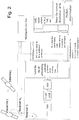
- Figure 2 illustrates the inventive multipath monitor principle by way of example.
- the multipath monitor continuously verifies that the received signal is suitable for the position determination.
- the verification is based on a monitor metric (or test metric) based on specific receiver measurements and additional calibration values.
- the monitor metric exceeds a certain threshold, the satellite or the receiver is removed from the position determination.
- a manual deselection of a receiver can be performed.
- the GNSS receiver determines the signal run time from the satellite j to the GNSS receiver i.
- the position determination can be performed simultaneously with multiple GNSS receivers (1... n i ).
- the satellite signal is typically represented by a high frequent carrier wave onto which a known (diffusion) code, which is individually set per satellite, with defined signal characteristics is modulated onto a high frequency carrier with predetermined frequency.
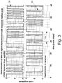
- Figure 3 illustrates the determination of signal run time by aligning received code (or GNSS code signal 30) and local code (or reference signal 31).
- received code or GNSS code signal 30
- local code or reference signal 31.
- time shift ⁇ of about 10 chips between the received code and the reference code.
- the signal characteristics of the modulated code typically are represented by a single maximum of the code autocorrelation function (ACF) for all time lags ⁇ over the code length.
- ACF code autocorrelation function
- Figure 4 illustrates the criterion for alignment of received and local code by maximum of code autocorrelation function.
- the determination of the signal run time is then based on the determination of the time difference between a zero lag ACF of the known code within the receiver (unbroken curve in Fig. 4 ) and the ACF of the received code from the satellite (broken line in Fig. 4 ). It thus shifts the local code until the ACF between the local and received code shows the maximum. However the ACF is not directly evaluated by the receiver.
- the code received from the satellite is being tracked such that it is coherent to a local code replica.
- the delay locked loop determines the code delay of the GNSS signal received from the satellite.
- the DLL provides the value of the currently determined delay which is used by the GNSS receivers code generator to keep the locally generated code matched to the received code.
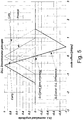
- the difference between two additional correlators is used. These additional correlators are advanced “Early” (E) and delayed, "Late” (L) relative to the punctual zero delay "Prompt” (P).
- E Errly
- L delayed, "Late”
- P punctual zero delay
- Figure 5 illustrates the code tracking loop early minus late discriminator S-curve.
- the DLL can be assisted by a phase locked loop (PLL) evaluating the phase of the high frequent satellites carrier wave and reducing the code noise.
- PLL phase locked loop
- the time shift ⁇ is a measure for the signal run time from the satellite with the time of transmission (T oT ) to the receiver where it arrived at the time of arrival (T oA ).
- the GNSS receiver thus evaluates the ACF at three correlation points: early, late, prompt.
- the chip spacing between the early and late ACF can vary. With reduced chip spacing also a reduced susceptibility to multipath errors will result.
- the real ACF deviates from the ideal one.
- the real ACF typically shows a rounded peak. Normalization of the receiver ACF can be achieved by normalizing relative to the maximum value of the real ACF prompt (P).
- the multipath monitor described herein applies additional correlators beyond those needed for the DLL code tracking.
- Figure 6 illustrates the peak of a real autocorrelation function 60 (unbroken line) in fault free conditions, as compared to an ideal autocorrelation function 61 (broken line), both normalized.
- the chip spacings (positions) P 1 through P 5 also the nominal bias b nom.1 through b nom.5 is shown.
- the prompt chip spacing P 0 is at zero chips.
- Figure 7 illustrates a code autocorrelation function with multipath (MP) component.
- the received autocorrelation function ACF of the combined signal 70 is the superposition of an error free ACF 71 and an ACF of reflected multipath signal 72.
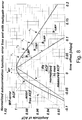
- Figure 8 illustrates the peak of code autocorrelation function under multipath influence (MP-error ACF).
- the information about the multipath error components is contained in the differences b i,MP of the (bolt unbroken) MP-error ACF curve, as compared to the (bolt broken, triangular) ideal ACF curve with multipath. Note that part of this difference is caused by the nominal bias, i.e. the difference between the (thin broken) error free ACF curve as compared to the ideal ACF curve (compare Fig. 6 ), what should be taken into account by removal of the nominal bias. In Fig. 8 , also the time shift ⁇ MP caused by multilayer signal components between the error free ACF and the MP-error ACF curve is well observable.
- the monitor test metric is built on observables stemming from a receiver's autocorrelation function at different autocorrelation chip spacings.
- the chip spacings can be arbitrary.
- the multipath signals lead to stronger deviation on the late side (on the right in Fig. 8 ) of the ACF. Therefore the additional correlator measurements primarily are taken on the late side and have to be configured according to the expectable multipath delays ⁇ MP . For a receiver with wide correlator more measurement points over a wider time offset range will be useful, compared to a narrow correlator, where a region closer around zero crossing needs to be measured.
- Figure 9 illustrates the code discriminator curve for different correlator spacings of the code-tracking.
- the normalized ACF amplitude (functional values) at the respective points are A 1 ; A 2 ; A 3 ; A 4 ; A 5 ; A 6 ; A 7 ; A 8 ... A m
- CDV 1 A 1 ⁇ A 2
- CDV 2 A 2 ⁇ A 3
- CDV 3 A 3 ⁇ A 4
- CDV n A m ⁇ 1 ⁇ A m
- a normalization with respect to nominal conditions can be performed. During this normalization at least the removal of the nominal bias b n can be performed.
- the nominal bias can be determined by a model or through measurements in fault free conditions (see Fig. 6 , where the nominal bias b nom.i is the difference between the ideal and real autocorrelation function under fault free conditions for chip positions P i ; note that when using differentiated functional values CDV i , these have a nominal bias b i,nom originating from a difference of the b nom.i values of positions P i ).
- CDV 1 , nom CDV 1 ⁇ b 1 , nom / ⁇ 1 , nom ...
- CDV m , nom CDV m ⁇ b m , nom / ⁇ m , nom
- the normalization values for each CDV are pre-determined in fault free conditions and stored in a non-volatile memory of the monitor.
- the nominal bias is composed of nominal receiver inherent correlator properties and hardware delays, as well as a satellite specific component. It is constant over longer periods of time and can be either configured as calibration value or automatically determined from periods of fault free operation.
- a change detector or monitor as applied in the present invention detects faulty measurements and removes these faulty measurements from the further processing, i.e. from the position determination.
- the applied detector performs a statistical hypothesis test for the two hypothesis:
- the test decision is performed on a test metric.
- the test metric typically shows under fault free conditions zero mean. Under influence of a fault condition the test metric shows a bias.
- test metric could be based on a first order process and changes in the mean of the test metric would be detected. This most simple case is not part of the present invention.
- Figure 10 illustrates a general monitor principle - timely (left) and statistical (right) view.
- the multipath geometry constantly varies. With this variation the angles under which the reflections enter the receiver constantly change. With the angular change also the delay of the reflected signal constantly changes. Since the combined signal within the receiver is the sum of the direct and the reflected signal, an oscillatory component will result in the combined signal. With the oscillatory component due to the multipath error a bias change is only present for certain fraction of time. With the oscillatory combined signal besides the mean, also the variance and the probability distribution shape parameters change.
- Figure 11 illustrates the oscillation of multipath error over time.
- Thermal noise can be described as white noise which follows a normal (Gaussian) distribution with zero mean (after bias removal) and thus a maximum at zero.
- the probability density function of a pure sine wave (single multipath component) has its minimum at zero and maximum probability density values at -1 and +1 and thus a completely different shape of the probability density function.
- Figure 12 illustrates the change in statistical properties of the error distribution under influence of multipath.
- the distributions' shape parameters are described with higher order moments (3 rd order - skewness, 4 th order - kurtosis).
- a test metric based on higher order test statistics can provide an increased detection capability for multipath errors.
- no increased susceptibility for pure bias errors errors of 1 st order
- the increase in the test metric will be over-proportional compared to a pure bias detector (1 st order detector).
- the detection is based on a statistical test.
- One way to detect changes in higher order statistical characteristics of the underlying signal is to collect samples over a certain measurement period and to perform statistical testing on these samples.
- the measurement principle applied herein allows to determine higher order statistics based on the multitude of instantaneous correlator measurements.
- TM 2 t k CDV 1 2 t k + CDV 2 2 t k + ... + CDV m 2 t k ⁇ var CDV 1 ... m t k
- the second order metric is proportional to the variance of the seven correlator measurement values (the second order metric can also be applied as root mean square (RMS)).
- the determination of the RMS is a second order process, leading to a chi-square test metrics.
- the second order process provides better detectability (detection to noise ratio) compared to a first order process (sum, differences, ratios or sum of abs correlator values).
- the n-th root can be applied to TMn.
- the base to calculate the exponential can be adapted. It does not need to be equal to constant "e".
- This variation provides another degree of freedom in building the test metric. It will change the tail behavior of the distribution and allows for adaptation according to actually required trade-off between false alarm and missed detection rates.
- the exponential metric contains all moments of the distribution and is capable to provide an optimal detection to noise ratio.
- the detection is performed against a predefined threshold TRH.
- the threshold is defined according to the desired false alarm and missed detection rates based on the statistical distribution.
- Figure 13 illustrates the principle of non-linear monitor test metrics.
- the threshold depends on either a maximum tolerable error or a fixed inflation compared to the nominal unfaulted measurement characteristics.
- the threshold is in all cases determined from the inverse of a distribution function. In case of derivation from fault free case - derivation for probability of false alarm (P FA ), or distribution of missed detected errors - derivation for probability of missed detection (P MD ).
- f ⁇ x 1 ⁇ ⁇ x ⁇ ⁇ 1 e ⁇ x
- THR 2 ( ⁇ 2 ) -1 (1 - P FA , f TM ) with f TM as degrees of freedom of the test metric, which is equal to n, the number of values in the test metric.
- the fourth order metric is chi-cubed distributed, according to the increase in order, etc.
- CDF ⁇ n P f TM n x n n
- the test metric calculated from the correlator measurements is compared against the predefined threshold.
- the threshold is fix for constant operational conditions (an adaptation to the operational mode can be applied).
- test metric is determined for each receiver and for each code measurement used in the system.
- the pseudorange measurement of the respective receiver with respect to the respective satellite is made unavailable.
- a receiver related monitor action will be performed if more than 2 code measurements of the respective receiver simultaneously are affected, i.e. the threshold is exceeded. Then the entire receiver is made unavailable.
- n_sat test metrics exist, which individually will be compared against its threshold.
- a second discriminator can be applied, which decides whether a satellite is made unavailable for the position determination or whether a reference receiver is to be excluded. If the threshold is exceeded for example on one or alternatively two GNSS signals or more from different satellites on the same receiver, the receiver will be considered as faulty. If the threshold is exceeded for example on two (case of train) or three (case of ground based augmentation systems for aeronautical use) receivers or more for GNSS signals from the same satellite, the satellite will be excluded.
- test metric for too many satellites n_excl,max at the respective time instance k exceeds the monitor threshold at a receiver, exclude the receiver from the position determination (if only one receiver is available, the position determination will be inhibited):
- the position determination may apply a low pass filter process to reduce the noise errors of the position determination.
- the typically applied process uses complementary filtering using the carrier measurements (Code-Carrier-Smoothing).
- the correlator measurement will not show this delayed error built-up, since no filter is applied to them.
- a low pass filter H LP can be applied to the test metric for two reasons:
- the monitor test metric can be normalized to a variance of 1 with applied filter in the fault free case by dividing through the nominal variance.
- the nominal variance depends on local environment (which doesn't change over time) and the applied filters to the test metric and thus is constant during operation.
- the compensation gain is determined from the spectral characteristics of the filter applied to the test metric: g ⁇ var unfiltered var filtered
- the variance of the filtered, error free signal is related to the variance of the unfiltered error free noise and transfer function of the low pass filter. Alternatively direct measurement in error free conditions is also possible.
- test metric is build based on the (filtered and compensated) CDV and compared against the threshold.
- a high pass filter or hold process is applied to inhibit the release of the monitor when the test metric falls below the threshold.
- the time constant of this additional hold depends on the expectable multipath characteristics. For safety critical application it is defined such that the satellite will be re-included to the position solution after the longest possible time constant of a multipath oscillation for the shortest possible object distance.
- Multiple receivers may be used in position determination to reduce noise and uncorrelated errors.
- the mean ⁇ CDV is normal fault free conditions zero.
- the determination of the co-variance between the receivers allows for direct assessment of correlation effects between the two receivers (what is the equivalent to the use of canonical correlations).
- the assessment of covariance based metrics with the open interval (-inf; inf) is advantageous over correlation (closed interval [-1; 1]) based assessment when a direct assessment of the common error is to be performed.
- correlation closed interval [-1; 1]
- the correlation will be used, as it is equivalent to the percentage of the common error in the overall error.
- the allowable degree of correlation can be determined based on the allowable degree of common error in the (averaged) position determination.
- the correlation describes the degree of common error variance.
- This process can be expanded for combined assessment of the effect from multiple receivers on a single receiver.
- the correlation of all receivers 1... i;i ⁇ o or satellites 1... j ; j ⁇ p onto one specific receiver o or satellite p can be determined as follows (again closed interval or open interval based assessments are feasible, below given equations cover the correlation based assessment.
- the covariance based assessment works in the same manner. The only difference is the use of cov instead of corr.).
- the receiver intercorrelations are calculated in accordance with Eq 18 for all receiver combinations.
- a discriminator C o,1...i describing the degree of the commonality of the error from all receivers, 1...i, onto one specific, o, can be calculated:
- C o,1...l can vary inside the interval [0; 1]. If the entire error of receiver “o” can be explained by the errors from receivers 1 ... i (fully correlated) the value of C o,1...l will be "1". C o,1...l is proportional to the percentage of common error variance.
- the multiple discriminator will directly show which receivers are affected by the common multipath error and which receivers are not.
- the number of multiple discriminators in a system consisting of I receivers is always i, what simplifies the monitor decision in case of systems with multiple receivers.
- the multiple discriminator can also be used to increase the confidence whether an error condition is local to the receiver or is due to a satellite fault. In case of a satellite fault all TM MP,I will be increased, the error is fully correlated and all multiple discriminators will deviate from zero and be larger than the maximum allowable level of common errors.
- a selection of a receiver subset (i) with minimal errors can be performed in realtime based on above given correlation / covariance assessment.
- the subset with the minimal average multiple correlation min( ⁇ (C o,i )) is then chosen from all ⁇ (C o,i+q ).
- Figure 14a and Figure 14b show an overview over the inventive monitor processing, by way of example.
Landscapes
- Engineering & Computer Science (AREA)
- Physics & Mathematics (AREA)
- General Physics & Mathematics (AREA)
- Radar, Positioning & Navigation (AREA)
- Remote Sensing (AREA)
- Computer Networks & Wireless Communication (AREA)
- Data Mining & Analysis (AREA)
- Theoretical Computer Science (AREA)
- Pure & Applied Mathematics (AREA)
- Mathematical Optimization (AREA)
- Computational Mathematics (AREA)
- Mathematical Physics (AREA)
- Mathematical Analysis (AREA)
- Evolutionary Biology (AREA)
- Bioinformatics & Computational Biology (AREA)
- Operations Research (AREA)
- Probability & Statistics with Applications (AREA)
- Bioinformatics & Cheminformatics (AREA)
- Algebra (AREA)
- Life Sciences & Earth Sciences (AREA)
- Databases & Information Systems (AREA)
- Software Systems (AREA)
- General Engineering & Computer Science (AREA)
- Signal Processing (AREA)
- Position Fixing By Use Of Radio Waves (AREA)
- Burglar Alarm Systems (AREA)
Description
- The invention relates to a method for operating a GNSS (=Global navigation satellite system) receiver,
wherein for a position determination, the GNSS receiver receives from a multitude of satellites a respective GNSS code signal,
and wherein for each signal from a satellite, the received GNSS code signal is correlated with a reference code signal generated by the GNSS receiver to obtain an autocorrelation function, wherein a multitude of function values of the autocorrelation function at different discrete chip spacings are analyzed and used in obtaining a test metric. - Such a method is known from
EP 2 793 050 B1 - GNSS (=Global navigation satellite system) receivers are used to determine the position of, for example, moving vehicles such as a plane or a ship. A number of satellites orbiting in space regularly send out GNSS code signals, which are correlated with reference signals (also called replica signals) in order to determine a time delay between the transmission and the arrival at the GNSS receiver. These time delays may be used to determine distances to the respective satellites, which move on known trajectories, so position information (such as geographical longitude, latitude and height) can be calculated.
- Ideally, the only signal path of GNSS code signals is directly from the satellite to the GNSS receiver. However, in practice, the same GNSS signal from a satellite may arrive multiple times at the GNSS receiver, since signal reflections may occur, for example, at buildings or on the ground. Indirect signal paths are longer than the direct signal path. At the receiver, a superposition of the direct signal and indirect signals is obtained, what makes determination of the time delay of the direct signal more difficult.
- In order to determine the time delay of the received (superposition) GNSS code signal and a reference signal, an autocorrelation function is calculated for different chip spacings (time shifts). If the direct signal is by far the strongest signal, then the chip spacing of the maximum of the autocorrelation function may be taken as the prompt (undelayed) chip spacing. However, multipath signal components (from indirect signals) may shift the maximum of the autocorrelation function with respect to the "true" prompt chip spacing, which can result in errors in position determination.
-
EP 2 793 050 B1 - Accordingly, the procedure of
EP 2 793 050 B1 - In case of aeronautical GBAS application, it has been proposed to account for local effects by sigma-mean monitoring based on the determination of the sample variance and mean estimations of PRC (=pseudo-range correction) quality indicators (B-values). This process takes a long time in order to collect enough samples to build the statistical estimations. This can be supported by integrating / CUSUM (=cumulative sum) methods, but still is a quite slow process (compare ref. "LAAS Sigma-Mean Monitor Analysis and Failure-Test Verification". Jiyun Lee, Sam Pullen, Gang Xie, and Per Enge. Stanford University, IEEE Transactions on Aerospace and Electronic Systems, April 2006, Volume: 42, Issue: 2).
- In train VB (=virtual balise) positioning applications, a double differencing of code phase for two GPS receivers and two satellites were proposed (compare ref. A. Neri, P.Enge et al., A METHOD FOR MULTIPATH DETECTION AND MITIGATION IN RAILWAY CONTROL APPLICATIONS, Proceedings of the 29th International Technical Meeting of the ION Satellite, Division, ION GNSS+ 2016, Portland, Oregon, September 12-16, 2016). The algorithm can detect NLOS (=non-line of sight) multipath, however only multipath differences between the two receivers are detected. Correlated multipath will not be detected
- Document
US 2006/0140254 A1 concerns the detection and removal of multi-path signals in a GNSS/CDMA receiver and discloses the features of the preamble ofclaim 1. - It is the object of present invention to provide a simple method for operating a GNSS receiver, which minimizes errors in position determination caused by multipath signal components.
- This object is achieved, in accordance with the invention and
claim 1, by a method known from the prior art and further characterized in that during analysis of the multitude of function values of the autocorrelation function, a bias removal is performed, subtracting corresponding function values of an autocorrelation function that would result from a received GNSS code signal of the satellite unaffected by multipath signal components, and that the multitude of function values contribute to the test metric in an order higher than first order. - According to the present invention, GNSS code signals which are affected by too much multipath signal components are excluded from positon determination. By this means, errors in position determination are significantly reduced. In general, a GNSS receiver has contact to more satellites than necessary for position determination. In general, four satellites are necessary for position determination (three for three space coordinates, and one for clock synchronization), but typically six or more, and often eight or more satellites have contact to the receiver. Therefore, exclusion of a few GNSS code signals from the available satellites will, most often, not hinder the position determination. On the other hand, including a GNSS code signal with significant multipath signal components may severely distort the position determination.
- In order to decide whether a GNSS signal may be used for position determination or not, a test metric (or "monitor") is obtained (or calculated), which is based on function values of the autocorrelation function. The test metric basically measures deviations of the autocorrelation function by means of the function values at the chosen ship spacings as compared to an autocorrelation function free from multipath errors. In order to increase the informative value of the test metric, the invention applies the following:
The function values are chosen asymmetrically with respect to the prompt chip spacing. The inventors found that this leads to a more reliable multipath signal component detection. Typically, the chosen asymmetry applies both to the number of functional values on both sides of the prompt chip spacing, and the chip spacing intervals covered on both sides of the prompt chip spacing. Note that the prompt chip spacing can be assumed to be at the maximum of the autocorrelation function for this purpose; its location is typically determined with an early minus late discriminator whose S-curve zero-crossing may be used for determining the prompt chip spacing. In practice, multipath signal components lead to asymmetric distortions of the autocorrelation function; this behavior can be best captured and investigated with asymmetrically chosen functional values. Note that the autocorrelation function is typically obtained (calculated) only for a limited number of discrete chip spacings (chip positions). - Further, a bias removal is performed on the function values, subtracting corresponding values of an autocorrelation function that would result from an undistorted ("direct only") GNSS code signal. This reduces or avoids contributions to the test metric resulting from the asymmetric choice of functional values as such, and may reduce noise in the test metric significantly. Typically, a removal of a "nominal bias" is done. The nominal bias corresponds to a deviation of a real autocorrelation function for a received GNSS signal unaffected by multipath signal components, as compared to an ideal (triangular) autocorrelation function. The nominal bias is typically composed of receiver inherent correlator properties and hardware delays, as well as a satellite specific component. It is in general constant over longer periods of time and can be either configured as calibration value or automatically determined from periods of fault free operation. The nominal bias may disguise (i.e. impede detection of) the multipath signal components, and taking it into account (in particular by subtracting it) in turn facilitates detection of multipath signal components accordingly. It should be noted that it is also possible to use a real autocorrelation function for a received GNSS signal unaffected by multipath signal components directly as a bias to be subtracted from the autocorrelation function obtained with the received GNSS code signal (possibly) containing multipath signal components. Typically a normalization is done in this step, too. In general, the autocorrelation function that would result from a received GNSS code signal of the satellite unaffected by multipath signal components is experimentally recorded or simulated in advance.
- Finally, the multitude of values contributes to the test metric in an order higher than the first order. The test metric (or monitor) as a function of the amount of "error" contained becomes much steeper as compared to a linear metric. This makes multipath signal components much easier to detect and to quantify, and wrong detection of multipath signal components much less likely.
- The GNSS code signal is typically a diffusion code (which is individually set for each satellite) and code modulated onto a carrier wave having a predetermined frequency.
- The position determination in accordance with the invention may comprise the determination of space coordinates, in particular three space coordinates (such as geographical longitude, geographical latitude and height above a reference ellipsoid) of the GNSS receiver from the suitable GNSS code signals, or may comprise the determination of correction data (such as clock error or differential range errors), which contains a position information about the GNSS receiver obtained from the suitable GNSS code signals, and which is provided to other GNSS receivers.
- The position determination is "instantaneous", and typically repeated consecutively, so a position information can be updated quasi-continuously. The position information as such may be derived from the propagation time of the received GNSS code signals (i.e. the shifts of the received GNSS code signals with respect to the corresponding reference signals, which indicate a distance of the GNSS receiver to the respective satellite each).
- A GNSS code signal can be considered suitable for position determination if it is sufficiently free from errors (corruption) due to multipath signal components, in particular such that the propagation time can be determined with good accuracy resp. reliability.
- The GNSS receiver comprises an antenna and a sensor. The GNSS receiver is typically installed on a vehicle (such as a train or an aircraft), but may also be stationary, or may be carried by a person.
- In a preferred variant of the inventive method, the prompt chip spacing is chosen at the maximum of the autocorrelation function. This is particularly simple. Position determination errors due to wrong prompt chip spacing are unlikely since GNSS code signals strongly affected by multipath signal components (which could shift the prompt chip spacing with respect to the maximum) have been excluded.
- In an advantageous variant, the chip spacings of the multitude of function values of the autocorrelation function are chosen predominantly, preferably completely, on the late side with respect to the prompt chip spacing. This has shown particularly reliable detection of multipath signal components. Signal paths including a reflection are longer than the direct signal path, and therefore will appear on the late side. With this variant, this asymmetry in the autocorrelation function will be better covered.
- Further preferred is a variant wherein at least 3, preferably at least 6, most preferably at least 8, functional values contribute to the test metric. This increases the reliability of detection of multipath signal components.
- In an advantageous variant, during analysis of the functional values, pairwise differences of functional values with successive chip spacings are calculated, and these differences are used to calculate the test metric. This has been found to reduce signal noise in the test metric in many situations. Bias removal may be done on the functional values before calculating the difference, or may be done on the differences. Alternatively, the functional values themselves (after bias removal) may be directly used to calculate the test metric.
- Further preferred is a variant in which the bias removal encompasses a normalization and/or variance scaling. This may reduce noise and makes the contribution of the various function values comparable.
- Particularly preferred is a variant wherein the functional values contribute to the test metric in second or higher order, in particular wherein the functional values contribute to the test metric exponentially. This makes multipath signal components even easier to detect. It is also possible that the functional values contribute in third order (cubic), or fourth order, or even higher. For example, the test metric may be calculated as a root mean square value. Preferred are even orders. In general, and in particular in case of odd orders, absolute values of contributions to the test metric should be calculated.
- A particularly advantageous variant provides that in said decision the test metric is used such that in case the test metric is larger than a critical value, the received GNSS code signal is considered unsuitable for position determination. This is a particularly simple procedure. If necessary, an absolute value may be generated before doing the comparison with the critical value. Alternatively, a range or ranges of values may be defined for the test metric, and a received GNSS code signal is considered unsuitable for position determination if its test metric is outside said ("allowed") range or ranges.
- Further preferred is a variant which is characterized in
that position determinations are done repeatedly,
that carrier waves carrying the GNSS code signals undergo a low pass filtering, and that in case a received GNSS code signal of a satellite has been found unsuitable for position determination using the test metric, a number of subsequent received GNSS code signals of the same satellite will be considered as unsuitable for position determination, too, regardless of obtained test metrics for these subsequent GNSS code signals. The low pass filtering of the carrier wave reduces noise. In this variant, the test metric is not low pass filtered or low pass filtered with a time constant shorter than the time constant of the low pass filtering of the carrier wave, resulting in a "non-coherent" test metric. The detected multipath corruption affects the position determination with delay, and the blocking of the number of subsequent GNSS code signals avoids entry of the multipath corruption into the position determination. The number of subsequent received GNSS code signals depends on the time constant of the low pass filtering (or smoothing) of the carrier wave (or on the difference of time constants, in case the test metric is also low pass filtered). Note that in each repetition of position determination, newly received GNSS code signals are used. - Another variant is characterized in
that position determinations are done repeatedly,
that carrier waves carrying the GNSS code signals undergo a low pass filtering, and that said low pass filtering is reproduced in the test metric. The low pass filtering of the carrier wave reduces noise. The low pass filtering of the carrier wave and the reproduced low pass filtering of the test metric have basically the same signal properties in terms of spectral density and timely behavior. The low pass filter applied to the test metric will in many cases not be identical to the low pass filter used in the processing of the GNSS code signal in the receiver processing for position determination. In this situation, the low pass filter applied to the test metric models the relevant signal characteristics of the filter applied to the GNSS code signal processing. Thus a "coherent" test metric can be obtained, despite of the delayed arrival of the multipath corruption at position determination. - A highly preferred variant provides
that a number N of GNSS receivers are operated simultaneously, with N≥2, wherein the different GNSS receivers receive GNSS code signals from a number J of satellites, with J≥2,
and that the decision whether a particular GNSS code signal from a particular satellite received at a particular GNSS receiver is suitable for a position determination or unsuitable for a position determination due to multipath signal components is not only depending on the test metric of this particular GNSS code signal, but also depending on the test metrics of GNSS code signals received by the other GNSS receivers and/or from the other satellites. By operating multiple GNSS receivers, the position determination may be further improved in accuracy. Non-common errors at different GNSS receivers may be reduced, for example by averaging obtained signal information. At least some of the GNSS code signals received at the N different GNSS receivers originate from the same J satellites. By analyzing other test metrics than the one of the particular GNSS code signal, defects at receivers or satellites may be found which corrupt position determination. In this variant, in addition to a direct control of the test metric of a particular GNSS code signal, at least one additional discriminator is applied in order to find out whether the particular GNSS code signal may be corrupted (due to multipath signal components or other causes). This increases accuracy and reliability of the position determination. In general, the additional discriminator is applied to all received GNSS code signals. Typically, J≥4 and N≥4. Of particular importance are the test metrics of GNSS code signals received by the other GNSS receivers and/or from the other satellites which exceed a threshold, indicating a multipath error; these are preferably used (analyzed) in this variant. - In a further development of this variant, in case covariance of test metrics from different GNSS receivers belonging to received GNSS code signals from the same satellite exceeds a threshold, all received GNSS code signals from that satellite are considered unsuitable for position determination. In this case, a defect at the particular satellite is likely, and its GNSS code signals are no more trustworthy. Their exclusion improves the position determination reliability. Note that a covariance is typically used normalized, i.e. as a correlation. The covariance of the test metrics may be bi-variate or multi-variate. In particular, a second discriminator, describing the degree of the commonality of the error from all receivers, 1... N, onto one specific receiver, o, is applied. In environments with N>3 the use of this additional discriminator reduces the number of tests to be performed to identify a faulty receiver down to N tests compared to (N2-N)/2. If the test metric for a particular satellite received at different GNSS receivers corresponds to a multi-variate covariance determined for more than 2 receivers, the multiple discriminator can be used to increase the confidence whether an error condition is local to the receiver or is due to a satellite fault.
- In another further development, in case covariance of test metrics from the same GNSS receiver belonging to GNSS code signals from different satellites exceeds a threshold, all received GNSS code signals at that GNSS receiver are considered unsuitable for position determination. In this case, a defect at the particular GNSS receiver is likely, and GNSS code signals received there are no more trustworthy. Their exclusion improves the position determination reliability. The covariance of the test metrics may be bi-variate or multi-variate.
- In another preferred further development, in case for a particular GNSS receiver, a critical fraction of received GNSS code signals is considered unsuitable due to the test metric of the respective received GNSS code signal in each case, then all GNSS code signals received at the particular GNSS receiver are considered unsuitable for position determination. In this case, a defect at the particular GNSS receiver is likely, and GNSS code signals received there are no more trustworthy. Their exclusion improves the position determination reliability. If J≥4, then the critical fraction typically corresponds to 2 unsuitable GNSS code signals.
- A further development provides that in case for a particular satellite, a critical fraction of GNSS code signals from the particular satellite received at different GNSS receivers is considered unsuitable due to the test metric of the respective received GNSS code signal in each case, then all GNSS code signals from that satellite are considered unsuitable for position determination. In this case, a defect at the particular satellite is likely, and its GNSS code signals are no more trustworthy. Their exclusion improves the position determination reliability. If N≥4, then the critical fraction typically corresponds to 2 unsuitable GNSS code signals.
- In an advantageous variant, one or a plurality of GNSS receivers is placed on a train, in particular a running train. GNSS receivers on trains are likely to be affected by significant multipath signal components, since trains often travel in urban or geographical canyons, where signal reflections are likely. Here the invention may be particularly useful in increasing the reliability of position determination.
- Also within the scope of the present invention, and according to
claim 17, is a GNSS receiver or a set of GNSS receivers, adapted for performing an inventive, above described method. - Further advantages can be extracted from the description and the enclosed drawing. The features mentioned above and below can be used in accordance with the invention either individually or collectively in any combination. The embodiments mentioned are not to be understood as exhaustive enumeration but rather have exemplary character for the description of the invention.
- The invention is shown in the drawing.
- Fig. 1
- shows a schematic illustration of multipath as combined reception of direct and reflected signal;
- Fig. 2
- shows a schematic illustration of the inventive multipath monitor principle;
- Fig. 3
- shows a schematic illustration of the determination of signal run time by aligning received and local code;
- Fig. 4
- shows a schematic illustration of the criterion for alignment of received and local code by maximum of code autocorrelation function;
- Fig. 5
- shows a schematic illustration of a code tracking loop early minus late discriminator S-curve;
- Fig. 6
- shows a schematic illustration of peak of autocorrelator function in fault free conditions;
- Fig. 7
- shows a schematic illustration of a code autocorrelation function with multipath component;
- Fig. 8
- shows a schematic illustration of a peak code autocorrelation function under multipath influence;
- Fig. 9
- shows a schematic illustration of a code discriminator curve for different correlator spacings of the code-tracking;
- Fig. 10
- shows a schematic illustration of the general monitor principle, timely (left) and statistical (right) view;
- Fig. 11
- shows a schematic diagram of an oscillation of multipath error over time;
- Fig. 12
- shows a schematic illustration of change in statistical properties of the error distribution under influence of multipath;
- Fig. 13
- shows a schematic illustration of the principle of non-linear monitor test metrics;
- Fig. 14a-14b
- shows a schematic illustration of the inventive monitor processing overview by way of example.
- Local errors can result from the reception of reflected signals (multipath) entering the GNSS receiver with a delay compared to the direct signal. Multipath is known as combined signal reception of the direct line-of-sight ranging signal and one or more reflected ranging signals of the same satellite, which are travelling a longer path.
-
Figure 1 shows multipath as combined reception of direct and reflected signals. Asatellite 10 sends out asignal 11. At theGNSS receiver 12, a direct signal (or signal component) 13, a signal (or signal component) 14 reflected on theground 15, and a signal (or signal component) 16 reflected by areflector 17, here a vertical obstacle such as a building, arrive and superimpose, so the total received GNSS code signal contains multipath signal components. The GNSS receiver may be placed on a vehicle, such as a train (not shown). - Local uncorrelated multipath (single satellite on single antenna) or correlated multipath (single satellite on more than one antenna) are part of the considerations. In addition, Non-Line-Of-Sight (NLOS) multipath is characterized by the absence of the direct path (masked signal) and presence of multipath signals.
- The reception of multipath affected GNSS signals due reflections in the local environment of the GNSS antenna lead to very high code measurement errors and finally errors of the position determination. In GNSS systems applying or generating differential corrections for the position determination process (GBAS, SBAS, VB) multipath is the largest error source.
- The dominant GNSS threat for railway applications is multipath, which largely depends on the local environment where trains are travelling. In particular the urban railway multipath environment is harsher compared to other applications because multipath reflection sources such as but not limited to reflections from metal objects, buildings and ground reflections, may cause significant pseudorange errors that transform into the position solution.
- In safety critical GNSS applications it is desirable to detect multipath in order to avoid usage of affected measurements in the position error determination. Otherwise erroneous position solutions will result.
- Since other error sources like satellite faults (such as imperfect code generation within the satellite) can show up with similar effects, it is desirable to distinguish multipath from other errors to apply the correct actions (special relevance for GBAS/SBAS, VB).
- For the aeronautical GBAS application the invention proposes multiple GNSS antennas distributed on the ground, connected each to resp. being part of a GNSS receiver or sensor, which in turn outputs various measurement data in a realtime behaviour such as once or twice per second. The measurement data may include relevant GNSS measurements such as correlator amplitude outputs, pseudorange measurement carrier phase measurement, timing measurements or other ranging measurements. The invention proposes also one or multiple processing devices that are connected to resp. included in the GNSS receivers and are able to run the algorithms and methods described below.
- For the train VB application, the invention proposes multiple GNSS antennas distributed on the train, connected each to resp. being part of a GNSS receiver or sensor, which in turn outputs various measurement data in a realtime behaviour such as once or twice per second. The measurement data may include relevant GNSS measurements such as correlator amplitude outputs, pseudorange measurement carrier phase measurement, timing measurements or other ranging measurements. The invention may include also other sensors such as odometer, radar or inertial sensors that are also delivering measurement data. In addition the invention proposes one or multiple processing devices that are connected to resp. included in the GNSS receivers and the sensor devices and are able to run the algorithms and methods described below
- The methodology proposes a multipath monitor mean to deselect receivers/antennas or corresponding GNSS code signals.
- The multipath monitor can be applied to GNSS in general. The monitor can perform various executive actions: inflation of integrity parameters, set a mask for elevation-azimuth range, exclusion of satellite, exclusion of receiver.
- The receiver/antenna deselector preferably additionally allows to manually disable individual receivers in cases where multiple receivers are installed.
-
Figure 2 illustrates the inventive multipath monitor principle by way of example. - The multipath monitor continuously verifies that the received signal is suitable for the position determination. The verification is based on a monitor metric (or test metric) based on specific receiver measurements and additional calibration values. In case the monitor metric exceeds a certain threshold, the satellite or the receiver is removed from the position determination. In addition a manual deselection of a receiver can be performed.
- During the position determination the GNSS receiver determines the signal run time from the satellite j to the GNSS receiver i. The position determination can be performed simultaneously with multiple GNSS receivers (1... ni).
- The satellite signal is typically represented by a high frequent carrier wave onto which a known (diffusion) code, which is individually set per satellite, with defined signal characteristics is modulated onto a high frequency carrier with predetermined frequency.
-
Figure 3 illustrates the determination of signal run time by aligning received code (or GNSS code signal 30) and local code (or reference signal 31). In the example shown, there is a time shift Δτ of about 10 chips between the received code and the reference code. - The signal characteristics of the modulated code typically are represented by a single maximum of the code autocorrelation function (ACF) for all time lags τ over the code length.
-
Figure 4 illustrates the criterion for alignment of received and local code by maximum of code autocorrelation function. - The determination of the signal run time is then based on the determination of the time difference between a zero lag ACF of the known code within the receiver (unbroken curve in
Fig. 4 ) and the ACF of the received code from the satellite (broken line inFig. 4 ). It thus shifts the local code until the ACF between the local and received code shows the maximum. However the ACF is not directly evaluated by the receiver. - To determine the signal run time the code received from the satellite is being tracked such that it is coherent to a local code replica. This is achieved by a signal tracking loop, the delay locked loop (DLL), which determines the code delay of the GNSS signal received from the satellite. The DLL provides the value of the currently determined delay which is used by the GNSS receivers code generator to keep the locally generated code matched to the received code. Within the DLL the difference between two additional correlators is used. These additional correlators are advanced "Early" (E) and delayed, "Late" (L) relative to the punctual zero delay "Prompt" (P). As a result of the differencing the S-curve is obtained and the DLL maintains zero crossing of the S-curve.
-
Figure 5 illustrates the code tracking loop early minus late discriminator S-curve. - The DLL can be assisted by a phase locked loop (PLL) evaluating the phase of the high frequent satellites carrier wave and reducing the code noise.
- The time shift Δτ is a measure for the signal run time from the satellite with the time of transmission (ToT) to the receiver where it arrived at the time of arrival (ToA). The signal run time in turn is a measure for the distance R between the satellite and the receiver. Both are related to each other by the speed of light c by the following equation:

- In aforementioned description the clock differences between the clock of the GNSS receiver and the satellite are not considered.
- Furthermore error sources like signal delays due refraction in ionosphere and troposphere as well as errors in the satellite position and imperfect code generation by the satellite and errors resulting in the vicinity of the GNSS receiver are not considered.
- The GNSS receiver thus evaluates the ACF at three correlation points: early, late, prompt.
- The chip spacing between the early and late ACF can vary. With reduced chip spacing also a reduced susceptibility to multipath errors will result.
- Due to filters typically applied in the GNSS receiver at different stages of its internal signal processing, especially due to pre-correlation filtering, the real ACF deviates from the ideal one. The real ACF typically shows a rounded peak. Normalization of the receiver ACF can be achieved by normalizing relative to the maximum value of the real ACF prompt (P).
- The multipath monitor described herein applies additional correlators beyond those needed for the DLL code tracking.
- These additional ACF measurements can show a nominal bias under fault free conditions due to the aforementioned normalization. Additional nominal biases can result from typical imperfections in the satellites code generation, which are typical to its actual design and do not represent a satellite fault.
-
Figure 6 illustrates the peak of a real autocorrelation function 60 (unbroken line) in fault free conditions, as compared to an ideal autocorrelation function 61 (broken line), both normalized. For the chip spacings (positions) P1 through P5, also the nominal bias bnom.1 through bnom.5 is shown. The prompt chip spacing P0 is at zero chips. - With these additional correlators at each time instance of the position determination a multitude of function values (in
Fig. 6 at P1 through P5) of the autocorrelation function in the GNSS receiver during determination of the satellite signal run time are taken. - Under presence of multipath the ACF within the receiver will be represented by the complex sum of the fault free / direct signal and the reflected multipath signal. Due to the multipath signal the ACF in the receiver will be deformed and the peak deviates from τ = 0 by τ = τMP.
- Due to this deformation the measurements taken from the additional correlator chip spacings will deviate from their nominal range of values.
-
Figure 7 illustrates a code autocorrelation function with multipath (MP) component. The received autocorrelation function ACF of the combinedsignal 70 is the superposition of an errorfree ACF 71 and an ACF of reflectedmultipath signal 72. -
Figure 8 illustrates the peak of code autocorrelation function under multipath influence (MP-error ACF). The information about the multipath error components is contained in the differences bi,MP of the (bolt unbroken) MP-error ACF curve, as compared to the (bolt broken, triangular) ideal ACF curve with multipath. Note that part of this difference is caused by the nominal bias, i.e. the difference between the (thin broken) error free ACF curve as compared to the ideal ACF curve (compareFig. 6 ), what should be taken into account by removal of the nominal bias. InFig. 8 , also the time shift τMP caused by multilayer signal components between the error free ACF and the MP-error ACF curve is well observable. - The monitor test metric is built on observables stemming from a receiver's autocorrelation function at different autocorrelation chip spacings.
- The examples are valid for a E-L (=early-late) coherent DLL type with 0.1 chip spacing for DLL tracking loop. However, the methodology works also with other receivers.
- The chip spacings can be arbitrary. The multipath signals lead to stronger deviation on the late side (on the right in
Fig. 8 ) of the ACF. Therefore the additional correlator measurements primarily are taken on the late side and have to be configured according to the expectable multipath delays τMP. For a receiver with wide correlator more measurement points over a wider time offset range will be useful, compared to a narrow correlator, where a region closer around zero crossing needs to be measured. -
Figure 9 illustrates the code discriminator curve for different correlator spacings of the code-tracking. - In the investigated case of a GNSS receiver with a chip spacing of 0.1 chips, eight correlator points with the following chip spacing were used (fractions of the GPS L1 C/A code length):
P1 = -0.5; P2 = -0.025; P3 = 0; P4 = +0.025; P5 = +0.05; P6 = +0.075; P7 = +0.1; P8 = +0.125. In the general case n-measurements P1 ... Pn are taken. - The normalized ACF amplitude (functional values) at the respective points are A1; A2; A3; A4; A5; A6; A7; A8 ... Am
In the further processing these can either directly be used as is or adjacent correlator measurements can also be differentiated in direction of increasing chip length, resulting in:
- A normalization with respect to nominal conditions can be performed. During this normalization at least the removal of the nominal bias bn can be performed. The nominal bias can be determined by a model or through measurements in fault free conditions (see
Fig. 6 , where the nominal bias bnom.i is the difference between the ideal and real autocorrelation function under fault free conditions for chip positions Pi; note that when using differentiated functional values CDVi, these have a nominal bias bi,nom originating from a difference of the bnom.i values of positions Pi). - Additionally a variance scaling by the nominal variance σm 2 can be performed such that the CDVnom,1...m are zero mean and a variance of one results in fault free conditions.

- The normalization values for each CDV are pre-determined in fault free conditions and stored in a non-volatile memory of the monitor.
- The nominal bias is composed of nominal receiver inherent correlator properties and hardware delays, as well as a satellite specific component. It is constant over longer periods of time and can be either configured as calibration value or automatically determined from periods of fault free operation.
- A change detector or monitor as applied in the present invention, and applicable in safety critical applications, detects faulty measurements and removes these faulty measurements from the further processing, i.e. from the position determination.
- The applied detector performs a statistical hypothesis test for the two hypothesis:
- H0: the measurement is fault free
- H1: the measurement is faulty
- The test decision is performed on a test metric. The test metric typically shows under fault free conditions zero mean. Under influence of a fault condition the test metric shows a bias.
- In the most simple case, the test metric could be based on a first order process and changes in the mean of the test metric would be detected. This most simple case is not part of the present invention.
-
Figure 10 illustrates a general monitor principle - timely (left) and statistical (right) view. - Due to the satellite movement and potential movements of the receiver and the reflector, the multipath geometry constantly varies. With this variation the angles under which the reflections enter the receiver constantly change. With the angular change also the delay of the reflected signal constantly changes. Since the combined signal within the receiver is the sum of the direct and the reflected signal, an oscillatory component will result in the combined signal. With the oscillatory component due to the multipath error a bias change is only present for certain fraction of time. With the oscillatory combined signal besides the mean, also the variance and the probability distribution shape parameters change.
-
Figure 11 illustrates the oscillation of multipath error over time. - In fault free conditions the ACF values vary around their mean due to thermal noise.
- Thermal noise can be described as white noise which follows a normal (Gaussian) distribution with zero mean (after bias removal) and thus a maximum at zero.
- The probability density function of a pure sine wave (single multipath component) has its minimum at zero and maximum probability density values at -1 and +1 and thus a completely different shape of the probability density function.
- With the multipath component the error distribution of the signal will change.
-
Figure 12 illustrates the change in statistical properties of the error distribution under influence of multipath. - The distributions' shape parameters are described with higher order moments (3rd order - skewness, 4th order - kurtosis).
- In general the n-th statistical moment is defined as:

- For zero mean distributed values, like white noise, the expectation value is zero.
- Due to the change in the statistical properties of a multipath affected signal the higher order moments will increase over those for white noise.
- Thus, and according to the invention, a test metric based on higher order test statistics can provide an increased detection capability for multipath errors. In parallel no increased susceptibility for pure bias errors (errors of 1st order) will result. Moreover, the increase in the test metric will be over-proportional compared to a pure bias detector (1st order detector).
- Typically such pure bias errors result from errors in the satellites signal generation, like imperfect code.
- Especially in multi-GNSS receiver environments it is desirable to separate both types of errors.
- The detection is based on a statistical test. One way to detect changes in higher order statistical characteristics of the underlying signal (variance, skewness, kurtosis) is to collect samples over a certain measurement period and to perform statistical testing on these samples.
- The measurement principle applied herein allows to determine higher order statistics based on the multitude of instantaneous correlator measurements.
- The second order test metric TM2 of the seven differentiated correlator measurements is determined as follows:

- The second order metric is proportional to the variance of the seven correlator measurement values (the second order metric can also be applied as root mean square (RMS)).
- The determination of the RMS is a second order process, leading to a chi-square test metrics.
- The second order process provides better detectability (detection to noise ratio) compared to a first order process (sum, differences, ratios or sum of abs correlator values).
- Higher order processes can also be applied - polynoms of third, fourth and higher order as well as exponential process can be applied.
- A further increase is feasible by using higher orders.
- The n-th order test metric TMn built from the seven differentiated correlator measurements is determined accordingly:

- In equivalence to the 2nd-order process, the n-th root can be applied to TMn.
- For polynomial test metrics even order polynoms are preferable, since no negative values will result - the test statistics is then single sided.
- The same applies for exponential test metrics.
- The exponential metric can be built as follows:

- The base to calculate the exponential can be adapted. It does not need to be equal to constant "e".
- It will therefore be denoted as "lambda".
- This variation provides another degree of freedom in building the test metric. It will change the tail behavior of the distribution and allows for adaptation according to actually required trade-off between false alarm and missed detection rates.
- The exponential metric is related to higher order polynomials since the exponential function can be expressed by a Taylor-polynomial:

- Thus the exponential metric contains all moments of the distribution and is capable to provide an optimal detection to noise ratio.
- The detection is performed against a predefined threshold TRH.
- The threshold is defined according to the desired false alarm and missed detection rates based on the statistical distribution.
-
Figure 13 illustrates the principle of non-linear monitor test metrics. - The threshold depends on either a maximum tolerable error or a fixed inflation compared to the nominal unfaulted measurement characteristics.
- The threshold is in all cases determined from the inverse of a distribution function. In case of derivation from fault free case - derivation for probability of false alarm (PFA), or distribution of missed detected errors - derivation for probability of missed detection (PMD).
- In case of PFA based derivation the general form is:

- 1st order:

- For the expression of higher orders it is necessary to express the distributions using the gamma function:

- The gamma distribution is:

- 2nd order metric is chi-square distributed: THR 2 = (χ 2)-1 (1 - PFA, fTM ) with fTM as degrees of freedom of the test metric, which is equal to n, the number of values in the test metric.
- The chi-square distribution is related to the gamma distribution as:


- The fourth order metric is chi-cubed distributed, according to the increase in order, etc.

- The exponential distribution is expressed with the parameter lambda used to define the trade-off between Pmd and PFA (with the base to relate lambda ∼ fTM) :


- The test metric calculated from the correlator measurements is compared against the predefined threshold. The threshold is fix for constant operational conditions (an adaptation to the operational mode can be applied).
- The test metric is determined for each receiver and for each code measurement used in the system.
- Thus in case with four reference antennas/receivers and nj satellites being tracked, 4 x nj measurements exist, which individually will be compared against its threshold.
- When the threshold is exceeded, the pseudorange measurement of the respective receiver with respect to the respective satellite is made unavailable.
- Further, in the simplest case, a receiver related monitor action will be performed if more than 2 code measurements of the respective receiver simultaneously are affected, i.e. the threshold is exceeded. Then the entire receiver is made unavailable.
- When the test metric TM for the respective satellite j measured with receiver i at respective time instance k exceeds the threshold THR, the code measurement for the respective satellite is excluded from the position determination and an exclusion counter N_excl is counted up:
 If
 TM > THR
 then
 exclude code_measurement(j, i, k)
 and
 n_excl = n_excl + 1
 If
 n_excl > n_excl,max
 then
 exclude i
- Monitor noise can be reduced by low pass filtering: This increases the detectability of multipath error conditions: The time constant and filter characteristics need to be chosen to be compliant with the range measurement processing. The filter characteristics need to be defined such that the filter applied to the test metric shows the same timely and spectral characteristics compared to the filter applied to the code measurements used in the position determination (i.e. impulse response is identical). In case of safety critical aeronautical applications 0.30 s and 100 s smoothing are applied to a 1st order low pass filter. This ensures coherency with unsmoothed and code-carrier smoothed pseudorange errors.
- Monitor can react before the position determination is faulty: If the monitor is made non-coherent (for instance by smaller time constant of the test metric filtering, compared to the one of the pseudorange smoothing filter), a 'look ahead' monitor characteristics can be achieved - it can be made faster. If done so, the monitor is no more coherent with the error and thus an additional high pass filter or a hold back is to be applied to ensure the test metric remains high for the longest multipath autocorrelation time.


- With systems providing differential corrections to GNSS satellites a mean at the ground equipment to remove a single antenna from calculation of the averaged correction information (pseudo-range correction PRC & range rate correction RRC) or position calculation as well as from common clock determination may be provided.
- Such a mean can be a hardware (HW) switch or a software (SW) mean like button in a graphical user interface.
- As a reaction, the respective antenna is excluded from calculation of correction information and the clock determination.
- The activation of the de-selection may be annunciated by visual means (like a LED).
- The operational mode is adapted depending on the number of installed GNSS reference antennas. Examples :
- ∘ In case of aeronautical GBAS operation with three ground reference antennas in support of CAT III operations with deselection of one antenna the mode will be adapted from active CAT III support to CAT I (or II) support.
- ∘ In case of train operation with full supervised mode with the deselection of an antenna the active mode is reduced to a degraded mode such as staff responsible mode.
- No activation of the maintenance mode (incl. shutdown of the GBAS data broadcast) is performed.
- Annunciation to ATC operator or driver is only performed in case of degradation of the mode, so that it is feasible to continue normal operation if hot spare reference antennas are available.
- Without hot spare antennas the noise in the system will slightly increase and the correction information will be slightly noisier what normally reduces the continuity. However, with sufficiently high nominal ground performance even after de-selection of one antenna the remaining number of active reference antennas is high enough to achieve the required performance (only redundancy is affected).
Claims (17)
- A method for operating a GNSS, Global Navigation Satellite System, receiver (12), wherein for a position determination, the GNSS receiver (12) receives from a multitude of satellites (10) a respective GNSS code signal (30), and wherein for each signal (11) from a satellite (10), the received GNSS code signal (30) is correlated with a reference code signal (31) generated by the GNSS receiver (12) to obtain an autocorrelation function (70), wherein a multitude of function values (Ai) of the autocorrelation function (70) at different discrete chip spacings (Pi) are analyzed and used in obtaining a test metric (TM),
wherein using the test metric (TM), a decision is made whether the received GNSS code signal (30) is suitable for a position determination or unsuitable for a position determination due to multipath signal components,
wherein a position determination of the GNSS receiver (12) is made based on the received GNSS code signals (30) from the multitude of satellites (10), with received GNSS code signals (30) considered unsuitable for position determination being excluded from the position determination,
wherein the chip spacings (Pi) of the multitude of function values (Ai) of the autocorrelation function (70) are chosen asymmetrically with respect to a prompt chip spacing (P0),
characterized in
that during analysis of the multitude of function values (Ai) of the autocorrelation function (70), a bias removal is performed, subtracting corresponding function values of an autocorrelation function (60) that would result from a received GNSS code signal (30) of the satellite (10) unaffected by multipath signal components,
and that the multitude of function values (Ai) contribute to the test metric (TM) in an order higher than first order. - Method according to claim 1, characterized in that the prompt chip spacing (P0) is chosen at the maximum of the autocorrelation function (70).
- Method according to one of the preceding claims, characterized in that the chip spacings (Pi) of the multitude of function values (Ai) of the autocorrelation function (70) are chosen predominantly, preferably completely, on the late side with respect to the prompt chip spacing (P0).
- Method according to one of the preceding claims, characterized in that at least 3, preferably at least 6, most preferably at least 8, functional values (Ai) contribute to the test metric (TM).
- Method according to one of the preceding claims, characterized in that during analysis of the functional values (Ai), pairwise differences (CDVi) of functional values (Ai) with successive chip spacings (Pi) are calculated, and these differences (CDVi) are used to calculate the test metric (TM).
- Method according to one of the preceding claims, characterized in that the bias removal encompasses a normalization and/or variance scaling.
- Method according to one of the preceding claims, characterized in that the functional values (Ai) contribute to the test metric (TM) in second or higher order, in particular wherein the functional values (Ai) contribute to the test metric (TM) exponentially.
- Method according to one of the preceding claims, characterized in that in said decision the test metric (TM) is used such that in case the test metric (TM) is larger than a critical value (TRH), the received GNSS code signal (30) is considered unsuitable for position determination.
- Method according to one of the claims 1 through 8, characterized in that position determinations are done repeatedly,
that carrier waves carrying the GNSS code signals (30) undergo a low pass filtering,
and that in case a received GNSS code signal (30) of a satellite (10) has been found unsuitable for position determination using the test metric (TM), a number of subsequent received GNSS code signals (30) of the same satellite (10) will be considered as unsuitable for position determination, too, regardless of obtained test metrics (TM) for these subsequent GNSS code signals (30). - Method according to one of the claims 1 through 8, characterized in that position determinations are done repeatedly,
that carrier waves carrying the GNSS code signals (30) undergo a low pass filtering,
and that said low pass filtering is reproduced in the test metric (TM). - Method according to one of the preceding claims, characterized in that a number N of GNSS receivers (12) are operated simultaneously, with N≥2, wherein the different GNSS receivers (12) receive GNSS code signals (30) from a number J of satellites (10), with J≥2,
and that the decision whether a particular GNSS code signal (30) from a particular satellite (10) received at a particular GNSS receiver (12) is suitable for a position determination or unsuitable for a position determination due to multipath signal components is not only depending on the test metric (TM) of this particular GNSS code signal (30), but also depending on the test metrics (TM) of GNSS code signals (30) received by the other GNSS receivers (12) and/or from the other satellites (10). - Method according to claim 11, characterized in that in case covariance of test metrics (TM) from different GNSS receivers (12) belonging to received GNSS code signals (30) from the same satellite (10) exceeds a threshold, all received GNSS code signals (30) from that satellite (10) are considered unsuitable for position determination.
- Method according to claim 11 or 12, characterized in that in case covariance of test metrics (TM) from the same GNSS receiver (12) belonging to GNSS code signals (30) from different satellites (10) exceeds a threshold, all received GNSS code signals (30) at that GNSS receiver (12) are considered unsuitable for position determination.
- Method according to one of the claims 11 through 13, characterized in that in case for a particular GNSS receiver (12), a critical fraction of received GNSS code signals (30) is considered unsuitable due to the test metric (TM) of the respective received GNSS code signal (30) in each case, then all GNSS code signals (30) received at the particular GNSS receiver (12) are considered unsuitable for position determination.
- Method according to one of the claims 11 through 14, characterized in that in case for a particular satellite (10), a critical fraction of GNSS code signals (30) from the particular satellite (10) received at different GNSS receivers (12) is considered unsuitable due to the test metric (TM) of the respective received GNSS code signal (30) in each case, then all GNSS code signals (30) from that satellite (10) are considered unsuitable for position determination.
- Method according to one of the preceding claims, characterized in that one or plurality of GNSS receivers (12) is placed on a train, in particular a running train.
- A GNSS receiver (12) or a set of GNSS receivers (12), adapted for performing a method according to one of the claims 1 through 16.
Priority Applications (11)
| Application Number | Priority Date | Filing Date | Title |
|---|---|---|---|
| EP17184536.5A EP3438700B1 (en) | 2017-08-02 | 2017-08-02 | Method for operating a gnss receiver, with gnss signal deselection |
| SI201730633T SI3438700T1 (en) | 2017-08-02 | 2017-08-02 | Method for operating a gnss receiver, with gnss signal deselection |
| ES17184536T ES2853199T3 (en) | 2017-08-02 | 2017-08-02 | Method of operating a GNSS receiver, with GNSS signal deselection |
| RS20210179A RS61583B1 (en) | 2017-08-02 | 2017-08-02 | Method for operating a gnss receiver, with gnss signal deselection |
| PL17184536T PL3438700T3 (en) | 2017-08-02 | 2017-08-02 | Method for operating a gnss receiver, with gnss signal deselection |
| PT171845365T PT3438700T (en) | 2017-08-02 | 2017-08-02 | Method for operating a gnss receiver, with gnss signal deselection |
| DK17184536.5T DK3438700T3 (en) | 2017-08-02 | 2017-08-02 | PROCEDURE FOR OPERATING A GNSS RECEIVER, WITH GNSS SIGNAL SELECTION |
| LTEP17184536.5T LT3438700T (en) | 2017-08-02 | 2017-08-02 | Method for operating a gnss receiver, with gnss signal deselection |
| CA3012499A CA3012499C (en) | 2017-08-02 | 2018-07-26 | Method for operating a gnss receiver, with gnss signal deselection |
| US16/051,705 US10324194B2 (en) | 2017-08-02 | 2018-08-01 | Method for operating a GNSS receiver, with GNSS signal deselection |
| HRP20210224TT HRP20210224T1 (en) | 2017-08-02 | 2021-02-09 | Method for operating a gnss receiver, with gnss signal deselection |
Applications Claiming Priority (1)
| Application Number | Priority Date | Filing Date | Title |
|---|---|---|---|
| EP17184536.5A EP3438700B1 (en) | 2017-08-02 | 2017-08-02 | Method for operating a gnss receiver, with gnss signal deselection |
Publications (2)
| Publication Number | Publication Date |
|---|---|
| EP3438700A1 EP3438700A1 (en) | 2019-02-06 |
| EP3438700B1 true EP3438700B1 (en) | 2020-11-18 |
Family
ID=59520819
Family Applications (1)
| Application Number | Title | Priority Date | Filing Date |
|---|---|---|---|
| EP17184536.5A Active EP3438700B1 (en) | 2017-08-02 | 2017-08-02 | Method for operating a gnss receiver, with gnss signal deselection |
Country Status (11)
| Country | Link |
|---|---|
| US (1) | US10324194B2 (en) |
| EP (1) | EP3438700B1 (en) |
| CA (1) | CA3012499C (en) |
| DK (1) | DK3438700T3 (en) |
| ES (1) | ES2853199T3 (en) |
| HR (1) | HRP20210224T1 (en) |
| LT (1) | LT3438700T (en) |
| PL (1) | PL3438700T3 (en) |
| PT (1) | PT3438700T (en) |
| RS (1) | RS61583B1 (en) |
| SI (1) | SI3438700T1 (en) |
Families Citing this family (17)
| Publication number | Priority date | Publication date | Assignee | Title |
|---|---|---|---|---|
| HUE053985T2 (en) * | 2018-08-08 | 2021-08-30 | Thales Man & Services Deutschland Gmbh | A method for operating a plurality of gnss receivers for detecting satellite signal deformation |
| JP7203210B2 (en) * | 2019-05-14 | 2023-01-12 | 三菱電機株式会社 | Automotive object detection system |
| CN110260774B (en) * | 2019-07-22 | 2022-03-08 | 安徽理工大学 | A GNSS deformation information verification and early warning method based on Pettitt algorithm |
| CN110851773A (en) * | 2019-10-29 | 2020-02-28 | 中海北斗(深圳)导航技术有限公司 | GNSS real-time clock error evaluation algorithm |
| CN110793548B (en) * | 2019-11-06 | 2023-04-18 | 上海交通大学 | Navigation simulation test system based on virtual-real combination of GNSS receiver hardware in loop |
| IT202000011794A1 (en) * | 2020-05-20 | 2021-11-20 | St Microelectronics Srl | PROCEDURE FOR DETECTING SPOOFING IN A GNSS RECEIVER (GLOBAL NAVIGATION SATELLITE SYSTEM), CORRESPONDING RECEIVING EQUIPMENT AND COMPUTER PRODUCT |
| US12019169B2 (en) * | 2020-09-02 | 2024-06-25 | Honeywell International Inc. | Systems and methods for monitoring navigational systems |
| DE102020213318A1 (en) * | 2020-10-22 | 2022-04-28 | Robert Bosch Gesellschaft mit beschränkter Haftung | Method for providing GNSS sensor data |
| US11585944B2 (en) | 2020-11-05 | 2023-02-21 | U-Blox Ag | Method of and receiver for mitigating multipath interference in a global navigation satellite system |
| CN112698340B (en) * | 2021-03-23 | 2021-06-08 | 中国人民解放军国防科技大学 | A spatial target scale inversion method based on single-pulse laser echo decomposition |
| CN113204037B (en) * | 2021-07-06 | 2021-10-08 | 中国人民解放军国防科技大学 | Digital code phase resolution enhancement method and system |
| CN113360854B (en) * | 2021-08-10 | 2021-11-05 | 中国人民解放军国防科技大学 | Data assimilation method based on adaptive covariance expansion |
| US12020584B2 (en) | 2022-04-08 | 2024-06-25 | Raytheon Company | System and method for mitigating against ionospheric gradient threats for aerial platforms |
| US12181586B2 (en) | 2022-05-09 | 2024-12-31 | Raytheon Company | System and method for multi-track environmental fault monitoring for aerial platforms |
| DE102023208740A1 (en) * | 2023-09-11 | 2025-03-13 | Robert Bosch Gesellschaft mit beschränkter Haftung | Method for determining the position in a vehicle by receiving GNSS signals while calibrating a GNSS receiving antenna based on a plurality of antenna error influence maps |
| CN118245551B (en) * | 2024-05-28 | 2024-07-23 | 杭州跃翔科技有限公司 | Low-code platform data transmission method and system based on BI platform |
| CN118629418B (en) * | 2024-08-12 | 2024-10-25 | 云和县金成木业有限公司 | White noise data processing method for intelligent wood playing |
Family Cites Families (6)
| Publication number | Priority date | Publication date | Assignee | Title |
|---|---|---|---|---|
| US7440493B2 (en) * | 2004-12-29 | 2008-10-21 | Nokia Corporation | Multi-path detection method for CDMA receivers |
| US7298324B2 (en) * | 2005-06-03 | 2007-11-20 | Novatel, Inc. | Apparatus for and method of improving position and time estimation of radio location devices using calibrated pulse shapes |
| US8917209B2 (en) * | 2009-09-10 | 2014-12-23 | Nextnav, Llc | Coding in a wide area positioning system (WAPS) |
| US9057606B2 (en) * | 2009-09-10 | 2015-06-16 | Nextnav, Llc | Wide area positioning system |
| US9891324B2 (en) | 2011-12-14 | 2018-02-13 | Furuno Electric Co., Ltd. | GNSS signal processing device and method for code phase tracking |
| GB2562253B (en) * | 2017-05-09 | 2021-11-03 | Imagination Tech Ltd | Efficient detection of ranging code correlation function of a GNSS signal |
-
2017
- 2017-08-02 DK DK17184536.5T patent/DK3438700T3/en active
- 2017-08-02 PL PL17184536T patent/PL3438700T3/en unknown
- 2017-08-02 PT PT171845365T patent/PT3438700T/en unknown
- 2017-08-02 EP EP17184536.5A patent/EP3438700B1/en active Active
- 2017-08-02 ES ES17184536T patent/ES2853199T3/en active Active
- 2017-08-02 LT LTEP17184536.5T patent/LT3438700T/en unknown
- 2017-08-02 RS RS20210179A patent/RS61583B1/en unknown
- 2017-08-02 SI SI201730633T patent/SI3438700T1/en unknown
-
2018
- 2018-07-26 CA CA3012499A patent/CA3012499C/en active Active
- 2018-08-01 US US16/051,705 patent/US10324194B2/en active Active
-
2021
- 2021-02-09 HR HRP20210224TT patent/HRP20210224T1/en unknown
Non-Patent Citations (1)
| Title |
|---|
| None * |
Also Published As
| Publication number | Publication date |
|---|---|
| RS61583B1 (en) | 2021-04-29 |
| HRP20210224T1 (en) | 2021-06-11 |
| PL3438700T3 (en) | 2021-05-17 |
| EP3438700A1 (en) | 2019-02-06 |
| CA3012499C (en) | 2023-01-10 |
| SI3438700T1 (en) | 2021-07-30 |
| LT3438700T (en) | 2021-02-25 |
| US20190041528A1 (en) | 2019-02-07 |
| DK3438700T3 (en) | 2021-02-15 |
| PT3438700T (en) | 2021-02-18 |
| CA3012499A1 (en) | 2019-02-02 |
| ES2853199T3 (en) | 2021-09-15 |
| US10324194B2 (en) | 2019-06-18 |
Similar Documents
| Publication | Publication Date | Title |
|---|---|---|
| US10324194B2 (en) | Method for operating a GNSS receiver, with GNSS signal deselection | |
| US8242954B2 (en) | Method and device of satellite navigation system'S integrity control | |
| US8604972B2 (en) | Position measuring device and position measuring method by means of GPS | |
| CA2192280A1 (en) | Fault detection and exclusion method for navigation satellite receivers | |
| CN110879407B (en) | Satellite navigation observed quantity innovation detection method based on integrity risk model | |
| GB2462926A (en) | GPS multipath reduction | |
| CN114047526B (en) | Ionized layer anomaly monitoring method and device based on dual-frequency dual-constellation GBAS | |
| US8184676B2 (en) | Method and apparatus for mitigating the effects of CW interference via post correlation processing in a GPS receiver | |
| CN114152958A (en) | Airborne satellite navigation deception jamming detection method based on multiple data sources | |
| Kirkko-Jaakkola et al. | A RAIM approach to GNSS outlier and cycle slip detection using L1 carrier phase time-differences | |
| US9612336B2 (en) | Method and system for detecting anomalies on satellite navigation signals and hybridization system comprising such a detection system | |
| Pesonen | A framework for Bayesian receiver autonomous integrity monitoring in urban navigation | |
| Hussong et al. | Impact of meaconers on aircraft GNSS receivers during approaches | |
| Huang et al. | Characterizing the fault performance of real-time precise satellite orbit and clock correction products | |
| Gioia et al. | Interference mitigation and T-RAIM for robust Gnss timing | |
| KR20150125621A (en) | Method for determining the position of a satellite navigation system receiver, and associated system | |
| US12631770B2 (en) | Mac method for monitoring, with common bias compensation, the integrity of a point positioning process using virtual beacons | |
| US20240027631A1 (en) | Mac method for monitoring, with common bias compensation, the integrity of a point positioning process using virtual beacons | |
| Charbonnieras et al. | A new GNSS integrity monitoring based on channels joint characterization | |
| KR100438396B1 (en) | Realtime multipath detection method in Global navigation satellite system and positioning apparatus utilizing the same | |
| El-Mowafy | ARAIM using GPS, GLONASS and beidou | |
| Lee et al. | Monitoring atomic clocks on board GNSS satellites | |
| Joerger et al. | Kalman filter residual-based integrity monitoring against measurement faults | |
| Sanz et al. | Automated GPS Signal-in-Space anomalies monitoring over more than 11 years | |
| CN117388875A (en) | MAC method for monitoring the integrity of point positioning processes using virtual beacons using common bias compensation |
Legal Events
| Date | Code | Title | Description |
|---|---|---|---|
| PUAI | Public reference made under article 153(3) epc to a published international application that has entered the european phase |
Free format text: ORIGINAL CODE: 0009012 |
|
| STAA | Information on the status of an ep patent application or granted ep patent |
Free format text: STATUS: REQUEST FOR EXAMINATION WAS MADE |
|
| 17P | Request for examination filed |
Effective date: 20180719 |
|
| AK | Designated contracting states |
Kind code of ref document: A1 Designated state(s): AL AT BE BG CH CY CZ DE DK EE ES FI FR GB GR HR HU IE IS IT LI LT LU LV MC MK MT NL NO PL PT RO RS SE SI SK SM TR |
|
| AX | Request for extension of the european patent |
Extension state: BA ME |
|
| RAX | Requested extension states of the european patent have changed |
Extension state: ME Extension state: BA Payment date: 20190612 |
|
| GRAP | Despatch of communication of intention to grant a patent |
Free format text: ORIGINAL CODE: EPIDOSNIGR1 |
|
| STAA | Information on the status of an ep patent application or granted ep patent |
Free format text: STATUS: GRANT OF PATENT IS INTENDED |
|
| INTG | Intention to grant announced |
Effective date: 20200721 |
|
| GRAS | Grant fee paid |
Free format text: ORIGINAL CODE: EPIDOSNIGR3 |
|
| GRAA | (expected) grant |
Free format text: ORIGINAL CODE: 0009210 |
|
| STAA | Information on the status of an ep patent application or granted ep patent |
Free format text: STATUS: THE PATENT HAS BEEN GRANTED |
|
| AK | Designated contracting states |
Kind code of ref document: B1 Designated state(s): AL AT BE BG CH CY CZ DE DK EE ES FI FR GB GR HR HU IE IS IT LI LT LU LV MC MK MT NL NO PL PT RO RS SE SI SK SM TR |
|
| AX | Request for extension of the european patent |
Extension state: BA |
|
| REG | Reference to a national code |
Ref country code: GB Ref legal event code: FG4D |
|
| REG | Reference to a national code |
Ref country code: CH Ref legal event code: EP |
|
| REG | Reference to a national code |
Ref country code: IE Ref legal event code: FG4D |
|
| REG | Reference to a national code |
Ref country code: DE Ref legal event code: R096 Ref document number: 602017027648 Country of ref document: DE |
|
| REG | Reference to a national code |
Ref country code: AT Ref legal event code: REF Ref document number: 1336361 Country of ref document: AT Kind code of ref document: T Effective date: 20201215 |
|
| REG | Reference to a national code |
Ref country code: HR Ref legal event code: TUEP Ref document number: P20210224T Country of ref document: HR Ref country code: RO Ref legal event code: EPE |
|
| REG | Reference to a national code |
Ref country code: DK Ref legal event code: T3 Effective date: 20210209 Ref country code: CH Ref legal event code: NV Representative=s name: VALIPAT S.A. C/O BOVARD SA NEUCHATEL, CH |
|
| REG | Reference to a national code |
Ref country code: PT Ref legal event code: SC4A Ref document number: 3438700 Country of ref document: PT Date of ref document: 20210218 Kind code of ref document: T Free format text: AVAILABILITY OF NATIONAL TRANSLATION Effective date: 20210212 |
|
| REG | Reference to a national code |
Ref country code: NL Ref legal event code: FP |
|
| REG | Reference to a national code |
Ref country code: EE Ref legal event code: FG4A Ref document number: E020486 Country of ref document: EE Effective date: 20210215 |
|
| REG | Reference to a national code |
Ref country code: GR Ref legal event code: EP Ref document number: 20210400438 Country of ref document: GR Effective date: 20210416 |
|
| PG25 | Lapsed in a contracting state [announced via postgrant information from national office to epo] |
Ref country code: FI Free format text: LAPSE BECAUSE OF FAILURE TO SUBMIT A TRANSLATION OF THE DESCRIPTION OR TO PAY THE FEE WITHIN THE PRESCRIBED TIME-LIMIT Effective date: 20201118 Ref country code: NO Free format text: LAPSE BECAUSE OF FAILURE TO SUBMIT A TRANSLATION OF THE DESCRIPTION OR TO PAY THE FEE WITHIN THE PRESCRIBED TIME-LIMIT Effective date: 20210218 |
|
| PG25 | Lapsed in a contracting state [announced via postgrant information from national office to epo] |
Ref country code: SE Free format text: LAPSE BECAUSE OF FAILURE TO SUBMIT A TRANSLATION OF THE DESCRIPTION OR TO PAY THE FEE WITHIN THE PRESCRIBED TIME-LIMIT Effective date: 20201118 Ref country code: BG Free format text: LAPSE BECAUSE OF FAILURE TO SUBMIT A TRANSLATION OF THE DESCRIPTION OR TO PAY THE FEE WITHIN THE PRESCRIBED TIME-LIMIT Effective date: 20210218 Ref country code: IS Free format text: LAPSE BECAUSE OF FAILURE TO SUBMIT A TRANSLATION OF THE DESCRIPTION OR TO PAY THE FEE WITHIN THE PRESCRIBED TIME-LIMIT Effective date: 20210318 |
|
| REG | Reference to a national code |
Ref country code: HR Ref legal event code: T1PR Ref document number: P20210224 Country of ref document: HR |
|
| PG25 | Lapsed in a contracting state [announced via postgrant information from national office to epo] |
Ref country code: SM Free format text: LAPSE BECAUSE OF FAILURE TO SUBMIT A TRANSLATION OF THE DESCRIPTION OR TO PAY THE FEE WITHIN THE PRESCRIBED TIME-LIMIT Effective date: 20201118 Ref country code: SK Free format text: LAPSE BECAUSE OF FAILURE TO SUBMIT A TRANSLATION OF THE DESCRIPTION OR TO PAY THE FEE WITHIN THE PRESCRIBED TIME-LIMIT Effective date: 20201118 |
|
| REG | Reference to a national code |
Ref country code: DE Ref legal event code: R097 Ref document number: 602017027648 Country of ref document: DE |
|
| REG | Reference to a national code |
Ref country code: HR Ref legal event code: ODRP Ref document number: P20210224 Country of ref document: HR Payment date: 20210730 Year of fee payment: 5 |
|
| REG | Reference to a national code |
Ref country code: ES Ref legal event code: FG2A Ref document number: 2853199 Country of ref document: ES Kind code of ref document: T3 Effective date: 20210915 |
|
| PLBE | No opposition filed within time limit |
Free format text: ORIGINAL CODE: 0009261 |
|
| STAA | Information on the status of an ep patent application or granted ep patent |
Free format text: STATUS: NO OPPOSITION FILED WITHIN TIME LIMIT |
|
| 26N | No opposition filed |
Effective date: 20210819 |
|
| PG25 | Lapsed in a contracting state [announced via postgrant information from national office to epo] |
Ref country code: AL Free format text: LAPSE BECAUSE OF FAILURE TO SUBMIT A TRANSLATION OF THE DESCRIPTION OR TO PAY THE FEE WITHIN THE PRESCRIBED TIME-LIMIT Effective date: 20201118 |
|
| PG25 | Lapsed in a contracting state [announced via postgrant information from national office to epo] |
Ref country code: MC Free format text: LAPSE BECAUSE OF FAILURE TO SUBMIT A TRANSLATION OF THE DESCRIPTION OR TO PAY THE FEE WITHIN THE PRESCRIBED TIME-LIMIT Effective date: 20201118 |
|
| GBPC | Gb: european patent ceased through non-payment of renewal fee |
Effective date: 20210802 |
|
| PG25 | Lapsed in a contracting state [announced via postgrant information from national office to epo] |
Ref country code: LU Free format text: LAPSE BECAUSE OF NON-PAYMENT OF DUE FEES Effective date: 20210802 |
|
| PG25 | Lapsed in a contracting state [announced via postgrant information from national office to epo] |
Ref country code: IE Free format text: LAPSE BECAUSE OF NON-PAYMENT OF DUE FEES Effective date: 20210802 Ref country code: GB Free format text: LAPSE BECAUSE OF NON-PAYMENT OF DUE FEES Effective date: 20210802 |
|
| REG | Reference to a national code |
Ref country code: HR Ref legal event code: ODRP Ref document number: P20210224 Country of ref document: HR Payment date: 20220801 Year of fee payment: 6 |
|
| PG25 | Lapsed in a contracting state [announced via postgrant information from national office to epo] |
Ref country code: CY Free format text: LAPSE BECAUSE OF FAILURE TO SUBMIT A TRANSLATION OF THE DESCRIPTION OR TO PAY THE FEE WITHIN THE PRESCRIBED TIME-LIMIT Effective date: 20201118 |
|
| PG25 | Lapsed in a contracting state [announced via postgrant information from national office to epo] |
Ref country code: HU Free format text: LAPSE BECAUSE OF FAILURE TO SUBMIT A TRANSLATION OF THE DESCRIPTION OR TO PAY THE FEE WITHIN THE PRESCRIBED TIME-LIMIT; INVALID AB INITIO Effective date: 20170802 |
|
| REG | Reference to a national code |
Ref country code: AT Ref legal event code: UEP Ref document number: 1336361 Country of ref document: AT Kind code of ref document: T Effective date: 20201118 |
|
| REG | Reference to a national code |
Ref country code: HR Ref legal event code: ODRP Ref document number: P20210224 Country of ref document: HR Payment date: 20230728 Year of fee payment: 7 |
|
| PG25 | Lapsed in a contracting state [announced via postgrant information from national office to epo] |
Ref country code: MK Free format text: LAPSE BECAUSE OF FAILURE TO SUBMIT A TRANSLATION OF THE DESCRIPTION OR TO PAY THE FEE WITHIN THE PRESCRIBED TIME-LIMIT Effective date: 20201118 |
|
| P01 | Opt-out of the competence of the unified patent court (upc) registered |
Free format text: CASE NUMBER: APP_35444/2024 Effective date: 20240613 |
|
| REG | Reference to a national code |
Ref country code: HR Ref legal event code: ODRP Ref document number: P20210224 Country of ref document: HR Payment date: 20240724 Year of fee payment: 8 |
|
| PG25 | Lapsed in a contracting state [announced via postgrant information from national office to epo] |
Ref country code: MT Free format text: LAPSE BECAUSE OF FAILURE TO SUBMIT A TRANSLATION OF THE DESCRIPTION OR TO PAY THE FEE WITHIN THE PRESCRIBED TIME-LIMIT Effective date: 20201118 |
|
| PGFP | Annual fee paid to national office [announced via postgrant information from national office to epo] |
Ref country code: SI Payment date: 20250715 Year of fee payment: 9 |
|
| PGFP | Annual fee paid to national office [announced via postgrant information from national office to epo] |
Ref country code: NL Payment date: 20250724 Year of fee payment: 9 |
|
| REG | Reference to a national code |
Ref country code: HR Ref legal event code: ODRP Ref document number: P20210224 Country of ref document: HR Payment date: 20250729 Year of fee payment: 9 |
|
| PGFP | Annual fee paid to national office [announced via postgrant information from national office to epo] |
Ref country code: PT Payment date: 20250801 Year of fee payment: 9 Ref country code: ES Payment date: 20250902 Year of fee payment: 9 |
|
| PGFP | Annual fee paid to national office [announced via postgrant information from national office to epo] |
Ref country code: LT Payment date: 20250723 Year of fee payment: 9 Ref country code: DK Payment date: 20250814 Year of fee payment: 9 Ref country code: DE Payment date: 20250716 Year of fee payment: 9 |
|
| PGFP | Annual fee paid to national office [announced via postgrant information from national office to epo] |
Ref country code: GR Payment date: 20250725 Year of fee payment: 9 |
|
| PGFP | Annual fee paid to national office [announced via postgrant information from national office to epo] |
Ref country code: PL Payment date: 20250714 Year of fee payment: 9 Ref country code: TR Payment date: 20250724 Year of fee payment: 9 Ref country code: IT Payment date: 20250728 Year of fee payment: 9 |
|
| PGFP | Annual fee paid to national office [announced via postgrant information from national office to epo] |
Ref country code: BE Payment date: 20250716 Year of fee payment: 9 |
|
| PGFP | Annual fee paid to national office [announced via postgrant information from national office to epo] |
Ref country code: HR Payment date: 20250729 Year of fee payment: 9 |
|
| PGFP | Annual fee paid to national office [announced via postgrant information from national office to epo] |
Ref country code: FR Payment date: 20250721 Year of fee payment: 9 Ref country code: AT Payment date: 20250725 Year of fee payment: 9 |
|
| PGFP | Annual fee paid to national office [announced via postgrant information from national office to epo] |
Ref country code: CH Payment date: 20250901 Year of fee payment: 9 |
|
| PGFP | Annual fee paid to national office [announced via postgrant information from national office to epo] |
Ref country code: EE Payment date: 20250730 Year of fee payment: 9 Ref country code: CZ Payment date: 20250723 Year of fee payment: 9 Ref country code: RS Payment date: 20250729 Year of fee payment: 9 |
|
| PGFP | Annual fee paid to national office [announced via postgrant information from national office to epo] |
Ref country code: RO Payment date: 20250728 Year of fee payment: 9 |
|
| PGFP | Annual fee paid to national office [announced via postgrant information from national office to epo] |
Ref country code: LV Payment date: 20250721 Year of fee payment: 9 |