EP3438633B1 - Aluminum alloy hub positioning fixture - Google Patents
Aluminum alloy hub positioning fixture Download PDFInfo
- Publication number
- EP3438633B1 EP3438633B1 EP18186337.4A EP18186337A EP3438633B1 EP 3438633 B1 EP3438633 B1 EP 3438633B1 EP 18186337 A EP18186337 A EP 18186337A EP 3438633 B1 EP3438633 B1 EP 3438633B1
- Authority
- EP
- European Patent Office
- Prior art keywords
- rotating shaft
- taper sleeve
- aluminum alloy
- hub
- trapezoidal taper
- Prior art date
- Legal status (The legal status is an assumption and is not a legal conclusion. Google has not performed a legal analysis and makes no representation as to the accuracy of the status listed.)
- Active
Links
Images
Classifications
-
- G—PHYSICS
- G01—MEASURING; TESTING
- G01M—TESTING STATIC OR DYNAMIC BALANCE OF MACHINES OR STRUCTURES; TESTING OF STRUCTURES OR APPARATUS, NOT OTHERWISE PROVIDED FOR
- G01M1/00—Testing static or dynamic balance of machines or structures
- G01M1/14—Determining imbalance
- G01M1/16—Determining imbalance by oscillating or rotating the body to be tested
-
- B—PERFORMING OPERATIONS; TRANSPORTING
- B25—HAND TOOLS; PORTABLE POWER-DRIVEN TOOLS; MANIPULATORS
- B25B—TOOLS OR BENCH DEVICES NOT OTHERWISE PROVIDED FOR, FOR FASTENING, CONNECTING, DISENGAGING, OR HOLDING
- B25B11/00—Work holders not covered by any preceding group in the subclass, e.g. magnetic work holders, vacuum work holders
-
- G—PHYSICS
- G01—MEASURING; TESTING
- G01M—TESTING STATIC OR DYNAMIC BALANCE OF MACHINES OR STRUCTURES; TESTING OF STRUCTURES OR APPARATUS, NOT OTHERWISE PROVIDED FOR
- G01M17/00—Testing of vehicles
- G01M17/007—Wheeled or endless-tracked vehicles
- G01M17/013—Wheels
-
- G—PHYSICS
- G01—MEASURING; TESTING
- G01M—TESTING STATIC OR DYNAMIC BALANCE OF MACHINES OR STRUCTURES; TESTING OF STRUCTURES OR APPARATUS, NOT OTHERWISE PROVIDED FOR
- G01M3/00—Investigating fluid-tightness of structures
- G01M3/02—Investigating fluid-tightness of structures by using fluid or vacuum
- G01M3/26—Investigating fluid-tightness of structures by using fluid or vacuum by measuring rate of loss or gain of fluid, e.g. by pressure-responsive devices, by flow detectors
- G01M3/32—Investigating fluid-tightness of structures by using fluid or vacuum by measuring rate of loss or gain of fluid, e.g. by pressure-responsive devices, by flow detectors for containers, e.g. radiators
- G01M3/3281—Investigating fluid-tightness of structures by using fluid or vacuum by measuring rate of loss or gain of fluid, e.g. by pressure-responsive devices, by flow detectors for containers, e.g. radiators removably mounted in a test cell
- G01M3/329—Investigating fluid-tightness of structures by using fluid or vacuum by measuring rate of loss or gain of fluid, e.g. by pressure-responsive devices, by flow detectors for containers, e.g. radiators removably mounted in a test cell for verifying the internal pressure of closed containers
Definitions
- the present invention relates to a positioning fixture, relating to the field of machinery.
- an aluminum alloy hub is placed on a positioning fixture of dynamic balance and runout detection equipment by adopting a clamping mode of central hole positioning during dynamic balance and runout detection, wherein the positioning fixture adopts a steel split expansion sleeve or a steel integrated taper sleeve.
- the inner surface of the central hole of the aluminum alloy hub is in contact with the outer surface of the steel fixture, the central hole of the aluminum alloy hub may be damaged in the contact process of the steel fixture and the aluminum alloy hub, and a phenomenon that aluminum scraps drop occurs.
- the positioning fixture is a steel split expansion sleeve
- the dropped aluminum scraps fall into the slide way of the expansion sleeve, thus the expansion sleeve is blocked, and the positioning and clamping precision of the detection equipment and the detection results are affected directly.
- the positioning fixture is a steel integrated taper sleeve
- the dropped aluminum scraps fall onto the surface of the taper sleeve, thus aluminum is attached to the surface of the taper sleeve; meanwhile, part of the aluminum scraps may enter the inner surface of the taper sleeve, so that the clearance between the main shaft of the fixture and the taper sleeve becomes large, and the positioning and clamping precision of the detection equipment and the detection results are affected directly.
- US 2016/368332 A1 provides a device for measuring air tightness of an aluminum alloy hub or a tyre and a method for measuring the air tightness of the aluminum alloy hub or the tyre by using the device.
- the device includes a pressure measurement device mounted into a hub or tyre to be measured, an inflation device in gas connection with an inside of a tyre of a wheel to be measured, and a data acquiring and processing device.
- the inflation device comprises a pressure gage, a gas flowmeter, a connection pipeline, a shut-off valve and a gas source, the pressure gage being in gas connection with the inside of the tyre on the aluminum alloy hub and being in gas connection with the gas flowmeter.
- the application of the steel positioning fixture inevitably causes the phenomenon that aluminum scraps drop from the aluminum alloy hub, and the positioning accuracy of the fixture may be affected if the aluminum scraps are accumulated.
- hubs are continuously detected by the detection equipment, aluminum scraps are accumulated seriously, and if the automatic production line is stopped frequently for cleaning the aluminum scraps, the production cycle may be prolonged, the production efficiency may decline, and the short-time cleaning effect is not quite ideal.
- the present invention is aimed at providing an aluminum alloy hub positioning fixture, which does not occur dropping aluminum scraps, has small contact force in the positioning process and reduces the interference of random vibration signals to signals of detection equipment.
- the present invention provides an aluminum alloy hub positioning fixture, comprising:
- the upper taper sleeve is matched with the lower taper sleeve, the upper taper sleeve acts on the cap section of a hub, and the lower taper sleeve acts on the central hole of the hub.
- the rubber sheaths are stuck on the surfaces of the upper taper sleeve and the lower taper sleeve.
- the positioning fixture can drive the hub to rotate at a high speed under the coordination of the upper rotating shaft and the lower rotating shaft.
- the lower rotating shaft is a hollow shaft in order to mount the metal pipe.
- the belt pulley is mounted on the lower rotating shaft to drive the lower rotating shaft to rotate via the belt under drive of the servo motor.
- the vacuum extraction system extracts vacuum from the closed space via the metal pipe, thereby ensuring the upper taper sleeve and the lower taper sleeve are matched with the hub tightly and firmly under the action of atmospheric pressure.
- the compressed air system charges air to the closed space via the metal pipe, thereby ensuring the upper taper sleeve and the lower taper sleeve can be separated from the hub under the action of the compressed air.
- the vacuum system includes a vacuum pump, the vacuum gauge is mounted at the front end of the vacuum system, and the electromagnetic valve is mounted at the front end of the vacuum gauge.
- the vacuum system extracts vacuum
- the electromagnetic valve is opened, the electromagnetic valve is closed, and the vacuum gauge displays the vacuum degree.
- the compressed air system includes a compressed air source
- the pressure gauge is mounted at the front end of the compressed air system
- the electromagnetic valve is mounted at the front end of the pressure gauge.
- the electromagnetic valve and the electromagnetic valve are connected with one end of the metal hose.
- the other end of the metal hose is connected with one end of the metal pipe in the bearing seat, and the metal hose is adopted to ensure the metal pipe follows the lower rotating shaft to move vertically.
- the metal pipe is mounted in the inner hole of the lower rotating shaft, one end of the metal pipe is assembled together with the inner hole of the trapezoidal taper sleeve A via a bearing, and the other end of the metal pipe is assembled together with the inner hole of the rotating shaft via a bearing.
- one end of the lower rotating shaft is mounted in the bearing seat, and they are assembled together via a bearing.
- the belt pulley is mounted on the section, close to the bearing seat, of the outer surface of the lower rotating shaft; the other end of the lower rotating shaft is mounted on the lower surface of the trapezoidal taper sleeve A, and they are connected together via a bolt.
- the servo motor is assembled together with the belt pulley via the belt.
- one end of the cylinder is fixed on a base, the bearing seat is mounted at one end of a piston rod, and the servo motor is fixedly connected with the piston rod of the cylinder.
- one end of the cylinder is fixed on the base, and the bearing seat is mounted at one end of a piston rod.
- the upper rotating shaft is mounted on the bearing seat, and they are assembled together via a bearing.
- the trapezoidal taper sleeve B is mounted on the other section of the upper rotating shaft, and they are connected together via threads.
- the present invention adopting the trapezoidal taper sleeves for positioning the hub is applicable to hubs having large central hole diameters, and can reduce the fixture replacing time.
- the rubber sheaths are mounted on the surfaces of the trapezoidal taper sleeves, thereby avoiding metal friction between the steel taper sleeves and the hub, and eliminating the phenomenon that aluminum scraps drop.
- the present invention adopts upper and lower rotating shafts, wherein the lower rotating shaft is a drive shaft, and the upper rotating shaft is a driven shaft.
- the present invention adopts a vacuum extraction mode to ensure that the positioning clamping force is sufficient to overcome centrifugal force generated by high-speed rotation of the hub.
- the positioning fixture is separated from the hub by charging compressed air.
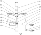
- Fig. 1 is a structural schematic diagram of an aluminum alloy hub positioning fixture.
- 1-vacuum extraction system 2-vacuum gauge, 3-electromagnetic valve, 4-compressed air system, 5-pressure gauge, 6-electromagnetic valve, 7-metal hose, 8-belt pulley, 9-metal pipe, 10-hub, 11-upper rotating shaft, 12-upper cylinder, 13-lower cylinder, 14-servo motor, 15-bearing seat, 16-belt, 17-lower rotating shaft, 18-rubber sheath, 19-trapezoidal taper sleeve A, 20-trapezoidal taper sleeve B, 21-bearing seat.
- Embodiment 1 An aluminum alloy hub positioning fixture includes a vacuum extraction system 1, a vacuum gauge 2, an electromagnetic valve 3, a compressed air system 4, a pressure gauge 5, an electromagnetic valve 6, a metal hose 7, a belt pulley 8, a metal pipe 9, an upper rotating shaft 11, an upper cylinder 12, a lower cylinder 13, a servo motor 14, a bearing seat 15, a belt 16, a lower rotating shaft 17, rubber sheaths 18, a trapezoidal taper sleeve A 19, a trapezoidal taper sleeve B 20 and a bearing seat 21.
- the vacuum system 1 includes a vacuum pump, the vacuum gauge 2 is mounted at the front end of the vacuum system 1, and the electromagnetic valve 3 is mounted at the front end of the vacuum gauge.
- the vacuum system 1 extracts vacuum
- the electromagnetic valve 3 is opened, the electromagnetic valve 6 is closed, and the vacuum gauge 2 displays the vacuum degree.
- the compressed air system 4 includes a compressed air source, the pressure gauge 5 is mounted at the front end of the compressed air system 4, and the electromagnetic valve 6 is mounted at the front end of the pressure gauge 5.
- the electromagnetic valve 6 is opened, the electromagnetic valve 3 is closed, and the pressure gauge 5 displays the pressure value of the compressed air.
- the electromagnetic valve 3 and the electromagnetic valve 6 are connected with one end of the metal hose 7.
- the other end of the metal hose 7 is connected with one end of the metal pipe 9 in the bearing seat 15, and the metal hose 7 is adopted to ensure the metal pipe 9 follows the lower rotating shaft 17 to move vertically.
- the metal pipe 9 is mounted in the inner hole of the lower rotating shaft 17, one end of the metal pipe 9 is assembled together with the inner hole of the trapezoidal taper sleeve A 19 via a bearing, and the other end of the metal pipe 9 is assembled together with the inner hole of the rotating shaft 17 via a bearing.
- One end of the lower rotating shaft 17 is mounted in the bearing seat 15, and they are assembled together via a bearing.
- the belt pulley 8 is mounted on the section, close to the bearing seat 15, of the outer surface of the lower rotating shaft 17; the other end of the lower rotating shaft 17 is mounted on the lower surface of the trapezoidal taper sleeve A 19, and they are connected together via a bolt.
- the servo motor 14 is assembled together with the belt pulley 8 via the belt 16.
- One end of the cylinder 13 is fixed on a base, the bearing seat 15 is mounted at one end of a piston rod, and the servo motor 14 is fixedly connected with the piston rod of the cylinder 13.
- One end of the cylinder 12 is fixed on the base, and the bearing seat 21 is mounted at one end of a piston rod.
- the upper rotating shaft 11 is mounted on the bearing seat 21, and they are assembled together via a bearing.
- the trapezoidal taper sleeve B 20 is mounted on the other section of the upper rotating shaft 11, and they are connected together via threads.
- the rubber sheaths 18 are mounted on the outer surfaces of both the trapezoidal taper sleeve A 19 and the trapezoidal taper sleeve B 20.
- Embodiment 2 The aluminum alloy hub positioning fixture is applied to a full automatic hub production line.
- the cylinder 12 drives the upper rotating shaft 11 to descend, till the trapezoidal taper sleeve B 20 is in contact with the cap section of the hub 10.
- a closed space is formed among the trapezoidal taper sleeve A 19, the trapezoidal taper sleeve B 20 and the hub 10.
- the electromagnetic valve 6 is closed, the electromagnetic valve 3 is opened, the vacuum system 1 extracts vacuum from the closed space via the metal pipe 9 and the metal hose 7, and when the indicated value of the vacuum gauge 2 reaches a set value, preferably a vacuum degree 3-5 Pa, it indicates that the trapezoidal taper sleeve A 19 and the trapezoidal taper sleeve B 20 have been in tight fit with the hub 10.
- a set value preferably a vacuum degree 3-5 Pa
- the servo motor 14 drives the belt pulley 8 and the lower rotating shaft 17 to rotate via the belt 16, and the lower rotating shaft 17 drives the hub 10 and the upper rotating shaft 11 to rotate together.
- the servo motor 14 stops running.
- the electromagnetic valve 6 is opened, the electromagnetic valve 3 is closed, and the vacuum system 1 stops running; the compressed air system 4 charges air into the closed space via the metal pipe 9 and the metal hose 7, and when the indicated value of the pressure gauge 5 reaches a set value, preferably 0.3-0.6 MPa, it indicates that the trapezoidal taper sleeve A 19 and the trapezoidal taper sleeve B 20 can be separated from the hub 10.
- this positioning fixture can improve the detection speed and accelerate the detection cycle; and crucially, the positioning fixture avoids the phenomenon that aluminum scraps occurs in the detection link, reduces the artificial maintenance cost, improves the production efficiency, and simultaneously reduces the phenomenon of accuracy distortion caused by accumulation of aluminum scraps.
- Embodiment 3 The aluminum alloy hub positioning fixture is applied to a hub runout tester.
- each hub is repeatedly clamped and measured 10 times, and compared with the measured data of the runout tester in the prior art, the measured results show that the extreme differences of the repeated measurement are within 0.01 mm and superior to 0.04 mm required by the prior art.
- Embodiment 4 The aluminum alloy hub positioning fixture is applied to a hub dynamic balance tester.
Landscapes
- Physics & Mathematics (AREA)
- General Physics & Mathematics (AREA)
- Engineering & Computer Science (AREA)
- Mechanical Engineering (AREA)
- Automatic Assembly (AREA)
- Testing Of Balance (AREA)
- Jigs For Machine Tools (AREA)
Description
- The present invention relates to a positioning fixture, relating to the field of machinery.
- In the prior art, an aluminum alloy hub is placed on a positioning fixture of dynamic balance and runout detection equipment by adopting a clamping mode of central hole positioning during dynamic balance and runout detection, wherein the positioning fixture adopts a steel split expansion sleeve or a steel integrated taper sleeve.
- In actual detection, the inner surface of the central hole of the aluminum alloy hub is in contact with the outer surface of the steel fixture, the central hole of the aluminum alloy hub may be damaged in the contact process of the steel fixture and the aluminum alloy hub, and a phenomenon that aluminum scraps drop occurs.
- If the positioning fixture is a steel split expansion sleeve, the dropped aluminum scraps fall into the slide way of the expansion sleeve, thus the expansion sleeve is blocked, and the positioning and clamping precision of the detection equipment and the detection results are affected directly.
- If the positioning fixture is a steel integrated taper sleeve, the dropped aluminum scraps fall onto the surface of the taper sleeve, thus aluminum is attached to the surface of the taper sleeve; meanwhile, part of the aluminum scraps may enter the inner surface of the taper sleeve, so that the clearance between the main shaft of the fixture and the taper sleeve becomes large, and the positioning and clamping precision of the detection equipment and the detection results are affected directly.
-
US 2016/368332 A1 provides a device for measuring air tightness of an aluminum alloy hub or a tyre and a method for measuring the air tightness of the aluminum alloy hub or the tyre by using the device. The device includes a pressure measurement device mounted into a hub or tyre to be measured, an inflation device in gas connection with an inside of a tyre of a wheel to be measured, and a data acquiring and processing device. The inflation device comprises a pressure gage, a gas flowmeter, a connection pipeline, a shut-off valve and a gas source, the pressure gage being in gas connection with the inside of the tyre on the aluminum alloy hub and being in gas connection with the gas flowmeter. - Upon said analysis, the application of the steel positioning fixture inevitably causes the phenomenon that aluminum scraps drop from the aluminum alloy hub, and the positioning accuracy of the fixture may be affected if the aluminum scraps are accumulated. Particularly in an automatic production line, hubs are continuously detected by the detection equipment, aluminum scraps are accumulated seriously, and if the automatic production line is stopped frequently for cleaning the aluminum scraps, the production cycle may be prolonged, the production efficiency may decline, and the short-time cleaning effect is not quite ideal.
- Thus, the present invention is aimed at providing an aluminum alloy hub positioning fixture, which does not occur dropping aluminum scraps, has small contact force in the positioning process and reduces the interference of random vibration signals to signals of detection equipment.
- The present invention provides an aluminum alloy hub positioning fixture, comprising:
- a compressed air system for charging air to a closed space, wherein a pressure gauge is mounted at the front end of the compressed air system, and an electromagnetic valve is mounted at the front end of the pressure gauge,
- a vacuum system for extracting vacuum from a closed space, wherein a vacuum gauge is mounted at the front end of the vacuum system, and an electromagnetic valve is mounted at the front end of the vacuum gauge,
- a lower rotating shaft, one end of which is connected with the trapezoidal taper sleeve A via a bolt, and the other end is connected with the bearing seat via a bearing,
wherein a lower cylinder can drive the rotating shaft to ascend, till the trapezoidal taper sleeve A connected with one end of the lower rotating shaft is in contact with the central hole of the hub, - a upper rotating shaft, wherein a bearing seat is mounted between the upper rotating shaft and the upper cylinder, and one end of the upper rotating shaft can rotate axially around the bearing seat, and a trapezoidal taper sleeve B is mounted at the other end of the upper rotating shaft via threaded connection,
wherein a cylinder can drive the upper rotating shaft to descend, till the trapezoidal taper sleeve B is in contact with the cap section of the hub, wherein a closed space is formed among the trapezoidal taper sleeve A, the trapezoidal taper sleeve B and the hub, - a metal hose, wherein the electromagnetic valve and the electromagnetic valve are connected with one end of the metal hose, and the other end of the metal hose is connected with one end of the metal pipe in the bearing seat,
wherein the vacuum system can extract vacuum from the closed space via the metal pipe and the metal hose, so that the trapezoidal taper sleeve A and the trapezoidal taper sleeve B can be in tight fit with the hub under the action of atmospheric pressure, wherein the compressed air system can charge air into the closed space via the metal pipe and the metal hose, so that the trapezoidal taper sleeve A and the trapezoidal taper sleeve B can be separated from the hub, - a servo motor, which is assembled together with the belt pulley via the belt, and drives the belt pulley and the lower rotating shaft to rotate via the belt, and the lower rotating shaft drives the hub and the upper rotating shaft to rotate together,
- The upper taper sleeve is matched with the lower taper sleeve, the upper taper sleeve acts on the cap section of a hub, and the lower taper sleeve acts on the central hole of the hub.
- In a preferred aspect of the present invention, the rubber sheaths are stuck on the surfaces of the upper taper sleeve and the lower taper sleeve.
- In a preferred aspect of the present invention, the positioning fixture can drive the hub to rotate at a high speed under the coordination of the upper rotating shaft and the lower rotating shaft.
- In a preferred aspect of the present invention, the lower rotating shaft is a hollow shaft in order to mount the metal pipe.
- In a preferred aspect of the present invention, the belt pulley is mounted on the lower rotating shaft to drive the lower rotating shaft to rotate via the belt under drive of the servo motor.
- In a preferred aspect of the present invention, when the upper taper sleeve and the lower taper sleeve are matched with the hub into a closed space, the vacuum extraction system extracts vacuum from the closed space via the metal pipe, thereby ensuring the upper taper sleeve and the lower taper sleeve are matched with the hub tightly and firmly under the action of atmospheric pressure.
- In a preferred aspect of the present invention, when the upper taper sleeve and the lower taper sleeve need to be separated from the hub after matched into the closed space, the compressed air system charges air to the closed space via the metal pipe, thereby ensuring the upper taper sleeve and the lower taper sleeve can be separated from the hub under the action of the compressed air.
- In a preferred aspect of the present invention, the vacuum system includes a vacuum pump, the vacuum gauge is mounted at the front end of the vacuum system, and the electromagnetic valve is mounted at the front end of the vacuum gauge. When the vacuum system extracts vacuum, the electromagnetic valve is opened, the electromagnetic valve is closed, and the vacuum gauge displays the vacuum degree.
- In a preferred aspect of the present invention, the compressed air system includes a compressed air source, the pressure gauge is mounted at the front end of the compressed air system, and the electromagnetic valve is mounted at the front end of the pressure gauge. When the compressed air system charges compressed air, the electromagnetic valve is opened, the electromagnetic valve is closed, and the pressure gauge displays the pressure value of the compressed air.
- In a preferred aspect of the present invention, the electromagnetic valve and the electromagnetic valve are connected with one end of the metal hose.
- In a preferred aspect of the present invention, the other end of the metal hose is connected with one end of the metal pipe in the bearing seat, and the metal hose is adopted to ensure the metal pipe follows the lower rotating shaft to move vertically.
- In a preferred aspect of the present invention, the metal pipe is mounted in the inner hole of the lower rotating shaft, one end of the metal pipe is assembled together with the inner hole of the trapezoidal taper sleeve A via a bearing, and the other end of the metal pipe is assembled together with the inner hole of the rotating shaft via a bearing.
- In a preferred aspect of the present invention, one end of the lower rotating shaft is mounted in the bearing seat, and they are assembled together via a bearing. The belt pulley is mounted on the section, close to the bearing seat, of the outer surface of the lower rotating shaft; the other end of the lower rotating shaft is mounted on the lower surface of the trapezoidal taper sleeve A, and they are connected together via a bolt.
- In a preferred aspect of the present invention, the servo motor is assembled together with the belt pulley via the belt.
- In a preferred aspect of the present invention, one end of the cylinder is fixed on a base, the bearing seat is mounted at one end of a piston rod, and the servo motor is fixedly connected with the piston rod of the cylinder.
- In a preferred aspect of the present invention, one end of the cylinder is fixed on the base, and the bearing seat is mounted at one end of a piston rod. The upper rotating shaft is mounted on the bearing seat, and they are assembled together via a bearing.
- In a preferred aspect of the present invention, the trapezoidal taper sleeve B is mounted on the other section of the upper rotating shaft, and they are connected together via threads.
- When the hub is conveyed to a position just above the cylinder via an automatic roller bed, the automatic roller bed stops running, and the cylinder drives the rotating shaft to ascend, till the trapezoidal taper sleeve A is in contact with the central hole of the hub.
- The present invention adopting the trapezoidal taper sleeves for positioning the hub is applicable to hubs having large central hole diameters, and can reduce the fixture replacing time. The rubber sheaths are mounted on the surfaces of the trapezoidal taper sleeves, thereby avoiding metal friction between the steel taper sleeves and the hub, and eliminating the phenomenon that aluminum scraps drop. The present invention adopts upper and lower rotating shafts, wherein the lower rotating shaft is a drive shaft, and the upper rotating shaft is a driven shaft. The present invention adopts a vacuum extraction mode to ensure that the positioning clamping force is sufficient to overcome centrifugal force generated by high-speed rotation of the hub. The positioning fixture is separated from the hub by charging compressed air.
- The implementation scheme of the present invention will be specified below in combination with an accompanying drawing.
-
Fig. 1 is a structural schematic diagram of an aluminum alloy hub positioning fixture. - In which, 1-vacuum extraction system, 2-vacuum gauge, 3-electromagnetic valve, 4-compressed air system, 5-pressure gauge, 6-electromagnetic valve, 7-metal hose, 8-belt pulley, 9-metal pipe, 10-hub, 11-upper rotating shaft, 12-upper cylinder, 13-lower cylinder, 14-servo motor, 15-bearing seat, 16-belt, 17-lower rotating shaft, 18-rubber sheath, 19-trapezoidal taper sleeve A, 20-trapezoidal taper sleeve B, 21-bearing seat.
- An aluminum alloy hub positioning fixture will be described in detail below in combination with
Fig. 1 . - Embodiment 1: An aluminum alloy hub positioning fixture includes a vacuum extraction system 1, a
vacuum gauge 2, an electromagnetic valve 3, a compressed air system 4, apressure gauge 5, anelectromagnetic valve 6, a metal hose 7, a belt pulley 8, a metal pipe 9, an upper rotatingshaft 11, anupper cylinder 12, alower cylinder 13, aservo motor 14, abearing seat 15, abelt 16, a lower rotatingshaft 17,rubber sheaths 18, a trapezoidaltaper sleeve A 19, a trapezoidaltaper sleeve B 20 and abearing seat 21. - The vacuum system 1 includes a vacuum pump, the
vacuum gauge 2 is mounted at the front end of the vacuum system 1, and the electromagnetic valve 3 is mounted at the front end of the vacuum gauge. When the vacuum system 1 extracts vacuum, the electromagnetic valve 3 is opened, theelectromagnetic valve 6 is closed, and thevacuum gauge 2 displays the vacuum degree. - The compressed air system 4 includes a compressed air source, the
pressure gauge 5 is mounted at the front end of the compressed air system 4, and theelectromagnetic valve 6 is mounted at the front end of thepressure gauge 5. When the compressed air system 4 charges compressed air, theelectromagnetic valve 6 is opened, the electromagnetic valve 3 is closed, and thepressure gauge 5 displays the pressure value of the compressed air. - The electromagnetic valve 3 and the
electromagnetic valve 6 are connected with one end of the metal hose 7. - The other end of the metal hose 7 is connected with one end of the metal pipe 9 in the bearing
seat 15, and the metal hose 7 is adopted to ensure the metal pipe 9 follows the lowerrotating shaft 17 to move vertically. - The metal pipe 9 is mounted in the inner hole of the lower
rotating shaft 17, one end of the metal pipe 9 is assembled together with the inner hole of the trapezoidaltaper sleeve A 19 via a bearing, and the other end of the metal pipe 9 is assembled together with the inner hole of therotating shaft 17 via a bearing. - One end of the lower
rotating shaft 17 is mounted in the bearingseat 15, and they are assembled together via a bearing. The belt pulley 8 is mounted on the section, close to the bearingseat 15, of the outer surface of the lowerrotating shaft 17; the other end of the lowerrotating shaft 17 is mounted on the lower surface of the trapezoidaltaper sleeve A 19, and they are connected together via a bolt. - The
servo motor 14 is assembled together with the belt pulley 8 via thebelt 16. - One end of the
cylinder 13 is fixed on a base, the bearingseat 15 is mounted at one end of a piston rod, and theservo motor 14 is fixedly connected with the piston rod of thecylinder 13. - One end of the
cylinder 12 is fixed on the base, and the bearingseat 21 is mounted at one end of a piston rod. The upperrotating shaft 11 is mounted on the bearingseat 21, and they are assembled together via a bearing. - The trapezoidal
taper sleeve B 20 is mounted on the other section of the upperrotating shaft 11, and they are connected together via threads. - The
rubber sheaths 18 are mounted on the outer surfaces of both the trapezoidaltaper sleeve A 19 and the trapezoidaltaper sleeve B 20. - When a
hub 10 is conveyed to a position just above thecylinder 13 via an automatic roller bed, the automatic roller bed stops running, and thecylinder 13 drives the rotatingshaft 17 to ascend, till the trapezoidaltaper sleeve A 19 is in contact with the central hole of thehub 10. - Embodiment 2: The aluminum alloy hub positioning fixture is applied to a full automatic hub production line.
- When the
hub 10 is conveyed to the position just above thecylinder 13 via the automatic roller bed, the automatic roller bed of the current detection station stops running, and thecylinder 13 drives the rotatingshaft 17 to ascend, till the trapezoidaltaper sleeve A 19 is in contact with the central hole of thehub 10. - Meanwhile, the
cylinder 12 drives the upperrotating shaft 11 to descend, till the trapezoidaltaper sleeve B 20 is in contact with the cap section of thehub 10. - A closed space is formed among the trapezoidal
taper sleeve A 19, the trapezoidaltaper sleeve B 20 and thehub 10. - At the moment, the
electromagnetic valve 6 is closed, the electromagnetic valve 3 is opened, the vacuum system 1 extracts vacuum from the closed space via the metal pipe 9 and the metal hose 7, and when the indicated value of thevacuum gauge 2 reaches a set value, preferably a vacuum degree 3-5 Pa, it indicates that the trapezoidaltaper sleeve A 19 and the trapezoidaltaper sleeve B 20 have been in tight fit with thehub 10. - After the trapezoidal
taper sleeve A 19 and the trapezoidaltaper sleeve B 20 are in tight fit with thehub 10, theservo motor 14 drives the belt pulley 8 and the lowerrotating shaft 17 to rotate via thebelt 16, and the lowerrotating shaft 17 drives thehub 10 and the upperrotating shaft 11 to rotate together. - After the
hub 10 rotates, corresponding dynamic balance or runout detection can be completed. Under the action of vacuum, the acting force between the trapezoidaltaper sleeve A 19 or the trapezoidaltaper sleeve B 20 and thehub 10 is very large and further greater than the centrifugal force generated by high-speed rotation of thehub 10. - After the detection of the
hub 10 is completed, theservo motor 14 stops running. Theelectromagnetic valve 6 is opened, the electromagnetic valve 3 is closed, and the vacuum system 1 stops running; the compressed air system 4 charges air into the closed space via the metal pipe 9 and the metal hose 7, and when the indicated value of thepressure gauge 5 reaches a set value, preferably 0.3-0.6 MPa, it indicates that the trapezoidaltaper sleeve A 19 and the trapezoidaltaper sleeve B 20 can be separated from thehub 10. - Thus, this positioning fixture can improve the detection speed and accelerate the detection cycle; and crucially, the positioning fixture avoids the phenomenon that aluminum scraps occurs in the detection link, reduces the artificial maintenance cost, improves the production efficiency, and simultaneously reduces the phenomenon of accuracy distortion caused by accumulation of aluminum scraps.
- Embodiment 3: The aluminum alloy hub positioning fixture is applied to a hub runout tester.
- 100 hubs are randomly selected, each hub is repeatedly clamped and measured 10 times, and compared with the measured data of the runout tester in the prior art, the measured results show that the extreme differences of the repeated measurement are within 0.01 mm and superior to 0.04 mm required by the prior art.
- Those skilled in the art could easily learn that the clamping force, acting on the hub, of the aluminum alloy hub positioning fixture in the present invention is further greater than the clamping force acting on the hub in the prior art. Therefore, the present invention can completely replace the prior art.
- Embodiment 4: The aluminum alloy hub positioning fixture is applied to a hub dynamic balance tester.
- 100 hubs are randomly selected, each hub is repeatedly clamped and measured 10 times, and compared with the measured data of the dynamic balance tester in the prior art, the measured dynamic balance value results show that the extreme differences of the repeated measurement are within 2 g and superior to 5 g required by the prior art.
- Those skilled in the art could easily learn that the clamping force, acting on the hub, of the aluminum alloy hub positioning fixture in the present invention is further greater than the clamping force acting on the hub in the prior art. Therefore, the present invention can completely replace the prior art.
Claims (10)
- An aluminum alloy hub positioning fixture, comprising:- a compressed air system (4) for charging air to a closed space, wherein a pressure gauge (5) is mounted at the front end of the compressed air system (4), and an electromagnetic valve (6) is mounted at the front end of the pressure gauge (5),characterized in that it further comprises:- a vacuum system (1) for extracting vacuum from a closed space, wherein a vacuum gauge (2) is mounted at the front end of the vacuum system (1), and an electromagnetic valve (3) is mounted at the front end of the vacuum gauge (2),- a lower rotating shaft (17), one end of which is connected with the trapezoidal taper sleeve A (19) via a bolt, and the other end is connected with the bearing seat (15) via a bearing,
wherein a lower cylinder (13) can drive the rotating shaft (17) to ascend, till the trapezoidal taper sleeve A (19) connected with one end of the lower rotating shaft (17) is in contact with the central hole of the hub (10),- a upper rotating shaft (11), wherein a bearing seat (21) is mounted between the upper rotating shaft (11) and the upper cylinder (12), and one end of the upper rotating shaft (11) can rotate axially around the bearing seat (21), and a trapezoidal taper sleeve B (20) is mounted at the other end of the upper rotating shaft (11) via threaded connection,
wherein a cylinder (12) can drive the upper rotating shaft (11) to descend, till the trapezoidal taper sleeve B (20) is in contact with the cap section of the hub (10), wherein a closed space is formed among the trapezoidal taper sleeve A (19), the trapezoidal taper sleeve B (20) and the hub (10),- a metal hose (7), wherein the electromagnetic valve (3) and the electromagnetic valve (6) are connected with one end of the metal hose (7), and the other end of the metal hose (7) is connected with one end of the metal pipe (9) in the bearing seat (15),
wherein the vacuum system (1) can extract vacuum from the closed space via the metal pipe (9) and the metal hose (7), so that the trapezoidal taper sleeve A (19) and the trapezoidal taper sleeve B (20) can be in tight fit with the hub (10) under the action of atmospheric pressure, wherein the compressed air system (4) can charge air into the closed space via the metal pipe (9) and the metal hose (7), so that the trapezoidal taper sleeve A (19) and the trapezoidal taper sleeve B (20) can be separated from the hub (10),- a servo motor (14), which is assembled together with the belt pulley (8) via the belt (16), and drives the belt pulley (8) and the lower rotating shaft (17) to rotate via the belt (16), and the lower rotating shaft (17) drives the hub (10) and the upper rotating shaft (11) to rotate together,wherein rubber sheaths (18) are mounted on the surfaces of both the trapezoidal taper sleeve A (19) and the trapezoidal taper sleeve B (20). - The aluminum alloy hub positioning fixture of claim 1, characterized in that the trapezoidal taper sleeve A (19) and the trapezoidal taper sleeve B (20) are in a metal step shape with each layer having a taper, and can be applied to hubs (10) having different central hole sizes.
- The aluminum alloy hub positioning fixture of claim 1, characterized in that when the vacuum extraction system (1) extracts vacuum, the vacuum degree is preferably 3-5 Pa.
- The aluminum alloy hub positioning fixture of claim 1, characterized in that when the compressed air system (4) charges air, the air charging pressure is preferably 0.3-0.6 MPa.
- The aluminum alloy hub positioning fixture of claim 1, characterized in that the lower rotating shaft (17) is a hollow shaft.
- The aluminum alloy hub positioning fixture of claim 1, characterized in that the lower rotating shaft (17) can rotate axially around the bearing seat (15).
- The aluminum alloy hub positioning fixture of claim 6, characterized in that the metal pipe (9) is assembled on the inner surface of one end, connected with the bearing seat (15), of the lower rotating shaft (17) via a bearing.
- The aluminum alloy hub positioning fixture of claim 7, characterized in that the belt pulley (8) is mounted on the outer surface of one end, connected with the bearing seat (15), of the lower rotating shaft (17) in an interference connection manner.
- The aluminum alloy hub positioning fixture of claim 1, characterized in that one end, connected with the trapezoidal taper sleeve A (19), of the metal pipe (9) is assembled on the inner surface of the trapezoidal taper sleeve A (19) via a bearing.
- The aluminum alloy hub positioning fixture of claim 8, characterized in that one end, connected with the bearing seat (15), of the metal pipe (9) is in threaded connection with the metal hose (7).
Applications Claiming Priority (1)
| Application Number | Priority Date | Filing Date | Title |
|---|---|---|---|
| CN201710635542.XA CN107283339B (en) | 2017-07-31 | 2017-07-31 | Aluminum alloy wheel hub positioning fixture |
Publications (2)
| Publication Number | Publication Date |
|---|---|
| EP3438633A1 EP3438633A1 (en) | 2019-02-06 |
| EP3438633B1 true EP3438633B1 (en) | 2020-08-26 |
Family
ID=60102990
Family Applications (1)
| Application Number | Title | Priority Date | Filing Date |
|---|---|---|---|
| EP18186337.4A Active EP3438633B1 (en) | 2017-07-31 | 2018-07-30 | Aluminum alloy hub positioning fixture |
Country Status (4)
| Country | Link |
|---|---|
| US (1) | US10495539B2 (en) |
| EP (1) | EP3438633B1 (en) |
| CN (1) | CN107283339B (en) |
| MA (1) | MA44568B1 (en) |
Families Citing this family (18)
| Publication number | Priority date | Publication date | Assignee | Title |
|---|---|---|---|---|
| CN107328377A (en) * | 2017-07-31 | 2017-11-07 | 中信戴卡股份有限公司 | A kind of wheel hop detection means |
| CN108237493B (en) * | 2018-04-04 | 2019-11-12 | 苏州优纳科技有限公司 | A kind of wheel hub detection auxiliary device |
| CN108499623B (en) * | 2018-04-13 | 2024-02-02 | 东富龙生命科技有限公司 | Automatic sample tube picking clamp with rotatable picking tube shaft |
| CN108857631A (en) * | 2018-04-30 | 2018-11-23 | 浙江中硅新材料有限公司 | A kind of fixation device for ceramic roller polishing |
| CN109798856B (en) | 2019-02-27 | 2024-02-27 | 中信戴卡股份有限公司 | First harmonic runout simulation hub |
| CN109764841B (en) * | 2019-02-27 | 2023-12-08 | 中信戴卡股份有限公司 | Simulation hub and verification method |
| CN109883372B (en) * | 2019-02-27 | 2024-04-19 | 中信戴卡股份有限公司 | Second harmonic runout simulation hub |
| CN110017749B (en) * | 2019-05-06 | 2024-03-12 | 广西玉柴机器股份有限公司 | Positioning device for measuring jumping |
| CN110361398B (en) * | 2019-07-30 | 2024-03-15 | 中信戴卡股份有限公司 | Hub chuck, hub clamp and X-ray detection device |
| CN110779657B (en) * | 2019-10-29 | 2021-07-13 | 江苏科技大学 | A kind of marine propeller static balance detection device and partial weight detection method |
| CN110802407B (en) * | 2019-12-18 | 2024-09-17 | 长沙智能制造研究总院有限公司 | Hub clamp for aircraft hub assembly line and application method thereof |
| CN111323166B (en) * | 2020-04-17 | 2022-06-03 | 新石器慧通(北京)科技有限公司 | Locking tool for detecting dynamic balance of tire and dynamic balance detection system of tire |
| CN112720303A (en) * | 2020-12-28 | 2021-04-30 | 安徽企盈汽配股份有限公司 | A positioning fixture for wheel hub production and processing |
| CN113001572B (en) * | 2021-02-26 | 2022-06-07 | 广东银谷科技股份有限公司 | Industrial robot clamping device capable of preventing object from falling off during rotation |
| CN114683189B (en) * | 2022-04-19 | 2024-07-16 | 广东梅隆科技股份有限公司 | Clamping device for belt pulley production |
| CN117268801B (en) * | 2023-11-21 | 2024-02-06 | 天津汇众轻量化科技有限公司 | Multifunctional detection equipment for automobile wheels |
| CN119223222B (en) * | 2024-11-29 | 2025-05-06 | 无锡聚量测控设备有限公司 | An automatic testing machine for automobile brake hub assembly |
| CN119880262B (en) * | 2025-01-10 | 2025-09-05 | 江苏东之宝车业股份有限公司 | Wheel hub dynamic balance detection method and system based on vibration analysis |
Family Cites Families (13)
| Publication number | Priority date | Publication date | Assignee | Title |
|---|---|---|---|---|
| AU1419597A (en) * | 1995-12-08 | 1997-06-27 | Hayes Wheels International, Inc. | Apparatus and method for leak testing vehicle wheels |
| US6330821B1 (en) * | 2000-02-14 | 2001-12-18 | The Goodyear Tire & Rubber Company | Method of detecting expansion vessel leakage |
| US6718818B2 (en) * | 2002-07-19 | 2004-04-13 | The Goodyear Tire & Rubber Company | Method of sensing air leaks in tires and tire testing machines |
| CN202878151U (en) * | 2012-07-17 | 2013-04-17 | 秦皇岛戴卡兴龙轮毂有限公司 | Centralized positioning guiding awl of wheel hub beating instrument |
| CN103144054B (en) * | 2013-02-07 | 2016-05-04 | 上海一成汽车科技有限公司 | Vehicle four-wheel position finder single-point fixture and using method thereof |
| US9248707B2 (en) * | 2013-12-25 | 2016-02-02 | Joe Huayue Zhou | Intelligent tire inflation and deflation system apparatus |
| CN103868657B (en) * | 2014-03-25 | 2016-02-03 | 中信戴卡股份有限公司 | A kind of rotating wheel air tightness detection machine |
| CN104614134B (en) * | 2015-02-03 | 2018-12-21 | 中信戴卡股份有限公司 | A method of detection aluminium alloy wheel hub air-tightness |
| EP3061963B1 (en) * | 2015-02-25 | 2018-06-13 | Continental Automotive GmbH | Valve assembly with a guide element |
| CN104972416A (en) * | 2015-06-12 | 2015-10-14 | 中信戴卡股份有限公司 | Circumferential positioning device for wheel |
| CN104865024A (en) * | 2015-06-16 | 2015-08-26 | 中信戴卡股份有限公司 | Device and method for measuring airtightness of aluminium alloy hub or tire |
| CN104907847A (en) * | 2015-06-30 | 2015-09-16 | 芜湖创智机械技术有限公司 | Automobile wheel hub clamping apparatus |
| CN105537634A (en) * | 2016-01-22 | 2016-05-04 | 中信戴卡股份有限公司 | Lathe chuck for aluminum alloy hub |
-
2017
- 2017-07-31 CN CN201710635542.XA patent/CN107283339B/en active Active
- 2017-12-12 US US15/839,171 patent/US10495539B2/en active Active
-
2018
- 2018-07-30 EP EP18186337.4A patent/EP3438633B1/en active Active
- 2018-07-30 MA MA44568A patent/MA44568B1/en unknown
Non-Patent Citations (1)
| Title |
|---|
| None * |
Also Published As
| Publication number | Publication date |
|---|---|
| US20190033159A1 (en) | 2019-01-31 |
| CN107283339A (en) | 2017-10-24 |
| US10495539B2 (en) | 2019-12-03 |
| CN107283339B (en) | 2022-12-02 |
| MA44568B1 (en) | 2020-10-28 |
| EP3438633A1 (en) | 2019-02-06 |
Similar Documents
| Publication | Publication Date | Title |
|---|---|---|
| US10495539B2 (en) | Aluminum alloy hub positioning fixture | |
| CN109855868B (en) | Dynamic test method and test equipment for axial stiffness of bearing | |
| CN204757945U (en) | Wheel Bore Measuring Machine | |
| CN111964551B (en) | Bearing roller size and circular run-out detection device and use method | |
| CN104359676A (en) | Thrust bearing experiment table | |
| CN111175159A (en) | Horizontal bat type contact fatigue testing machine | |
| CN204881526U (en) | Multi -functional detecting system of non -contact wheel | |
| CN106404398A (en) | Three-generation wheel hub bearing vibration automatic measuring instrument | |
| CN209326875U (en) | A kind of dynamic balance detecting device of axle hub brake drum assembly component | |
| CN103557811A (en) | Wheel blank positioning detection device | |
| EP3848687B1 (en) | Dynamic balancer with a frameless motor drive | |
| CN107607299B (en) | Spring pressure tests machine mandrel and positions loading device | |
| US20200240473A1 (en) | Manufacturing method for slinger used in rotary seal, and rotary seal | |
| CN205519033U (en) | Wire drawing machine rotating die box | |
| CN204346708U (en) | A motor bearing test bench | |
| CN107831006B (en) | A dynamic detection device with a pressurized rotating device | |
| CN110261106A (en) | A kind of torque detecting apparatus of hub bearing | |
| CN107655386B (en) | The detection method of clearance when locomotive traction motor bearing inner race is not disassembled | |
| CN104502104A (en) | Motor bearing test bed | |
| CN120102444A (en) | A device for detecting defects on the end face of a thin-walled bearing ring | |
| CN105904383A (en) | Fixing device of testing mechanism for bearing machining | |
| CN205049125U (en) | Wheel hub bearing inner race measuring device | |
| US12578252B2 (en) | Revolving drum arrangement for a tire test bench, tire test bench and method for testing vehicle tires | |
| CN105437141A (en) | Spiral testing rack based disassembling method of full complement cylindrical roller bearing | |
| CN206353211U (en) | A kind of bearing holder (housing, cover) steel ball detection device |
Legal Events
| Date | Code | Title | Description |
|---|---|---|---|
| PUAI | Public reference made under article 153(3) epc to a published international application that has entered the european phase |
Free format text: ORIGINAL CODE: 0009012 |
|
| STAA | Information on the status of an ep patent application or granted ep patent |
Free format text: STATUS: REQUEST FOR EXAMINATION WAS MADE |
|
| 17P | Request for examination filed |
Effective date: 20180730 |
|
| AK | Designated contracting states |
Kind code of ref document: A1 Designated state(s): AL AT BE BG CH CY CZ DE DK EE ES FI FR GB GR HR HU IE IS IT LI LT LU LV MC MK MT NL NO PL PT RO RS SE SI SK SM TR |
|
| AX | Request for extension of the european patent |
Extension state: BA ME |
|
| GRAP | Despatch of communication of intention to grant a patent |
Free format text: ORIGINAL CODE: EPIDOSNIGR1 |
|
| STAA | Information on the status of an ep patent application or granted ep patent |
Free format text: STATUS: GRANT OF PATENT IS INTENDED |
|
| INTG | Intention to grant announced |
Effective date: 20200423 |
|
| GRAS | Grant fee paid |
Free format text: ORIGINAL CODE: EPIDOSNIGR3 |
|
| GRAA | (expected) grant |
Free format text: ORIGINAL CODE: 0009210 |
|
| STAA | Information on the status of an ep patent application or granted ep patent |
Free format text: STATUS: THE PATENT HAS BEEN GRANTED |
|
| AK | Designated contracting states |
Kind code of ref document: B1 Designated state(s): AL AT BE BG CH CY CZ DE DK EE ES FI FR GB GR HR HU IE IS IT LI LT LU LV MC MK MT NL NO PL PT RO RS SE SI SK SM TR |
|
| REG | Reference to a national code |
Ref country code: GB Ref legal event code: FG4D |
|
| REG | Reference to a national code |
Ref country code: CH Ref legal event code: EP |
|
| REG | Reference to a national code |
Ref country code: AT Ref legal event code: REF Ref document number: 1306823 Country of ref document: AT Kind code of ref document: T Effective date: 20200915 |
|
| REG | Reference to a national code |
Ref country code: IE Ref legal event code: FG4D |
|
| REG | Reference to a national code |
Ref country code: DE Ref legal event code: R096 Ref document number: 602018007238 Country of ref document: DE |
|
| REG | Reference to a national code |
Ref country code: MA Ref legal event code: VAGR Ref document number: 44568 Country of ref document: MA Kind code of ref document: B1 |
|
| REG | Reference to a national code |
Ref country code: LT Ref legal event code: MG4D |
|
| PG25 | Lapsed in a contracting state [announced via postgrant information from national office to epo] |
Ref country code: GR Free format text: LAPSE BECAUSE OF FAILURE TO SUBMIT A TRANSLATION OF THE DESCRIPTION OR TO PAY THE FEE WITHIN THE PRESCRIBED TIME-LIMIT Effective date: 20201127 Ref country code: NO Free format text: LAPSE BECAUSE OF FAILURE TO SUBMIT A TRANSLATION OF THE DESCRIPTION OR TO PAY THE FEE WITHIN THE PRESCRIBED TIME-LIMIT Effective date: 20201126 Ref country code: BG Free format text: LAPSE BECAUSE OF FAILURE TO SUBMIT A TRANSLATION OF THE DESCRIPTION OR TO PAY THE FEE WITHIN THE PRESCRIBED TIME-LIMIT Effective date: 20201126 Ref country code: SE Free format text: LAPSE BECAUSE OF FAILURE TO SUBMIT A TRANSLATION OF THE DESCRIPTION OR TO PAY THE FEE WITHIN THE PRESCRIBED TIME-LIMIT Effective date: 20200826 Ref country code: LT Free format text: LAPSE BECAUSE OF FAILURE TO SUBMIT A TRANSLATION OF THE DESCRIPTION OR TO PAY THE FEE WITHIN THE PRESCRIBED TIME-LIMIT Effective date: 20200826 Ref country code: HR Free format text: LAPSE BECAUSE OF FAILURE TO SUBMIT A TRANSLATION OF THE DESCRIPTION OR TO PAY THE FEE WITHIN THE PRESCRIBED TIME-LIMIT Effective date: 20200826 Ref country code: PT Free format text: LAPSE BECAUSE OF FAILURE TO SUBMIT A TRANSLATION OF THE DESCRIPTION OR TO PAY THE FEE WITHIN THE PRESCRIBED TIME-LIMIT Effective date: 20201228 Ref country code: FI Free format text: LAPSE BECAUSE OF FAILURE TO SUBMIT A TRANSLATION OF THE DESCRIPTION OR TO PAY THE FEE WITHIN THE PRESCRIBED TIME-LIMIT Effective date: 20200826 |
|
| REG | Reference to a national code |
Ref country code: NL Ref legal event code: MP Effective date: 20200826 |
|
| REG | Reference to a national code |
Ref country code: AT Ref legal event code: MK05 Ref document number: 1306823 Country of ref document: AT Kind code of ref document: T Effective date: 20200826 |
|
| PG25 | Lapsed in a contracting state [announced via postgrant information from national office to epo] |
Ref country code: NL Free format text: LAPSE BECAUSE OF FAILURE TO SUBMIT A TRANSLATION OF THE DESCRIPTION OR TO PAY THE FEE WITHIN THE PRESCRIBED TIME-LIMIT Effective date: 20200826 Ref country code: RS Free format text: LAPSE BECAUSE OF FAILURE TO SUBMIT A TRANSLATION OF THE DESCRIPTION OR TO PAY THE FEE WITHIN THE PRESCRIBED TIME-LIMIT Effective date: 20200826 Ref country code: LV Free format text: LAPSE BECAUSE OF FAILURE TO SUBMIT A TRANSLATION OF THE DESCRIPTION OR TO PAY THE FEE WITHIN THE PRESCRIBED TIME-LIMIT Effective date: 20200826 Ref country code: PL Free format text: LAPSE BECAUSE OF FAILURE TO SUBMIT A TRANSLATION OF THE DESCRIPTION OR TO PAY THE FEE WITHIN THE PRESCRIBED TIME-LIMIT Effective date: 20200826 Ref country code: IS Free format text: LAPSE BECAUSE OF FAILURE TO SUBMIT A TRANSLATION OF THE DESCRIPTION OR TO PAY THE FEE WITHIN THE PRESCRIBED TIME-LIMIT Effective date: 20201226 |
|
| PG25 | Lapsed in a contracting state [announced via postgrant information from national office to epo] |
Ref country code: CZ Free format text: LAPSE BECAUSE OF FAILURE TO SUBMIT A TRANSLATION OF THE DESCRIPTION OR TO PAY THE FEE WITHIN THE PRESCRIBED TIME-LIMIT Effective date: 20200826 Ref country code: DK Free format text: LAPSE BECAUSE OF FAILURE TO SUBMIT A TRANSLATION OF THE DESCRIPTION OR TO PAY THE FEE WITHIN THE PRESCRIBED TIME-LIMIT Effective date: 20200826 Ref country code: RO Free format text: LAPSE BECAUSE OF FAILURE TO SUBMIT A TRANSLATION OF THE DESCRIPTION OR TO PAY THE FEE WITHIN THE PRESCRIBED TIME-LIMIT Effective date: 20200826 Ref country code: EE Free format text: LAPSE BECAUSE OF FAILURE TO SUBMIT A TRANSLATION OF THE DESCRIPTION OR TO PAY THE FEE WITHIN THE PRESCRIBED TIME-LIMIT Effective date: 20200826 Ref country code: SM Free format text: LAPSE BECAUSE OF FAILURE TO SUBMIT A TRANSLATION OF THE DESCRIPTION OR TO PAY THE FEE WITHIN THE PRESCRIBED TIME-LIMIT Effective date: 20200826 |
|
| REG | Reference to a national code |
Ref country code: DE Ref legal event code: R097 Ref document number: 602018007238 Country of ref document: DE |
|
| PG25 | Lapsed in a contracting state [announced via postgrant information from national office to epo] |
Ref country code: AL Free format text: LAPSE BECAUSE OF FAILURE TO SUBMIT A TRANSLATION OF THE DESCRIPTION OR TO PAY THE FEE WITHIN THE PRESCRIBED TIME-LIMIT Effective date: 20200826 Ref country code: AT Free format text: LAPSE BECAUSE OF FAILURE TO SUBMIT A TRANSLATION OF THE DESCRIPTION OR TO PAY THE FEE WITHIN THE PRESCRIBED TIME-LIMIT Effective date: 20200826 Ref country code: ES Free format text: LAPSE BECAUSE OF FAILURE TO SUBMIT A TRANSLATION OF THE DESCRIPTION OR TO PAY THE FEE WITHIN THE PRESCRIBED TIME-LIMIT Effective date: 20200826 |
|
| PG25 | Lapsed in a contracting state [announced via postgrant information from national office to epo] |
Ref country code: SK Free format text: LAPSE BECAUSE OF FAILURE TO SUBMIT A TRANSLATION OF THE DESCRIPTION OR TO PAY THE FEE WITHIN THE PRESCRIBED TIME-LIMIT Effective date: 20200826 |
|
| PLBE | No opposition filed within time limit |
Free format text: ORIGINAL CODE: 0009261 |
|
| STAA | Information on the status of an ep patent application or granted ep patent |
Free format text: STATUS: NO OPPOSITION FILED WITHIN TIME LIMIT |
|
| PG25 | Lapsed in a contracting state [announced via postgrant information from national office to epo] |
Ref country code: IT Free format text: LAPSE BECAUSE OF FAILURE TO SUBMIT A TRANSLATION OF THE DESCRIPTION OR TO PAY THE FEE WITHIN THE PRESCRIBED TIME-LIMIT Effective date: 20200826 |
|
| 26N | No opposition filed |
Effective date: 20210527 |
|
| PG25 | Lapsed in a contracting state [announced via postgrant information from national office to epo] |
Ref country code: SI Free format text: LAPSE BECAUSE OF FAILURE TO SUBMIT A TRANSLATION OF THE DESCRIPTION OR TO PAY THE FEE WITHIN THE PRESCRIBED TIME-LIMIT Effective date: 20200826 |
|
| REG | Reference to a national code |
Ref country code: CH Ref legal event code: PL |
|
| PG25 | Lapsed in a contracting state [announced via postgrant information from national office to epo] |
Ref country code: MC Free format text: LAPSE BECAUSE OF FAILURE TO SUBMIT A TRANSLATION OF THE DESCRIPTION OR TO PAY THE FEE WITHIN THE PRESCRIBED TIME-LIMIT Effective date: 20200826 |
|
| REG | Reference to a national code |
Ref country code: BE Ref legal event code: MM Effective date: 20210731 |
|
| PG25 | Lapsed in a contracting state [announced via postgrant information from national office to epo] |
Ref country code: LI Free format text: LAPSE BECAUSE OF NON-PAYMENT OF DUE FEES Effective date: 20210731 Ref country code: CH Free format text: LAPSE BECAUSE OF NON-PAYMENT OF DUE FEES Effective date: 20210731 |
|
| PG25 | Lapsed in a contracting state [announced via postgrant information from national office to epo] |
Ref country code: LU Free format text: LAPSE BECAUSE OF NON-PAYMENT OF DUE FEES Effective date: 20210730 |
|
| PG25 | Lapsed in a contracting state [announced via postgrant information from national office to epo] |
Ref country code: IE Free format text: LAPSE BECAUSE OF NON-PAYMENT OF DUE FEES Effective date: 20210730 Ref country code: BE Free format text: LAPSE BECAUSE OF NON-PAYMENT OF DUE FEES Effective date: 20210731 |
|
| GBPC | Gb: european patent ceased through non-payment of renewal fee |
Effective date: 20220730 |
|
| PG25 | Lapsed in a contracting state [announced via postgrant information from national office to epo] |
Ref country code: GB Free format text: LAPSE BECAUSE OF NON-PAYMENT OF DUE FEES Effective date: 20220730 |
|
| PG25 | Lapsed in a contracting state [announced via postgrant information from national office to epo] |
Ref country code: CY Free format text: LAPSE BECAUSE OF FAILURE TO SUBMIT A TRANSLATION OF THE DESCRIPTION OR TO PAY THE FEE WITHIN THE PRESCRIBED TIME-LIMIT Effective date: 20200826 |
|
| PG25 | Lapsed in a contracting state [announced via postgrant information from national office to epo] |
Ref country code: HU Free format text: LAPSE BECAUSE OF FAILURE TO SUBMIT A TRANSLATION OF THE DESCRIPTION OR TO PAY THE FEE WITHIN THE PRESCRIBED TIME-LIMIT; INVALID AB INITIO Effective date: 20180730 |
|
| PG25 | Lapsed in a contracting state [announced via postgrant information from national office to epo] |
Ref country code: MK Free format text: LAPSE BECAUSE OF FAILURE TO SUBMIT A TRANSLATION OF THE DESCRIPTION OR TO PAY THE FEE WITHIN THE PRESCRIBED TIME-LIMIT Effective date: 20200826 |
|
| PG25 | Lapsed in a contracting state [announced via postgrant information from national office to epo] |
Ref country code: MT Free format text: LAPSE BECAUSE OF FAILURE TO SUBMIT A TRANSLATION OF THE DESCRIPTION OR TO PAY THE FEE WITHIN THE PRESCRIBED TIME-LIMIT Effective date: 20200826 |
|
| PGFP | Annual fee paid to national office [announced via postgrant information from national office to epo] |
Ref country code: DE Payment date: 20250711 Year of fee payment: 8 |
|
| PGFP | Annual fee paid to national office [announced via postgrant information from national office to epo] |
Ref country code: FR Payment date: 20250730 Year of fee payment: 8 |
|
| VS25 | Lapsed in a validation state [announced via postgrant information from nat. office to epo] |
Ref country code: MA Free format text: LAPSE BECAUSE OF NON-PAYMENT OF DUE FEES Effective date: 20230731 |
|
| VSFP | Annual fee paid to validation state [announced via postgrant information from national office to epo] |
Ref country code: MA Payment date: 20220719 Year of fee payment: 5 Ref country code: MA Payment date: 20210630 Year of fee payment: 4 |
|
| PG25 | Lapsed in a contracting state [announced via postgrant information from national office to epo] |
Ref country code: TR Free format text: LAPSE BECAUSE OF FAILURE TO SUBMIT A TRANSLATION OF THE DESCRIPTION OR TO PAY THE FEE WITHIN THE PRESCRIBED TIME-LIMIT Effective date: 20200826 |