EP3438604A1 - Verfahren zum ermitteln einer lage eines zumindest abschnittsweise linienförmigen objekts und vorrichtung dazu - Google Patents
Verfahren zum ermitteln einer lage eines zumindest abschnittsweise linienförmigen objekts und vorrichtung dazu Download PDFInfo
- Publication number
- EP3438604A1 EP3438604A1 EP17184994.6A EP17184994A EP3438604A1 EP 3438604 A1 EP3438604 A1 EP 3438604A1 EP 17184994 A EP17184994 A EP 17184994A EP 3438604 A1 EP3438604 A1 EP 3438604A1
- Authority
- EP
- European Patent Office
- Prior art keywords
- line
- pixel
- detector element
- columns
- determining
- Prior art date
- Legal status (The legal status is an assumption and is not a legal conclusion. Google has not performed a legal analysis and makes no representation as to the accuracy of the status listed.)
- Granted
Links
Images


Classifications
-
- G—PHYSICS
- G01—MEASURING; TESTING
- G01B—MEASURING LENGTH, THICKNESS OR SIMILAR LINEAR DIMENSIONS; MEASURING ANGLES; MEASURING AREAS; MEASURING IRREGULARITIES OF SURFACES OR CONTOURS
- G01B11/00—Measuring arrangements characterised by the use of optical techniques
- G01B11/002—Measuring arrangements characterised by the use of optical techniques for measuring two or more coordinates
-
- G—PHYSICS
- G01—MEASURING; TESTING
- G01B—MEASURING LENGTH, THICKNESS OR SIMILAR LINEAR DIMENSIONS; MEASURING ANGLES; MEASURING AREAS; MEASURING IRREGULARITIES OF SURFACES OR CONTOURS
- G01B11/00—Measuring arrangements characterised by the use of optical techniques
- G01B11/26—Measuring arrangements characterised by the use of optical techniques for measuring angles or tapers; for testing the alignment of axes
-
- G—PHYSICS
- G06—COMPUTING OR CALCULATING; COUNTING
- G06T—IMAGE DATA PROCESSING OR GENERATION, IN GENERAL
- G06T7/00—Image analysis
- G06T7/70—Determining position or orientation of objects or cameras
-
- G—PHYSICS
- G06—COMPUTING OR CALCULATING; COUNTING
- G06V—IMAGE OR VIDEO RECOGNITION OR UNDERSTANDING
- G06V10/00—Arrangements for image or video recognition or understanding
- G06V10/40—Extraction of image or video features
- G06V10/42—Global feature extraction by analysis of the whole pattern, e.g. using frequency domain transformations or autocorrelation
- G06V10/421—Global feature extraction by analysis of the whole pattern, e.g. using frequency domain transformations or autocorrelation by analysing segments intersecting the pattern
-
- G—PHYSICS
- G06—COMPUTING OR CALCULATING; COUNTING
- G06V—IMAGE OR VIDEO RECOGNITION OR UNDERSTANDING
- G06V20/00—Scenes; Scene-specific elements
- G06V20/60—Type of objects
- G06V20/64—Three-dimensional [3D] objects
Definitions
- the invention relates to a method for determining a position of an at least partially linear object with the step of arranging the object such that a measurement object is imaged on the detector element, the detector element having detector pixels arranged in N x rows and N y columns, the lines in extend a row direction, two adjacent rows have a line spacing, the columns extend in a transverse direction, in particular perpendicular, extending to the row direction column direction, two adjacent columns have a column spacing and at least as many columns as rows exist and wherein the measurement object at an orientation angle in extends relative to the row direction on the detector element.
- the invention relates to a device for determining a position of an at least partially linear object with (a) an object receptacle for receiving the object and (b) a detector element having detector pixels arranged in N x rows and N y columns, where N x ⁇ N y , where the rows extend in one row direction, with two adjacent rows spaced one row, the columns extending in a transverse direction, in particular perpendicular, to the row direction, and two adjacent columns having a column spacing, where ( c) the object is arranged so that it is imaged on the detector element as a measurement object, wherein (d) the measurement object extends at an orientation angle relative to the line direction on the detector element and (e) with an evaluation unit which is connected to the detector element.
- the determination of the position of at least partially line-shaped objects is relevant, for example, when operating autocollimators.
- the at least partially line-shaped object is part of a light source. If the object image moves, in the present example thus the moving part of the autocollimator, then the measurement object, which could also be referred to as a measurement mark image, moves on the detector element.
- the change in position must be determined with the highest possible accuracy so that the lowest possible measurement uncertainty can be achieved.
- a second example for determining a position of an at least partially linear object is the position determination of components on a conveyor, for example a belt conveyor. Also in this case, the highest possible accuracy in determining the position of the object is desirable.
- the line-shaped object can also be a pattern, for example an interferogram, a diffraction pattern in light diffraction at a single slit, a measuring mark, a crosshair or a bar mark.
- the invention has for its object to improve the determination of the position of an at least partially linear object.
- n x ⁇ N x and n y ⁇ N y are natural, divisive numbers and where ⁇ ⁇ 10 arc minutes, preferably ⁇ ⁇ 7 arc minutes, in particular ⁇ ⁇ 3 arc minutes applies
- the method also includes the steps of determining a position, in particular a center of gravity, of the measurement object for each relevant pixel line, the pixel line being a row or a column, the resulting layers being averaged over n Px pixel lines such that N BI blocking agent layers are obtained, and wherein the position of the measurement object is in particular all, blocking agent layers is determined.
- An advantage of the method is that the position of the test object can be detected with a particularly low measurement uncertainty.
- the reason for this is that pixel effects can be largely eliminated.
- the light intensity distribution of the measurement object which could also be referred to as a measurement mark image, is incompletely measured by a CCD detector element, since it is approximated by pixels and thus falsified. From the measured light intensity distribution is closed to the position of the intensity distribution, which is thus also falsified.
- the position of subpixel extent structures can only be determined with additional knowledge within a pixel. But these are usually not available.
- the falsification by the pixel structure of the detector element leads to a systematic deviation of the specific position of a light intensity distribution from the actual position. This deviation is called pixel effect. Due to the teaching of the invention, pixel effects can theoretically be virtually completely compensated without additional knowledge.
- a further advantage is that the method according to the invention makes do without novel components and thus already existing devices can be converted with little effort.
- the object is understood to be a real object whose position is to be determined.
- the measuring object is understood to mean the image of the object on the detector element. From the position of the measurement object on the detector element is then closed to the position of the object.
- An at least partially line-shaped object is understood to mean an object which has at least one edge which is described by a route can.
- any object can be described as a route, as long as an arbitrarily large error caused by this description is accepted. But that is not meant.
- the decisive factor is that the description of the object as a line results in at most one additional measurement uncertainty, which is at most 0.8 times the total measurement uncertainty.
- the term of an initially sectionally quasi-one-dimensional object can be used. It should be noted that it is sufficient that a part of the measurement object can be described as linear. For example, an equilateral triangle in this sense is a sectionally linear object.
- pixel lines are used whose pixels lie within an evaluation range, the object being linear in the evaluation range.
- an object is used for which a deviation of the edges of the measurement object from an (ideally straight) distance in the evaluation area is at most one pixel, preferably at most half a pixel.
- determining the location is equivalent to determining a location change.
- a detector element according to claim 1 remains such a detector element, even if it is rotated by 90 °.
- a relevant pixel line is a pixel line that intersects the object to be measured.
- a difference between n x and n y is in magnitude at most 50, especially at most 10, more preferably at most two. It can be shown that in this case a particularly low measurement uncertainty is achievable.
- n x is at most N x / 10. Otherwise, the range of layers that can be detected is comparatively small. Alternatively or additionally, n y is at most N y / 10.
- n Px of the positions averaged over are at least 5, in particular at least 20.
- the measurement object moves relative to the detector element such that it is always located within a rectangular detection area, the detection area having N x, D detection area lines and N y, D detection area columns and where N x is a true divisor of N x, D and N y is a divisor of N y, D.
- the detector element or a position detection device that contains the detector element is aligned so that the object can only move in such a way that the measurement object fulfills the said requirement.
- the method comprises the steps of (i) arranging a second object such that a second measurement object extending transversely to the first measurement object is imaged on the detector element, (ii) determining a position for each relevant pixel lateral line that is transverse to the pixel lines , in particular one Center of gravity of the second measurement object, (iii) averaging the thus obtained plies over N PL , two pixel cross-lines so as to obtain second-block middle layers, and (iv) determining the position of the measurement object, in particular all, blocking means layers and, in particular, all second block means plies.
- a pixel cross line is understood to mean a line that runs transversely to a pixel line. For example, if the pixel line is a line, the pixel line is a column. If the pixel line is a column, the pixel line is one line.
- a device is preferably an autocollimator and has a light source for emitting a light beam and a reflector for reflecting the light beam, wherein the light source and the reflector are formed such that the light beam reflected by the reflector falls onto the detector element and forms the measurement object there.
- the autocollimator can be operated with a particularly low measurement uncertainty.
- n x ⁇ N x and n y ⁇ N y are natural, divisive numbers and where ⁇ ⁇ 10 arc minutes, preferably ⁇ ⁇ 7 arc minutes, in particular ⁇ ⁇ 3 arc minutes applies, and (h) the evaluation unit is set up to automatically perform a method comprising the steps of: (i) for each relevant pixel line, determining a position, in particular a centroid, of the measurement object, wherein the pixel line is a row or a column, (ii) averaging the thus obtained layers over n Px pixel lines such that blocking agent layers are obtained and (iii) determining the location of the object, in particular all, blocking means locations.
- the measuring mark extends in sections along a first line.
- the measuring mark preferably extends in sections along a second line which runs transversely, in particular perpendicular, to the first line.
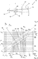
- FIG. 1 schematically shows a device according to the invention for averaging a position of an at least partially linear object in the form of an autocollimator 10 with a light source 12 for generating a measuring mark 14 which is projected onto a mirror 16.
- the autocollimator 10 also has a detector element 18 in the form of a CCD array.
- light from the light source 12 first passes through a slit diaphragm 19 with a slot in the form of the measuring mark, a beam plate 20 and then an objective 22.
- the objective 22 has a focal length f which corresponds to a distance of the detector 18 from the objective 22.
- the autocollimator 10 measures an angle ⁇ between the mirror 16 and the detector element 18 based on a displacement d of an image of the measuring mark 14 on the detector element 18.
- Plotted schematically is a measurement object 24 that is the image of the measurement mark 14. It is possible that the measuring object 24 - as in the present case - is lighter than the surroundings, for example formed by a light stripe. Conversely, however, it is also possible that the measurement object 24 is darker than the environment and, for example, as black line is formed and / or that the measurement object 24 is a single transition from light to dark or a transition that is gradually increasing and decreasing again.
- the detector element 18 has N x rows and N y columns.
- the row direction is the x direction and runs to the right.
- the column direction is the y direction and runs upwards.
- the line spacing is plotted as d y , the column spacing as d x .
- the line spacing is the distance between the centers of two pixels of the same column and adjacent lines.
- the column spacing is the distance of the centers of two pixels of the same row but of adjacent columns.
- the measuring object 24 shifts and is now identified by the reference numeral 24 '. Between these two positions is the shift d.
- the relevant pixel lines in this case are the columns S10,..., S24, since the measurement object 24 crosses these columns.
- the center of gravity M of the measurement object is determined. This results in the focal points M10, M11, ..., M24.
- a blocking means layer L which indicates the position of the mean value thus determined in units of the detector element 18.
- the first blocking means position L1 was calculated as the mean value of the centers of gravity M10 to M16.
- the second blocking means layer L2 was calculated from the positions M17 to M23.
- the detector element 18 usually has significantly more pixels than in FIG. 2 shown.
- the measuring object 24 extends over more pixels. For this reason, there are more centers of gravity M K and thus more blocking means layers L.
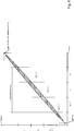
- FIG. 3a shows the dependence of the measured intensity I in any, for example, standardized, units.
- FIG. 3b shows the calculated position deviation in pixels over the actual position in pixels. Shown is an analytical function based on the calculated positions Fig. 3a was chosen arbitrarily to illustrate the operation of the method. The function simulates the difference between the calculated and the actual position of the DUT for each individual column. Due to the pixel grid of the detector, this relationship is always periodic with 1 pixel.
- Figure 3c shows the measured positions as a function of the actual position when the method according to the invention is used.
- FIG. 4a shows a second embodiment of a device according to the invention for determining a position of an object 26, which may be, for example, an optical component or a wafer. This object 26 is arranged on an object receptacle 28 in the form of a conveying direction. A camera 30, which includes the detector element 18, looks at the object 26.
- FIG. 4b shows the arrangement according to FIG. 4a in a view from above.
- the location of the object 26 is determined as described above.
- the device comprises an evaluation unit 32, which is connected to the detector element 18 and automatically executes the method described above, so that a position with respect to a predetermined coordinate system of the object 26 is calculated.
- the object 26 may have a schematically drawn measuring mark 14, but this is not necessary as long as the object 26 itself is at least partially line-shaped.
- FIG. 5 shows a schematic view of an image on the detector element 18, wherein a second measurement object 25 is present, which extends transversely, in the present case, perpendicular to the first measuring object 24.
- the first measurement object 24 and the second measurement object 25 together form a measurement mark image.
- FIG. 6 shows the measurement object 24 that extends within an illumination area.
- the illumination area encloses the entire measurement object 24.
- the values of its dimensions Nx, BB , Ny, BB are irrelevant and may be greater than the detector.
- the minimum corners of the lighting area are indicated. If the measuring object 24 changes its position, the position of the illumination area may change.
- the illumination range is an upper limit for the choice of parameters, since the averaging can only be performed via pixel lines containing the measurement object.
- the evaluation area B A results from the totality of the selected blocks.
Landscapes
- Engineering & Computer Science (AREA)
- Physics & Mathematics (AREA)
- General Physics & Mathematics (AREA)
- Theoretical Computer Science (AREA)
- Multimedia (AREA)
- Computer Vision & Pattern Recognition (AREA)
- Length Measuring Devices By Optical Means (AREA)
Abstract

Description
- Die Erfindung betrifft ein Verfahren zum Ermitteln einer Lage eines zumindest abschnittsweise linienförmigen Objekts mit dem Schritt eines Anordnens des Objekts, sodass auf dem Detektorelement ein Messobjekt abgebildet wird, wobei das Detektorelement in Nx Zeilen und Ny Spalten angeordnete Detektorpixel aufweist, sich die Zeilen in eine Zeilenrichtung erstrecken, zwei benachbarte Zeilen einen Zeilenabstand haben, sich die Spalten in eine quer, insbesondere senkrecht, zur Zeilenrichtung verlaufende Spaltenrichtung erstrecken, zwei benachbarte Spalten einen Spaltenabstand haben und zumindest so viele Spalten wie Zeilen existieren und wobei sich das Messobjekt unter einem Orientierungswinkel in relativ zur Zeilenrichtung auf dem Detektorelement erstreckt.
- Gemäß einem zweiten Aspekt betrifft die Erfindung eine Vorrichtung zum Ermitteln einer Lage eines zumindest abschnittsweise linienförmigen Objekts mit (a) einer Objektaufnahme zum Aufnehmen des Objekts und (b) einem Detektorelement, das in Nx Zeilen und Ny Spalten angeordnete Detektorpixel aufweist, wobei Nx ≥ Ny gilt, wobei sich die Zeilen in eine Zeilenrichtung erstrecken, wobei zwei benachbarte Zeilen einen Zeilenabstand haben, wobei sich die Spalten in eine quer, insbesondere senkrecht, zur Zeilenrichtung verlaufende Spaltenrichtung erstrecken und wobei zwei benachbarte Spalten einen Spaltenabstand haben, wobei (c) das Objekt so angeordnet ist, dass es auf dem Detektorelement als Messobjekt abgebildet wird, wobei (d) sich das Messobjekt unter einem Orientierungswinkel relativ zur Zeilenrichtung auf dem Detektorelement erstreckt und (e) mit einer Auswerteeinheit, die mit dem Detektorelement verbunden ist.
- Die Ermittlung der Lage zumindest abschnittsweise linienförmiger Objekte ist beispielsweise beim Betreiben von Autokollimatoren relevant. In diesem Fall ist das zumindest abschnittsweise linienförmige Objekt ein Teil einer Lichtquelle. Bewegt sich die Objektaufnahme, im vorliegenden Beispiel also der bewegliche Teil des Autokollimators, so bewegt sich das Messobjekt, das auch als Messmarkenbild bezeichnet werden könnte, auf dem Detektorelement. Die Positionsveränderung muss mit möglichst hoher Genauigkeit bestimmt werden, damit eine möglichst geringe Messunsicherheit erzielt werden kann. Ein zweites Beispiel für die Ermittlung einer Lage eines zumindest abschnittsweise linienförmigen Objekts ist die Positionsermittlung von Bauteilen auf einem Förderer, beispielsweise einem Bandförderer. Auch in diesem Fall ist eine möglichst hohe Genauigkeit bei der Bestimmung der Lage des Objekts wünschenswert.
- Das linienförmige Objekt kann auch ein Muster sein, beispielsweise ein Interferogramm, ein Beugungsbild bei einer Lichtbeugung an einem Einzelspalt, eine Messmarke, ein Fadenkreuz oder eine Strichmarke.
- Der Erfindung liegt die Aufgabe zugrunde, das Ermitteln der Lage eines zumindest abschnittsweise linienförmigen Objekts zu verbessern.
- Die Erfindung löst das Problem durch ein gattungsgemäßes Verfahren, bei dem für den Orientierungswinkel α die Formel

- Gemäß einem zweiten Aspekt löst die Erfindung das Problem durch eine gattungsgemäße Vorrichtung, bei der für den Orientierungswinkel die Formel

- Vorteilhaft an dem Verfahren ist, dass die Lage des Messobjekts mit besonders geringer Messunsicherheit erfasst werden kann. Der Grund dafür ist, dass Pixeleffekte zum großen Teil eliminiert werden können. Die Licht-Intensitätsverteilung des Messobjekts, das auch als Messmarkenbild bezeichnet werden könnte, wird von einem CCD-Detektorelement unvollständig gemessen, da sie durch Pixel approximiert und damit verfälscht wird. Aus der gemessenen Licht-Intensitätsverteilung wird auf die Position der Intensitätsverteilung geschlossen, die damit ebenfalls verfälscht ist. Die Position von Strukturen mit Subpixel-Ausdehnung kann beispielsweise nur mit zusätzlichen Kenntnissen innerhalb eines Pixels bestimmt werden. Die aber liegen in der Regel nicht vor. Die Verfälschung durch die Pixelstruktur des Detektorelements führt zu einer systematischen Abweichung der bestimmten Position einer Lichtintensitätsverteilung gegenüber der tatsächlichen Position. Diese Abweichung wird Pixeleffekt genannt. Durch die erfindungsgemäße Lehre können Pixeleffekte ohne zusätzliche Kenntnisse theoretisch quasi vollständig ausgeglichen werden.
- Vorteilhaft ist zudem, dass das erfindungsgemäße Verfahren ohne neuartige Bauteile auskommt und so mit geringem Arbeitsaufwand bereits bestehende Vorrichtungen umgerüstet werden können.
- Im Rahmen der folgenden Beschreibung wird unter dem Objekt ein realer Gegenstand verstanden wird, dessen Position ermittelt werden soll. Unter dem Messobjekt hingegen wird das Bild des Objekts auf dem Detektorelement verstanden. Aus der Lage des Messobjekts auf dem Detektorelement wird dann auf die Lage des Objekts geschlossen.
- Unter einem zumindest abschnittsweise linienförmigen Objekt wird ein Objekt verstanden, das zumindest eine Kante hat, die durch eine Strecke beschrieben werden kann. Selbstverständlich kann prinzipiell jedes Objekt als Strecke beschrieben werden, solange ein beliebig großer Fehler, der durch diese Beschreibung verursacht wird, akzeptiert wird. Das aber ist nicht gemeint. Maßgeblich ist, dass durch die Beschreibung des Objekts als Linie höchstens eine zusätzliche Messunsicherheit bedingt wird, die höchstens das 0,8-fache der gesamten Messunsicherheit ausmacht. Insbesondere kann statt des Begriffs eines zumindest abschnittsweise linienförmigen Objekts der Begriff eines zunächst abschnittsweise quasieindimensionalen Objekts verwendet werden. Es sei darauf hingewiesen, dass es ausreichend ist, dass ein Teil des Messobjekts als linienförmig beschrieben werden kann. Beispielsweise ist auch ein gleichseitiges Dreieck in diesem Sinn ein abschnittsweise linienförmiges Objekt.
- Vorzugsweise werden nur solche Pixellinien verwendet, deren Pixel innerhalb eines Auswertebereichs liegen, wobei das Objekt im Auswertebereich linienförmig ist. Insbesondere wird ein solches Objekt verwendet, für das eine Abweichung der Kanten des Messobjekts von einer (ideal geraden) Strecke im Auswertebereich höchstens einen Pixel, vorzugsweise höchstens ein halbes Pixel beträgt.
- Unter dem Merkmal, dass eine Lage des Objekts beschrieben wird, wird insbesondere verstanden, dass die Lage relativ zu einer Ausgangs-Lage bestimmt wird. In anderen Worten ist das Bestimmen der Lage äquivalent zu dem Bestimmen einer Lageänderung.
- Dass mehr Zeilen als Spalten existieren, soll lediglich die Benennung von Spalten und Zeilen vereinfachen. In anderen Worten bleibt ein Detektorelement gemäß Anspruch 1 ein solches Detektorelement, auch wenn es um 90° gedreht wird.
- Unter einer relevanten Pixellinie wird eine Pixellinie verstanden, die das Messobjekt schneidet.
- Günstig ist es, wenn die Detektorpixel quadratisch sind, das ist aber nicht notwendig. Wenn sie quadratisch sind, entspricht der Abstand dy zweier Zeilen vorzugsweise dem Abstand dx zweier Spalten. Insbesondere gilt dx = dy ± 5 %.
- Gemäß einer bevorzugten Ausführungsform beträgt eine Differenz zwischen nx und ny betragsmäßig höchstens 50, insbesondere höchstens 10, besonders bevorzugt höchstens zwei. Es lässt sich zeigen, dass in diesem Fall eine besonders geringe Messunsicherheit erreichbar ist.
- Günstig ist es, wenn nx höchstens Nx/10 beträgt. Anderenfalls ist der Bereich der Lagen, die erfasst werden können, vergleichsweise klein. Alternativ oder zusätzlich beträgt ny höchstens Ny/10.
- Günstig ist es, wenn die Zahlen nPx der Positionen, über die gemittelt wird, zumindest 5, insbesondere zumindest 20, beträgt. Je größer die Zahl der Pixellinien nPx ist, über die gemittelt wird, desto genauer kann die Lage ermittelt werden. Für praktische Anwendungen wird in der Regel ein Kompromiss zwischen einer möglichst geringen Messunsicherheit einerseits und einem großen Bereich an vermessbaren Positionen andererseits angestrebt.
- Gemäß einer bevorzugten Ausführungsform bewegt sich das Messobjekt so relativ zum Detektorelement, dass es sich stets innerhalb eines rechteckigen Detektionsbereichs befindet, wobei der Detektionsbereich Nx,D Detektionsbereichs-Zeilen und Ny,D Detektionsbereichs-Spalten hat und wobei Nx ein echter Teiler von Nx,D ist und Ny ein Teiler von Ny,D ist. In anderen Worten wird das Detektorelement oder eine Lage-Erfassungsvorrichtung, die das Detektorelement enthält, so ausgerichtet, dass das Objekt sich nur auf eine Art und Weise bewegen kann, dass das Messobjekt die genannte Anforderung erfüllt.
- Günstig ist es, wenn die Pixellinie eine Spalte und nPx = nx ist, wenn nx > ny gilt und dass die Pixellinie eine Zeile und nPx = ny ist, wenn nx < ny gilt. So wird erreicht, dass stets über eine möglichst große Anzahl an Pixellinien gemittelt wird, was zu einer geringen Messunsicherheit führt.
- Vorzugsweise umfasst das Verfahren die Schritte (i) Anordnen eines zweiten Objekts, sodass auf dem Detektorelement ein zweites Messobjekt abgebildet wird, das sich quer zum ersten Messobjekt erstreckt, (ii) für jede relevante Pixelquerlinie, die quer zu den Pixellinien verläuft, Bestimmen einer Position, insbesondere eines Schwerpunkts, des zweiten Messobjekts, (iii) Mitteln der so erhaltenen Lagen über NPL, zwei Pixelquerlinien, sodass Zweitblockmittel-Lagen erhalten werden und (iv) Bestimmen der Lage des Messobjekts aus, insbesondere allen, Blockmittel-Lagen und, insbesondere allen, Zweitblockmittel-Lagen. Es ist prinzipiell nicht möglich, eine Verschiebung des Messobjekts und damit des Objekts in eine Richtung entlang dessen linienförmiger Erstreckung zu bestimmen. In Richtung quer, insbesondere senkrecht, dazu hingegen ergibt sich bei einer solchen Verschiebung die geringstmögliche Messunsicherheit. Durch das Anordnen von zwei Objekten, sodass zwei zueinander quer verlaufende Messobjekte entstehen, wird damit erreicht, dass jegliche Verschiebung der beiden Objekte mit höchstmöglicher Genauigkeit erfasst werden kann. Günstig ist es, wenn die beiden Objekte an ein und demselben Gegenstand ausgebildet sind. Beispielsweise bilden die beiden Objekte ein Fadenkreuz auf einem Gegenstand, dessen Lage zu vermessen ist.
- Unter einer Pixelquerlinie wird eine Linie verstanden, die quer zu einer Pixellinie verläuft. Ist beispielsweise die Pixellinie eine Zeile, so ist die Pixelquerlinie eine Spalte. Ist hingegen die Pixellinie eine Spalte, so ist die Pixelquerlinie eine Zeile.
- Eine erfindungsgemäße Vorrichtung ist vorzugsweise ein Autokollimator und weist eine Lichtquelle zum Aussenden eines Lichtstrahls und einen Reflektor zum Reflektieren des Lichtstrahls auf, wobei die Lichtquelle und der Reflektor so ausgebildet sind, dass der vom Reflektor reflektierte Lichtstrahl auf das Detektorelement fällt und dort das Messobjekt bildet. Auf diese Weise kann der Autokollimator mit einer besonders geringen Messunsicherheit betrieben werden.
- Erfindungsgemäß ist insbesondere auch ein Autokollimator mit (a) einer Lichtquelle zum Erzeugen einer Messmarke, (b) einem Spiegel und (c) einem Detektorelement, das in Nx Zeilen und Ny Spalten angeordnete Detektorpixel aufweist, wobei Nx ≥ Ny gilt, wobei sich die Zeilen in eine Zeilenrichtung erstrecken, wobei zwei benachbarte Zeilen einen Zeilenabstand haben, wobei sich die Spalten in eine quer, insbesondere senkrecht, zur Zeilenrichtung verlaufende Spaltenrichtung erstrecken und wobei zwei benachbarte Spalten einen Spaltenabstand haben, (d) wobei die Lichtquelle und der Spiegel so angeordnet sind, dass die Messmarke auf dem Detektorelement als Messobjekt abgebildet wird, (e) wobei sich das Messobjekt unter einem Orientierungswinkel relativ zur Zeilenrichtung auf dem Detektorelement erstreckt, (f) einer Auswerteeinheit, die mit dem Detektorelement verbunden ist, wobei (g) für den Orientierungswinkel die Formel

- Die Messmarke erstreckt sich abschnittsweise entlang einer ersten Linie. Vorzugsweise erstreckt sich die Messmarke zudem abschnittsweise entlang einer zweiten Linie, die quer, insbesondre senkrecht, zu ersten Linie verläuft.
- Im Folgenden wird die Erfindung anhand der beigefügten Zeichnungen näher erläutert. Dabei zeigt
- Figur 1
- eine erfindungsgemäße Vorrichtung in Form eines Autokollimators zum Durchführung eines erfindungsgemäßen Verfahrens,
- Figur 2
- eine schematische Ansicht des Messobjekts auf dem Detektorelement,
- Figur 3a
- eine theoretische Berechnung der von verschiedenen Pixeln einer Zeile gemessenen Intensitäten,
- Figur 3b
- die Abweichung der gemessenen Position von der tatsächlichen Position bei einer Auswertung nach dem Stand der Technik,
- Figur 3c
- ein Diagramm, bei dem die gemessene Position über der tatsächlichen Position aufgetragen ist, wenn ein erfindungsgemäßes Verfahren zur Auswertung verwendet wird,
- Figur 3d
- eine Darstellung der Positionsabweichung über der tatsächlichen Position.
- Figur 4a
- zeigt eine schematische Ansicht einer erfindungsgemäßen Vorrichtung zum Ermitteln der Lage eines Objekts,
- Figur 4b
- zeigt eine Ansicht von oben auf die Vorrichtung gemäß
Figur 4a , und - Figur 5
- zeigt eine schematische Ansicht eines ersten und eines zweiten Messobjekts auf dem Detektorelement.
- Figur 6
- zeigt eine weitere schematische Ansicht zur Erläuterung des erfindungsgemäßen Verfahrens.
-
Figur 1 zeigt schematisch eine erfindungsgemäße Vorrichtung zum Mitteln einer Lage eines zumindest abschnittsweise linienförmigen Objekts in Form eines Autokollimators 10 mit einer Lichtquelle 12 zum Erzeugen einer Messmarke 14, die auf einen Spiegel 16 projiziert wird. Der Autokollimator 10 besitzt zudem ein Detektorelement 18 in Form eines CCD-Arrays. Licht von der Lichtquelle 12 durchläuft im vorliegenden Fall zunächst eine Schlitzblende 19 mit einem Schlitz in Form der Messmarke, einen Strahlteller 20 und danach ein Objektiv 22. Das Objektiv 22 hat eine Brennweite f, die einem Abstand des Detektors 18 vom Objektiv 22 entspricht. Der Autokollimator 10 misst einen Winkel β zwischen dem Spiegel 16 und dem Detektorelement 18 anhand einer Verschiebung d eines Bildes der Messmarke 14 auf dem Detektorelement 18. -
Figur 2 zeigt schematisch das Detektorelement 18, das aus einer Vielzahl an Pixeln Pi,j (i = 1, 2, ..., Nx und j = 1, 2, ..., Ny) aufgebaut ist. Schematisch eingezeichnet ist ein Messobjekt 24, dass das Abbild der Messmarke 14 ist. Es ist möglich, dass das Messobjekt 24 - wie im vorliegenden Fall - heller ist als die Umgebung, beispielsweise durch einen hellen Streifen gebildet ist. Umgekehrt ist es aber auch möglich, dass das Messobjekt 24 dunkler ist als die Umgebung und beispielsweise als schwarzer Strich gebildet ist und/oder dass das Messobjekt 24 ein einzelner Übergang von hell nach dunkel ist oder ein Übergang, der graduell ansteigend und wieder abnehmend ist. - Das Detektorelement 18 besitzt Nx Zeilen und Ny Spalten. Die Zeilenrichtung ist die x-Richtung und verläuft nach rechts. Die Spaltenrichtung ist die y-Richtung und verläuft nach oben. Der Zeilenabstand ist als dy eingezeichnet, der Spaltenabstand als dx. Der Zeilenabstand ist der Abstand der Mittelpunkte von zwei Pixeln gleicher Spalte und benachbarter Zeilen. Der Spaltenabstand ist der Abstand der Mittelpunkte von zwei Pixeln gleicher Zeile aber benachbarter Spalten.
- Es ist zu erkennen, dass das Messobjekt 24 unter einem Orientierungswinkel α zum Detektorelement orientiert ist, für den im vorliegenden Fall

- Ändert sich der Winkel β, so verschiebt sich das Messobjekt 24 und wird nun mit dem Bezugszeichen 24', gekennzeichnet. Zwischen diesen beiden Positionen befindet sich die Verschiebung d.
- Da nx = 7 > 6 = ny gilt, werden als Pixellinien Spalten und nPx = 7 gewählt. Die relevanten Pixellinien sind in diesem Fall die Spalten S10, ..., S24, da das Messobjekt 24 diese Spalten kreuzt. Für jede der relevanten Pixellinien S10, ..., S24 wird der Schwerpunkt M des Messobjekts bestimmt. Es ergeben sich so die Schwerpunkte M10, M11, ..., M24.
- In einem nachfolgendem Schritt werden die so erhaltenen Positionen MK (k = 1, ..., 23) über nPx Pixellinien, im vorliegenden Fall nPx = nx = 7 Pixellinien, gemittelt, nämlich die Spalten S10 bis S16. Es wird daraus eine Blockmittel-Lage L ermittelt, die die Position des so ermittelten Mittelwerts in Einheiten des Detektorelements 18 angibt. Aus den nächsten nPx = 7 Pixellinien S17 bis S23 wird eine zweite Blockmittel-Lage und L2 berechnet. Um die Darstellung zu vereinfachen werden lediglich die Blockmittel-Lagen L1 und L2 eingezeichnet. Die erste Blockmittel-Lage L1 wurde berechnet als Mittelwert der Schwerpunkte M10 bis M16. Die zweite Blockmittel-Lage L2 wurde berechnet aus den Positionen M17 bis M23.
- Es sei darauf hingewiesen, dass das Detektorelement 18 in aller Regel deutlich mehr Pixel aufweist als in
Figur 2 gezeigt. Zudem erstreckt sich das Messobjekt 24 über mehr Pixel. Aus diesem Grund existieren mehr Schwerpunkte MK und damit mehr Blockmittel-Lagen L. - Aus der Gesamtheit der Blockmittel-Lagen LK (hier: K = 1, 2) wird eine Gerade G1 berechnet. Verändert sich der Winkel β (vgl.
Figur 1 ), so verschiebt sich die Gerade G1 um die Verschiebung d, sodass sich die Gerade G2 ergibt. Aus der so bestimmten Verschiebung d wird der Winkel β berechnet. -
Figur 3a zeigt die Abhängigkeit der gemessenen Intensität I in beliebigen, beispielsweise normierten, Einheiten. -
Figur 3b zeigt die daraus berechnete Positionsabweichung in Pixeln über der tatsächlichen Position in Pixeln. Gezeigt ist eine analytische Funktion, die in Anlehnung an die berechneten Positionen ausFig. 3a willkürlich gewählt wurde, um die Funktionsweise des Verfahrens bildlich darzustellen. Die Funktion simuliert die Differenz zwischen berechneter und tatsächlicher Position des Messobjekts für jede einzelne Spalte. Aufgrund des Pixelrasters des Detektors ist dieser Zusammenhang immer periodisch mit 1 Pixel. -
Figur 3c zeigt die gemessenen Positionen in Abhängigkeit von der tatsächlichen Position, wenn das erfindungsgemäße Verfahren angewendet wird. -
Figur 3d zeigt die Positionsabweichung. Es ist zu erkennen, dass diese inFigur 3b gezeigte Positionsabweichung um den Faktor 10-3 kleiner ist. Positionsabweichungen sind die Abweichungen der berechneten Blockmittel-Lagen von den tatsächlichen Positionen. Hier sind simulierte Ergebnisse gezeigt, die die Funktionsweise des Verfahrens demonstrieren. Der Faktor 10-3 ist ein reines Simulationsergebnis und kann in realen Bedingungen anders sein. Die Periodizität der Abweichung der Blockmittel-Lagen eignet sich gut für eine quantitative Aussage. Die Periode TBI hängt mit der Anzahl der gemittelten Pixellinien zusammen, im Beispiel ist dies TBI = 1/nx = 1/7 Px.Figur 4a zeigt eine zweite Ausführungsform einer erfindungsgemäßen Vorrichtung zum Ermitteln einer Lage eines Objekts 26, bei dem es sich beispielsweise um ein optisches Bauteil oder einen Wafer handeln kann. Dieses Objekt 26 ist auf einer Objektaufnahme 28 in Form einer Förderrichtung angeordnet. Eine Kamera 30, die das Detektorelement 18 umfasst, blickt auf das Objekt 26. -
Figur 4b zeigt die Anordnung gemäßFigur 4a in einer Ansicht von oben. Die Lage des Objekts 26 wird wie oben beschrieben ermittelt. Dazu umfasst die Vorrichtung eine Auswerteeinheit 32, die mit dem Detektorelement 18 verbunden ist und automatisch das oben beschriebene Verfahren ausführt, sodass eine Position bezüglich eines vorgegebenen Koordinatensystems des Objekts 26 berechnet wird. - Das Objekt 26 kann eine schematisch eingezeichnete Messmarke 14 aufweisen, das ist aber nicht notwendig, solange das Objekt 26 selbst zumindest abschnittsweise linienförmig ist.
-
Figur 5 zeigt eine schematische Ansicht eines Bildes auf dem Detektorelement 18, wobei ein zweites Messobjekt 25 vorhanden ist, das sich quer, im vorliegenden Fall senkrecht, zum ersten Messeobjekt 24 erstreckt. Das erste Messobjekt 24 und das zweite Messobjekt 25 bilden gemeinsam ein Messmarkenbild. -
Figur 6 zeigt das Messobjekt 24, das sich innerhalb eines Beleuchtungsbereichs erstreckt. Der Beleuchtungsbereich umschließt das gesamte Messobjekt 24. Die Werte seiner Ausdehnungen Nx,BB, NY,BB sind nicht relevant und er kann größer sein als der Detektor. InFigur 6 sind die minimalen Ecken des Beleuchtungsbereiches gekennzeichnet. Verändert das Messobjekt 24 seine Lage, kann sich die Lage des Beleuchtungsbereichs verändern. Der Beleuchtungsbereich ist eine obere Grenze für die Wahl der Parameter, denn die Mittelung kann nur über Pixellinien durchgeführt werden, die das Messobjekt enthalten. - Der Auswertebereich BA ergibt sich aus der Gesamtheit der ausgewählten Blöcke. Ein einzelner Block besteht aus nx Spalten oder ny Zeilen. Im Beispiel sind dies genau nx = 7 Spalten. In
Figur 6 sind drei mögliche Blöcke gekennzeichnet. Der Auswertebereich erstreckt sich dann über NBI · nx = 3 · 7 = 21 Spalten. In y-Richtung muss jeder Block vollständig innerhalb des Beleuchtungsbereichs und des Detektorelements liegen. Ändert das Messobjekt 24 seine Lage, ändert sich auch die Lage des Auswertebereichs, um die genannten Bedingungen immer zu erfüllen. Außerdem können adaptiv beliebige Blöcke von der Auswertung ausgeschlossen werden.Bezugszeichenliste 10 Autokollimator M Schwerpunkt 12 Lichtquelle NBI Anzahl der Blöcke, über die gemittelt wird 14 Messmarke 16 Spiegel nPx Zahl der Pixellinien pro Block, über die gemittelt wird 18 Detektorelement 19 Schlitzblende Nx Zeilenanzahl Ny Spaltenanzahl 20 Strahlteiler 22 Objektiv Pi,j Pixel 24 Messobjekt S Spalte 25 zweites Messobjekt Z Zeile 26 Objekt RS Spaltenrichtung 28 Objektaufnahme RZ Zeilenrichtung 30 Kamera 32 Auswerteeinheit α Orientierungswinkel β Winkel BB Beleuchtungsbereich d Verschiebung D Detektionsbereich f Brennweite G Gerade i Laufindex j Laufindex k Laufindex L Blockmittel-Lage
Claims (9)
- Verfahren zum Ermitteln einer Lage eines zumindest abschnittsweise linienförmigen Objekts (26), mit dem Schritt(i) Anordnen des Objekts (26), sodass auf dem Detektorelement (18) ein Messobjekt (24) abgebildet wird,(ii) wobei das Detektorelement (18)- in Nx Zeilen (Z) und Ny Spalten (S) angeordnete Detektorpixel (Pi) aufweist,- sich die Zeilen (Z) in eine Zeilenrichtung (Rz) erstrecken,- zwei benachbarte Zeilen (Z) einen Zeilenabstand (dy) haben,- sich die Spalten (S) in eine quer, insbesondere senkrecht, zur Zeilenrichtung (Rz) verlaufende Spaltenrichtung (Rs) erstrecken,- zwei benachbarte Spalten (S) einen Spaltenabstand (dx) haben und- zumindest so viele Spalten (S) wie Zeilen (Z) existieren, und(iii) wobei sich das Messobjekt (24) unter einem Orientierungswinkel (α) relativ zur Zeilenrichtung (Rz) auf dem Detektorelement (18) erstreckt,
dadurch gekennzeichnet, dass(iv) für den Orientierungswinkel (α) die Formel
wobei nx < Nx und ny < Ny natürliche, teilerfremde Zahlen sind und
wobei ε < 10 Bogenminute gilt und dass das Verfahren die folgenden Schritte umfasst:(v) für jede relevante Pixellinie (S, Z) Bestimmen einer Position (M), insbesondere eines Schwerpunkts (M), des Messobjekts (24), wobei die Pixellinie eine Zeile oder eine Spalte ist,(vi) Mitteln der so erhaltenen Positionen (M) über nPx Pixellinien, sodass Blockmittel-Lagen (L) erhalten werden und(vii) Bestimmen der Lage des Messobjekts (24) aus, insbesondere allen, Blockmittel-Lagen (L). - Verfahren nach Anspruch 1, dadurch gekennzeichnet, dass- eine Differenz zwischen nx und ny betragsmäßig höchstens 50 beträgt, insbesondere höchstens 10 und/oder- nx höchstens Nx/10 beträgt und/oder ny höchstens Ny/10 beträgt.
- Verfahren nach einem der vorstehenden Ansprüche, dadurch gekennzeichnet, dass NPI zumindest 5, insbesondere zumindest 20, beträgt.
- Verfahren nach einem der vorstehenden Ansprüche, dadurch gekennzeichnet, dass- sich das Messobjekt (24) relativ zum Detektorelement (18) bewegt und stets innerhalb eines rechteckigen Detektionsbereichs (D) liegt,- wobei der Detektionsbereich Nx,D Detektionsbereichs-Zeilen und Ny,D Detektionsbereich-Spalten hat und- wobei nx ein echter Teiler von Nx,D und ny ein Teiler von Ny,D ist.
- Verfahren nach einem der vorstehenden Ansprüche, dadurch gekennzeichnet, dass- die Pixellinien Spalten sind und nPx = nx ist, wenn nx > ny gilt und- die Pixellinien Zeilen sind und nPx = ny ist, wenn nx < ny gilt.
- Verfahren nach einem der vorstehenden Ansprüche, gekennzeichnet durch die Schritte:(i) Anordnen eines zweiten Objekts (26), sodass auf dem Detektorelement (18) ein zweites Messobjekt (25) abgebildet wird, das sich quer zum ersten Messobjekt (24.1) erstreckt,(ii) für jede relevante Pixelquerlinie, die quer zu den Pixellinien verläuft, Bestimmen einer Position (M), insbesondere eines Schwerpunkts (M), des zweiten Messobjekts (24.2),(iii) Mitteln der so erhaltenen Lagen über nPx,2 Pixelquerlinien, sodass Zweitblockmittel-Lagen erhalten werden und(iv) Bestimmen der Lage des Messobjekts (24) aus, insbesondere allen, Blockmittel-Lagen (L) und, insbesondere allen, Zweitblockmittel-Lagen.
- Vorrichtung zum Ermitteln einer Lage eines zumindest abschnittsweise linienförmigen Objekts (26), mit(a) einer Objektaufnahme (28) zum Aufnehmen des Objekts (26) und(b) einem Detektorelement (18), das- in Nx Zeilen (Z) und Ny Spalten (S) angeordnete Detektorpixel (Pi) aufweist, wobei Nx ≥ Ny gilt,- wobei sich die Zeilen (Z) in eine Zeilenrichtung (Rz) erstrecken,- wobei zwei benachbarte Zeilen (Z) einen Zeilenabstand (dy) haben,- wobei sich die Spalten (S) in eine quer, insbesondere senkrecht, zur Zeilenrichtung (Rz) verlaufende Spaltenrichtung (Rs) erstrecken und- wobei zwei benachbarte Spalten (S) einen Spaltenabstand (dx) haben,(c) wobei das Objekt so angeordnet ist, dass es auf dem Detektorelement (18) als Messobjekt (24) abgebildet wird,(d) wobei sich das Messobjekt (24) unter einem Orientierungswinkel (α) relativ zur Zeilenrichtung (Rz) auf dem Detektorelement (18) erstreckt,(e) einer Auswerteeinheit (32), die mit dem Detektorelement (18) verbunden ist,
dadurch gekennzeichnet, dass(f) für den Orientierungswinkel (α) die Formel
wobei nx < Nx und ny < Ny natürliche Zahlen sind und
wobei ε < 10 Bogenminute gilt, und(g) die Auswerteeinheit (32) eingerichtet ist zum automatischen Durchführen eines Verfahrens mit den Schritten:(i) für jede relevante Pixellinie (S, Z) Bestimmen einer Position (M), insbesondere eines Schwerpunkts (M), des Messobjekts (24), wobei die Pixellinie (S, Z) eine Zeile (Z) oder eine Spalte (S) ist,(ii) Mitteln der so erhaltenen Lagen über nPx Pixellinien, sodass Blockmittel-Lagen (L) erhalten werden, und(iii) Bestimmen der Lage des Objekts (26) aus, insbesondere allen, Blockmittel-Lagen (L). - Autokollimator mit(a) einer Lichtquelle (12) zum Erzeugen einer Messmarke (14),(b) einem Spiegel (16) und(c) einem Detektorelement (18), das- in Nx Zeilen (Z) und Ny Spalten (S) angeordnete Detektorpixel (Pi) aufweist, wobei Nx ≥ Ny gilt,- wobei sich die Zeilen (Z) in eine Zeilenrichtung (Rz) erstrecken,- wobei zwei benachbarte Zeilen (Z) einen Zeilenabstand (dy) haben,- wobei sich die Spalten (S) in eine quer, insbesondere senkrecht, zur Zeilenrichtung (RZ) verlaufende Spaltenrichtung (Rs) erstrecken und- wobei zwei benachbarte Spalten (S) einen Spaltenabstand (dx) haben,(d) wobei die Lichtquelle (12) und der Spiegel (16) so angeordnet sind, dass die Messmarke (14) auf dem Detektorelement (18) als Messobjekt (24) abgebildet wird,(e) wobei sich das Messobjekt (24) unter einem Orientierungswinkel (α) relativ zur Zeilenrichtung (RZ) auf dem Detektorelement (18) erstreckt,(f) einer Auswerteeinheit, die mit dem Detektorelement (18) verbunden ist,
dadurch gekennzeichnet, dass(g) für den Orientierungswinkel (α) die Formel
wobei nx < Nx und ny < Ny natürliche Zahlen sind und
wobei ε < 10 Bogenminute gilt, und(h) die Auswerteeinheit eingerichtet ist zum automatischen Durchführen eines Verfahrens mit den Schritten:(i) für jede relevante Pixellinie (S, Z) Bestimmen einer Position (M), insbesondere eines Schwerpunkts (M), des Messobjekts (24), wobei die Pixellinie (S, Z) eine Zeile (Z) oder eine Spalte (S) ist,(ii) Mitteln der so erhaltenen Lagen über nPx Pixellinien, sodass Blockmittel-Lagen (L) erhalten werden, und(iii) Bestimmen der Lage des Objekts (26) aus, insbesondere allen, Blockmittel-Lagen (L). - Autokollimator nach Anspruch 8, dadurch gekennzeichnet, dass(a) die Messmarke (14) sich abschnittsweise entlang einer ersten Linie erstreckt und sich abschnittsweise entlang einer zweiten Linie erstreckt, die quer, insbesondere senkrecht, zur ersten Linie verläuft und(b) die Auswerteeinheit (32) eingerichtet ist zum automatischen Durchführen eines Verfahrens mit den Schritten(i) für jede relevante Pixelquerlinie, die quer zu den Pixellinien verläuft, Bestimmen einer Position (M), insbesondere eines Schwerpunkts (M), des zweiten Messobjekts (24.2),(ii) Mitteln der so erhaltenen Lagen über npx,2 Pixelquerlinien, sodass Zweitblockmittel-Lagen erhalten werden und(iii) Bestimmen der Lage des Messobjekts (24) aus, insbesondere allen, Blockmittel-Lagen (L) und, insbesondere allen, Zweitblockmittel-Lagen.
Priority Applications (2)
| Application Number | Priority Date | Filing Date | Title |
|---|---|---|---|
| EP17184994.6A EP3438604B1 (de) | 2017-08-04 | 2017-08-04 | Verfahren zum ermitteln einer lage eines zumindest abschnittsweise linienförmigen objekts und autokollimator |
| LTEP17184994.6T LT3438604T (lt) | 2017-08-04 | 2017-08-04 | Bent iš dalies linijinio objekto padėties nustatymo būdas ir autokolimatorius |
Applications Claiming Priority (1)
| Application Number | Priority Date | Filing Date | Title |
|---|---|---|---|
| EP17184994.6A EP3438604B1 (de) | 2017-08-04 | 2017-08-04 | Verfahren zum ermitteln einer lage eines zumindest abschnittsweise linienförmigen objekts und autokollimator |
Publications (2)
| Publication Number | Publication Date |
|---|---|
| EP3438604A1 true EP3438604A1 (de) | 2019-02-06 |
| EP3438604B1 EP3438604B1 (de) | 2023-07-26 |
Family
ID=59713760
Family Applications (1)
| Application Number | Title | Priority Date | Filing Date |
|---|---|---|---|
| EP17184994.6A Active EP3438604B1 (de) | 2017-08-04 | 2017-08-04 | Verfahren zum ermitteln einer lage eines zumindest abschnittsweise linienförmigen objekts und autokollimator |
Country Status (2)
| Country | Link |
|---|---|
| EP (1) | EP3438604B1 (de) |
| LT (1) | LT3438604T (de) |
Citations (3)
| Publication number | Priority date | Publication date | Assignee | Title |
|---|---|---|---|---|
| JP2003166815A (ja) * | 2001-11-30 | 2003-06-13 | Shibuya Kogyo Co Ltd | 物体の三次元高さ計測方法 |
| JP2009014388A (ja) * | 2007-07-02 | 2009-01-22 | Kobe Steel Ltd | 形状検出方法及び形状検出装置 |
| CN102901459A (zh) * | 2012-10-08 | 2013-01-30 | 中国人民解放军国防科学技术大学 | 一种基于准直光路的角秒级三维变形测量装置与方法 |
-
2017
- 2017-08-04 LT LTEP17184994.6T patent/LT3438604T/lt unknown
- 2017-08-04 EP EP17184994.6A patent/EP3438604B1/de active Active
Patent Citations (3)
| Publication number | Priority date | Publication date | Assignee | Title |
|---|---|---|---|---|
| JP2003166815A (ja) * | 2001-11-30 | 2003-06-13 | Shibuya Kogyo Co Ltd | 物体の三次元高さ計測方法 |
| JP2009014388A (ja) * | 2007-07-02 | 2009-01-22 | Kobe Steel Ltd | 形状検出方法及び形状検出装置 |
| CN102901459A (zh) * | 2012-10-08 | 2013-01-30 | 中国人民解放军国防科学技术大学 | 一种基于准直光路的角秒级三维变形测量装置与方法 |
Non-Patent Citations (2)
| Title |
|---|
| BERGUES GUILLERMO ET AL: "External visual interface for a Nikon 6D autocollimator", 2014 IEEE INTERNATIONAL INSTRUMENTATION AND MEASUREMENT TECHNOLOGY CONFERENCE (I2MTC) PROCEEDINGS, IEEE, 12 May 2014 (2014-05-12), pages 35 - 39, XP032620797, DOI: 10.1109/I2MTC.2014.6860518 * |
| GECKELER R D ET AL: "Autocollimators for deflectometry: Current status and future progress", NUCLEAR INSTRUMENTS & METHODS IN PHYSICS RESEARCH. SECTION A: ACCELERATORS, SPECTROMETERS, DETECTORS, AND ASSOCIATED EQUIPMENT, ELSEVIER BV * NORTH-HOLLAND, NL, vol. 616, no. 2-3, 1 May 2010 (2010-05-01), pages 140 - 146, XP027009568, ISSN: 0168-9002, [retrieved on 20091112] * |
Also Published As
| Publication number | Publication date |
|---|---|
| EP3438604B1 (de) | 2023-07-26 |
| LT3438604T (lt) | 2023-09-25 |
Similar Documents
| Publication | Publication Date | Title |
|---|---|---|
| DE10047211B4 (de) | Verfahren und Vorrichtung zur Positionsbestimmung einer Kante eines Strukturelementes auf einem Substrat | |
| DE102011103233B4 (de) | Kalibriermuster für eine Abbildungsvorrichtung | |
| EP2002203B1 (de) | Verfahren und system zur formmessung einer spiegelnden oberfläche | |
| DE4444593C2 (de) | Entfernungsmeßvorrichtung | |
| EP1002217B1 (de) | Verfahren zur bestimmung des abstandes p einer kante eines strukturelementes auf einem substrat | |
| DE102004003612B4 (de) | Verfahren und Auswertung eines Bildes von einem vorbestimmten Ausschnitt eines Druckerzeugnisses | |
| DE102013013791A1 (de) | Verfahren und Vorrichtung zum berührungslosen Vermessen von Oberflächenkonturen | |
| EP0085951A2 (de) | Verfahren und Vorrichtung zur Erfassung von Messgrössen | |
| EP3799651B1 (de) | Verfahren und system zum optischen vermessen eines objekts mit spiegelnder und/oder teilspiegelnder oberfläche sowie entsprechende messanordnung | |
| DE102009016858A1 (de) | Verfahren zum Kalibrieren eines Probentisches eines Metrologiesystems sowie Metrologiesystem mit einem Probentisch | |
| EP3274652B1 (de) | Streifenprojektionsverfahren, streifenprojektionsvorrichtung und computerprogrammprodukt | |
| DE102011012611A1 (de) | Verfahren und Vorrichtung zur berührungslosen Messung eines Winkels | |
| EP1821064B1 (de) | Verfahren und Vorrichtung zum Erfassen einer Kontur einer reflektierenden Oberfläche | |
| DE4402414C2 (de) | Verfahren und Vorrichtung zur dreidimensionalen Vermessung der Oberfläche von Gegenständen | |
| DE10105994A1 (de) | Verfahren zur Optimierung der Richtigkeit von theoretischen Werkstückauslegungen | |
| DE102020213762B3 (de) | Diffraktives optisches Element für eine interferometrische Messvorrichtung | |
| EP3438604B1 (de) | Verfahren zum ermitteln einer lage eines zumindest abschnittsweise linienförmigen objekts und autokollimator | |
| DE2424551A1 (de) | Verfahren und vorrichtung zum ausrichten von maschinenteilen | |
| EP1304553A1 (de) | Verfahren und Vorrichtung zur optischen Markierung des Zielbereichs eines Farbmessgeräts auf einer Messfläche | |
| DE102018105794A1 (de) | Abbildung eines Objektes mittels Schattenwurf | |
| EP0709652B1 (de) | Verfahren zur Bestimmung des Kippwinkels von codierten Nivellierlatten | |
| DE102020110298A1 (de) | Vorrichtung und Verfahren zur optischen Messung einer Oberflächentopographie | |
| DE102018121448A1 (de) | Inspektions-Verfahren sowie diesbezügliche Vorrichtung | |
| DE102011083621B4 (de) | Verfahren und Vorrichtung zur Fertigungskontrolle eines Kollimators | |
| DE102016209090B4 (de) | Vorrichtung und Verfahren zur optischen Analyse eines Prüflings |
Legal Events
| Date | Code | Title | Description |
|---|---|---|---|
| PUAI | Public reference made under article 153(3) epc to a published international application that has entered the european phase |
Free format text: ORIGINAL CODE: 0009012 |
|
| STAA | Information on the status of an ep patent application or granted ep patent |
Free format text: STATUS: THE APPLICATION HAS BEEN PUBLISHED |
|
| AK | Designated contracting states |
Kind code of ref document: A1 Designated state(s): AL AT BE BG CH CY CZ DE DK EE ES FI FR GB GR HR HU IE IS IT LI LT LU LV MC MK MT NL NO PL PT RO RS SE SI SK SM TR |
|
| AX | Request for extension of the european patent |
Extension state: BA ME |
|
| STAA | Information on the status of an ep patent application or granted ep patent |
Free format text: STATUS: REQUEST FOR EXAMINATION WAS MADE |
|
| 17P | Request for examination filed |
Effective date: 20190731 |
|
| RBV | Designated contracting states (corrected) |
Designated state(s): AL AT BE BG CH CY CZ DE DK EE ES FI FR GB GR HR HU IE IS IT LI LT LU LV MC MK MT NL NO PL PT RO RS SE SI SK SM TR |
|
| STAA | Information on the status of an ep patent application or granted ep patent |
Free format text: STATUS: EXAMINATION IS IN PROGRESS |
|
| 17Q | First examination report despatched |
Effective date: 20210429 |
|
| GRAP | Despatch of communication of intention to grant a patent |
Free format text: ORIGINAL CODE: EPIDOSNIGR1 |
|
| STAA | Information on the status of an ep patent application or granted ep patent |
Free format text: STATUS: GRANT OF PATENT IS INTENDED |
|
| RIC1 | Information provided on ipc code assigned before grant |
Ipc: G06V 20/64 20220101ALI20230206BHEP Ipc: G06V 10/42 20220101ALI20230206BHEP Ipc: G06T 7/70 20170101ALI20230206BHEP Ipc: G01B 11/26 20060101AFI20230206BHEP |
|
| INTG | Intention to grant announced |
Effective date: 20230220 |
|
| GRAS | Grant fee paid |
Free format text: ORIGINAL CODE: EPIDOSNIGR3 |
|
| GRAA | (expected) grant |
Free format text: ORIGINAL CODE: 0009210 |
|
| STAA | Information on the status of an ep patent application or granted ep patent |
Free format text: STATUS: THE PATENT HAS BEEN GRANTED |
|
| AK | Designated contracting states |
Kind code of ref document: B1 Designated state(s): AL AT BE BG CH CY CZ DE DK EE ES FI FR GB GR HR HU IE IS IT LI LT LU LV MC MK MT NL NO PL PT RO RS SE SI SK SM TR |
|
| REG | Reference to a national code |
Ref country code: CH Ref legal event code: EP |
|
| REG | Reference to a national code |
Ref country code: IE Ref legal event code: FG4D Free format text: LANGUAGE OF EP DOCUMENT: GERMAN |
|
| REG | Reference to a national code |
Ref country code: DE Ref legal event code: R096 Ref document number: 502017015093 Country of ref document: DE |
|
| P01 | Opt-out of the competence of the unified patent court (upc) registered |
Effective date: 20231020 |
|
| REG | Reference to a national code |
Ref country code: NL Ref legal event code: MP Effective date: 20230726 |
|
| PG25 | Lapsed in a contracting state [announced via postgrant information from national office to epo] |
Ref country code: NL Free format text: LAPSE BECAUSE OF FAILURE TO SUBMIT A TRANSLATION OF THE DESCRIPTION OR TO PAY THE FEE WITHIN THE PRESCRIBED TIME-LIMIT Effective date: 20230726 |
|
| PG25 | Lapsed in a contracting state [announced via postgrant information from national office to epo] |
Ref country code: GR Free format text: LAPSE BECAUSE OF FAILURE TO SUBMIT A TRANSLATION OF THE DESCRIPTION OR TO PAY THE FEE WITHIN THE PRESCRIBED TIME-LIMIT Effective date: 20231027 |
|
| PG25 | Lapsed in a contracting state [announced via postgrant information from national office to epo] |
Ref country code: IS Free format text: LAPSE BECAUSE OF FAILURE TO SUBMIT A TRANSLATION OF THE DESCRIPTION OR TO PAY THE FEE WITHIN THE PRESCRIBED TIME-LIMIT Effective date: 20231126 |
|
| PG25 | Lapsed in a contracting state [announced via postgrant information from national office to epo] |
Ref country code: SE Free format text: LAPSE BECAUSE OF FAILURE TO SUBMIT A TRANSLATION OF THE DESCRIPTION OR TO PAY THE FEE WITHIN THE PRESCRIBED TIME-LIMIT Effective date: 20230726 Ref country code: RS Free format text: LAPSE BECAUSE OF FAILURE TO SUBMIT A TRANSLATION OF THE DESCRIPTION OR TO PAY THE FEE WITHIN THE PRESCRIBED TIME-LIMIT Effective date: 20230726 Ref country code: PT Free format text: LAPSE BECAUSE OF FAILURE TO SUBMIT A TRANSLATION OF THE DESCRIPTION OR TO PAY THE FEE WITHIN THE PRESCRIBED TIME-LIMIT Effective date: 20231127 Ref country code: NO Free format text: LAPSE BECAUSE OF FAILURE TO SUBMIT A TRANSLATION OF THE DESCRIPTION OR TO PAY THE FEE WITHIN THE PRESCRIBED TIME-LIMIT Effective date: 20231026 Ref country code: LV Free format text: LAPSE BECAUSE OF FAILURE TO SUBMIT A TRANSLATION OF THE DESCRIPTION OR TO PAY THE FEE WITHIN THE PRESCRIBED TIME-LIMIT Effective date: 20230726 Ref country code: IS Free format text: LAPSE BECAUSE OF FAILURE TO SUBMIT A TRANSLATION OF THE DESCRIPTION OR TO PAY THE FEE WITHIN THE PRESCRIBED TIME-LIMIT Effective date: 20231126 Ref country code: HR Free format text: LAPSE BECAUSE OF FAILURE TO SUBMIT A TRANSLATION OF THE DESCRIPTION OR TO PAY THE FEE WITHIN THE PRESCRIBED TIME-LIMIT Effective date: 20230726 Ref country code: GR Free format text: LAPSE BECAUSE OF FAILURE TO SUBMIT A TRANSLATION OF THE DESCRIPTION OR TO PAY THE FEE WITHIN THE PRESCRIBED TIME-LIMIT Effective date: 20231027 Ref country code: FI Free format text: LAPSE BECAUSE OF FAILURE TO SUBMIT A TRANSLATION OF THE DESCRIPTION OR TO PAY THE FEE WITHIN THE PRESCRIBED TIME-LIMIT Effective date: 20230726 |
|
| PG25 | Lapsed in a contracting state [announced via postgrant information from national office to epo] |
Ref country code: PL Free format text: LAPSE BECAUSE OF FAILURE TO SUBMIT A TRANSLATION OF THE DESCRIPTION OR TO PAY THE FEE WITHIN THE PRESCRIBED TIME-LIMIT Effective date: 20230726 |
|
| REG | Reference to a national code |
Ref country code: CH Ref legal event code: PL |
|
| PG25 | Lapsed in a contracting state [announced via postgrant information from national office to epo] |
Ref country code: LU Free format text: LAPSE BECAUSE OF NON-PAYMENT OF DUE FEES Effective date: 20230804 |
|
| PG25 | Lapsed in a contracting state [announced via postgrant information from national office to epo] |
Ref country code: ES Free format text: LAPSE BECAUSE OF FAILURE TO SUBMIT A TRANSLATION OF THE DESCRIPTION OR TO PAY THE FEE WITHIN THE PRESCRIBED TIME-LIMIT Effective date: 20230726 |
|
| REG | Reference to a national code |
Ref country code: DE Ref legal event code: R097 Ref document number: 502017015093 Country of ref document: DE |
|
| PG25 | Lapsed in a contracting state [announced via postgrant information from national office to epo] |
Ref country code: SM Free format text: LAPSE BECAUSE OF FAILURE TO SUBMIT A TRANSLATION OF THE DESCRIPTION OR TO PAY THE FEE WITHIN THE PRESCRIBED TIME-LIMIT Effective date: 20230726 Ref country code: RO Free format text: LAPSE BECAUSE OF FAILURE TO SUBMIT A TRANSLATION OF THE DESCRIPTION OR TO PAY THE FEE WITHIN THE PRESCRIBED TIME-LIMIT Effective date: 20230726 Ref country code: LU Free format text: LAPSE BECAUSE OF NON-PAYMENT OF DUE FEES Effective date: 20230804 Ref country code: ES Free format text: LAPSE BECAUSE OF FAILURE TO SUBMIT A TRANSLATION OF THE DESCRIPTION OR TO PAY THE FEE WITHIN THE PRESCRIBED TIME-LIMIT Effective date: 20230726 Ref country code: EE Free format text: LAPSE BECAUSE OF FAILURE TO SUBMIT A TRANSLATION OF THE DESCRIPTION OR TO PAY THE FEE WITHIN THE PRESCRIBED TIME-LIMIT Effective date: 20230726 Ref country code: DK Free format text: LAPSE BECAUSE OF FAILURE TO SUBMIT A TRANSLATION OF THE DESCRIPTION OR TO PAY THE FEE WITHIN THE PRESCRIBED TIME-LIMIT Effective date: 20230726 Ref country code: CZ Free format text: LAPSE BECAUSE OF FAILURE TO SUBMIT A TRANSLATION OF THE DESCRIPTION OR TO PAY THE FEE WITHIN THE PRESCRIBED TIME-LIMIT Effective date: 20230726 Ref country code: CH Free format text: LAPSE BECAUSE OF NON-PAYMENT OF DUE FEES Effective date: 20230831 Ref country code: MC Free format text: LAPSE BECAUSE OF FAILURE TO SUBMIT A TRANSLATION OF THE DESCRIPTION OR TO PAY THE FEE WITHIN THE PRESCRIBED TIME-LIMIT Effective date: 20230726 Ref country code: SK Free format text: LAPSE BECAUSE OF FAILURE TO SUBMIT A TRANSLATION OF THE DESCRIPTION OR TO PAY THE FEE WITHIN THE PRESCRIBED TIME-LIMIT Effective date: 20230726 |
|
| REG | Reference to a national code |
Ref country code: BE Ref legal event code: MM Effective date: 20230831 |
|
| REG | Reference to a national code |
Ref country code: IE Ref legal event code: MM4A |
|
| PG25 | Lapsed in a contracting state [announced via postgrant information from national office to epo] |
Ref country code: IT Free format text: LAPSE BECAUSE OF FAILURE TO SUBMIT A TRANSLATION OF THE DESCRIPTION OR TO PAY THE FEE WITHIN THE PRESCRIBED TIME-LIMIT Effective date: 20230726 |
|
| PLBE | No opposition filed within time limit |
Free format text: ORIGINAL CODE: 0009261 |
|
| STAA | Information on the status of an ep patent application or granted ep patent |
Free format text: STATUS: NO OPPOSITION FILED WITHIN TIME LIMIT |
|
| 26N | No opposition filed |
Effective date: 20240429 |
|
| PG25 | Lapsed in a contracting state [announced via postgrant information from national office to epo] |
Ref country code: IE Free format text: LAPSE BECAUSE OF NON-PAYMENT OF DUE FEES Effective date: 20230804 |
|
| PG25 | Lapsed in a contracting state [announced via postgrant information from national office to epo] |
Ref country code: IE Free format text: LAPSE BECAUSE OF NON-PAYMENT OF DUE FEES Effective date: 20230804 Ref country code: FR Free format text: LAPSE BECAUSE OF NON-PAYMENT OF DUE FEES Effective date: 20230926 Ref country code: SI Free format text: LAPSE BECAUSE OF FAILURE TO SUBMIT A TRANSLATION OF THE DESCRIPTION OR TO PAY THE FEE WITHIN THE PRESCRIBED TIME-LIMIT Effective date: 20230726 |
|
| PG25 | Lapsed in a contracting state [announced via postgrant information from national office to epo] |
Ref country code: BE Free format text: LAPSE BECAUSE OF NON-PAYMENT OF DUE FEES Effective date: 20230831 |
|
| REG | Reference to a national code |
Ref country code: AT Ref legal event code: MM01 Ref document number: 1592384 Country of ref document: AT Kind code of ref document: T Effective date: 20230804 |
|
| PG25 | Lapsed in a contracting state [announced via postgrant information from national office to epo] |
Ref country code: AT Free format text: LAPSE BECAUSE OF NON-PAYMENT OF DUE FEES Effective date: 20230804 |
|
| PG25 | Lapsed in a contracting state [announced via postgrant information from national office to epo] |
Ref country code: AT Free format text: LAPSE BECAUSE OF NON-PAYMENT OF DUE FEES Effective date: 20230804 |
|
| PG25 | Lapsed in a contracting state [announced via postgrant information from national office to epo] |
Ref country code: BG Free format text: LAPSE BECAUSE OF FAILURE TO SUBMIT A TRANSLATION OF THE DESCRIPTION OR TO PAY THE FEE WITHIN THE PRESCRIBED TIME-LIMIT Effective date: 20230726 |
|
| PG25 | Lapsed in a contracting state [announced via postgrant information from national office to epo] |
Ref country code: BG Free format text: LAPSE BECAUSE OF FAILURE TO SUBMIT A TRANSLATION OF THE DESCRIPTION OR TO PAY THE FEE WITHIN THE PRESCRIBED TIME-LIMIT Effective date: 20230726 |
|
| PG25 | Lapsed in a contracting state [announced via postgrant information from national office to epo] |
Ref country code: CY Free format text: LAPSE BECAUSE OF FAILURE TO SUBMIT A TRANSLATION OF THE DESCRIPTION OR TO PAY THE FEE WITHIN THE PRESCRIBED TIME-LIMIT; INVALID AB INITIO Effective date: 20170804 |
|
| PG25 | Lapsed in a contracting state [announced via postgrant information from national office to epo] |
Ref country code: HU Free format text: LAPSE BECAUSE OF FAILURE TO SUBMIT A TRANSLATION OF THE DESCRIPTION OR TO PAY THE FEE WITHIN THE PRESCRIBED TIME-LIMIT; INVALID AB INITIO Effective date: 20170804 |
|
| PGFP | Annual fee paid to national office [announced via postgrant information from national office to epo] |
Ref country code: LT Payment date: 20250722 Year of fee payment: 9 Ref country code: DE Payment date: 20250828 Year of fee payment: 9 |
|
| PGFP | Annual fee paid to national office [announced via postgrant information from national office to epo] |
Ref country code: GB Payment date: 20250822 Year of fee payment: 9 |
|
| PG25 | Lapsed in a contracting state [announced via postgrant information from national office to epo] |
Ref country code: TR Free format text: LAPSE BECAUSE OF FAILURE TO SUBMIT A TRANSLATION OF THE DESCRIPTION OR TO PAY THE FEE WITHIN THE PRESCRIBED TIME-LIMIT Effective date: 20230726 |