EP3438592A1 - Temperature calibration system comprising a valve in a closed fluidic system - Google Patents
Temperature calibration system comprising a valve in a closed fluidic system Download PDFInfo
- Publication number
- EP3438592A1 EP3438592A1 EP18187207.8A EP18187207A EP3438592A1 EP 3438592 A1 EP3438592 A1 EP 3438592A1 EP 18187207 A EP18187207 A EP 18187207A EP 3438592 A1 EP3438592 A1 EP 3438592A1
- Authority
- EP
- European Patent Office
- Prior art keywords
- condenser
- valve
- evaporator
- temperature
- fluidly
- Prior art date
- Legal status (The legal status is an assumption and is not a legal conclusion. Google has not performed a legal analysis and makes no representation as to the accuracy of the status listed.)
- Granted
Links
Images




Classifications
-
- F—MECHANICAL ENGINEERING; LIGHTING; HEATING; WEAPONS; BLASTING
- F16—ENGINEERING ELEMENTS AND UNITS; GENERAL MEASURES FOR PRODUCING AND MAINTAINING EFFECTIVE FUNCTIONING OF MACHINES OR INSTALLATIONS; THERMAL INSULATION IN GENERAL
- F16K—VALVES; TAPS; COCKS; ACTUATING-FLOATS; DEVICES FOR VENTING OR AERATING
- F16K31/00—Actuating devices; Operating means; Releasing devices
- F16K31/002—Actuating devices; Operating means; Releasing devices actuated by temperature variation
-
- G—PHYSICS
- G01—MEASURING; TESTING
- G01K—MEASURING TEMPERATURE; MEASURING QUANTITY OF HEAT; THERMALLY-SENSITIVE ELEMENTS NOT OTHERWISE PROVIDED FOR
- G01K15/00—Testing or calibrating of thermometers
- G01K15/005—Calibration
-
- F—MECHANICAL ENGINEERING; LIGHTING; HEATING; WEAPONS; BLASTING
- F28—HEAT EXCHANGE IN GENERAL
- F28D—HEAT-EXCHANGE APPARATUS, NOT PROVIDED FOR IN ANOTHER SUBCLASS, IN WHICH THE HEAT-EXCHANGE MEDIA DO NOT COME INTO DIRECT CONTACT
- F28D15/00—Heat-exchange apparatus with the intermediate heat-transfer medium in closed tubes passing into or through the conduit walls ; Heat-exchange apparatus employing intermediate heat-transfer medium or bodies
- F28D15/02—Heat-exchange apparatus with the intermediate heat-transfer medium in closed tubes passing into or through the conduit walls ; Heat-exchange apparatus employing intermediate heat-transfer medium or bodies in which the medium condenses and evaporates, e.g. heat pipes
- F28D15/0266—Heat-exchange apparatus with the intermediate heat-transfer medium in closed tubes passing into or through the conduit walls ; Heat-exchange apparatus employing intermediate heat-transfer medium or bodies in which the medium condenses and evaporates, e.g. heat pipes with separate evaporating and condensing chambers connected by at least one conduit; Loop-type heat pipes; with multiple or common evaporating or condensing chambers
-
- F—MECHANICAL ENGINEERING; LIGHTING; HEATING; WEAPONS; BLASTING
- F28—HEAT EXCHANGE IN GENERAL
- F28D—HEAT-EXCHANGE APPARATUS, NOT PROVIDED FOR IN ANOTHER SUBCLASS, IN WHICH THE HEAT-EXCHANGE MEDIA DO NOT COME INTO DIRECT CONTACT
- F28D15/00—Heat-exchange apparatus with the intermediate heat-transfer medium in closed tubes passing into or through the conduit walls ; Heat-exchange apparatus employing intermediate heat-transfer medium or bodies
- F28D15/02—Heat-exchange apparatus with the intermediate heat-transfer medium in closed tubes passing into or through the conduit walls ; Heat-exchange apparatus employing intermediate heat-transfer medium or bodies in which the medium condenses and evaporates, e.g. heat pipes
- F28D15/0275—Arrangements for coupling heat-pipes together or with other structures, e.g. with base blocks; Heat pipe cores
-
- F—MECHANICAL ENGINEERING; LIGHTING; HEATING; WEAPONS; BLASTING
- F28—HEAT EXCHANGE IN GENERAL
- F28D—HEAT-EXCHANGE APPARATUS, NOT PROVIDED FOR IN ANOTHER SUBCLASS, IN WHICH THE HEAT-EXCHANGE MEDIA DO NOT COME INTO DIRECT CONTACT
- F28D15/00—Heat-exchange apparatus with the intermediate heat-transfer medium in closed tubes passing into or through the conduit walls ; Heat-exchange apparatus employing intermediate heat-transfer medium or bodies
- F28D15/02—Heat-exchange apparatus with the intermediate heat-transfer medium in closed tubes passing into or through the conduit walls ; Heat-exchange apparatus employing intermediate heat-transfer medium or bodies in which the medium condenses and evaporates, e.g. heat pipes
- F28D15/0283—Means for filling or sealing heat pipes
-
- F—MECHANICAL ENGINEERING; LIGHTING; HEATING; WEAPONS; BLASTING
- F28—HEAT EXCHANGE IN GENERAL
- F28D—HEAT-EXCHANGE APPARATUS, NOT PROVIDED FOR IN ANOTHER SUBCLASS, IN WHICH THE HEAT-EXCHANGE MEDIA DO NOT COME INTO DIRECT CONTACT
- F28D15/00—Heat-exchange apparatus with the intermediate heat-transfer medium in closed tubes passing into or through the conduit walls ; Heat-exchange apparatus employing intermediate heat-transfer medium or bodies
- F28D15/02—Heat-exchange apparatus with the intermediate heat-transfer medium in closed tubes passing into or through the conduit walls ; Heat-exchange apparatus employing intermediate heat-transfer medium or bodies in which the medium condenses and evaporates, e.g. heat pipes
- F28D15/06—Control arrangements therefor
-
- F—MECHANICAL ENGINEERING; LIGHTING; HEATING; WEAPONS; BLASTING
- F28—HEAT EXCHANGE IN GENERAL
- F28F—DETAILS OF HEAT-EXCHANGE AND HEAT-TRANSFER APPARATUS, OF GENERAL APPLICATION
- F28F2255/00—Heat exchanger elements made of materials having special features or resulting from particular manufacturing processes
- F28F2255/04—Heat exchanger elements made of materials having special features or resulting from particular manufacturing processes comprising shape memory alloys or bimetallic elements
-
- F—MECHANICAL ENGINEERING; LIGHTING; HEATING; WEAPONS; BLASTING
- F28—HEAT EXCHANGE IN GENERAL
- F28F—DETAILS OF HEAT-EXCHANGE AND HEAT-TRANSFER APPARATUS, OF GENERAL APPLICATION
- F28F2265/00—Safety or protection arrangements; Arrangements for preventing malfunction
- F28F2265/10—Safety or protection arrangements; Arrangements for preventing malfunction for preventing overheating, e.g. heat shields
Definitions
- Embodiments are directed to a temperature calibration system that utilizes a closed fluidic system, such as a thermosiphon or heat pipe.
- a closed fluidic system such as a thermosiphon or heat pipe.
- thermosiphon or a heat pipe
- Thermosiphons may further be coupled to a cooling assembly to aid in removing heat from the calibration unit.
- thermosiphons and cooling assemblies perform well when operating at cold temperatures that are below ambient but are limited when operating at higher temperatures, such as temperatures above ambient. At these higher temperatures, pressure in the system can cause damage to the cooling assemblies used to cool the thermosiphon.
- thermosiphon To prevent damage to the cooling assembly, some existing temperature calibration systems have limited the upper temperature limit of the operating ranges of the system.
- Other temperature calibration systems utilize an expansion tank that is in fluid communication with a condenser of the thermosiphon. As fluid in the thermosiphon rises above a threshold temperature, fluid in a gas state migrates through a port at an upper end of the condenser to the expansion tank, which is located below the condenser. When temperatures in the condenser reduce, the gas migrates back to the condenser and the thermosiphon continues to operate as usual.
- Alternative solutions are desired.
- Embodiments described herein are directed to a temperature calibration system that includes a closed fluidic system, such as a thermosiphon or a heat pipe.
- the closed fluidic system includes a valve for fluidly separating components therein from each other.
- the closed fluidic system is a thermosiphon (or heat pipe) and the valve is configured, in a closed state, to cover a port of the condenser to fluidly separate the condenser from other components of the thermosiphon.
- the valve may be a passively activated valve or an actively actuated valve (e.g., an electrically actuated valve).
- the valve is thermally actuated such that the valve changes state in response to changes in temperature.
- a temperature calibration system comprising a calibration unit configured to receive one or more device elements to be calibrated.
- the temperature calibration system further includes a closed fluidic system configured to remove heat from the calibration unit.
- the closed fluidic system includes a condenser, an evaporator, and a valve. The valve is configured to fluidly decouple the condenser from the evaporator in a closed state and to fluidly couple the condenser to the evaporator in an open state.
- Another embodiment is directed to a temperature calibration system comprising a calibration unit, an evaporator on the calibration unit, and a condenser.
- the evaporator has a port and the condenser has a port.
- the temperature calibration system further includes a connecting tube having a first end coupled to the port of the evaporator and a second end coupled to the port of the condenser.
- a valve is located in the condenser. The valve is configured to move between an open state that fluidly couples the condenser with the connecting tube and a closed state that fluidly decouples the condenser from the connecting tube.
- the temperature calibration system further includes a cooling assembly coupled to the condenser.
- thermosiphon or heat pipe includes a condenser and an evaporator.
- the method further includes in response to an increase in temperature above a threshold, fluidly decoupling the condenser from the evaporator.
- Embodiments are directed to a temperature calibration system that includes a closed fluidic system, such as a thermosiphon or a heat pipe.
- the closed fluidic system includes a valve for fluidly separating components therein from each other.
- the closed fluidic system is a thermosiphon (or heat pipe) and the valve is configured, in a closed state, to cover a port of the condenser to fluidly separate the condenser from other components of the thermosiphon.
- the valve may be a passively activated valve or an actively actuated valve (e.g., an electrically actuated valve).
- the valve is thermally actuated such that the valve changes state in response to changes in temperature.
- FIGS 1A-1D show a temperature calibration system 100 in accordance with one embodiment.
- the temperature calibration system 100 includes a calibration unit 102 that provides a chamber with a controlled temperature over a temperature range.
- the temperature calibration system 100 includes a heat source 152 ( Figure 5 ) for heating the calibration unit 102 and a closed fluidic system, such as a thermosiphon 104 or heat pipe, for removing heat from the calibration unit 102.
- the calibration unit 102 is a dry block assembly that includes a thermally conductive material, such as a metal, and includes one or more openings for receiving one or more device elements to be calibrated, such as probes or thermometers.
- the calibration unit 102 includes a liquid bath that is heated by the heat source.
- the heat source 152 is any heat source configured to heat the calibration unit 102.
- the heat sources may be Peltier elements, electrodes, cartridge heaters, or any other suitable heater(s) configured to heat the calibration unit 102.
- the thermosiphon 104 includes an evaporator 106 that is located at the calibration unit 102, a condenser 108 that is separated from the calibration unit 102, and a connecting tube 110 that places the evaporator 106 in fluid communication with the condenser 108.
- a first end 110a of the connecting tube 110 is coupled to a port of the evaporator 106 at the calibration unit 102
- a second end 110b of the connecting tube 110 is coupled to a port 122 of the condenser 108 (see Figure 1B ).
- the evaporator 106, the condenser 108, and the connecting tube 110 together are a closed system containing a fluid therein.
- the evaporator 106 is configured to allow heat in the calibration unit 102 to transfer to the fluid, which is in a liquid form, and to cause the heated liquid to evaporate into gas.
- the condenser 108 is configured to cool the fluid in the gas form to cause the fluid to condense into a liquid form.
- the fluid in the various forms moves through the connecting tube 110 between the evaporator 106 and the condenser 108.
- the fluid may be any fluid or refrigerant, including water, acetone, methanol, or any other suitable fluid.
- the temperature calibration system 100 further includes a cooling assembly 114 that is coupled to the condenser 108.
- the cooling assembly 114 acts as a heat sink to remove heat from the condenser 108 to aid the condenser 108 in converting the fluid in gas form therein into liquid form.
- the cooling assembly 114 in the illustrated embodiment is a Stirling cooler and includes a cooling head 116 that is thermally coupled to the condenser 108. The heat transfers from the condenser 108 to the cooling head 116 and through the remaining parts of the cooling assembly 114.
- the thermosiphon 104 includes a valve 120 that fluidly couples and decouples the condenser 108 from the rest of the thermosiphon 104.
- the valve 120 is located inside the condenser 108 and is configured to fluidly close or open a port 122 of the condenser 108 at the second end 110b of the connecting tube 110.
- the valve 120 is a bi-material strip of two thermally conductive materials coupled together such that a first thermally conductive material is provided on an inner side 120a and a second thermally conductive material is provided on an outer side 120b.
- the two materials have different coefficients of thermal expansion (CTE), and thus expand and contract at different rates and temperatures to cause the valve 120 to change states from the open state to the closed state.
- the first thermally conductive material at the inner side 120a has a CTE that is greater than the CTE of the second thermally conductive material at the outer side.
- the bi-material strip that forms the valve 120 has a circumferential shape that includes a first portion that rests on the inner wall of the condenser 108.
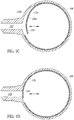
- a second end 124 of the bi-material strip moves radially in the directions indicated by the arrows between an open state, as shown in Figures 1B and 1C , in which the fluid, in either the liquid or gas state, can move between the connecting tube 110 and the condenser 108, and a closed state, as shown in Figure ID, in which the fluid is blocked from moving between the connecting tube 110 and the condenser 108.
- the valve 120 is a passive valve that changes state in response to being exposed to environmental temperature changes, such as in response to changes in temperature in the condenser 108. For instance, as the temperature in the condenser 108 increases to a threshold, the bi-material strip increases in temperature to cause the materials forming the bi-material strip to expand such that the movable end 124 uncoils so that the movable end 124 presses against the inner surface of the condenser 108 over the port 122, thereby fluidly separating the condenser 108 from the rest of the thermosiphon 104.
- the bi-material strip decreases in temperature to cause the materials forming the bi-material strip to contract such that the movable end 124 coils to a position as shown in Figure 1C , thereby uncovering the port 122 and fluidly coupling the condenser 108 with the rest of the thermosiphon 104.
- the heat source heats the calibration unit 102, which heats the fluid in the evaporator 106 of the thermosiphon 104, thereby causing the fluid to vaporize.
- the vaporized fluid rises and travels, in vapor form, from the evaporator 106 through the connecting tube 110 into the condenser 108.
- the condenser 108 the vaporized fluid is cooled and condensed into liquid form. In the liquid form, the fluid travels with gravity through the connecting tube 110 to the evaporator 106 at the calibration unit 102.
- the calibration unit 102 may again heat the liquid in the evaporator 106, turning the liquid back into the vapor form, which again is provided back to the condenser 108 through the connecting tube 110. The cycle continues until a desired temperature of the calibration unit 102 is achieved and held.
- the cooling assembly 114 such as a Stirling cooler
- the cooling assembly 114 has limited heat sink abilities, thereby limiting the amount the cooling assembly aids in cooling the vaporized fluid in the condenser 108.
- components of the cooling assembly in the illustrated embodiment, the Stirling cooler
- the elevated temperatures can be damaged by the elevated temperatures, such as temperatures at or above 50°C.
- the increased temperatures result in increased pressure, which can cause fatigue and failure of various components of the Stirling cooler.
- the bi-material strip of the valve 120 is constructed such that the movable end 124 of the bi-material strip expands and radially moves into the closed state and decouples the condenser 108 from the rest of the thermosiphon 104, as shown in Figure ID.
- a predetermined threshold value such as 50°C
- the movable end 124 of the bi-material strip of the valve 120 retracts and moves radially into the open state, as shown in Figure 1C .
- thermosiphon 104 By providing a valve 120 in the thermosiphon 104 that fluidly isolates the condenser 108 from the rest of the thermosiphon 104 when the thermosiphon 104 is operating at elevated temperatures, the temperature that the cooling assembly 114 is exposed to is thereby limited. Thus, the cooling assembly 114 may be protected from damage caused by high temperatures of the thermosiphon.
- the valve opens to thereby place the condenser in fluid communication with the rest of the thermosiphon.
- the natural state for the bi-material strip at ambient temperature is the closed state, as shown in Figure ID.
- the bi-material strip coils into the open state, as shown in Figure 1C .
- the valve 120 closes, thereby preventing the cooling assembly from being exposed to temperatures at or above ambient.
- the bi-material strip may include more than two materials so long as at least two of the materials are thermally conductive materials having suitably different CTEs that cause the valve 120 to open and close at desired temperatures.
- the first material may be stainless steel and the second material may be copper, which may be formed by press heating the first and second materials together.
- the size and shape of the bi-material strip may vary, depending on the materials being used for the bi-material strip and the temperatures at which the valve 120 is to open and close.
- the valve 120 is a bi-material strip that is electrically actuated, rather than passively actuated as described above.
- the bi-material strip is electrically coupled to an actuation device, such as a controller, that is configured to electrically activate the bi-material strip. For instance, a current may be applied to the bi-material strip that heats the bi-material strip to a particular temperature that would cause the bi-material strip to expand and cover the port 122 of the condenser 108.
- the electrically actuated bi-material strip may then be used in systems that use fluids in various temperature ranges, such as those that would not cause passive activation of the bi-material strip.
- the temperature calibration system 100 may include a pressure equalization port 132 that maintains fluid communication between the condenser 108 and the rest of the thermosiphon 104 for the purpose of maintaining an equalized pressure within the fluidic system.
- the pressure equalization port 132 allows some fluid communication between the condenser 108 and the rest of the thermosiphon 104 but is primarily for the purpose of reducing built up pressure within the fluidic system, particularly pressure that builds up in the rest of the thermosiphon 104.
- the temperature calibration system 100 may further include a port 126 at the top of the condenser 108.
- the port 126 may be used to refill the fluid in the system.
- the port 126 is closed or may be coupled to an expansion tank (not shown) that allows the gas to migrate through the port 126 to the expansion tank, which is located below the condenser 108.
- an expansion tank not shown
- the gas migrates back to the condenser 108 and the thermosiphon 104 continues to operate as usual.
- FIGS 2A and 2B show a valve 120a in accordance with another embodiment, for use in a temperature calibration system such as the temperature calibration system 100 of Figure 1A .
- the valve 120a is a strip that is made from a single material or alloy.
- the strip is circumferentially shaped and extends substantially around and abuts the inner surface of the condenser 108.
- a fixed end 130 of the single strip is fixed to the inner surface of the condenser 108 by a fixing element, such as by a pin 128, a screw, an adhesive, or any other suitable fixing structure.
- the movable end 124 of the valve 120a is opposite the fixed end 130, and is configured to move in directions indicated by the arrows in Figures 2A and 2B in response to the material expanding and contracting due to changes in temperature.
- the single strip valve 120a expands until the movable end 124 covers the port 122 of the condenser 108 to the closed position, as shown in Figure 2B .
- the single strip valve 120a contracts until the movable end 124 moves away from the port 122 of the condenser 108 to the opened position, as shown in Figure 2A .
- the single strip material is made from copper or a copper alloy. The single strip may also be electrically actuated in a similar manner as discussed above in reference to the bi-material strip of valve 120.
- FIGS 3A-3C show a valve 120b in accordance with another embodiment, for use in a temperature calibration system such as the temperature calibration system 100 of Figure 1A .
- the valve 120b of Figures 3A-3C is substantially similar in function and structure to the valve 120a shown in Figures 2A and 2B , and thus only the differences will be described.
- the valve 120b of Figures 3A-3C is a folded strip that has concertina folds or zig-zag folds, as best shown in Figures 3B and 3C .
- the fixed end 130 of the folded strip is fixed to the inner surface of the condenser 108 opposite the port 122 of the condenser 108 and the movable end 124 has an end portion that is suitably sized to cover the port 122.
- the folded strip moves axially in the directions indicated by the arrows. That is, the folded strip expands to a closed state, as shown in Figure 3C , and retracts to an open state, as shown in Figure 3B .
- the folded strip may be actuated passively or actively as discussed above.
- the folded strip axially expands in response to increasing to a temperature that causes the movable end 124 of the folded strip to abut the condenser 108 covering the port 122 and thereby placing the valve 120b in the closed state, as shown in Figure 3C .
- the folded strip In response to decreasing in temperature, the folded strip axially contracts, causing the movable end 124 of the folded strip to retract from the port 122 and thereby placing the valve in the open state, as shown in Figure 3B .
- the folded strip expands in response to current or voltage being applied to the strip.
- the folded strip may be a single material, alloy, or plurality of materials.
- the folded strip is a metal material, such as copper.
- the dimensions of the folded strip, such as length and thickness, depend on the material(s) or alloy(s) used for the folded strip.
- the movable end 124 is shown as a flat plate, the movable end 124 may any suitable shape the covers the port 122 of the condenser 108, such as a sphere, rectangular block, etc. Additionally, in some embodiments, the condenser 108 may include one or more guides that help maintain the position of the movable end 124 relative to the port 122 to ensure that expansion of the valve 120b suitably causes the movable end 124 to cover the port 122.
- FIGS 4A and 4B show a valve 120c in accordance with another embodiment, for use in a temperature calibration system such as the temperature calibration system 100 of Figure 1A .
- the valve 120c of Figures 4A and 4B is a solenoid valve that is electrically actuated.
- the valve 120c is activated by receiving electrical signals from an actuation device, such as a controller.
- the valve 120c is located inside the condenser 108.
- the valve 120c may be external to the condenser 108, such as in the connecting tube 110 of the thermosiphon 104 proximate the port 122 of the condenser 108.
- valve 120c depicted in Figures 4A and 4B includes an end that radially extends from a solenoid base to cover the port 122, other suitable configurations of the valve 120c may include an end that extends circumferentially from the solenoid base to cover the port 122.
- FIG. 5 is a block diagram illustrating some of the electrical components of the temperature calibration system 100 in accordance with at least one embodiment.
- the temperature calibration system 100 includes a controller 150 coupled to a heat source 152, a cooling assembly 114, a user interface 156, a power source 158, and at least one temperature sensor 160.
- the temperature calibration system 100 may further include an electrically actuated valve 162 that is coupled to the controller 150.
- the electrically actuated valve 162 may be any of the valves described herein, including valves 120, 120a, 120b, and 120c.
- the user interface 156 may include various inputs such as a touchscreen display, keyboard, knobs and buttons that allow a user to interact with the controller 150, and outputs, such as a display and lights, for communicating with the user. For instance, the user may input a desired temperature for the calibration unit 102, which is provided to the controller 150.
- the controller 150 which may be a microprocessor or other programmed or wired circuitry, includes suitable circuitry and logic for performing various functions during the operation of the temperature calibration system 100.
- the controller 150 is configured to activate and deactivate the heat source 152, the cooling assembly 114, and the electrically actuated valve 162.
- the controller 150 may send a signal to the heat source 152 to activate the heat source 152.
- a temperature sensor 160 is configured to provide a temperature signal to the controller 150.
- the temperature sensor 160 is located inside of the thermosiphon 104, such as in the condenser 108, and is configured to sense the temperature within the thermosiphon 104 or condenser 108.
- the controller 150 is configured to compare the sensed temperature to one or more thresholds. In response to sensing a temperature that is above a first threshold, the controller 150 may activate the cooling assembly 114. In response to sensing a temperature that is above a second threshold, controller 150 may close the valve 162 to fluidly decouple the condenser 108 from the rest of the thermosiphon 104.
- the controller 150 includes suitable circuitry and logic to provide a signal to the electrically activated valve 162 that causes the valve 162 to move from the open state to the closed state, thereby fluidly decoupling the condenser 108 from the rest of the thermosiphon 104.
- the second threshold may be a temperature that is less than a temperature that would otherwise damage a component of the cooling assembly 114, which may be a Stirling cooler. In at least one embodiment, the second threshold is between 50°C and 60°C.
- the controller 150 may receive a temperature signal and determine that the sensed temperature is below the second threshold. In response, the controller 150 is configured to provide a second signal to the electronic valve 162 to cause the valve 162 to move from the closed state to the open state, thereby fluidly coupling the condenser 108 to the rest of the thermosiphon 104.
- the threshold used to open the electrically activated valve 162 may be different than the threshold used to close the electrically activated valve 162.
- the power source which can be a battery or a plug for coupling to a main power supply, provides power for operating the temperature calibration system.
- valves located inside the condenser it should be understood that the valves may be located in other locations within the closed fluidic system.
- the valve may be located anywhere in the connecting tube, such as in the connecting tube proximate the condenser.
- valves may have a natural state that places the valve in the closed state.
- the condenser is fluidly separated from the rest of the thermosiphon.
- any of the passively actuated valves may be electrically actuated instead.
- any of the passively actuated valves may be used to operate at different environmental temperatures within the closed system than would activate the valves based on the material properties of the material(s) that make up the valve.
- thermosiphon is described in the exemplary embodiments provided herein, a person of ordinary skill in the art understands any reference to a thermosiphon in accordance with the present disclosure may also apply to a heat pipe.
- Examples provide a temperature calibration system comprising: a calibration unit configured to receive one or more device elements to be calibrated; and a closed fluidic system configured to remove heat from the calibration unit, the closed fluidic system including a condenser and an evaporator, the closed fluidic system including a valve configured to fluidly decouple the condenser from the evaporator in a closed state and to fluidly couple the condenser to the evaporator in an open state.
- valve is located inside of the condenser and configured to cover a port of the condenser in the closed state.
- the valve is a passive valve that expands and contracts to move between the closed state and the open state in response to changes in temperature.
- the valve is a bi-material strip that includes a first material coupled to a second material, the first material having a different coefficient of thermal expansion than the second material.
- the bi-material strip has a movable end that moves radially between the open state and the closed state.
- the valve has a first end that is fixed to an inner surface of the condenser and a second end that is configured to expand and contract to place the valve in the closed state and the open state, respectively.
- the valve is configured to be actuated in response to receiving an electrical signal.
- Some examples further comprise a cooling assembly coupled to the condenser of the closed fluidic system, the cooling assembly being configured to cool the condenser.
- Examples also provide a temperature calibration system comprising: a calibration unit; an evaporator on the calibration unit, the evaporator having a port; a condenser having a port; a connecting tube having a first end coupled to the port of the evaporator and a second end coupled to the port of the condenser; a valve located in the condenser, the valve being configured to move between an open state that fluidly couples the condenser with the connecting tube, and a closed state that fluidly decouples the condenser from the connecting tube; and a cooling assembly coupled to the condenser.
- the valve moves between the open state and the closed state in response to changes in temperature that cause a portion of the valve to move between the open state and closed state.
- the valve is a strip located around an inner surface of the condenser, the strip including a movable end that when in the closed state covers the port of the condenser.
- the movable end of the strip is curled inward and spaced from the inner surface of the condenser in the open state.
- the movable end of the strip abuts the inner surface of the condenser in the open state.
- the valve includes at least one thermally conductive material that includes a first end fixed to the condenser and a movable end that is movable and is configured to move the valve between the open state and the closed state in response to temperature changes inside of the condenser.
- Examples also provide a method comprising: heating a calibration unit; using a thermosiphon or heat pipe to remove heat from the calibration unit, the thermosiphon or heat pipe including a condenser and an evaporator; and in response to an increase in temperature above a threshold, fluidly decoupling the condenser from the evaporator.
- fluidly decoupling the condenser from the evaporator comprises closing a valve at a port of the condenser to fluidly decouple the condenser from the evaporator.
- fluidly decoupling the condenser from the evaporator comprises thermally expanding a material to cause a port of the condenser to be fluidly decoupled from the evaporator.
- fluidly decoupling the condenser from the evaporator comprises providing an electrical signal to a valve to cause the valve to fluidly decouple the condenser from the evaporator.
- the valve moves radially, circumferentially, or linearly in response to receiving the electrical signal.
- Some examples further comprise, in response to a decrease in pressure below the threshold, fluidly coupling the condenser to the evaporator.
Landscapes
- Engineering & Computer Science (AREA)
- General Engineering & Computer Science (AREA)
- Physics & Mathematics (AREA)
- Mechanical Engineering (AREA)
- General Physics & Mathematics (AREA)
- Life Sciences & Earth Sciences (AREA)
- Sustainable Development (AREA)
- Thermal Sciences (AREA)
- Cooling Or The Like Of Semiconductors Or Solid State Devices (AREA)
Abstract
Description
- Embodiments are directed to a temperature calibration system that utilizes a closed fluidic system, such as a thermosiphon or heat pipe.
- Many temperature calibration systems utilize a closed fluidic system for removing heat from a calibration unit. Typically, the closed fluidic system is a thermosiphon (or a heat pipe) that transfers fluid in the closed system between a liquid state and a vapor state. Thermosiphons may further be coupled to a cooling assembly to aid in removing heat from the calibration unit. In general, thermosiphons and cooling assemblies perform well when operating at cold temperatures that are below ambient but are limited when operating at higher temperatures, such as temperatures above ambient. At these higher temperatures, pressure in the system can cause damage to the cooling assemblies used to cool the thermosiphon.
- To prevent damage to the cooling assembly, some existing temperature calibration systems have limited the upper temperature limit of the operating ranges of the system. Other temperature calibration systems utilize an expansion tank that is in fluid communication with a condenser of the thermosiphon. As fluid in the thermosiphon rises above a threshold temperature, fluid in a gas state migrates through a port at an upper end of the condenser to the expansion tank, which is located below the condenser. When temperatures in the condenser reduce, the gas migrates back to the condenser and the thermosiphon continues to operate as usual. Alternative solutions, however, are desired.
- Embodiments described herein are directed to a temperature calibration system that includes a closed fluidic system, such as a thermosiphon or a heat pipe. The closed fluidic system includes a valve for fluidly separating components therein from each other. In one embodiment, the closed fluidic system is a thermosiphon (or heat pipe) and the valve is configured, in a closed state, to cover a port of the condenser to fluidly separate the condenser from other components of the thermosiphon. The valve may be a passively activated valve or an actively actuated valve (e.g., an electrically actuated valve). In some embodiments, the valve is thermally actuated such that the valve changes state in response to changes in temperature.
- In one embodiment is directed to a temperature calibration system comprising a calibration unit configured to receive one or more device elements to be calibrated. The temperature calibration system further includes a closed fluidic system configured to remove heat from the calibration unit. The closed fluidic system includes a condenser, an evaporator, and a valve. The valve is configured to fluidly decouple the condenser from the evaporator in a closed state and to fluidly couple the condenser to the evaporator in an open state.
- Another embodiment is directed to a temperature calibration system comprising a calibration unit, an evaporator on the calibration unit, and a condenser. The evaporator has a port and the condenser has a port. The temperature calibration system further includes a connecting tube having a first end coupled to the port of the evaporator and a second end coupled to the port of the condenser. A valve is located in the condenser. The valve is configured to move between an open state that fluidly couples the condenser with the connecting tube and a closed state that fluidly decouples the condenser from the connecting tube. The temperature calibration system further includes a cooling assembly coupled to the condenser.
- Another embodiment is directed to a method comprising heating a calibration unit and using a thermosiphon or heat pipe to remove heat from the calibration unit. The thermosiphon or heat pipe includes a condenser and an evaporator. The method further includes in response to an increase in temperature above a threshold, fluidly decoupling the condenser from the evaporator.
- In the drawings, identical reference numbers identify similar elements or acts. The sizes and relative positions of elements in the drawings are not necessarily drawn to scale. For example, the shapes of various elements and angles are not necessarily drawn to scale, and some of these elements may be arbitrarily enlarged and positioned to improve drawing legibility. Further, the particular shapes of the elements as drawn, are not necessarily intended to convey any information regarding the actual shape of the particular elements, and may have been solely selected for ease of recognition in the drawings.
-
Figure 1A is a schematic illustration of a temperature calibration system in accordance with one embodiment. -
Figure 1B is a close-up view of a portion of a thermosiphon in the temperature calibration system ofFigure 1A in accordance with one embodiment. -
Figures 1C and 1D are cross-section views of the portion of the thermosiphon ofFigure 1B with a valve in an open state and a closed state, respectively. -
Figures 2A and 2B are cross-section views of a portion of a thermosiphon with a valve in accordance with another embodiment. -
Figure 3A is a close-up view of a portion of a thermosiphon with a valve in accordance with another embodiment. -
Figures 3B and 3C are cross-section views of the portion of the thermosiphon ofFigure 3A with the valve in an open state and a closed state, respectively. -
Figures 4A and 4B are cross-section views of a portion of a thermosiphon with a valve in accordance with another embodiment in an open state and a closed state, respectively. -
Figure 5 is a block diagram illustrating some of the electrical components of the temperature calibration system ofFigure 1A . - In the following description, certain specific details are set forth in order to provide a thorough understanding of various disclosed embodiments. However, one skilled in the relevant art will recognize that implementations may be practiced without one or more of these specific details, or with other methods, components, materials, etc. In other instances, well-known structures of the temperature calibration systems have not been shown or described in detail to avoid unnecessarily obscuring descriptions of the embodiments.
- Embodiments are directed to a temperature calibration system that includes a closed fluidic system, such as a thermosiphon or a heat pipe. The closed fluidic system includes a valve for fluidly separating components therein from each other. In one embodiment, the closed fluidic system is a thermosiphon (or heat pipe) and the valve is configured, in a closed state, to cover a port of the condenser to fluidly separate the condenser from other components of the thermosiphon. The valve may be a passively activated valve or an actively actuated valve (e.g., an electrically actuated valve). In some embodiments, the valve is thermally actuated such that the valve changes state in response to changes in temperature.
-
Figures 1A-1D show atemperature calibration system 100 in accordance with one embodiment. Thetemperature calibration system 100 includes acalibration unit 102 that provides a chamber with a controlled temperature over a temperature range. Thetemperature calibration system 100 includes a heat source 152 (Figure 5 ) for heating thecalibration unit 102 and a closed fluidic system, such as athermosiphon 104 or heat pipe, for removing heat from thecalibration unit 102. - In some embodiments, the
calibration unit 102 is a dry block assembly that includes a thermally conductive material, such as a metal, and includes one or more openings for receiving one or more device elements to be calibrated, such as probes or thermometers. In other embodiments, thecalibration unit 102 includes a liquid bath that is heated by the heat source. - The
heat source 152 is any heat source configured to heat thecalibration unit 102. In some embodiments, the heat sources may be Peltier elements, electrodes, cartridge heaters, or any other suitable heater(s) configured to heat thecalibration unit 102. - Heat is transferred away from the
calibration unit 102 by thethermosiphon 104. Thethermosiphon 104 includes anevaporator 106 that is located at thecalibration unit 102, acondenser 108 that is separated from thecalibration unit 102, and a connectingtube 110 that places theevaporator 106 in fluid communication with thecondenser 108. In particular, afirst end 110a of the connectingtube 110 is coupled to a port of theevaporator 106 at thecalibration unit 102, and asecond end 110b of the connectingtube 110 is coupled to aport 122 of the condenser 108 (seeFigure 1B ). Theevaporator 106, thecondenser 108, and the connectingtube 110 together are a closed system containing a fluid therein. Theevaporator 106 is configured to allow heat in thecalibration unit 102 to transfer to the fluid, which is in a liquid form, and to cause the heated liquid to evaporate into gas. Thecondenser 108 is configured to cool the fluid in the gas form to cause the fluid to condense into a liquid form. The fluid in the various forms moves through the connectingtube 110 between theevaporator 106 and thecondenser 108. The fluid may be any fluid or refrigerant, including water, acetone, methanol, or any other suitable fluid. - To aid the
condenser 108 in cooling the fluid, thetemperature calibration system 100 further includes acooling assembly 114 that is coupled to thecondenser 108. The coolingassembly 114 acts as a heat sink to remove heat from thecondenser 108 to aid thecondenser 108 in converting the fluid in gas form therein into liquid form. The coolingassembly 114 in the illustrated embodiment is a Stirling cooler and includes acooling head 116 that is thermally coupled to thecondenser 108. The heat transfers from thecondenser 108 to thecooling head 116 and through the remaining parts of the coolingassembly 114. - As best shown in
Figures 1B-1D , thethermosiphon 104 includes avalve 120 that fluidly couples and decouples thecondenser 108 from the rest of thethermosiphon 104. In the illustrated embodiment, thevalve 120 is located inside thecondenser 108 and is configured to fluidly close or open aport 122 of thecondenser 108 at thesecond end 110b of the connectingtube 110. - In the illustrated embodiment, the
valve 120 is a bi-material strip of two thermally conductive materials coupled together such that a first thermally conductive material is provided on aninner side 120a and a second thermally conductive material is provided on anouter side 120b. The two materials have different coefficients of thermal expansion (CTE), and thus expand and contract at different rates and temperatures to cause thevalve 120 to change states from the open state to the closed state. In at least one embodiment, the first thermally conductive material at theinner side 120a has a CTE that is greater than the CTE of the second thermally conductive material at the outer side. - The bi-material strip that forms the
valve 120 has a circumferential shape that includes a first portion that rests on the inner wall of thecondenser 108. Asecond end 124 of the bi-material strip moves radially in the directions indicated by the arrows between an open state, as shown inFigures 1B and1C , in which the fluid, in either the liquid or gas state, can move between the connectingtube 110 and thecondenser 108, and a closed state, as shown in Figure ID, in which the fluid is blocked from moving between the connectingtube 110 and thecondenser 108. In particular, in the open state, themovable end 124 coils inward as shown inFigure 1C , and in the closed state, themovable end 124 rests against the inner wall of thecondenser 108 surrounding theport 122 of thecondenser 108, as shown in Figure ID. - In at least one embodiment, the
valve 120 is a passive valve that changes state in response to being exposed to environmental temperature changes, such as in response to changes in temperature in thecondenser 108. For instance, as the temperature in thecondenser 108 increases to a threshold, the bi-material strip increases in temperature to cause the materials forming the bi-material strip to expand such that themovable end 124 uncoils so that themovable end 124 presses against the inner surface of thecondenser 108 over theport 122, thereby fluidly separating thecondenser 108 from the rest of thethermosiphon 104. As the temperature in thecondenser 108 decreases below the threshold, the bi-material strip decreases in temperature to cause the materials forming the bi-material strip to contract such that themovable end 124 coils to a position as shown inFigure 1C , thereby uncovering theport 122 and fluidly coupling thecondenser 108 with the rest of thethermosiphon 104. - In operation of the
temperature calibration system 100, the heat source heats thecalibration unit 102, which heats the fluid in theevaporator 106 of thethermosiphon 104, thereby causing the fluid to vaporize. The vaporized fluid rises and travels, in vapor form, from theevaporator 106 through the connectingtube 110 into thecondenser 108. In thecondenser 108, the vaporized fluid is cooled and condensed into liquid form. In the liquid form, the fluid travels with gravity through the connectingtube 110 to theevaporator 106 at thecalibration unit 102. Thecalibration unit 102 may again heat the liquid in theevaporator 106, turning the liquid back into the vapor form, which again is provided back to thecondenser 108 through the connectingtube 110. The cycle continues until a desired temperature of thecalibration unit 102 is achieved and held. - In the event the
temperature calibration system 100 is operating at elevated temperatures, such as temperatures above ambient, the coolingassembly 114, such as a Stirling cooler, has limited heat sink abilities, thereby limiting the amount the cooling assembly aids in cooling the vaporized fluid in thecondenser 108. Furthermore, components of the cooling assembly (in the illustrated embodiment, the Stirling cooler) can be damaged by the elevated temperatures, such as temperatures at or above 50°C. In particular, the increased temperatures result in increased pressure, which can cause fatigue and failure of various components of the Stirling cooler. - As the temperature increases above a predetermined threshold value, such as 50°C, the bi-material strip of the
valve 120 is constructed such that themovable end 124 of the bi-material strip expands and radially moves into the closed state and decouples thecondenser 108 from the rest of thethermosiphon 104, as shown in Figure ID. In response to the temperature inside thecondenser 108 decreasing below the predetermined threshold value, themovable end 124 of the bi-material strip of thevalve 120 retracts and moves radially into the open state, as shown inFigure 1C . - By providing a
valve 120 in thethermosiphon 104 that fluidly isolates thecondenser 108 from the rest of thethermosiphon 104 when thethermosiphon 104 is operating at elevated temperatures, the temperature that the coolingassembly 114 is exposed to is thereby limited. Thus, the coolingassembly 114 may be protected from damage caused by high temperatures of the thermosiphon. When the temperature of the thermosiphon, such as inside of the condenser, decreases below a predetermined threshold, the valve opens to thereby place the condenser in fluid communication with the rest of the thermosiphon. - In at least one embodiment, the natural state for the bi-material strip at ambient temperature is the closed state, as shown in Figure ID. As temperatures in the condenser go below ambient, the bi-material strip coils into the open state, as shown in
Figure 1C . Thus, as temperatures increase to ambient, thevalve 120 closes, thereby preventing the cooling assembly from being exposed to temperatures at or above ambient. - The bi-material strip may include more than two materials so long as at least two of the materials are thermally conductive materials having suitably different CTEs that cause the
valve 120 to open and close at desired temperatures. For instance, in one embodiment the first material may be stainless steel and the second material may be copper, which may be formed by press heating the first and second materials together. The size and shape of the bi-material strip may vary, depending on the materials being used for the bi-material strip and the temperatures at which thevalve 120 is to open and close. - In another embodiment, the
valve 120 is a bi-material strip that is electrically actuated, rather than passively actuated as described above. In this embodiment, the bi-material strip is electrically coupled to an actuation device, such as a controller, that is configured to electrically activate the bi-material strip. For instance, a current may be applied to the bi-material strip that heats the bi-material strip to a particular temperature that would cause the bi-material strip to expand and cover theport 122 of thecondenser 108. The electrically actuated bi-material strip may then be used in systems that use fluids in various temperature ranges, such as those that would not cause passive activation of the bi-material strip. - As shown in
Figure 1B , thetemperature calibration system 100 may include apressure equalization port 132 that maintains fluid communication between thecondenser 108 and the rest of thethermosiphon 104 for the purpose of maintaining an equalized pressure within the fluidic system. Thus, even though thevalve 120 is in the closed state, as shown in Figure ID, thepressure equalization port 132 allows some fluid communication between thecondenser 108 and the rest of thethermosiphon 104 but is primarily for the purpose of reducing built up pressure within the fluidic system, particularly pressure that builds up in the rest of thethermosiphon 104. - The
temperature calibration system 100 may further include aport 126 at the top of thecondenser 108. Theport 126 may be used to refill the fluid in the system. During operation, theport 126 is closed or may be coupled to an expansion tank (not shown) that allows the gas to migrate through theport 126 to the expansion tank, which is located below thecondenser 108. When temperature in thecondenser 108 reduces, the gas migrates back to thecondenser 108 and thethermosiphon 104 continues to operate as usual. -
Figures 2A and 2B show avalve 120a in accordance with another embodiment, for use in a temperature calibration system such as thetemperature calibration system 100 ofFigure 1A . - The
valve 120a is a strip that is made from a single material or alloy. The strip is circumferentially shaped and extends substantially around and abuts the inner surface of thecondenser 108. Afixed end 130 of the single strip is fixed to the inner surface of thecondenser 108 by a fixing element, such as by apin 128, a screw, an adhesive, or any other suitable fixing structure. Themovable end 124 of thevalve 120a is opposite thefixed end 130, and is configured to move in directions indicated by the arrows inFigures 2A and 2B in response to the material expanding and contracting due to changes in temperature. That is, in response to the temperature increasing to a threshold, thesingle strip valve 120a expands until themovable end 124 covers theport 122 of thecondenser 108 to the closed position, as shown inFigure 2B . As the temperature decreases to below a threshold value, thesingle strip valve 120a contracts until themovable end 124 moves away from theport 122 of thecondenser 108 to the opened position, as shown inFigure 2A . In at least one embodiment, the single strip material is made from copper or a copper alloy. The single strip may also be electrically actuated in a similar manner as discussed above in reference to the bi-material strip ofvalve 120. -
Figures 3A-3C show avalve 120b in accordance with another embodiment, for use in a temperature calibration system such as thetemperature calibration system 100 ofFigure 1A . Thevalve 120b ofFigures 3A-3C is substantially similar in function and structure to thevalve 120a shown inFigures 2A and 2B , and thus only the differences will be described. - The
valve 120b ofFigures 3A-3C is a folded strip that has concertina folds or zig-zag folds, as best shown inFigures 3B and 3C . Thefixed end 130 of the folded strip is fixed to the inner surface of thecondenser 108 opposite theport 122 of thecondenser 108 and themovable end 124 has an end portion that is suitably sized to cover theport 122. The folded strip moves axially in the directions indicated by the arrows. That is, the folded strip expands to a closed state, as shown inFigure 3C , and retracts to an open state, as shown inFigure 3B . - The folded strip may be actuated passively or actively as discussed above. In particular, the folded strip axially expands in response to increasing to a temperature that causes the
movable end 124 of the folded strip to abut thecondenser 108 covering theport 122 and thereby placing thevalve 120b in the closed state, as shown inFigure 3C . In response to decreasing in temperature, the folded strip axially contracts, causing themovable end 124 of the folded strip to retract from theport 122 and thereby placing the valve in the open state, as shown inFigure 3B . In the embodiment in which the valve is actively actuated, the folded strip expands in response to current or voltage being applied to the strip. - The folded strip may be a single material, alloy, or plurality of materials. In at least one embodiment, the folded strip is a metal material, such as copper. The dimensions of the folded strip, such as length and thickness, depend on the material(s) or alloy(s) used for the folded strip. Although the
movable end 124 is shown as a flat plate, themovable end 124 may any suitable shape the covers theport 122 of thecondenser 108, such as a sphere, rectangular block, etc. Additionally, in some embodiments, thecondenser 108 may include one or more guides that help maintain the position of themovable end 124 relative to theport 122 to ensure that expansion of thevalve 120b suitably causes themovable end 124 to cover theport 122. -
Figures 4A and 4B show avalve 120c in accordance with another embodiment, for use in a temperature calibration system such as thetemperature calibration system 100 ofFigure 1A . Thevalve 120c ofFigures 4A and 4B is a solenoid valve that is electrically actuated. In particular, thevalve 120c is activated by receiving electrical signals from an actuation device, such as a controller. In the illustrated embodiments, thevalve 120c is located inside thecondenser 108. However, in other embodiments, thevalve 120c may be external to thecondenser 108, such as in the connectingtube 110 of thethermosiphon 104 proximate theport 122 of thecondenser 108. - By having a valve configured to fluidly decouple the
condenser 108 from theevaporator 106 of thethermosiphon 104, components of thetemperature calibration system 100 may be protected from high temperatures and pressures that can cause damage. Thus, thetemperature calibration system 100 can withstand higher operating temperatures than temperature calibration systems that are otherwise known. While thevalve 120c depicted inFigures 4A and 4B includes an end that radially extends from a solenoid base to cover theport 122, other suitable configurations of thevalve 120c may include an end that extends circumferentially from the solenoid base to cover theport 122. -
Figure 5 is a block diagram illustrating some of the electrical components of thetemperature calibration system 100 in accordance with at least one embodiment. Thetemperature calibration system 100 includes acontroller 150 coupled to aheat source 152, a coolingassembly 114, auser interface 156, apower source 158, and at least onetemperature sensor 160. Thetemperature calibration system 100 may further include an electrically actuatedvalve 162 that is coupled to thecontroller 150. The electrically actuatedvalve 162 may be any of the valves described herein, includingvalves user interface 156 may include various inputs such as a touchscreen display, keyboard, knobs and buttons that allow a user to interact with thecontroller 150, and outputs, such as a display and lights, for communicating with the user. For instance, the user may input a desired temperature for thecalibration unit 102, which is provided to thecontroller 150. - The
controller 150, which may be a microprocessor or other programmed or wired circuitry, includes suitable circuitry and logic for performing various functions during the operation of thetemperature calibration system 100. Thecontroller 150 is configured to activate and deactivate theheat source 152, the coolingassembly 114, and the electrically actuatedvalve 162. In response to receiving the desired temperature from the user interface, thecontroller 150 may send a signal to theheat source 152 to activate theheat source 152. Atemperature sensor 160 is configured to provide a temperature signal to thecontroller 150. In at least one embodiment, thetemperature sensor 160 is located inside of thethermosiphon 104, such as in thecondenser 108, and is configured to sense the temperature within thethermosiphon 104 orcondenser 108. - The
controller 150 is configured to compare the sensed temperature to one or more thresholds. In response to sensing a temperature that is above a first threshold, thecontroller 150 may activate thecooling assembly 114. In response to sensing a temperature that is above a second threshold,controller 150 may close thevalve 162 to fluidly decouple thecondenser 108 from the rest of thethermosiphon 104. In particular, thecontroller 150 includes suitable circuitry and logic to provide a signal to the electrically activatedvalve 162 that causes thevalve 162 to move from the open state to the closed state, thereby fluidly decoupling thecondenser 108 from the rest of thethermosiphon 104. The second threshold may be a temperature that is less than a temperature that would otherwise damage a component of the coolingassembly 114, which may be a Stirling cooler. In at least one embodiment, the second threshold is between 50°C and 60°C. - Upon the cooling
assembly 114 cooling thecondenser 108, thecontroller 150 may receive a temperature signal and determine that the sensed temperature is below the second threshold. In response, thecontroller 150 is configured to provide a second signal to theelectronic valve 162 to cause thevalve 162 to move from the closed state to the open state, thereby fluidly coupling thecondenser 108 to the rest of thethermosiphon 104. In other embodiments, the threshold used to open the electrically activatedvalve 162 may be different than the threshold used to close the electrically activatedvalve 162. - The power source, which can be a battery or a plug for coupling to a main power supply, provides power for operating the temperature calibration system.
- While the foregoing description illustrates and describes valves located inside the condenser, it should be understood that the valves may be located in other locations within the closed fluidic system. For instance, the valve may be located anywhere in the connecting tube, such as in the connecting tube proximate the condenser.
- Although not described with each embodiment, it is to be appreciated that valves may have a natural state that places the valve in the closed state. Thus, in the event that power is not provided to the temperature calibration system, the condenser is fluidly separated from the rest of the thermosiphon. Furthermore, any of the passively actuated valves may be electrically actuated instead. In that regard, any of the passively actuated valves may be used to operate at different environmental temperatures within the closed system than would activate the valves based on the material properties of the material(s) that make up the valve.
- Although a thermosiphon is described in the exemplary embodiments provided herein, a person of ordinary skill in the art understands any reference to a thermosiphon in accordance with the present disclosure may also apply to a heat pipe.
- Examples provide a temperature calibration system comprising: a calibration unit configured to receive one or more device elements to be calibrated; and a closed fluidic system configured to remove heat from the calibration unit, the closed fluidic system including a condenser and an evaporator, the closed fluidic system including a valve configured to fluidly decouple the condenser from the evaporator in a closed state and to fluidly couple the condenser to the evaporator in an open state.
- In some examples, the valve is located inside of the condenser and configured to cover a port of the condenser in the closed state.
- In some examples, the valve is a passive valve that expands and contracts to move between the closed state and the open state in response to changes in temperature.
- In some examples, the valve is a bi-material strip that includes a first material coupled to a second material, the first material having a different coefficient of thermal expansion than the second material.
- In some examples, the bi-material strip has a movable end that moves radially between the open state and the closed state.
- In some examples, the valve has a first end that is fixed to an inner surface of the condenser and a second end that is configured to expand and contract to place the valve in the closed state and the open state, respectively.
- In some examples, the valve is configured to be actuated in response to receiving an electrical signal.
- Some examples further comprise a cooling assembly coupled to the condenser of the closed fluidic system, the cooling assembly being configured to cool the condenser.
- Examples also provide a temperature calibration system comprising: a calibration unit; an evaporator on the calibration unit, the evaporator having a port; a condenser having a port; a connecting tube having a first end coupled to the port of the evaporator and a second end coupled to the port of the condenser; a valve located in the condenser, the valve being configured to move between an open state that fluidly couples the condenser with the connecting tube, and a closed state that fluidly decouples the condenser from the connecting tube; and a cooling assembly coupled to the condenser.
- In some examples, the valve moves between the open state and the closed state in response to changes in temperature that cause a portion of the valve to move between the open state and closed state.
- In some examples, the valve is a strip located around an inner surface of the condenser, the strip including a movable end that when in the closed state covers the port of the condenser.
- In some examples, the movable end of the strip is curled inward and spaced from the inner surface of the condenser in the open state.
- In some examples, the movable end of the strip abuts the inner surface of the condenser in the open state.
- In some examples, the valve includes at least one thermally conductive material that includes a first end fixed to the condenser and a movable end that is movable and is configured to move the valve between the open state and the closed state in response to temperature changes inside of the condenser.
- Examples also provide a method comprising: heating a calibration unit; using a thermosiphon or heat pipe to remove heat from the calibration unit, the thermosiphon or heat pipe including a condenser and an evaporator; and in response to an increase in temperature above a threshold, fluidly decoupling the condenser from the evaporator.
- In some examples, fluidly decoupling the condenser from the evaporator comprises closing a valve at a port of the condenser to fluidly decouple the condenser from the evaporator.
- In some examples, fluidly decoupling the condenser from the evaporator comprises thermally expanding a material to cause a port of the condenser to be fluidly decoupled from the evaporator.
- In some examples, fluidly decoupling the condenser from the evaporator comprises providing an electrical signal to a valve to cause the valve to fluidly decouple the condenser from the evaporator.
- In some examples, the valve moves radially, circumferentially, or linearly in response to receiving the electrical signal.
- Some examples further comprise, in response to a decrease in pressure below the threshold, fluidly coupling the condenser to the evaporator.
- The various embodiments described above can be combined to provide further embodiments. These and other changes can be made to the embodiments in light of the above-detailed description. In general, in the following claims, the terms used should not be construed to limit the claims to the specific embodiments disclosed in the specification and the claims, but should be construed to include all possible embodiments along with the full scope of equivalents to which such claims are entitled. Accordingly, the claims are not limited by the disclosure.
Claims (15)
- A temperature calibration system comprising:a calibration unit configured to receive one or more device elements to be calibrated; anda closed fluidic system configured to remove heat from the calibration unit, the closed fluidic system including a condenser and an evaporator, the closed fluidic system including a valve configured to fluidly decouple the condenser from the evaporator in a closed state and to fluidly couple the condenser to the evaporator in an open state.
- The temperature calibration system of Claim 1, wherein the valve is located inside of the condenser and configured to cover a port of the condenser in the closed state.
- The temperature calibration system of Claims 1 or 2, wherein the valve is a passive valve that expands and contracts to move between the closed state and the open state in response to changes in temperature.
- The temperature calibration system of any of Claims 1 to 3, wherein the valve is a bi material strip that includes a first material coupled to a second material, the first material having a different coefficient of thermal expansion than the second material.
- The temperature calibration system of Claim 4, wherein the bi material strip has a movable end that moves radially between the open state and the closed state, wherein the movable end is configured to curl inward to be spaced from an inner surface of the condenser in the open state and is configured to curl outward to abut an inner surface of the condenser in the closed state.
- The temperature calibration system of any of Claims 1 to 4, wherein the valve has a first end that is fixed to an inner surface of the condenser and a second end that is configured to expand and contract to place the valve in the closed state and the open state, respectively.
- The temperature calibration system of any of Claims 1 to 6, wherein the valve is configured to be actuated in response to receiving an electrical signal.
- The temperature calibration system of any of Claims 1 to 7, further comprising a cooling assembly coupled to the condenser of the closed fluidic system, the cooling assembly being configured to cool the condenser.
- The temperature calibration system of any of Claims 1 to 8 wherein the closed fluidic system further comprises a connecting tube having a first end coupled to a port of the evaporator and a second end coupled to a port of the condenser.
- A method comprising:heating a calibration unit;using a thermosiphon or heat pipe to remove heat from the calibration unit, the thermosiphon or heat pipe including a condenser and an evaporator; andin response to an increase in temperature above a threshold, fluidly decoupling the condenser from the evaporator.
- The method of Claim 10, wherein fluidly decoupling the condenser from the evaporator comprises closing a valve at a port of the condenser to fluidly decouple the condenser from the evaporator.
- The method of Claim 10 or 11, wherein fluidly decoupling the condenser from the evaporator comprises thermally expanding a material to cause a port of the condenser to be fluidly decoupled from the evaporator.
- The method of Claims 10 or 11, wherein fluidly decoupling the condenser from the evaporator comprises providing an electrical signal to the valve to cause the valve to fluidly decouple the condenser from the evaporator.
- The method of Claim 13, wherein the valve moves radially, circumferentially, or linearly in response to receiving the electrical signal.
- The method of any of Claims 10 to 14, further comprising in response to a decrease in pressure below the threshold, fluidly coupling the condenser to the evaporator.
Applications Claiming Priority (1)
| Application Number | Priority Date | Filing Date | Title |
|---|---|---|---|
| US15/668,417 US10677369B2 (en) | 2017-08-03 | 2017-08-03 | Temperature calibration system comprising a valve in a closed fluidic system |
Publications (2)
| Publication Number | Publication Date |
|---|---|
| EP3438592A1 true EP3438592A1 (en) | 2019-02-06 |
| EP3438592B1 EP3438592B1 (en) | 2020-02-12 |
Family
ID=63144871
Family Applications (1)
| Application Number | Title | Priority Date | Filing Date |
|---|---|---|---|
| EP18187207.8A Active EP3438592B1 (en) | 2017-08-03 | 2018-08-03 | Temperature calibration system comprising a valve in a closed fluidic system |
Country Status (2)
| Country | Link |
|---|---|
| US (1) | US10677369B2 (en) |
| EP (1) | EP3438592B1 (en) |
Families Citing this family (1)
| Publication number | Priority date | Publication date | Assignee | Title |
|---|---|---|---|---|
| FR3097624A1 (en) * | 2019-06-21 | 2020-12-25 | Airbus Operations | HEAT EXCHANGER SYSTEM WITH A PASSIVE SYSTEM FOR FLOW CONTROL |
Citations (4)
| Publication number | Priority date | Publication date | Assignee | Title |
|---|---|---|---|---|
| US6390668B1 (en) * | 1998-12-11 | 2002-05-21 | Peter Albert Materna | Blackbody source using a heat pipe principle and transition region |
| WO2008034442A2 (en) * | 2006-09-18 | 2008-03-27 | Ametek Denmark A/S | Thermal calibrating system |
| US20090067475A1 (en) * | 2007-09-11 | 2009-03-12 | Isothermal Technology Limited | Temperature measuring device |
| FR2923604A1 (en) * | 2007-11-14 | 2009-05-15 | Fluke Corp | METHOD AND SYSTEM FOR OPEN LOOP CORRECTION OF THE VERTICAL GRADIENT OF A DRY WELL CALIBRATION OVEN |
Family Cites Families (14)
| Publication number | Priority date | Publication date | Assignee | Title |
|---|---|---|---|---|
| AT408532B (en) * | 1996-01-30 | 2001-12-27 | Greiner & Soehne C A | MOLDING DEVICE FOR AN EXTRUSION SYSTEM |
| US20010037880A1 (en) * | 1999-12-30 | 2001-11-08 | Max Aaron Solondz | Valved heat pipe and adaptive cooling system including the same |
| JP4033699B2 (en) | 2002-04-08 | 2008-01-16 | シャープ株式会社 | Loop thermosyphon and Stirling refrigerator |
| JP2006317013A (en) * | 2005-04-12 | 2006-11-24 | Denso Corp | Heat pipe and exhaust heat recovery device using the same |
| US20070163754A1 (en) * | 2006-01-19 | 2007-07-19 | Dionne, Marien & Associes Inc. | Thermosiphon having improved efficiency |
| JP2008039373A (en) * | 2006-07-14 | 2008-02-21 | Denso Corp | Exhaust heat recovery unit |
| GB0706700D0 (en) * | 2007-04-05 | 2007-05-16 | Thermomax Ltd | Heat pipe for a solar collector |
| US9897365B2 (en) * | 2011-12-14 | 2018-02-20 | Lg Electronics Inc. | Refrigerator, thermosyphon, and solenoid valve and method for controlling the same |
| CN107505826B (en) * | 2013-02-25 | 2020-06-30 | 精工电子有限公司 | Temperature compensation type balance wheel and manufacturing method thereof, clock movement and mechanical clock |
| US20170307301A1 (en) * | 2014-11-11 | 2017-10-26 | Dantherm Cooling A/S | Thermosiphon blocks and thermosiphon systems for heat transfer |
| WO2016141033A1 (en) * | 2015-03-02 | 2016-09-09 | Board Of Regents, The University Of Texas System | Systems and methods for thermally actuated flow control |
| FR3034179B1 (en) * | 2015-03-23 | 2018-11-02 | Centre National De La Recherche Scientifique | SOLAR DEVICE FOR AUTONOMOUS COLD PRODUCTION BY SOLID-GAS SORPTION. |
| US10060681B2 (en) * | 2015-09-25 | 2018-08-28 | University Of Louisville Research Foundation, Inc. | Heat pipe augmented passive solar heating system |
| WO2017066127A1 (en) * | 2015-10-12 | 2017-04-20 | Alliance For Sustainable Energy, Llc | Solar thermoelectricity via advanced latent heat storage |
-
2017
- 2017-08-03 US US15/668,417 patent/US10677369B2/en active Active
-
2018
- 2018-08-03 EP EP18187207.8A patent/EP3438592B1/en active Active
Patent Citations (4)
| Publication number | Priority date | Publication date | Assignee | Title |
|---|---|---|---|---|
| US6390668B1 (en) * | 1998-12-11 | 2002-05-21 | Peter Albert Materna | Blackbody source using a heat pipe principle and transition region |
| WO2008034442A2 (en) * | 2006-09-18 | 2008-03-27 | Ametek Denmark A/S | Thermal calibrating system |
| US20090067475A1 (en) * | 2007-09-11 | 2009-03-12 | Isothermal Technology Limited | Temperature measuring device |
| FR2923604A1 (en) * | 2007-11-14 | 2009-05-15 | Fluke Corp | METHOD AND SYSTEM FOR OPEN LOOP CORRECTION OF THE VERTICAL GRADIENT OF A DRY WELL CALIBRATION OVEN |
Also Published As
| Publication number | Publication date |
|---|---|
| EP3438592B1 (en) | 2020-02-12 |
| US10677369B2 (en) | 2020-06-09 |
| US20190040969A1 (en) | 2019-02-07 |
Similar Documents
| Publication | Publication Date | Title |
|---|---|---|
| CN103201476B (en) | Cooling device for internal combustion engine | |
| CN1328525C (en) | Poppet valve with heater | |
| US8337081B1 (en) | Sensor assembly for mounting a temperature sensor to a tank | |
| US9581144B2 (en) | Arrangement for adjusting a valve | |
| US20060070447A1 (en) | High-temperature reduced size manometer | |
| TWI784962B (en) | Thermosiphons for use with temperature-regulated storage devices | |
| EP3438592B1 (en) | Temperature calibration system comprising a valve in a closed fluidic system | |
| ITTO20130873A1 (en) | TWO-PHASE FLUID COOLING / HEATING CIRCUIT WITH TEMPERATURE SENSITIVE FLOW CONTROL VALVES | |
| DK2609801T3 (en) | Borehole measurement tool | |
| EP2074374B1 (en) | Thermal calibrating system | |
| CN102460334B (en) | Valve arrangement | |
| CN103677011A (en) | Control system applicable to wide temperature ranges of surface source black bodies under vacuum condition | |
| EP3489598B1 (en) | Negative pressure release port and refrigeration device | |
| CN106990268B (en) | Electrochemical comprehensive tester | |
| US10591366B2 (en) | Temperature calibration system with separable cooling assembly | |
| JP5240072B2 (en) | Thermal element and method for manufacturing thermal element | |
| US20140239078A1 (en) | Thermostat Control System with IR Sensor | |
| EP3441709A1 (en) | Temperature calibration system with a closed fluidic system | |
| CN104807897B (en) | Process analysis device of improved thermal stability | |
| KR101345776B1 (en) | Initial cooling prediction system and method of superconducting magnet | |
| CN110274734B (en) | Liquid leakage detection device, heating box and chromatographic analysis system | |
| JPH02125188A (en) | Double heat-sensitive cutoff valve | |
| KR101348603B1 (en) | Cryogenic temperature sensor calibrator | |
| CN203455105U (en) | Temperature sensor | |
| TWM517327U (en) | Temperature regulating device with freezing head |
Legal Events
| Date | Code | Title | Description |
|---|---|---|---|
| PUAI | Public reference made under article 153(3) epc to a published international application that has entered the european phase |
Free format text: ORIGINAL CODE: 0009012 |
|
| STAA | Information on the status of an ep patent application or granted ep patent |
Free format text: STATUS: THE APPLICATION HAS BEEN PUBLISHED |
|
| AK | Designated contracting states |
Kind code of ref document: A1 Designated state(s): AL AT BE BG CH CY CZ DE DK EE ES FI FR GB GR HR HU IE IS IT LI LT LU LV MC MK MT NL NO PL PT RO RS SE SI SK SM TR |
|
| AX | Request for extension of the european patent |
Extension state: BA ME |
|
| STAA | Information on the status of an ep patent application or granted ep patent |
Free format text: STATUS: REQUEST FOR EXAMINATION WAS MADE |
|
| 17P | Request for examination filed |
Effective date: 20190715 |
|
| RBV | Designated contracting states (corrected) |
Designated state(s): AL AT BE BG CH CY CZ DE DK EE ES FI FR GB GR HR HU IE IS IT LI LT LU LV MC MK MT NL NO PL PT RO RS SE SI SK SM TR |
|
| GRAP | Despatch of communication of intention to grant a patent |
Free format text: ORIGINAL CODE: EPIDOSNIGR1 |
|
| STAA | Information on the status of an ep patent application or granted ep patent |
Free format text: STATUS: GRANT OF PATENT IS INTENDED |
|
| INTG | Intention to grant announced |
Effective date: 20191009 |
|
| GRAS | Grant fee paid |
Free format text: ORIGINAL CODE: EPIDOSNIGR3 |
|
| GRAA | (expected) grant |
Free format text: ORIGINAL CODE: 0009210 |
|
| STAA | Information on the status of an ep patent application or granted ep patent |
Free format text: STATUS: THE PATENT HAS BEEN GRANTED |
|
| AK | Designated contracting states |
Kind code of ref document: B1 Designated state(s): AL AT BE BG CH CY CZ DE DK EE ES FI FR GB GR HR HU IE IS IT LI LT LU LV MC MK MT NL NO PL PT RO RS SE SI SK SM TR |
|
| REG | Reference to a national code |
Ref country code: GB Ref legal event code: FG4D |
|
| REG | Reference to a national code |
Ref country code: CH Ref legal event code: EP |
|
| REG | Reference to a national code |
Ref country code: AT Ref legal event code: REF Ref document number: 1232683 Country of ref document: AT Kind code of ref document: T Effective date: 20200215 |
|
| REG | Reference to a national code |
Ref country code: DE Ref legal event code: R096 Ref document number: 602018002401 Country of ref document: DE |
|
| REG | Reference to a national code |
Ref country code: IE Ref legal event code: FG4D |
|
| PG25 | Lapsed in a contracting state [announced via postgrant information from national office to epo] |
Ref country code: RS Free format text: LAPSE BECAUSE OF FAILURE TO SUBMIT A TRANSLATION OF THE DESCRIPTION OR TO PAY THE FEE WITHIN THE PRESCRIBED TIME-LIMIT Effective date: 20200212 Ref country code: FI Free format text: LAPSE BECAUSE OF FAILURE TO SUBMIT A TRANSLATION OF THE DESCRIPTION OR TO PAY THE FEE WITHIN THE PRESCRIBED TIME-LIMIT Effective date: 20200212 Ref country code: NO Free format text: LAPSE BECAUSE OF FAILURE TO SUBMIT A TRANSLATION OF THE DESCRIPTION OR TO PAY THE FEE WITHIN THE PRESCRIBED TIME-LIMIT Effective date: 20200512 |
|
| REG | Reference to a national code |
Ref country code: LT Ref legal event code: MG4D |
|
| REG | Reference to a national code |
Ref country code: NL Ref legal event code: MP Effective date: 20200212 |
|
| PG25 | Lapsed in a contracting state [announced via postgrant information from national office to epo] |
Ref country code: GR Free format text: LAPSE BECAUSE OF FAILURE TO SUBMIT A TRANSLATION OF THE DESCRIPTION OR TO PAY THE FEE WITHIN THE PRESCRIBED TIME-LIMIT Effective date: 20200513 Ref country code: BG Free format text: LAPSE BECAUSE OF FAILURE TO SUBMIT A TRANSLATION OF THE DESCRIPTION OR TO PAY THE FEE WITHIN THE PRESCRIBED TIME-LIMIT Effective date: 20200512 Ref country code: HR Free format text: LAPSE BECAUSE OF FAILURE TO SUBMIT A TRANSLATION OF THE DESCRIPTION OR TO PAY THE FEE WITHIN THE PRESCRIBED TIME-LIMIT Effective date: 20200212 Ref country code: LV Free format text: LAPSE BECAUSE OF FAILURE TO SUBMIT A TRANSLATION OF THE DESCRIPTION OR TO PAY THE FEE WITHIN THE PRESCRIBED TIME-LIMIT Effective date: 20200212 Ref country code: SE Free format text: LAPSE BECAUSE OF FAILURE TO SUBMIT A TRANSLATION OF THE DESCRIPTION OR TO PAY THE FEE WITHIN THE PRESCRIBED TIME-LIMIT Effective date: 20200212 Ref country code: IS Free format text: LAPSE BECAUSE OF FAILURE TO SUBMIT A TRANSLATION OF THE DESCRIPTION OR TO PAY THE FEE WITHIN THE PRESCRIBED TIME-LIMIT Effective date: 20200612 |
|
| PG25 | Lapsed in a contracting state [announced via postgrant information from national office to epo] |
Ref country code: NL Free format text: LAPSE BECAUSE OF FAILURE TO SUBMIT A TRANSLATION OF THE DESCRIPTION OR TO PAY THE FEE WITHIN THE PRESCRIBED TIME-LIMIT Effective date: 20200212 |
|
| PG25 | Lapsed in a contracting state [announced via postgrant information from national office to epo] |
Ref country code: SM Free format text: LAPSE BECAUSE OF FAILURE TO SUBMIT A TRANSLATION OF THE DESCRIPTION OR TO PAY THE FEE WITHIN THE PRESCRIBED TIME-LIMIT Effective date: 20200212 Ref country code: EE Free format text: LAPSE BECAUSE OF FAILURE TO SUBMIT A TRANSLATION OF THE DESCRIPTION OR TO PAY THE FEE WITHIN THE PRESCRIBED TIME-LIMIT Effective date: 20200212 Ref country code: SK Free format text: LAPSE BECAUSE OF FAILURE TO SUBMIT A TRANSLATION OF THE DESCRIPTION OR TO PAY THE FEE WITHIN THE PRESCRIBED TIME-LIMIT Effective date: 20200212 Ref country code: DK Free format text: LAPSE BECAUSE OF FAILURE TO SUBMIT A TRANSLATION OF THE DESCRIPTION OR TO PAY THE FEE WITHIN THE PRESCRIBED TIME-LIMIT Effective date: 20200212 Ref country code: PT Free format text: LAPSE BECAUSE OF FAILURE TO SUBMIT A TRANSLATION OF THE DESCRIPTION OR TO PAY THE FEE WITHIN THE PRESCRIBED TIME-LIMIT Effective date: 20200705 Ref country code: RO Free format text: LAPSE BECAUSE OF FAILURE TO SUBMIT A TRANSLATION OF THE DESCRIPTION OR TO PAY THE FEE WITHIN THE PRESCRIBED TIME-LIMIT Effective date: 20200212 Ref country code: CZ Free format text: LAPSE BECAUSE OF FAILURE TO SUBMIT A TRANSLATION OF THE DESCRIPTION OR TO PAY THE FEE WITHIN THE PRESCRIBED TIME-LIMIT Effective date: 20200212 Ref country code: LT Free format text: LAPSE BECAUSE OF FAILURE TO SUBMIT A TRANSLATION OF THE DESCRIPTION OR TO PAY THE FEE WITHIN THE PRESCRIBED TIME-LIMIT Effective date: 20200212 Ref country code: ES Free format text: LAPSE BECAUSE OF FAILURE TO SUBMIT A TRANSLATION OF THE DESCRIPTION OR TO PAY THE FEE WITHIN THE PRESCRIBED TIME-LIMIT Effective date: 20200212 |
|
| REG | Reference to a national code |
Ref country code: DE Ref legal event code: R097 Ref document number: 602018002401 Country of ref document: DE |
|
| REG | Reference to a national code |
Ref country code: AT Ref legal event code: MK05 Ref document number: 1232683 Country of ref document: AT Kind code of ref document: T Effective date: 20200212 |
|
| PLBE | No opposition filed within time limit |
Free format text: ORIGINAL CODE: 0009261 |
|
| STAA | Information on the status of an ep patent application or granted ep patent |
Free format text: STATUS: NO OPPOSITION FILED WITHIN TIME LIMIT |
|
| 26N | No opposition filed |
Effective date: 20201113 |
|
| PG25 | Lapsed in a contracting state [announced via postgrant information from national office to epo] |
Ref country code: AT Free format text: LAPSE BECAUSE OF FAILURE TO SUBMIT A TRANSLATION OF THE DESCRIPTION OR TO PAY THE FEE WITHIN THE PRESCRIBED TIME-LIMIT Effective date: 20200212 Ref country code: IT Free format text: LAPSE BECAUSE OF FAILURE TO SUBMIT A TRANSLATION OF THE DESCRIPTION OR TO PAY THE FEE WITHIN THE PRESCRIBED TIME-LIMIT Effective date: 20200212 |
|
| PG25 | Lapsed in a contracting state [announced via postgrant information from national office to epo] |
Ref country code: SI Free format text: LAPSE BECAUSE OF FAILURE TO SUBMIT A TRANSLATION OF THE DESCRIPTION OR TO PAY THE FEE WITHIN THE PRESCRIBED TIME-LIMIT Effective date: 20200212 Ref country code: PL Free format text: LAPSE BECAUSE OF FAILURE TO SUBMIT A TRANSLATION OF THE DESCRIPTION OR TO PAY THE FEE WITHIN THE PRESCRIBED TIME-LIMIT Effective date: 20200212 |
|
| PG25 | Lapsed in a contracting state [announced via postgrant information from national office to epo] |
Ref country code: MC Free format text: LAPSE BECAUSE OF FAILURE TO SUBMIT A TRANSLATION OF THE DESCRIPTION OR TO PAY THE FEE WITHIN THE PRESCRIBED TIME-LIMIT Effective date: 20200212 |
|
| PG25 | Lapsed in a contracting state [announced via postgrant information from national office to epo] |
Ref country code: LU Free format text: LAPSE BECAUSE OF NON-PAYMENT OF DUE FEES Effective date: 20200803 |
|
| REG | Reference to a national code |
Ref country code: BE Ref legal event code: MM Effective date: 20200831 |
|
| PG25 | Lapsed in a contracting state [announced via postgrant information from national office to epo] |
Ref country code: BE Free format text: LAPSE BECAUSE OF NON-PAYMENT OF DUE FEES Effective date: 20200831 Ref country code: IE Free format text: LAPSE BECAUSE OF NON-PAYMENT OF DUE FEES Effective date: 20200803 |
|
| REG | Reference to a national code |
Ref country code: CH Ref legal event code: PL |
|
| PG25 | Lapsed in a contracting state [announced via postgrant information from national office to epo] |
Ref country code: LI Free format text: LAPSE BECAUSE OF NON-PAYMENT OF DUE FEES Effective date: 20210831 Ref country code: CH Free format text: LAPSE BECAUSE OF NON-PAYMENT OF DUE FEES Effective date: 20210831 |
|
| PG25 | Lapsed in a contracting state [announced via postgrant information from national office to epo] |
Ref country code: TR Free format text: LAPSE BECAUSE OF FAILURE TO SUBMIT A TRANSLATION OF THE DESCRIPTION OR TO PAY THE FEE WITHIN THE PRESCRIBED TIME-LIMIT Effective date: 20200212 Ref country code: MT Free format text: LAPSE BECAUSE OF FAILURE TO SUBMIT A TRANSLATION OF THE DESCRIPTION OR TO PAY THE FEE WITHIN THE PRESCRIBED TIME-LIMIT Effective date: 20200212 Ref country code: CY Free format text: LAPSE BECAUSE OF FAILURE TO SUBMIT A TRANSLATION OF THE DESCRIPTION OR TO PAY THE FEE WITHIN THE PRESCRIBED TIME-LIMIT Effective date: 20200212 |
|
| PG25 | Lapsed in a contracting state [announced via postgrant information from national office to epo] |
Ref country code: MK Free format text: LAPSE BECAUSE OF FAILURE TO SUBMIT A TRANSLATION OF THE DESCRIPTION OR TO PAY THE FEE WITHIN THE PRESCRIBED TIME-LIMIT Effective date: 20200212 Ref country code: AL Free format text: LAPSE BECAUSE OF FAILURE TO SUBMIT A TRANSLATION OF THE DESCRIPTION OR TO PAY THE FEE WITHIN THE PRESCRIBED TIME-LIMIT Effective date: 20200212 |
|
| PGFP | Annual fee paid to national office [announced via postgrant information from national office to epo] |
Ref country code: DE Payment date: 20250827 Year of fee payment: 8 |
|
| PGFP | Annual fee paid to national office [announced via postgrant information from national office to epo] |
Ref country code: GB Payment date: 20250827 Year of fee payment: 8 |
|
| PGFP | Annual fee paid to national office [announced via postgrant information from national office to epo] |
Ref country code: FR Payment date: 20250825 Year of fee payment: 8 |