EP3438559B1 - Air conditioner indoor unit - Google Patents
Air conditioner indoor unit Download PDFInfo
- Publication number
- EP3438559B1 EP3438559B1 EP17895510.0A EP17895510A EP3438559B1 EP 3438559 B1 EP3438559 B1 EP 3438559B1 EP 17895510 A EP17895510 A EP 17895510A EP 3438559 B1 EP3438559 B1 EP 3438559B1
- Authority
- EP
- European Patent Office
- Prior art keywords
- drain pan
- drain
- indoor unit
- heat exchanger
- water
- Prior art date
- Legal status (The legal status is an assumption and is not a legal conclusion. Google has not performed a legal analysis and makes no representation as to the accuracy of the status listed.)
- Active
Links
Images








Classifications
-
- F—MECHANICAL ENGINEERING; LIGHTING; HEATING; WEAPONS; BLASTING
- F24—HEATING; RANGES; VENTILATING
- F24F—AIR-CONDITIONING; AIR-HUMIDIFICATION; VENTILATION; USE OF AIR CURRENTS FOR SCREENING
- F24F13/00—Details common to, or for air-conditioning, air-humidification, ventilation or use of air currents for screening
- F24F13/22—Means for preventing condensation or evacuating condensate
- F24F13/222—Means for preventing condensation or evacuating condensate for evacuating condensate
-
- F—MECHANICAL ENGINEERING; LIGHTING; HEATING; WEAPONS; BLASTING
- F24—HEATING; RANGES; VENTILATING
- F24F—AIR-CONDITIONING; AIR-HUMIDIFICATION; VENTILATION; USE OF AIR CURRENTS FOR SCREENING
- F24F1/00—Room units for air-conditioning, e.g. separate or self-contained units or units receiving primary air from a central station
- F24F1/0007—Indoor units, e.g. fan coil units
- F24F1/0059—Indoor units, e.g. fan coil units characterised by heat exchangers
- F24F1/0063—Indoor units, e.g. fan coil units characterised by heat exchangers by the mounting or arrangement of the heat exchangers
-
- F—MECHANICAL ENGINEERING; LIGHTING; HEATING; WEAPONS; BLASTING
- F24—HEATING; RANGES; VENTILATING
- F24F—AIR-CONDITIONING; AIR-HUMIDIFICATION; VENTILATION; USE OF AIR CURRENTS FOR SCREENING
- F24F13/00—Details common to, or for air-conditioning, air-humidification, ventilation or use of air currents for screening
- F24F13/22—Means for preventing condensation or evacuating condensate
- F24F13/222—Means for preventing condensation or evacuating condensate for evacuating condensate
- F24F2013/227—Condensate pipe for drainage of condensate from the evaporator
-
- F—MECHANICAL ENGINEERING; LIGHTING; HEATING; WEAPONS; BLASTING
- F24—HEATING; RANGES; VENTILATING
- F24F—AIR-CONDITIONING; AIR-HUMIDIFICATION; VENTILATION; USE OF AIR CURRENTS FOR SCREENING
- F24F2221/00—Details or features not otherwise provided for
- F24F2221/22—Cleaning ducts or apparatus
Definitions
- the present invention relates to an indoor unit for an air conditioner according to the appended claims.
- An indoor unit for an air conditioner conditions indoor air by: suctioning the indoor air into the indoor unit; applying a selected one of heating, cooling and dehumidifying processes to the suctioned indoor air by passing the suctioned indoor air through a heat exchanger to obtain the conditioned air; and blowing out the obtained conditioned air into the building.
- a filter is arranged closing a clearance between an air suction port for suctioning the indoor air and the heat exchanger in order to prevent dust included in the indoor air from entering the inside of the indoor unit, and the filter collects most of the dust. Fine dust smaller than the mesh size of the filter still passes through the mesh of the filter, and enters the inside of the indoor unit.
- the dust adhering to the heat exchanger contains components which are nutrients for bacteria (including molds). Meanwhile, for example, each time the air conditioner performs a cooling or dehumidifying operation in the summer, moisture in the air condenses on fins of the heat exchanger, and the ambient atmosphere around the heat exchanger becomes highly humid. Continuous adhering of the dust to the heat exchanger, therefore, grows the bacteria, and is likely to generate foul smell. In view of this, it is desirable that the air conditioner remove the dust adhering to the heat exchanger to keep the heat exchanger clean throughout the year.
- Patent Literature 1 has proposed an air conditioner which performs a heating operation and thereafter a cooling or dehumidifying operation to make water adhere to the surfaces of the fins of the heat exchanger, and washes down the dust including the oil, which adheres to the surfaces of the fins, using the adhering water.
- the air conditioner described in Patent Literature 1 requires an anti-dirt treatment to be applied to the surfaces of the fins in order to wash down the dust using the water adhering to the surfaces of the fins.
- frost or ice is made to adhere to the surfaces of the fins by an operation of decreasing the temperature of the heat exchanger; thereafter, the frost or ice is melted by an operation of raising the temperature of the heat exchanger; and the dust adhering to the heat exchanger is washed down using momentum with which the melted water flows down.
- the process of washing the heat exchanger in this way will be hereinafter referred to as "freeze washing.”
- This freeze washing can make a large amount of frost (including ice) adhere to the surfaces of the fins per unit time, which is larger than an amount of water a normal cooling or dehumidifying operation makes adhere to the surfaces of the fins per unit time.
- Patent Literature 2 describes an air conditioner which includes a housing including a front panel and a rear panel.
- the heat exchanger is disposed within the housing and includes a lower drain tray which is positioned beneath the front portion of the heat exchanger and an upper drain tray which is positioned beneath the rear portion of the heat exchanger.
- the upper drain tray is of integrally molded construction with a rear panel so that no gaps are present therebetween.
- the freeze washing produces a large amount of water (drain water) per unit time, which is larger than an amount of water the normal cooling or dehumidifying operation does. It is desired that the air condition not leak the large amount of water (drain water) to the outside of the indoor unit.
- a main object of the present invention is to provide an indoor unit for an air conditioner which leaks no water to the outside of the indoor unit during the freeze washing.
- FIG. 1 is a configuration diagram of the air conditioner 1 according to the example.
- FIG. 2 is a cross-sectional diagram of an indoor unit 2 of the air conditioner 1.
- the air conditioner 1 includes the indoor unit 2 placed inside a building, an outdoor unit 3 placed outside the building, and a remote controller 12 placed near a user inside the building.
- the indoor unit 2 conditions indoor air by: suctioning the indoor air into the indoor unit 2; applying a selected one of heating, cooling and dehumidifying processes to the suctioned indoor air by passing the suctioned indoor air through a heat exchanger 16 (see FIG. 2 ); obtaining the conditioned air; and blowing out the obtained conditioned air into the building.
- the indoor unit 2 is connected to the outdoor unit 3 through a connecting pipe 5, and circulates a refrigerant between the indoor unit 2 and the outdoor unit 3.
- the outdoor unit 3 exchanges heat between the air and the circulating refrigerant.
- the indoor unit 2 includes structural bodies such as an air blowing fan 14 (see FIG. 2 ) and the heat exchanger 16 (see FIG. 2 ) inside a housing 7 and a decorative frame 8.
- the air blowing fan 14 is a through-flow fan which sends air from an air inlet port 6 to an air outlet port 13.
- the heat exchanger 16 is a unit which exchanges heat between the air and the refrigerant.
- a front surface of the decorative frame 8 has a shape which: includes an upper portion extending in an up-down direction; and a lower portion whose low side extends slantingly toward a rear.
- a front panel 9 is attached to the upper portion of the front surface of the decorative frame 8.
- the front panel 9 is a member covering the front surface of the indoor unit 2.
- a receiver 10, a display 11, and an up-down wind direction board 18 are mounted in the lower portion of the front surface of the decorative frame 8.
- the receiver 10 is a device which receives operation signals sent from the remote controller 12.
- the receiver 10 is electrically connected to a controller CL built in the indoor unit 2.
- the controller CL controls operations and actions of the air conditioner 1 based on the operation signals received from the remote controller 12 via the receiver 10.
- the display 11 is a device which displays how the air conditioner 1 is operating.
- the up-down wind direction board 18 is a member for defining an up-down direction of the conditioned air which is blown out from the air outlet port 13.
- the up-down wind direction board 18 has a configuration in which: the up-down wind direction board 18 is pivotally supported near its lower end by the decorative frame 8 (or the housing 7) such that an upper portion of the up-down wind direction board 18 opens and closes in the up-down direction; and the up-down wind direction board 18 is turned by a driving section (not illustrated).
- the indoor unit 2 forms the air outlet port 13 by opening the up-down wind direction board 18.
- the indoor unit 2 includes, in its inside, a filter 15, a drain pan 17 and a left-right wind direction board 19 in addition to the air flowing fan 14, the heat exchanger 16 and the up-down wind direction board 18.
- the filter 15 is a member for preventing dust from entering the inside of the housing 7.
- the drain pan 17 is a member for receiving drops of water (drain water) which condenses on the surfaces of fins 20 of the heat exchanger 16.
- the left-right wind direction board 19 is a member for defining a left-right direction of the conditioned air which is blown out from the air outlet port 13.
- the filter 15 is arranged in a way that closes a gap between the air inlet port 6 and the heat exchanger 16.
- the air conditioner 1 has a configuration in which: the filter 15 prevents dust larger than the mesh size of the filter 15 from entering the inside of the housing 7; and by freeze washing (described later), the air conditioner 1 washes away dust which passes through the mesh of the filter 15 because of being smaller than the mesh size of the filter 15.
- the air conditioner 1 preferably has a configuration including a filter cleaning mechanism (not illustrated), and may be capable of automatically cleaning the filter 15 using the filter cleaning mechanism (more preferably, on a regular basis).
- the air blowing fan 14 is arranged near a substantially central portion of the inside of the indoor unit 2 such that the air blowing fan 14 is capable of: suctioning the air from the air inlet port 6; and blowing out the air from the air outlet port 13.
- the heat exchanger 16 is arranged upstream of the air blowing fan 14 (on a side closer to the air inlet port 6), and is formed substantially in the shape of the letter V turned upside down to cover an upstream side of the air blowing fan 14.
- the heat exchanger 16 includes a front heat exchanger 16F and a rear heat exchanger 16R.
- the front heat exchanger 16F and the rear heat exchanger 16R each include multiple fins (heat exchange plates) 20, and multiple pipes 40 penetrating through the multiple fins 20.
- Each fin 20 is a long thin plate-shaped member for exchanging heat between the refrigerant and the air.
- the fin 20 is made from, for example, an aluminum alloy.
- Each pipe 40 is a member in which the refrigerant flows.
- the indoor unit 2 collects most of the dust from the indoor air suctioned into the indoor unit 2. Some of the dust, however, cannot be collected by the filter 15. Such dust passes through the mesh of the filter 15, and enters the inside of the indoor unit 2 to adhere to the heat exchanger 16. If such dust continues to adhere to the heat exchanger 16, there is likelihood that bacteria (including molds) grow and start to smell foul. With this taken into consideration, it is desirable that the air conditioner 1 be configured to remove dust which adheres to the heat exchanger 16. In this example, therefore, the air conditioner 1 performs the following washing process on the heat exchanger 16 by controlling operations.
- the air conditioner 1 performs an action of making frost or ice adhere to the surfaces of the fins 20 of the heat exchanger 16 (hereinafter referred to as a "freezing action”) by performing an operation of decreasing the temperature of the heat exchanger 16 to cool the heat exchanger 16 quickly.
- a freezing operation an operation for the freezing action is referred to as a "freezing operation.”
- frost including ice
- the freezing operation sublimes moisture in the air to make frost (including ice) directly adhere to the surfaces of the fins 20 of the heat exchanger 16 without passing the moisture through a water droplet phase.
- moisture in the air condenses on the surfaces of the fins 20 of the heat exchanger 16, and the condensed moisture freezes thereon to make frost (ice) adhere to the surfaces of the fins 20 of the heat exchanger 16 after passing through a water droplet phase.
- the air conditioner 1 does not operate the air blowing fan 14 unlike during the normal cooling operation. This makes it possible for the air conditioner 1 to inhibit the dropping (falling) of water (condensed water) condensed on the surfaces of the fins 20 of the heat exchanger 16, and thereby to make the water (condensed water) stay on the surfaces of the fins 20 for a longer time.
- the air conditioner 1 can thus secure a stable amount of frozen water.
- the air conditioner 1 After the freezing operation, the air conditioner 1 performs an action of defrosting (melting) the frost (ice) (hereinafter referred to as a "melting action") by performing an operation of raising the temperature of the heat exchanger 16 to heat the heat exchanger 16 quickly.
- a melting action an operation for the melting action is referred to as a "melting operation.”
- the air conditioner 1 turns the frost (ice) back into water. While turning the frost (ice) back into water, the air conditioner 1 washes down fine dust adhering to the heat exchanger 16, using momentum with which the melted (defrosted) water drops down. This makes it possible for the air conditioner 1 to enhance the maintainability of the heat exchanger 16, and accordingly to wash the heat exchanger 16 efficiently.
- This washing process (the washing process performed by the freezing operation and the melting operation in combination) will be hereinafter referred to as a "freeze washing.”
- the air conditioner 1 receives water (drain water) which flows out during the melting operation.
- a flow passage in which the water (drain water) flows is formed in the drain pan 17.
- Mirror surface processing is applied to an inner wall surface of the flow passage in order to facilitate the flow of the water (drain water).
- a drain pipe is connected to the flow passage. The air conditioner 1 discharges the water (drain water) flowing out via the drain pipe, to the outside of the housing 7.
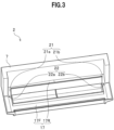
- FIGS. 3 to 6 descriptions will be provided for a configuration of the drain pan 17.
- the example will discuss the configuration in which the drain pan 17 is integrally formed in the housing 7.
- FIG. 3 is a perspective diagram of a drain pan section in the housing 7.
- FIG. 4 is a partially magnified diagram of a front drain pan 17F in the drain pan section.
- FIG. 5 is a graphic diagram showing a relationship between a surface area of the heat exchanger 16 and an amount of drain water produced by the freeze washing.
- FIG. 6 is a schematic diagram illustrating an arrangement structure of a drain pipe 22 in the drain pan section.
- the drain pan 17 includes: a rear drain pan 17R arranged under the rear heat exchanger 16R (see FIG. 2 ); and a front drain pan 17F arranged under the front heat exchanger 16F (see FIG. 2 ).
- communicating passages 21a, 21b are provided in two sides of the rear drain pan 17R.
- drain pipes 22a, 22b are provided in two sides of the front drain pan 17F.
- the communicating passages 21a, 21b will be hereinafter generically referred to as a "communicating passage 21.”
- the drain pipes 22a, 22b will be hereinafter generically referred to as a "drain pipe 22.”
- the rear drain pan 17R receives water which drops from the rear heat exchanger 16R (see FIG. 2 ).
- a bottom surface of the rear drain pan 17R inclines downward from its part farthest from the communicating passage 21 toward its part nearest to the communicating passage 21.
- the bottom surface of the rear drain pan 17R has a shape in which: the bottom surface is highest around its substantially central portion in the left-right direction, and is lower in its left and right end portions than its substantially central portion.
- a bottom surface of the communicating passage 21 inclines downward from the rear drain pan 17R toward the front drain pan 17F.
- water dropping from the rear heat exchanger 16R flows out from the communicating passage 21 to the front drain pan 17F.
- the front drain pan 17F communicates with the drain pipe 22.
- the drain pipe 22 is formed as a circular pipe which is an integral part of the housing 7.
- the drain pipe 22 has a structure in which its inlet 23 is opened toward the inside of the front drain pan 17F.
- the front drain pan 17F receives water dropping from the front heat exchanger 16F (see FIG. 2 ). Furthermore, water dropping from the rear heat exchanger 16R (see FIG. 2 ) flows into the front drain pan 17F from the rear drain pan 17R. Water dropping from the front heat exchanger 16F (see FIG. 2 ) and water dropping from the rear heat exchanger 16R (see FIG. 2 ) are discharged to the outside of the indoor unit 2 via the drain pipe 22. The water dropping from the front heat exchanger 16F (see FIG. 2 ) and the water dropping from the rear heat exchanger 16R (see FIG. 2 ) will be hereinafter generically referred to as "drain water.”
- the freezing operation makes a large amount of frost (or ice) adhere to the rear heat exchanger 16R and the front heat exchanger 16F per unit time, which is larger than an amount of water the normal cooling or dehumidifying operation makes adhere to the rear heat exchanger 16R and the front heat exchanger 16F per unit time.
- the frost (ice) having adhered to the rear heat exchanger 16R and the front heat exchanger 16F melts all at once during the melting operation.
- the large amount of drain water which is larger than the amount of water produced per unit time during the normal cooling or dehumidifying operation, is produced per unit time during the freezing operation.
- Such a large amount of drain water drops into the rear drain pan 17R and the front drain pan 17F all at once.
- the drain water would spill out of the front drain pan 17F or the rear drain pan 17R before the drain water is discharged to the outside of the indoor unit 2 via the drain pipes 22a, 22b. The drain water would thus leak to the outside of the indoor unit 2.
- the air conditioner 1 be designed not to allow the large amount of drain water produced during the melting operation to leak to the outside of the indoor unit 2. It is accordingly desirable that the drain pan 17 have a volume large enough not to allow the large amount of drain water produced during the melting operation to spill out of the drain pan 17.
- the indoor unit 2 is configured such that the volume of the whole drain pan 17 including the rear drain pan 17R and the front drain pan 17F is equal to or greater than a total adhesion amount of frost or ice to adhere to the heat exchanger 16 during the freezing operation.
- the indoor unit 2 is configured such that based on the total adhesion amount of frost or ice to adhere to the heat exchanger 16 during the freezing operation, the volume of the drain pan 17 is equal to or greater than (the total adhesion amount of frost or ice - an amount of drainage through the drain pipe 22 per unit time ⁇ a smaller one of the amount of time required for all the frost or ice to melt and the amount of time required for all the frost or ice to drop into the drain pan 17). This point will be discussed in detail later.
- FIG. 5 illustrates a relationship between the surface area of the whole heat exchanger 16 including the rear heat exchanger 16R and the front heat exchanger 16F, and the amount of drain water produced during the freeze washing (a total adhesion amount of frost of ice).
- FIG. 5 shows experimental results which were measured when the air conditioner 1 performed the freeze washing under conditions: an indoor temperature of 27 °C and an indoor humidity of 35%.
- 34.2(ml) 34.2 ⁇ 10 -6 (m 3 ) of drain water was produced in a case that the surface area of the whole heat exchanger 16 including the rear heat exchanger 16R and the front hear exchanger 16F was 15 (m 2 ).
- the coefficient 2.28 has a length dimension (in this case, m (meter))
- the dimension of w represents the volume (m 3 ).
- the amount of drain water produced after the melting of frost (ice) is smaller than that in the experiment of FIG. 5 even if the surface area x of the heat exchanger 16 and a freezing time are equal to those in the experiment of FIG. 5 .
- the amount of drain water produced after the melting of frost (ice) can be controlled by controlling the freezing time.
- the volume y 0 (m 3 ) of the drain pan 17, therefore, may be equal to or greater than 2.28 (m) ⁇ 10 -6 ⁇ x(m 2 ).
- the value y 0 (m 3 ) represents the volume of the drain pan 17 which is applied in a case where the process of discharging the drain water from the front drain pan 17F to the outside of the indoor unit 2 via the drain pipe 22 is not taken into consideration.
- the indoor unit 2 performs the process of discharging the drain water from the front drain pan 17F to the outside of the indoor unit 2 via the drain pipe 22 in parallel with the process of melting frost (ice).
- the indoor unit 2 allows the volume of the drain pan 17 to be set at a value y 1 (m 3 ) obtained by subtracting a drainage amount (for example, z ⁇ 10 -6 (m 3 )) of drain water to be discharged through the drainage process from the above value y 0 (m 3 ).
- the volume y 1 (m 3 ) of the drain pan 17 may be equal to or greater than (2.28x-z) ⁇ 10 -6 (m 3 ) .
- the indoor unit 2 can prevent the drain water produced during the freeze washing from leaking to the outside of the indoor unit 2 in the case where the volume y 1 (m 3 ) of the drain pan 17 to be calculated with the drain water discharging process taken into consideration is equal to or greater than (the total adhesion amount (m 3 ) of frost or ice - the amount (m 3 /s) of drainage through the drain pipe 22 per unit time ⁇ the smaller one (s) of the amount of time required for all the frost or ice.
- whether to use the value y 0 (m 3 ) or the value y 1 (m 3 ) as the volume of the drain pan 17 may be chosen depending on the operation. In a case where the value y 0 (m 3 ) is used as the volume of the drain pan 17, the volume of the drain pan 17 is larger than otherwise, and the size of the indoor unit 2 is accordingly larger than otherwise. In exchange for this, however, a larger margin can be set for the spill of the drain water out of the drain pan 17. On the other hand, in a case where the value y 1 (m 3 ) is used as the volume of the drain pan 17, the volume of the drain pan 17 can be made smaller, and the size of the indoor unit 2 can be accordingly reduced.
- the indoor unit 2 not only include the drain pan 17 which is provided with a volume large enough not to allow the large amount of drain water produced during the melting operation to spill out of the drain pan 17, but also have a structure which facilitates the discharging of all the drain water to the outside of the indoor unit 2 through the drain pipe 22 without spilling the drain water out of the front drain pan 17F.
- all the drain water means a total of the drain water dropping from the rear heat exchanger 16R and the drain water dropping from the front heat exchanger 16F.
- the indoor unit 2 is configured such that an inner diameter R (see FIG. 6 ) of the drain pipe 22 and a depth h (see FIG. 6 ) of the front drain pan 17F satisfy a relationship expressed with Equation (9) given below. This point will be discussed in detain later.
- a flow rate of the drain water flowing in the drain pipe 22 per unit time is a product of a cross-sectional area of the inside of the drain pipe 22 made of a circular pipe and an outflow speed of the drain water.
- Torricelli's law is a law on an outflow speed of a liquid which flows out of a container through a relatively small hole made in a side surface of the container.
- the depth "h" of the front drain pan 17F is a value representing the distance from the upper limit surface of the front drain pan 17F which does not allow the drain water to spill out of the front drain pan 17F to a bottom surface BS1 of the front drain pan 17F.
- the flow rate "Q" (m 3 /s) of the drain water flowing in the drain pipe 22 per unit time is a flow rate at which the amount "w" (m 3 ) of drain water (the total adhesion amount “w” (m 3 ) of frost or ice) produced during the melting operation per hour (3600 seconds) flows in the drain pipe 22.
- the amount “w” of drain water corresponds to the volume y 0 (m 3 ) required for the drain pan 17.
- the drain pipe 22 can easily discharge all the drain water to the outside of the indoor unit 2 through the drain pipe 22 without spilling the drain water out of the front drain pan 17F.
- the drain pipe 22 can easily discharge all the drain water to the outside of the indoor unit 2 through the drain pipe 22 without spilling the drain water out of the front drain pan 17F.
- the inner diameter R of the drain pipe 22 preferably may be equal to or greater than 11 (mm), for example.
- the indoor unit 2 is configured such that the inner diameter R of the drain pipe 22 and the depth h of the front drain pan 17F satisfy the relationship expressed with Equation (9).
- the indoor unit 2 like this can discharge the drain water to the outside of the indoor unit 2 before the drain water spills out of the front drain pan 17F. Furthermore, the indoor unit 2 can excellently discharge the large amount of drain water produced during the freeze washing without uselessly increasing the size of the housing 7.
- the drain pipe 22 may be arranged such that a center axis C22 of the drain pipe 22 inclines downward from the inlet 23 to an outlet 24 of the drain pipe 22.
- the indoor unit 2 can smoothly discharge the drain water, which collects in the front drain pan 17F, to the outside of the indoor unit 2.
- the indoor unit 2 makes it easy for the drain water and the dust, which enters the inside of the drain pipe 22, to drop due to their own weights. Even if, therefore, the drain water and the dust in the form of sludge flow into the drain pipe 22, the indoor unit 2 can excellently send out the drain water and the dust to the outside of the indoor unit 2.
- the indoor unit 2 like this can keep the inside of the drain pipe 22 in a condition suitable to discharge the drain water.
- the indoor unit 2 further can inhibit the drain water and the dust from accumulating around the inlet 23 of the drain pipe 22.
- the indoor unit 2 accordingly can improve the efficiency of discharging the drain water which collects in the front drain pan 17F.
- FIG. 7 is a schematic diagram illustrating another arrangement structure of the drain pipe 22.
- the front drain pan 17F has a structure in which in the vicinity of the inlet 23 of the drain pipe 22, a bottom surface BS2 of the front drain pan 17F inclines downward from a side farthest from the inlet 23 of the drain pipe 22 toward a side nearest to the inlet 23 of the drain pipe 22.
- the front drain pan 17F has a shape in which in the vicinity of the outlet of the flow passage, a recessed part is formed in the bottom surface of the front drain pan 17F.
- an inclination angle ⁇ 22 of the center axis C22 of the drain pipe 22 is equal to or greater than an inclination angle ⁇ 17 of the bottom surface BS1 of the front drain pan 17F in the vicinity of the inlet 23 of the drain pipe 22.
- the indoor unit 2 like this facilitates the flow of the drain water including the dust, which collects in the front drain pan 17F, toward the drain pipe 22 due to the drain water's own weight.
- the indoor unit 2 therefore, can discharge the drain water, which collects in the front drain pan 17F, more smoothly that in the case where the indoor unit 2 has the configuration illustrated in FIG. 6 .
- the indoor unit 2 accordingly can improve the efficiency of discharging the drain water which collects in the front drain pan 17F.
- FIG. 8 is a schematic diagram illustrating an inlet structure of the drain pipe 22.
- FIG. 9 is a schematic diagram illustrating another inlet structure of the drain pipe 22.
- the inlet 23 of the drain pipe 22 has a shape in which a lower half circumference of the inlet 23 of the drain pipe 22 extend toward the front of the inlet 23 of the drain pipe 22.
- the indoor unit 2 is configured such that an opening area S23 of the inlet 23 of the drain pipe 22 is larger than a cross-sectional area S22M of the drain pipe 22 in the vicinity of the center of the drain pipe 22.
- an inlet 123 of the drain pipe 22 is formed in the shape of an ellipse facing upward.
- the indoor unit 2 is configured such that an opening area S123 of the inlet 123 of the drain pipe 22 is larger than the cross-sectional area S22M of the drain pipe 22 in the vicinity of the center of the drain pipe 22.
- the drain pipe 22 can efficiently take the drain water, which collects in the front drain pipe 17F, into the drain pipe 22, and discharge it to the outside.
- the indoor unit 2 can efficiently take the drain water including the dust into the drain pipe 22. Even if, therefore, in the vicinity of the inlet 23 of the drain pipe 22, the drain water and the dust mix into sludge and become hard to discharge, the indoor unit 2 can excellently take the drain and the dust into the drain pipe 22, and make them go out to the outside of the indoor unit 2.
- the indoor unit 2 can inhibit the drain water and the dust from accumulating around the inlet 23 of the drain pipe 22.
- the indoor unit 2 accordingly can improve the efficiency of discharging the drain water which collects in the front drain pan 17F.
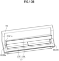
- FIGS. 10A to 10C are schematic diagrams illustrating modifications of the drain pan section of the housing 7.
- the housing 7A in an example illustrated FIG. 10A is different from the housing 7 illustrated in FIG. 3 in that: the rear drain pan 17R has a shape extended in the left-right direction; and the communicating passages 21a, 21b are arranged in places on a front side of the rear drain pan 17R.
- the communicating passages 21a, 21b are arranged in locations near both left and right sides of the rear drain pan 17R.
- the bottom surfaces of the communicating passages 21a, 21b are formed inclining downward from the rear drain pan 17R toward the front drain pan 17F.
- the housing 7B in an example illustrated FIG. 10B is different from the housing 7 illustrated in FIG. 3 in that: the communicating passage 21 is arranged only in a location on either of the left and right sides of the rear drain pan 17R. Furthermore, the bottom surface of the rear drain pan 17R is formed inclining downward from a side farthest from the communicating passage 21 toward a side nearest to the communicating passage 21.
- the housing 7C in an example illustrated FIG. 10C is different from the housing 7B illustrated in FIG. 10B in that: the rear drain pan 17R has a shape extended in the left-right direction; and the communicating part 21 is arranged in a location on a front side of the rear drain pan 17R.
- the communicating passage 21 may be arranged in locations near both the left and right sides of the rear drain pan 17R, in a location of either the left or right side of the rear drain pan 17R, or in a location near either the left or right side of the rear drain pan 17R, instead of being arranged on the two sides of the front drain pan 17F and the rear drain pan 17R.
- the communicating passage 21 thus can make the front drain pan 17F and the rear drain pan 17R communicate with each other.
- the bottom surface of the rear drain pan 17R is formed such that the bottom surface thereof is slightly lower on the sides nearest to the communicating passages 21a, 21b than on the sides farthest from the communicating passages 21a, 21b.
- the housings 7A, 7B, 7C like this illustrated in FIGS. 10A to 10C can increase freedom in the arrangement structure of the communicating passage 21, and can improve the efficiency of discharging the drain water which drops from the rear heat exchanger 16R into the rear drain pan 17R.
- the drain pan 17 has the volume large enough not to allow the large amount of drain water produced during the melting operation to spill out of the drain pan 17.
- the indoor unit 2 therefore, can prevent the drain water from leaking to the outside of the indoor unit 2 during the freeze washing.
- the communicating passage 21 may be configured such that: the communicating passage 21 is arranged in the locations of both the left and right sides of the rear drain pan 17R, or in the locations near both the left and right sides of the rear drain pan 17R; and the bottom surface of the communicating passage 21 inclines downward from the rear drain pan 17R toward the front drain pan 17F (see FIG. 3 or FIG. 10A ).
- the communicating passage 21 may be configured such that: the communicating passage 21 is arranged in the location of either the left or right side of the rear drain pan 17R, or in the location near either the left or right side of the rear drain pan 17R: and the bottom surface of the communicating passage 21 inclines downward from the rear drain pan 17R toward the front drain pan 17F (see FIG. 10B or FIG. 10C ).
- the bottom surface of the rear drain pan 17R may be configured to incline downward from the side farthest from the communicating passage 21 toward the side nearest to the communicating passage 21.
- the indoor unit 2 like this can increase the freedom in the arrangement structure of the communicating passage 21, and can improve the efficiency of discharging the drain water which drops from the rear heat exchanger 16R into the rear drain pan 17R.
- the inner diameter R of the drain pipe 22 and the depth h (m) of the front drain pan 17F may satisfy a relationship expressed with R h 4 > 2.8 ⁇ 10 ⁇ 2 ⁇ y 0 ⁇ g _ where g is the gravitational acceleration (m/s 2 ), and y o is the volume (m 3 ) of the whole drain pan 17 including the rear drain pan 17R and the front drain pan 17F.
- the indoor unit 2 like this can discharge the drain water to the outside of the indoor unit 2 before the drain water spills out of the front drain pan 17F. Furthermore, the indoor unit 2 can excellently discharge the large amount of drain water produced during the freeze washing without uselessly increasing the size of the housing 7.
- the bottom surface of the front drain pan 17F inclines downward from the side farthest from the inlet 23 of the drain pipe 22 toward the side nearest to the inlet 23 of the drain pipe 22 (see FIG. 7 ).
- the indoor unit 2 like this can excellently send out the drain water and the dust to the outside of the indoor unit, even if in the vicinity of the inlet 23 of the drain pipe 22, the drain water and the dust mix into sludge, as well as the drain water and the dust in the form of sludge flow into the drain pipe 22 in the form of sludge.
- the indoor unit 2 like this can keep the inside of the drain pipe 22 in the condition suitable to discharge the drain water.
- the indoor unit 2 further can inhibit the drain water and the dust from accumulating around the inlet 23 of the drain pipe 22.
- the indoor unit 2 accordingly can improve the efficiency of discharging the drain water which collects in the front drain pan 17F.
- the drain pipe 22 is arranged such that the center axis C22 inclines downward from the inlet 23 toward the outlet 24. Furthermore, the inclination angle ⁇ 22 of the center axis C22 of the drain pipe 22 is equal to or greater than the inclination angle ⁇ 17 of the bottom surface BS2 of the front drain pan 17F in the vicinity of the inlet 23 of the drain pipe 22 (see FIG. 7 ).
- the indoor unit 2 makes it easy for the drain water including the dust, which collects in the front drain pan 17F, to flow toward the drain pipe 22 due to the weight of the drain water's own.
- the indoor unit 2 therefore, can smoothly discharge the drain water which collects in the front drain pan 17F.
- the indoor unit 2 accordingly can improve the efficiency of discharging the drain water which collects in the front drain pan 17F.
- the indoor unit 2 may be configured such that the opening surface S23 of the inlet 23 (the opening surface S123 of the inlet 123) of the drain pipe 22 is greater than the cross-sectional area S23M of the drain pipe 22 in the vicinity of the center of the drain pipe 22 (see FIGS. 8 and 9 ) .
- the indoor unit 2 like this can efficiently take the drain water including the dust, which collects in the front drain pan 17F, into the drain pipe 22, and can discharge the drain water including the dust to the outside of the indoor unit 2 through the drain pipe 22.
- the indoor unit 2 can efficiently take the drain water including the dust into the drain pipe 22.
- the indoor unit 2 can excellently take the drain and the dust into the drain pipe 22, and send the drain water and the dust out to the outside of the indoor unit 2 through the drain pipe 22.
- the indoor unit 2 can inhibit the drain water and the dust from accumulating around the inlet 23 of the drain pipe 22.
- the indoor unit 2 accordingly can improve the efficiency of discharging the drain water which collects in the front drain pan 17F.
- the indoor unit 2 for the air conditioner 1 is capable of preventing the water from leaking to the outside of the indoor unit 2 during the freeze washing.
- the first embodiment of the invention provides an indoor unit 2A according to claim 1, with the following points taken into consideration.
- FIG. 11 is a perspective diagram of a drain pan section in a housing 107 to be used for the indoor unit 2A.
- FIG. 12 is a partially-magnified diagram of the front drain pan 17F in the drain pan section.
- FIG. 12 is a magnified diagram illustrating the configuration of an A section and its vicinity in FIG. 11 .
- FIG. 13 is a perspective diagram of the heat insulating material (foamed resin material) 111 to be used in the first embodiment.
- FIGS. 14 and 15 are partially-magnified diagrams of a drainage part 120 in the front drain pan 17F.
- FIG. 11 is a perspective diagram of a drain pan section in a housing 107 to be used for the indoor unit 2A.
- FIG. 12 is a partially-magnified diagram of the front drain pan 17F in the drain pan section.
- FIG. 12 is a magnified diagram illustrating the configuration of an A section and its vicinity in FIG. 11 .
- FIG. 13 is a perspective diagram of the heat insulating material
- FIG. 14 illustrates a configuration of the drainage part 120 taken along the B-B line in the FIG. 12 .
- FIG. 15 illustrates a configuration of the drainage part 120 taken along the C-C line in the FIG. 12 , but near the inlet 23 of the drain pipe 22.
- FIG. 16 is a schematic diagram illustrating an arrangement relationship between the front heat exchanger 16F and the front drain pan 17F.
- the following points make the indoor unit 2A according to the first embodiment different from the indoor unit 2 (see FIG. 2 ) according to the example.
- the heat insulating material 111 (see FIGS. 11 and 12 ), the heat insulating material 161 (see FIG. 11 ) and the heat insulating material 211 (see FIG. 15 ) are members which are attached to the housing 107 of the indoor unit 2A to inhibit moisture in the air from condensing on various portions of the drain pan 17 due to cold drain water which flows into the drain pan 17 during the freeze washing.
- the indoor unit 2A can inhibit moisture in the air from condensing into condensation water to adhere to the drain pan 17, using the heat insulating materials 111, 161, 211 which are arranged on the respective portions of the drain pan 17.
- These heat insulating materials 111, 161, 211 are made of foamed resin material with low hygroscopicity, such as foamed styrol or foamed urethane.
- the heat insulating materials 111, 161 in which their respective flow passages in which drain water flows are formed are made of material with low hygroscopicity, and the surfaces of the heat insulating materials 111, 161 are water-repellent. Since the heat insulating materials 111, 161 like this absorb no water, they can inhibit the growth of molds. Furthermore, the heat insulating materials 111, 161 can make it easy to evaporate drain water flowing into the respective flow passage sections. The heat insulating materials 111, 161 can accordingly contribute to decreasing the size of the drain pan 17.
- mirror surface processing preferably may be applied to the flow passage sections in the heat insulating materials 111, 161 in order to facilitate the flow of the drain water.
- FIG. 13 illustrates an example of the heat insulating material 111.
- the heat insulating material 111 has a structure which enables the heat insulating material 111 to be attached to the drainage part 120 in the inside of the front drain pan 17F which extends in the front-rear direction of the front drain pan 17F.
- the projecting part 112 is formed on an upper surface of the heat insulating material 111.
- the projecting part 112 is formed extending in a direction in which the drain water flows (a direction in which the flow passage extends).
- the projecting part 112 functions as the uneven part 130 for decreasing the surface tension (boding force) of the drain water.
- the indoor unit 2A decreases the surface tension (boding force) of the drain water by use of the projecting part 112 on the heat insulating material 111, and can facilitate the flow of the drain water by allowing droplets of the drain water to flow as they are without having to wait until the droplets grow into drops through bonding. Thereby, the indoor unit 2A facilitates the flow of dust together with the drain water, and decreases an amount of dust which remains inside the drain pan 17.
- the heat insulating material 161 (see FIG. 11 ) has the same shape as the heat insulating material 111.
- the heat insulating material 161 has a structure which enables the heat insulating material 161 to be attached to the inside of the rear drain pan 17R.
- the projecting part 162 is formed extending in the direction in which the drain water flows (the direction in which the flow passage extends).
- the heat insulating material 211 (see FIG. 15 ) has a structure which enables the heat insulating material 211 to be attached to a space located near the inlet 23 of the drain pipe 22, and formed under the drainage part 120 in the front drain pan 17F.
- the projecting parts 122 are formed on the drainage part 120 in the front drain pan 17F (see FIGS. 11 and 12 ). Each projecting part 122 is formed extending in the direction in which the drain water flows (the direction in which the flow passage extends). In this embodiment of the invention, the upper surface of the projecting part 122 is formed in the shape of a substantially flat surface (see FIG. 14 ). Like the projecting part 112, the projecting parts 122 function as the uneven part 130 for decreasing the surface tension (boding force) of the drain water.
- the projecting parts 122 are formed on the drainage part 120 except for in a place immediately before the inlet 23 of the drain pipe 22 (see FIG. 12 ). Thereby, the indoor unit 2A inhibits accumulation of dust around the inlet 23 of the drain pipe 22.
- the projecting parts 122 have a configuration in which the projecting parts 122 are formed directly on the housing 107 which includes the front drain pan 17F.
- the indoor unit 2A may be designed such that: the projecting parts 122 are beforehand formed on a member (not illustrated) separate from the housing 107; and the projecting parts 122 are arranged on the drainage part 120 by attaching the separate member to the drainage part 120.
- a bottom surface of the drainage part 120 in the front drain pan 17F has a shape in which the bottom surface inclines downward toward the inlet 23 of the drain pipe 22 ( FIG. 12 ).
- the drainage part 120 in the front drain pan 17F has a shape in which a recessed portion is formed in the bottom surface near the outlet of the flow passage.
- the communicating passage 21 is provided with the projecting parts 172 (see FIG. 11 ).
- the projecting parts 172 are formed extending in the direction in which the drain water flows (the direction in which the flow passage extends).
- the projecting parts 172 have a configuration in which the projecting parts 172 are formed directly on the housing 107 which includes the front drain pan 17F.
- the heat exchanger 16 in the illustrated example, the front heat exchange 16F
- the drain pan 17 in the illustrated example, the front drain pan 17F
- the indoor unit 2A has a configuration in which the heat exchanger 16 (in the illustrated example, the front heat exchange 16F) and the drain pan 17 (in the illustrated example, the front drain pan 17F) are arranged in close contact with each other, that is to say, a configuration in which no gap is formed between the heat exchanger 16 and the drain pan 17.
- the indoor unit 2A like this can inhibit a decrease in the heat exchanging efficiency, and the occurrence of water droppings (leakage of water to the outside of the indoor unit 2A) which would occur if a gap were formed between the heat exchanger 16 and the drain pan 17.
- the indoor unit 2A can facilitate the movement of condensation water adhering to the fins 20 of the heat exchanger 16 from the fins 20 of the heat exchanger 16 to the drain pan 17. Thereby, the indoor unit 2A can improve the efficiency of washing down the dust which adheres to the heat exchanger 16.
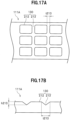
- FIG. 17 is a schematic diagram of a heat insulating material (foamed resin material) 111A according to a modification.
- FIG. 17A illustrates a shape of the heat insulating material 111A which is viewed from above.
- FIG. 17B illustrates a cross-sectional shape of the heat insulating material 111A.
- FIG. 18 is a schematic diagram of a heat insulating material (foamed resin material) 111B according to another modification, and illustrates a shape of the heat insulating material 111B which is viewed from above.
- the heat insulating material 111A has a configuration in which: multiple substantially rectangular projecting parts 212 are arranged at equal intervals in the vertical and horizontal directions; and recessed parts 213 are formed between the projecting parts 212.
- each recessed part 213 is substantially shaped like a triangle which becomes wider upward.
- the recessed parts 213 are formed with a depth h213, with a width t213, and at equal intervals.
- the heat insulating material 111A like this decreases the surface tension (boding force) of the drain water by use of the projecting parts 212, and can facilitate the flow of the drain water by allowing droplets of the drain water to flow as they are without having to wait until the droplets grow into drops through bonding.
- the indoor unit 2A facilitates the flow of the dust together with the drain water, and can decrease an amount of dust which remains inside the drain pan 17.
- the heat insulating material 111A has a larger surface area than the heat insulating material 111 (see FIG. 13 ).
- the heat insulating material 111A makes it easier for drain water flowing into the flow passage section to evaporate than the heat insulating material 111 (see FIG. 13 ).
- the heat insulating material 111B in an example not part of the invention illustrated in FIG. 18 is different from the heat insulating material 111A (see FIG. 18 ) in that the heat insulating material 111B has a configuration in which the projecting parts 212 are staggered one after another.
- the heat insulating material 111B decreases the surface tension (boding force) of the drain water by use of the projecting parts 212, and can facilitate the flow of the drain water.
- the heat insulating material 111B has a larger surface area than the heat insulating material 111 (see FIG. 13 ), since the projecting parts 212 are formed in the flow passage section.
- the heat insulating material 111B makes it easier for drain water flowing into the flow passage section to evaporate than the heat insulating material 111 (see FIG. 13 ) .
- FIG. 19 is a schematic diagram of the drainage part 120 in the front drain pan 17F according to another modification.
- each projecting part 122A is substantially shaped like a triangle which becomes narrower upward.
- Each projecting part 122A is formed extending in the direction in which the drain water flows (the direction in which the flow passage extends).
- Each projecting part 122A is formed with a depth h122A, and with a width t122A.
- the drainage part 120 like this decreases the surface tension (bonding force) of the drain water by use of the projecting parts 122A, and can facilitate the flow of the drain water.
- the indoor unit 2A according to the first embodiment of the invention is capable of preventing the water from leaking to the outside of the indoor unit 2A during the freeze washing, like the indoor unit 2 according to the example.
- the indoor unit 2A can improve the drainage efficiency since the indoor unit 2A can facilitate the flow of the drain water. Moreover, the indoor unit 2A can inhibit moisture in the air from condensing to adhere to the drain pan 17.
Landscapes
- Engineering & Computer Science (AREA)
- Chemical & Material Sciences (AREA)
- Combustion & Propulsion (AREA)
- Mechanical Engineering (AREA)
- General Engineering & Computer Science (AREA)
- Physics & Mathematics (AREA)
- Thermal Sciences (AREA)
- Devices For Blowing Cold Air, Devices For Blowing Warm Air, And Means For Preventing Water Condensation In Air Conditioning Units (AREA)
- Air Filters, Heat-Exchange Apparatuses, And Housings Of Air-Conditioning Units (AREA)
- Air Conditioning Control Device (AREA)
Description
- The present invention relates to an indoor unit for an air conditioner according to the appended claims.
- An indoor unit for an air conditioner conditions indoor air by: suctioning the indoor air into the indoor unit; applying a selected one of heating, cooling and dehumidifying processes to the suctioned indoor air by passing the suctioned indoor air through a heat exchanger to obtain the conditioned air; and blowing out the obtained conditioned air into the building.
- In the indoor unit for the air conditioner, a filter is arranged closing a clearance between an air suction port for suctioning the indoor air and the heat exchanger in order to prevent dust included in the indoor air from entering the inside of the indoor unit, and the filter collects most of the dust. Fine dust smaller than the mesh size of the filter still passes through the mesh of the filter, and enters the inside of the indoor unit.
- Inside the indoor unit, static electricity is produced around the heat exchanger by friction which occurs when the suctioned indoor air hits the heat exchanger. In addition, the fine dust having entered the inside of the indoor unit contains oil in many cases. The fine dust having entered the inside of the indoor unit adheres to the heat exchanger due to the static electricity and the oil.
- The dust adhering to the heat exchanger contains components which are nutrients for bacteria (including molds). Meanwhile, for example, each time the air conditioner performs a cooling or dehumidifying operation in the summer, moisture in the air condenses on fins of the heat exchanger, and the ambient atmosphere around the heat exchanger becomes highly humid. Continuous adhering of the dust to the heat exchanger, therefore, grows the bacteria, and is likely to generate foul smell. In view of this, it is desirable that the air conditioner remove the dust adhering to the heat exchanger to keep the heat exchanger clean throughout the year.
- With this taken into consideration, for example,
Patent Literature 1 has proposed an air conditioner which performs a heating operation and thereafter a cooling or dehumidifying operation to make water adhere to the surfaces of the fins of the heat exchanger, and washes down the dust including the oil, which adheres to the surfaces of the fins, using the adhering water. The air conditioner described inPatent Literature 1, however, requires an anti-dirt treatment to be applied to the surfaces of the fins in order to wash down the dust using the water adhering to the surfaces of the fins. - Against this background, a scheme has been considered, for example, in which: frost or ice is made to adhere to the surfaces of the fins by an operation of decreasing the temperature of the heat exchanger; thereafter, the frost or ice is melted by an operation of raising the temperature of the heat exchanger; and the dust adhering to the heat exchanger is washed down using momentum with which the melted water flows down. The process of washing the heat exchanger in this way will be hereinafter referred to as "freeze washing." This freeze washing can make a large amount of frost (including ice) adhere to the surfaces of the fins per unit time, which is larger than an amount of water a normal cooling or dehumidifying operation makes adhere to the surfaces of the fins per unit time. This freeze washing, therefore, can wash down the dust adhering to the heat exchanger without applying the anti-dirt treatment to the surfaces of the fins.
Patent Literature 2 describes an air conditioner which includes a housing including a front panel and a rear panel. The heat exchanger is disposed within the housing and includes a lower drain tray which is positioned beneath the front portion of the heat exchanger and an upper drain tray which is positioned beneath the rear portion of the heat exchanger. The upper drain tray is of integrally molded construction with a rear panel so that no gaps are present therebetween. -
- Patent Literature 1:
Japanese Patent Application Publication No. 2008-138913 - Patent Literature 2:
US 6062032 A - The freeze washing, however, produces a large amount of water (drain water) per unit time, which is larger than an amount of water the normal cooling or dehumidifying operation does. It is desired that the air condition not leak the large amount of water (drain water) to the outside of the indoor unit.
- The present invention has been made to solve the above problem. A main object of the present invention is to provide an indoor unit for an air conditioner which leaks no water to the outside of the indoor unit during the freeze washing.
- The above problem is solved by the appended claims.
- According to the present invention, it is possible to prevent water from leaking to the outside during the freeze washing.
-
-
FIG. 1 is a configuration diagram of an air conditioner according to an example not part of the invention but suitable for understanding certain details of the invention. -
FIG. 2 is a cross-sectional diagram of an indoor unit for the air conditioner according to the example. -
FIG. 3 is a perspective diagram of a drain pan section in a housing used for the indoor unit according to the example. -
FIG. 4 is a partially magnified diagram of a front drain pan in the drain pan section. -
FIG. 5 is a graphic diagram illustrating a relationship between a surface area of a heat exchanger and an amount of drain water produced by freeze washing. -
FIG. 6 is a schematic diagram illustrating an arrangement structure of a drain pipe in the drain pan section. -
FIG. 7 is a schematic diagram illustrating another arrangement structure of the drain pipe in the drain pan section. -
FIG. 8 is a schematic diagram illustrating a structure of an inlet of the drain pipe in the drain pan section. -
FIG. 9 is a schematic diagram illustrating another structure of the inlet of the drain pipe in the drain pan section. -
FIG. 10A is a schematic diagram (1) of a drain pan section of a housing according to a modification. -
FIG. 10B is a schematic diagram (2) of a drain pan section of a housing according to a modification. -
FIG. 10C is a schematic diagram (3) of a drain pan section of a housing according to a modification. -
FIG. 11 is a perspective diagram of a drain pan section in a housing used in an indoor unit according to a first embodiment of the invention. -
FIG. 12 is a partially magnified diagram of a front drain pan in the drain pan section. -
FIG. 13 is a perspective diagram of a heat insulating material used in the first embodiment. -
FIG. 14 is a partially magnified diagram (1) of a drainage part in a front drain pan. -
FIG. 15 is a partially magnified diagram (2) of the drainage part in the front drain pan. -
FIG. 16 is a schematic diagram illustrating an arrangement relationship between the heat exchanger and the front drain pan. -
FIG. 17 is a schematic diagram (1) of a heat insulating material according to a modification. -
FIG. 18 is a schematic diagram (2) of a heat insulating material according to a modification. -
FIG. 19 is a schematic diagram of a drainage part in a front drain pan according a modification. - Hereinafter, examples not part of the invention and embodiments of the invention will be described in detail with reference to the accompanying drawings. It should be noted that the drawings only schematically show the present invention to an extent that the present invention can be sufficiently understood. The present invention is not limited to illustrated examples and is defined in the claims. The same reference signs are used throughout the drawings to refer to common components and similar components, and duplicated descriptions are omitted.
- Referring to
FIGS. 1 and2 , descriptions will be hereinbelow provided for a configuration of anair conditioner 1 according to the example.FIG. 1 is a configuration diagram of theair conditioner 1 according to the example.FIG. 2 is a cross-sectional diagram of anindoor unit 2 of theair conditioner 1. - As illustrated in
FIG. 1 , theair conditioner 1 includes theindoor unit 2 placed inside a building, an outdoor unit 3 placed outside the building, and aremote controller 12 placed near a user inside the building. - The
indoor unit 2 conditions indoor air by: suctioning the indoor air into theindoor unit 2; applying a selected one of heating, cooling and dehumidifying processes to the suctioned indoor air by passing the suctioned indoor air through a heat exchanger 16 (seeFIG. 2 ); obtaining the conditioned air; and blowing out the obtained conditioned air into the building. Theindoor unit 2 is connected to the outdoor unit 3 through a connectingpipe 5, and circulates a refrigerant between theindoor unit 2 and the outdoor unit 3. The outdoor unit 3 exchanges heat between the air and the circulating refrigerant. - The
indoor unit 2 includes structural bodies such as an air blowing fan 14 (seeFIG. 2 ) and the heat exchanger 16 (seeFIG. 2 ) inside ahousing 7 and adecorative frame 8. Theair blowing fan 14 is a through-flow fan which sends air from anair inlet port 6 to anair outlet port 13. Theheat exchanger 16 is a unit which exchanges heat between the air and the refrigerant. - In an example illustrated in
FIG. 1 , a front surface of thedecorative frame 8 has a shape which: includes an upper portion extending in an up-down direction; and a lower portion whose low side extends slantingly toward a rear. Afront panel 9 is attached to the upper portion of the front surface of thedecorative frame 8. Thefront panel 9 is a member covering the front surface of theindoor unit 2. Furthermore, areceiver 10, adisplay 11, and an up-downwind direction board 18 are mounted in the lower portion of the front surface of thedecorative frame 8. - The
receiver 10 is a device which receives operation signals sent from theremote controller 12. Thereceiver 10 is electrically connected to a controller CL built in theindoor unit 2. The controller CL controls operations and actions of theair conditioner 1 based on the operation signals received from theremote controller 12 via thereceiver 10. - The
display 11 is a device which displays how theair conditioner 1 is operating. - The up-down
wind direction board 18 is a member for defining an up-down direction of the conditioned air which is blown out from theair outlet port 13. The up-downwind direction board 18 has a configuration in which: the up-downwind direction board 18 is pivotally supported near its lower end by the decorative frame 8 (or the housing 7) such that an upper portion of the up-downwind direction board 18 opens and closes in the up-down direction; and the up-downwind direction board 18 is turned by a driving section (not illustrated). Theindoor unit 2 forms theair outlet port 13 by opening the up-downwind direction board 18. - As illustrated in
FIG. 2 , theindoor unit 2 includes, in its inside, afilter 15, adrain pan 17 and a left-rightwind direction board 19 in addition to theair flowing fan 14, theheat exchanger 16 and the up-downwind direction board 18. - The
filter 15 is a member for preventing dust from entering the inside of thehousing 7. - The
drain pan 17 is a member for receiving drops of water (drain water) which condenses on the surfaces offins 20 of theheat exchanger 16. - The left-right
wind direction board 19 is a member for defining a left-right direction of the conditioned air which is blown out from theair outlet port 13. - The
filter 15 is arranged in a way that closes a gap between theair inlet port 6 and theheat exchanger 16. Theair conditioner 1 has a configuration in which: thefilter 15 prevents dust larger than the mesh size of thefilter 15 from entering the inside of thehousing 7; and by freeze washing (described later), theair conditioner 1 washes away dust which passes through the mesh of thefilter 15 because of being smaller than the mesh size of thefilter 15. Theair conditioner 1 preferably has a configuration including a filter cleaning mechanism (not illustrated), and may be capable of automatically cleaning thefilter 15 using the filter cleaning mechanism (more preferably, on a regular basis). - The
air blowing fan 14 is arranged near a substantially central portion of the inside of theindoor unit 2 such that theair blowing fan 14 is capable of: suctioning the air from theair inlet port 6; and blowing out the air from theair outlet port 13. Theheat exchanger 16 is arranged upstream of the air blowing fan 14 (on a side closer to the air inlet port 6), and is formed substantially in the shape of the letter V turned upside down to cover an upstream side of theair blowing fan 14. - The
heat exchanger 16 includes afront heat exchanger 16F and arear heat exchanger 16R. Thefront heat exchanger 16F and therear heat exchanger 16R each include multiple fins (heat exchange plates) 20, andmultiple pipes 40 penetrating through themultiple fins 20. Eachfin 20 is a long thin plate-shaped member for exchanging heat between the refrigerant and the air. Thefin 20 is made from, for example, an aluminum alloy. Eachpipe 40 is a member in which the refrigerant flows. - With the above configuration, using the
filter 15, theindoor unit 2 collects most of the dust from the indoor air suctioned into theindoor unit 2. Some of the dust, however, cannot be collected by thefilter 15. Such dust passes through the mesh of thefilter 15, and enters the inside of theindoor unit 2 to adhere to theheat exchanger 16. If such dust continues to adhere to theheat exchanger 16, there is likelihood that bacteria (including molds) grow and start to smell foul. With this taken into consideration, it is desirable that theair conditioner 1 be configured to remove dust which adheres to theheat exchanger 16. In this example, therefore, theair conditioner 1 performs the following washing process on theheat exchanger 16 by controlling operations. - To put it specifically, to begin with, the
air conditioner 1 performs an action of making frost or ice adhere to the surfaces of thefins 20 of the heat exchanger 16 (hereinafter referred to as a "freezing action") by performing an operation of decreasing the temperature of theheat exchanger 16 to cool theheat exchanger 16 quickly. In this example, an operation for the freezing action is referred to as a "freezing operation." - One may consider that the freezing operation sublimes moisture in the air to make frost (including ice) directly adhere to the surfaces of the
fins 20 of theheat exchanger 16 without passing the moisture through a water droplet phase. There is, however, likelihood that moisture in the air condenses on the surfaces of thefins 20 of theheat exchanger 16, and the condensed moisture freezes thereon to make frost (ice) adhere to the surfaces of thefins 20 of theheat exchanger 16 after passing through a water droplet phase. - It should be noted that during the freezing operation, the
air conditioner 1 does not operate theair blowing fan 14 unlike during the normal cooling operation. This makes it possible for theair conditioner 1 to inhibit the dropping (falling) of water (condensed water) condensed on the surfaces of thefins 20 of theheat exchanger 16, and thereby to make the water (condensed water) stay on the surfaces of thefins 20 for a longer time. Theair conditioner 1 can thus secure a stable amount of frozen water. - After the freezing operation, the
air conditioner 1 performs an action of defrosting (melting) the frost (ice) (hereinafter referred to as a "melting action") by performing an operation of raising the temperature of theheat exchanger 16 to heat theheat exchanger 16 quickly. In this example, an operation for the melting action is referred to as a "melting operation." By the melting operation, theair conditioner 1 turns the frost (ice) back into water. While turning the frost (ice) back into water, theair conditioner 1 washes down fine dust adhering to theheat exchanger 16, using momentum with which the melted (defrosted) water drops down. This makes it possible for theair conditioner 1 to enhance the maintainability of theheat exchanger 16, and accordingly to wash theheat exchanger 16 efficiently. This washing process (the washing process performed by the freezing operation and the melting operation in combination) will be hereinafter referred to as a "freeze washing." - It should be noted that using the
drain pan 17, theair conditioner 1 receives water (drain water) which flows out during the melting operation. A flow passage in which the water (drain water) flows is formed in thedrain pan 17. Mirror surface processing is applied to an inner wall surface of the flow passage in order to facilitate the flow of the water (drain water). A drain pipe is connected to the flow passage. Theair conditioner 1 discharges the water (drain water) flowing out via the drain pipe, to the outside of thehousing 7. - Referring to
FIGS. 3 to 6 , descriptions will be provided for a configuration of thedrain pan 17. The example will discuss the configuration in which thedrain pan 17 is integrally formed in thehousing 7.FIG. 3 is a perspective diagram of a drain pan section in thehousing 7.FIG. 4 is a partially magnified diagram of afront drain pan 17F in the drain pan section.FIG. 5 is a graphic diagram showing a relationship between a surface area of theheat exchanger 16 and an amount of drain water produced by the freeze washing.FIG. 6 is a schematic diagram illustrating an arrangement structure of adrain pipe 22 in the drain pan section. - As illustrated in
FIG. 3 , thedrain pan 17 includes: arear drain pan 17R arranged under therear heat exchanger 16R (seeFIG. 2 ); and afront drain pan 17F arranged under thefront heat exchanger 16F (seeFIG. 2 ). In this example, communicatingpassages rear drain pan 17R. Furthermore,drain pipes front drain pan 17F. The communicatingpassages passage 21." In addition, thedrain pipes drain pipe 22." - The
rear drain pan 17R receives water which drops from therear heat exchanger 16R (seeFIG. 2 ). A bottom surface of therear drain pan 17R inclines downward from its part farthest from the communicatingpassage 21 toward its part nearest to the communicatingpassage 21. In this example, the bottom surface of therear drain pan 17R has a shape in which: the bottom surface is highest around its substantially central portion in the left-right direction, and is lower in its left and right end portions than its substantially central portion. Thus, water dropping from therear heat exchanger 16R (seeFIG. 2 ) flows out from therear drain pan 17R to the communicatingpassage 21. - A bottom surface of the communicating
passage 21 inclines downward from therear drain pan 17R toward thefront drain pan 17F. Thus, water dropping from therear heat exchanger 16R (seeFIG. 2 ) flows out from the communicatingpassage 21 to thefront drain pan 17F. - As illustrated in
FIG. 4 , thefront drain pan 17F communicates with thedrain pipe 22. In this example, thedrain pipe 22 is formed as a circular pipe which is an integral part of thehousing 7. Thedrain pipe 22 has a structure in which itsinlet 23 is opened toward the inside of thefront drain pan 17F. - The
front drain pan 17F receives water dropping from thefront heat exchanger 16F (seeFIG. 2 ). Furthermore, water dropping from therear heat exchanger 16R (seeFIG. 2 ) flows into thefront drain pan 17F from therear drain pan 17R. Water dropping from thefront heat exchanger 16F (seeFIG. 2 ) and water dropping from therear heat exchanger 16R (seeFIG. 2 ) are discharged to the outside of theindoor unit 2 via thedrain pipe 22. The water dropping from thefront heat exchanger 16F (seeFIG. 2 ) and the water dropping from therear heat exchanger 16R (seeFIG. 2 ) will be hereinafter generically referred to as "drain water." - In the
indoor unit 2, the freezing operation makes a large amount of frost (or ice) adhere to therear heat exchanger 16R and thefront heat exchanger 16F per unit time, which is larger than an amount of water the normal cooling or dehumidifying operation makes adhere to therear heat exchanger 16R and thefront heat exchanger 16F per unit time. The frost (ice) having adhered to therear heat exchanger 16R and thefront heat exchanger 16F melts all at once during the melting operation. Thus, the large amount of drain water, which is larger than the amount of water produced per unit time during the normal cooling or dehumidifying operation, is produced per unit time during the freezing operation. Such a large amount of drain water drops into therear drain pan 17R and thefront drain pan 17F all at once. - If the
rear drain pan 17R or thefront drain pan 17F had not had a volume large enough to contain the large amount of drain water produced during the melting operation, the drain water would spill out of thefront drain pan 17F or therear drain pan 17R before the drain water is discharged to the outside of theindoor unit 2 via thedrain pipes indoor unit 2. With this taken into consideration, it is desirable that theair conditioner 1 be designed not to allow the large amount of drain water produced during the melting operation to leak to the outside of theindoor unit 2. It is accordingly desirable that thedrain pan 17 have a volume large enough not to allow the large amount of drain water produced during the melting operation to spill out of thedrain pan 17. - In view of this, in this example, the
indoor unit 2 is configured such that the volume of thewhole drain pan 17 including therear drain pan 17R and thefront drain pan 17F is equal to or greater than a total adhesion amount of frost or ice to adhere to theheat exchanger 16 during the freezing operation. Incidentally, given that drain water is discharged to the outside of theindoor unit 2 via thedrain pipe 22, theindoor unit 2 is configured such that based on the total adhesion amount of frost or ice to adhere to theheat exchanger 16 during the freezing operation, the volume of thedrain pan 17 is equal to or greater than (the total adhesion amount of frost or ice - an amount of drainage through thedrain pipe 22 per unit time × a smaller one of the amount of time required for all the frost or ice to melt and the amount of time required for all the frost or ice to drop into the drain pan 17). This point will be discussed in detail later. - In this respect,
FIG. 5 illustrates a relationship between the surface area of thewhole heat exchanger 16 including therear heat exchanger 16R and thefront heat exchanger 16F, and the amount of drain water produced during the freeze washing (a total adhesion amount of frost of ice).FIG. 5 shows experimental results which were measured when theair conditioner 1 performed the freeze washing under conditions: an indoor temperature of 27 °C and an indoor humidity of 35%. As illustrated inFIG. 5 , in the experiment, for example, 34.2(ml)=34.2×10⁻⁶ (m3) of drain water was produced in a case that the surface area of thewhole heat exchanger 16 including therear heat exchanger 16R and the front hear exchanger 16F was 15 (m2). In other words, the amount w (m3) of drain water produced during the melting operation (the total adhesion amount of frost or ice) and the surface area x (m2) of theheat exchanger 16 has a relationship expressed with
- Meanwhile, in a case where the freeze washing is performed in an environment where the indoor humidity is lower than that in the experiment of
FIG. 5 , the amount of drain water produced after the melting of frost (ice) is smaller than that in the experiment ofFIG. 5 even if the surface area x of theheat exchanger 16 and a freezing time are equal to those in the experiment ofFIG. 5 . In addition, in a case where the freeze washing is performed in an environment where the indoor humidity is higher than that in the experiment ofFIG. 5 , the amount of drain water produced after the melting of frost (ice) can be controlled by controlling the freezing time. Theindoor unit 2, therefore, can prevent the drain water produced during the freeze washing from leaking to the outside of theindoor unit 2 in a case where the volume y0 (m3) of thewhole drain pan 17 including therear drain pan 17R and thefront drain pan 17F is equal to or greater than w (m3), that is to say, (y0=2.28×10⁻⁶×x) (m3). The volume y0 (m3) of thedrain pan 17, therefore, may be equal to or greater than 2.28 (m) ×10-6×x(m2). - It should be noted that the value y0 (m3) represents the volume of the
drain pan 17 which is applied in a case where the process of discharging the drain water from thefront drain pan 17F to the outside of theindoor unit 2 via thedrain pipe 22 is not taken into consideration. In contrast to this, theindoor unit 2 performs the process of discharging the drain water from thefront drain pan 17F to the outside of theindoor unit 2 via thedrain pipe 22 in parallel with the process of melting frost (ice). - In a case where, therefore, the drain water discharging process is taken into consideration, the
indoor unit 2 allows the volume of thedrain pan 17 to be set at a value y1 (m3) obtained by subtracting a drainage amount (for example, z×10-6(m3)) of drain water to be discharged through the drainage process from the above value y0 (m3). In other words, in the case where the drain water discharging process is taken into consideration, theindoor unit 2 can prevent the drain water produced through the freeze washing from leaking to the outside of theindoor unit 2 when the volume y1 (m3) of thewhole drain pan 17 including therear drain pan 17R and thefront drain pan 17F is equal to or greater than (w-z×10-6) (m3), that is to say, (y1=2.28×10⁻⁶×x-z×10-6=(2.28x-Z)×10-6) (m3) . In the case where, therefore, the drain water discharging process is taken into consideration, the volume y1 (m3) of thedrain pan 17 may be equal to or greater than (2.28x-z) ×10-6 (m3) . - In the value (2 .28x-Z) ×10-6, the value 2.28x×10-6 corresponds to the "total adhesion amount (m3) of frost or ice, " while the value Z×10-6 corresponds to the "amount (m3/s) of drainage through the
drain pipe 22 per unit time × the smaller one (s) of the amount of time required for all the frost or ice to melt and the amount of time required for all the frost or ice to drop into thedrain pan 17." In other words, theindoor unit 2 can prevent the drain water produced during the freeze washing from leaking to the outside of theindoor unit 2 in the case where the volume y1 (m3) of thedrain pan 17 to be calculated with the drain water discharging process taken into consideration is equal to or greater than (the total adhesion amount (m3) of frost or ice - the amount (m3/s) of drainage through thedrain pipe 22 per unit time × the smaller one (s) of the amount of time required for all the frost or ice to melt and the amount of time required for all the frost or ice to drop into the drain pan 17) . - It should be noted that whether to use the value y0 (m3) or the value y1 (m3) as the volume of the
drain pan 17 may be chosen depending on the operation. In a case where the value y0 (m3) is used as the volume of thedrain pan 17, the volume of thedrain pan 17 is larger than otherwise, and the size of theindoor unit 2 is accordingly larger than otherwise. In exchange for this, however, a larger margin can be set for the spill of the drain water out of thedrain pan 17. On the other hand, in a case where the value y1 (m3) is used as the volume of thedrain pan 17, the volume of thedrain pan 17 can be made smaller, and the size of theindoor unit 2 can be accordingly reduced. - It is desirable that the
indoor unit 2 not only include thedrain pan 17 which is provided with a volume large enough not to allow the large amount of drain water produced during the melting operation to spill out of thedrain pan 17, but also have a structure which facilitates the discharging of all the drain water to the outside of theindoor unit 2 through thedrain pipe 22 without spilling the drain water out of thefront drain pan 17F. In this respect, "all the drain water" means a total of the drain water dropping from therear heat exchanger 16R and the drain water dropping from thefront heat exchanger 16F. - To this end, in this example, the
indoor unit 2 is configured such that an inner diameter R (seeFIG. 6 ) of thedrain pipe 22 and a depth h (seeFIG. 6 ) of thefront drain pan 17F satisfy a relationship expressed with Equation (9) given below. This point will be discussed in detain later. - In this respect, a flow rate of the drain water flowing in the
drain pipe 22 per unit time is a product of a cross-sectional area of the inside of thedrain pipe 22 made of a circular pipe and an outflow speed of the drain water. The flow rate "Q" (m3/s) of the drain water flowing in thedrain pipe 22 per unit time, therefore, has a relationship expressed with
drain pipe 22 with the inner diameter R (m) (that is to say, R=2r), and v is the outflow speed (m/s) of the drain water flowing in thedrain pipe 22. - Furthermore, based on Torricelli's law, the outflow speed "v" (m/s) of the drain water flowing in the
drain pipe 22 has a relationship expressed with
front drain pan 17F, and g is a gravitational acceleration (m/s2). Incidentally, Torricelli's law is a law on an outflow speed of a liquid which flows out of a container through a relatively small hole made in a side surface of the container. Furthermore, the depth "h" of thefront drain pan 17F is a value representing the distance from the upper limit surface of thefront drain pan 17F which does not allow the drain water to spill out of thefront drain pan 17F to a bottom surface BS1 of thefront drain pan 17F. - By substituting Equation (2) for v in Equation (1),

- In this respect, the flow rate "Q" (m3/s) of the drain water flowing in the
drain pipe 22 per unit time is a flow rate at which the amount "w" (m3) of drain water (the total adhesion amount "w" (m3) of frost or ice) produced during the melting operation per hour (3600 seconds) flows in thedrain pipe 22. In addition, the amount "w" of drain water (the total adhesion amount "w" of frost or ice) corresponds to the volume y0 (m3) required for thedrain pan 17. The flow rate "Q" (m3/s) of the drain water flowing in thedrain pipe 22 per unit time, therefore, has a relationship expressed with
- By substituting Equation (4) for Q in Equation (3),

- From Equation (5),

- Furthermore, from Equation (6),

- Since the inner diameter "R" of the
drain pipe 22 is equal to 2r, from Equation (7),
- When the inner diameter "R" of the
drain pipe 22 is set larger than a value which satisfies the relationship expressed with Equation (8), thedrain pipe 22 can easily discharge all the drain water to the outside of theindoor unit 2 through thedrain pipe 22 without spilling the drain water out of thefront drain pan 17F. When, therefore, the inner diameter R (FIG. 6 ) of thedrain pipe 22 and the depth h (FIG. 6 ) of thefront drain pan 17F are set in a way that satisfies a relationship expressed with
drain pipe 22 can easily discharge all the drain water to the outside of theindoor unit 2 through thedrain pipe 22 without spilling the drain water out of thefront drain pan 17F. - It should be noted that: y0 (m3) represents the volume of the
whole drain pan 17 including therear drain pan 17R and thefront drain pan 17F; and the volume y0 (m3) of thewhole drain pan 17 and the surface area x (m2) of thewhole heat exchanger 16 including therear heat exchanger 16R and thefront heat exchanger 16F has a relationship expressed with
drain pipe 22 preferably may be equal to or greater than 11 (mm), for example. - The
indoor unit 2 is configured such that the inner diameter R of thedrain pipe 22 and the depth h of thefront drain pan 17F satisfy the relationship expressed with Equation (9). Theindoor unit 2 like this can discharge the drain water to the outside of theindoor unit 2 before the drain water spills out of thefront drain pan 17F. Furthermore, theindoor unit 2 can excellently discharge the large amount of drain water produced during the freeze washing without uselessly increasing the size of thehousing 7. - It should be noted that as illustrated in
FIG. 6 , thedrain pipe 22 may be arranged such that a center axis C22 of thedrain pipe 22 inclines downward from theinlet 23 to anoutlet 24 of thedrain pipe 22. Thus, theindoor unit 2 can smoothly discharge the drain water, which collects in thefront drain pan 17F, to the outside of theindoor unit 2. - Furthermore, during the freeze washing, dust having adhered to the
front heat exchanger 16F and therear heat exchanger 16R flows down together with the drain water. In the vicinity of theinlet 23 of thedrain pipe 22, therefore, the drain water and the dust mix together into sludge and easily accumulate. Accordingly, the drain water and the dust in the form of sludge are highly likely to enter the inside of thedrain pipe 22. - Because of the slanting arrangement of the
drain pipe 22, however, theindoor unit 2 makes it easy for the drain water and the dust, which enters the inside of thedrain pipe 22, to drop due to their own weights. Even if, therefore, the drain water and the dust in the form of sludge flow into thedrain pipe 22, theindoor unit 2 can excellently send out the drain water and the dust to the outside of theindoor unit 2. Theindoor unit 2 like this can keep the inside of thedrain pipe 22 in a condition suitable to discharge the drain water. Theindoor unit 2 further can inhibit the drain water and the dust from accumulating around theinlet 23 of thedrain pipe 22. Theindoor unit 2 accordingly can improve the efficiency of discharging the drain water which collects in thefront drain pan 17F. - Meanwhile, the shape of the bottom surface BS1 of the
front drain pan 17F may be changed, for example, as illustrated inFIG. 7. FIG. 7 is a schematic diagram illustrating another arrangement structure of thedrain pipe 22. As illustrated inFIG. 7 , thefront drain pan 17F has a structure in which in the vicinity of theinlet 23 of thedrain pipe 22, a bottom surface BS2 of thefront drain pan 17F inclines downward from a side farthest from theinlet 23 of thedrain pipe 22 toward a side nearest to theinlet 23 of thedrain pipe 22. In other words, thefront drain pan 17F has a shape in which in the vicinity of the outlet of the flow passage, a recessed part is formed in the bottom surface of thefront drain pan 17F. Furthermore, an inclination angle α22 of the center axis C22 of thedrain pipe 22 is equal to or greater than an inclination angle α17 of the bottom surface BS1 of thefront drain pan 17F in the vicinity of theinlet 23 of thedrain pipe 22. Theindoor unit 2 like this facilitates the flow of the drain water including the dust, which collects in thefront drain pan 17F, toward thedrain pipe 22 due to the drain water's own weight. Theindoor unit 2, therefore, can discharge the drain water, which collects in thefront drain pan 17F, more smoothly that in the case where theindoor unit 2 has the configuration illustrated inFIG. 6 . Theindoor unit 2 accordingly can improve the efficiency of discharging the drain water which collects in thefront drain pan 17F. - The shape of the
inlet 23 of thedrain pipe 22 may be changed, for example, as illustrated inFIGS. 8 or9 .FIG. 8 is a schematic diagram illustrating an inlet structure of thedrain pipe 22.FIG. 9 is a schematic diagram illustrating another inlet structure of thedrain pipe 22. - In a case illustrated in
FIG. 8 , theinlet 23 of thedrain pipe 22 has a shape in which a lower half circumference of theinlet 23 of thedrain pipe 22 extend toward the front of theinlet 23 of thedrain pipe 22. Thereby, theindoor unit 2 is configured such that an opening area S23 of theinlet 23 of thedrain pipe 22 is larger than a cross-sectional area S22M of thedrain pipe 22 in the vicinity of the center of thedrain pipe 22. - Meanwhile, in a case illustrated in
FIG. 9 , aninlet 123 of thedrain pipe 22 is formed in the shape of an ellipse facing upward. Thereby, theindoor unit 2 is configured such that an opening area S123 of theinlet 123 of thedrain pipe 22 is larger than the cross-sectional area S22M of thedrain pipe 22 in the vicinity of the center of thedrain pipe 22. - With the configuration illustrated in
FIG. 8 orFIG. 9 , thedrain pipe 22 can efficiently take the drain water, which collects in thefront drain pipe 17F, into thedrain pipe 22, and discharge it to the outside. Thereby, theindoor unit 2 can efficiently take the drain water including the dust into thedrain pipe 22. Even if, therefore, in the vicinity of theinlet 23 of thedrain pipe 22, the drain water and the dust mix into sludge and become hard to discharge, theindoor unit 2 can excellently take the drain and the dust into thedrain pipe 22, and make them go out to the outside of theindoor unit 2. Thus, theindoor unit 2 can inhibit the drain water and the dust from accumulating around theinlet 23 of thedrain pipe 22. Theindoor unit 2 accordingly can improve the efficiency of discharging the drain water which collects in thefront drain pan 17F. - The drain pan section of the
housing 7 may be changed, for example, to those ofhousings FIGS. 10A to 10C. FIGS. 10A to 10C are schematic diagrams illustrating modifications of the drain pan section of thehousing 7. - The
housing 7A in an example illustratedFIG. 10A is different from thehousing 7 illustrated inFIG. 3 in that: therear drain pan 17R has a shape extended in the left-right direction; and the communicatingpassages rear drain pan 17R. In thehousing 7A, specifically, the communicatingpassages rear drain pan 17R. Furthermore, the bottom surfaces of the communicatingpassages rear drain pan 17R toward thefront drain pan 17F. - The
housing 7B in an example illustratedFIG. 10B is different from thehousing 7 illustrated inFIG. 3 in that: the communicatingpassage 21 is arranged only in a location on either of the left and right sides of therear drain pan 17R. Furthermore, the bottom surface of therear drain pan 17R is formed inclining downward from a side farthest from the communicatingpassage 21 toward a side nearest to the communicatingpassage 21. - The
housing 7C in an example illustratedFIG. 10C is different from thehousing 7B illustrated inFIG. 10B in that: therear drain pan 17R has a shape extended in the left-right direction; and the communicatingpart 21 is arranged in a location on a front side of therear drain pan 17R. - Like in the
housings FIGS. 10A to 10C , the communicatingpassage 21 may be arranged in locations near both the left and right sides of therear drain pan 17R, in a location of either the left or right side of therear drain pan 17R, or in a location near either the left or right side of therear drain pan 17R, instead of being arranged on the two sides of thefront drain pan 17F and therear drain pan 17R. The communicatingpassage 21 thus can make thefront drain pan 17F and therear drain pan 17R communicate with each other. Furthermore, the bottom surface of therear drain pan 17R is formed such that the bottom surface thereof is slightly lower on the sides nearest to the communicatingpassages passages housings FIGS. 10A to 10C can increase freedom in the arrangement structure of the communicatingpassage 21, and can improve the efficiency of discharging the drain water which drops from therear heat exchanger 16R into therear drain pan 17R. - It should be noted that combinations of the structures illustrated in
FIGS. 6 to 10C depending on the necessity makes it possible for theinner unit 2 to inhibit the drain water and the dust from accumulating near theinlet 23 of thedrain pipe 22. Theindoor unit 2 thus can improve the efficiency of discharging the drain water which collects in thefront drain pan 17F. -
- (1) In the
indoor unit 2 according to this embodiment, the volume of thedrain pan 17 is equal to or greater than the total adhesion amount w of frost or ice to adhere to theheat exchanger 16 during the freezing operation. Incidentally, given that the drain water is discharged to the outside of theindoor unit 2 via thedrain pipe 22, theindoor unit 2 preferably may be configured such that the volume of thedrain pan 17 is equal to or greater than (the total adhesion amount of frost or ice - the amount of drainage through thedrain pipe 22 per unit time × the smaller one of the amount of time required for all the frost or ice to melt and the amount of time required for all the frost or ice to drop into the drain pan 17). In this case, the configuration may be such that the volume (m3) of thewhole drain pan 17 including therear drain pan 17R and thefront drain pan 17F is equal to or greater than (2.28×10⁻⁶×(m)×x(m2)-z×10-6(m3))=(2.28x-z)×10-6(m3), where x is the surface area (m2) of thewhole heat exchanger 16 including therear heat exchanger 16R and thefront heat exchanger 16F, and z×10-6 is a value (m3) obtained by multiplying the amount (m3/s) of drainage through the drain pipe per unit time by the smaller one (s) of the amount of time required for all the frost or ice to melt and the amount of time required for all frost or ice to drop into the rear drain pan. - In the
indoor unit 2 like this, thedrain pan 17 has the volume large enough not to allow the large amount of drain water produced during the melting operation to spill out of thedrain pan 17. Theindoor unit 2, therefore, can prevent the drain water from leaking to the outside of theindoor unit 2 during the freeze washing. - (2) The communicating
passage 21 may be configured such that: the communicatingpassage 21 is arranged in the locations of both the left and right sides of therear drain pan 17R, or in the locations near both the left and right sides of therear drain pan 17R; and the bottom surface of the communicatingpassage 21 inclines downward from therear drain pan 17R toward thefront drain pan 17F (seeFIG. 3 orFIG. 10A ). - Otherwise, the communicating
passage 21 may be configured such that: the communicatingpassage 21 is arranged in the location of either the left or right side of therear drain pan 17R, or in the location near either the left or right side of therear drain pan 17R: and the bottom surface of the communicatingpassage 21 inclines downward from therear drain pan 17R toward thefront drain pan 17F (seeFIG. 10B orFIG. 10C ). In the case of this configuration, the bottom surface of therear drain pan 17R may be configured to incline downward from the side farthest from the communicatingpassage 21 toward the side nearest to the communicatingpassage 21. - The
indoor unit 2 like this can increase the freedom in the arrangement structure of the communicatingpassage 21, and can improve the efficiency of discharging the drain water which drops from therear heat exchanger 16R into therear drain pan 17R. - (3) The inner diameter R of the
drain pipe 22 and the depth h (m) of thefront drain pan 17F may satisfy a relationship expressed with
whole drain pan 17 including therear drain pan 17R and thefront drain pan 17F. - The
indoor unit 2 like this can discharge the drain water to the outside of theindoor unit 2 before the drain water spills out of thefront drain pan 17F. Furthermore, theindoor unit 2 can excellently discharge the large amount of drain water produced during the freeze washing without uselessly increasing the size of thehousing 7. - (4) At least in the vicinity of the
inlet 23 of thedrain pipe 22, the bottom surface of thefront drain pan 17F inclines downward from the side farthest from theinlet 23 of thedrain pipe 22 toward the side nearest to theinlet 23 of the drain pipe 22 (seeFIG. 7 ). - The
indoor unit 2 like this can excellently send out the drain water and the dust to the outside of the indoor unit, even if in the vicinity of theinlet 23 of thedrain pipe 22, the drain water and the dust mix into sludge, as well as the drain water and the dust in the form of sludge flow into thedrain pipe 22 in the form of sludge. Theindoor unit 2 like this can keep the inside of thedrain pipe 22 in the condition suitable to discharge the drain water. Theindoor unit 2 further can inhibit the drain water and the dust from accumulating around theinlet 23 of thedrain pipe 22. Theindoor unit 2 accordingly can improve the efficiency of discharging the drain water which collects in thefront drain pan 17F. - (5) The
drain pipe 22 is arranged such that the center axis C22 inclines downward from theinlet 23 toward theoutlet 24. Furthermore, the inclination angle α22 of the center axis C22 of thedrain pipe 22 is equal to or greater than the inclination angle α17 of the bottom surface BS2 of thefront drain pan 17F in the vicinity of theinlet 23 of the drain pipe 22 (seeFIG. 7 ). - The
indoor unit 2 makes it easy for the drain water including the dust, which collects in thefront drain pan 17F, to flow toward thedrain pipe 22 due to the weight of the drain water's own. Theindoor unit 2, therefore, can smoothly discharge the drain water which collects in thefront drain pan 17F. Theindoor unit 2 accordingly can improve the efficiency of discharging the drain water which collects in thefront drain pan 17F. - (6) The
indoor unit 2 may be configured such that the opening surface S23 of the inlet 23 (the opening surface S123 of the inlet 123) of thedrain pipe 22 is greater than the cross-sectional area S23M of thedrain pipe 22 in the vicinity of the center of the drain pipe 22 (seeFIGS. 8 and9 ) . - The
indoor unit 2 like this can efficiently take the drain water including the dust, which collects in thefront drain pan 17F, into thedrain pipe 22, and can discharge the drain water including the dust to the outside of theindoor unit 2 through thedrain pipe 22. Thus, theindoor unit 2 can efficiently take the drain water including the dust into thedrain pipe 22. Even if, therefore, in the vicinity of theinlet 23 of thedrain pipe 22, the drain water and the dust mix into sludge and become hard to discharge, theindoor unit 2 can excellently take the drain and the dust into thedrain pipe 22, and send the drain water and the dust out to the outside of theindoor unit 2 through thedrain pipe 22. Thus, theindoor unit 2 can inhibit the drain water and the dust from accumulating around theinlet 23 of thedrain pipe 22. Theindoor unit 2 accordingly can improve the efficiency of discharging the drain water which collects in thefront drain pan 17F. - As discussed above, the
indoor unit 2 for theair conditioner 1 according to the example is capable of preventing the water from leaking to the outside of theindoor unit 2 during the freeze washing. - The first embodiment of the invention provides an indoor unit 2A according to
claim 1, with the following points taken into consideration. - (1) If drain water and dust remain inside the
drain pan 17, there is concern that the water may leak next time the freeze washing is performed, or bacteria (including molds) may grow in the drain water and dust. With this concern taken into consideration, in the indoor unit 2A, an uneven part 130 (seeFIGS. 11 and12 ), although discussed later, is provided inside thedrain pan 17 to decrease surface tension (bonding force) of the drain water, and to thus facilitate the flow of the drain water. Thereby, the indoor unit 2A facilities the flow of the dust together with the drain water, and reduces an amount of dust which remains inside thedrain pan 17. Incidentally, the uneven part 130 (seeFIG. 12 ), although discussed later, is not provided in a place immediately before the inlet 23 (seeFIG. 12 ) of thedrain pipe 22. This inhibits accumulation of the dust around theinlet 23 of thedrain pipe 22. - (2) There is likelihood that during the freeze washing, cold drain water flows into the
drain pan 17, and makes moisture in the air condenses into condensation water to adhere to various portions of the drain pan 17 (for example, a lower surface of thefront drain pan 17F) . In the case where, for example, the condensation water adheres to the lower surface of thefront drain pan 17F, there is likelihood that the condensation water drops into the air outlet port 13 (seeFIG. 2 ), and is thus spread into the room. Thereby, the condensation water leaks to the outside of the indoor unit 2A. With this taken into consideration, in the indoor unit 2A, a heat insulating material (foamed resin material) 111 (seeFIGS. 11 and12 ) and the like, although discussed later, are arranged in various portions of thedrain pan 17 to inhibit the condensation. Incidentally, the indoor unit 2A has a configuration which is designed with arrangement positions and shapes of the later-discussed heat insulating material (foamed resin material) 111 taken into consideration in order not to decrease the drainage efficiency by decreasing the outflow speed of the drain water during the drainage. - (3) It is difficult to process the
housing 7 which includes thedrain pan 17. For this reason, in the indoor unit 2A, the later-discussed uneven part 130 (seeFIGS. 11 and12 ) is provided inside thedrain pan 17 by use of a member separate from thehousing 7 including thedrain pan 17. To put it specifically, the later-discusseduneven part 130 is formed on the later-discussed heat insulating member (foamed resin material) 111 (seeFIGS. 11 and12 ) or the like in advance, and the resultant heat insulating member (foamed resin material) 111 or the like is arranged on an upper surface of the inside of thedrain pan 17. Thereby, the later-discusseduneven part 130 is provided inside thedrain pan 17. - (4) If a gap is formed between the
heat exchanger 16 and thedrain pan 17, the gap forms an air passage through which air passes instead of passing through theheat exchanger 16. This decreases the heat exchanging efficiency of the indoor unit 2A. Furthermore, there is likelihood that the gap may allow water to drop through the gap (water to leak to the outside of the indoor unit 2A). With these taken into consideration, the indoor unit 2A has a configuration in which theheat exchanger 16 and thedrain pan 17 are arranged in close contact with each other, that is to say, a configuration in which no gap is formed between theheat exchanger 16 and the drain pan 17 (seeFIG. 16 ). - Referring to
FIGS. 11 to 16 , descriptions will be hereinbelow provided for a configuration of the indoor unit 2A according to the first embodiment.FIG. 11 is a perspective diagram of a drain pan section in ahousing 107 to be used for the indoor unit 2A.FIG. 12 is a partially-magnified diagram of thefront drain pan 17F in the drain pan section.FIG. 12 is a magnified diagram illustrating the configuration of an A section and its vicinity inFIG. 11 .FIG. 13 is a perspective diagram of the heat insulating material (foamed resin material) 111 to be used in the first embodiment.FIGS. 14 and 15 are partially-magnified diagrams of adrainage part 120 in thefront drain pan 17F.FIG. 14 illustrates a configuration of thedrainage part 120 taken along the B-B line in theFIG. 12 .FIG. 15 illustrates a configuration of thedrainage part 120 taken along the C-C line in theFIG. 12 , but near theinlet 23 of thedrain pipe 22.FIG. 16 is a schematic diagram illustrating an arrangement relationship between thefront heat exchanger 16F and thefront drain pan 17F. - The following points make the indoor unit 2A according to the first embodiment different from the indoor unit 2 (see
FIG. 2 ) according to the example. - (1) The
heat insulating material 111 with a projectingpart 112 formed thereon is attached to the front side of apan part 110 in thefront drain pan 17F (FIGS. 11 and12 ). Thepan part 110 is a flow passage section in thefront drain pan 17F which extends in the left-right direction of thefront drain pan 17F. - (2) Projecting
parts 122 are formed on thedrainage part 120 in thefront drain pan 17F (seeFIGS. 11 and12 ). Thedrainage part 120 is a flow passage section in thefront drain pan 17F which extends in the front-rear direction of thefront drain pan 17F. - (3) A
heat insulating material 161 with a projectingpart 162 formed thereon is attached to apan part 160 in therear drain pan 17R (seeFIG. 11 ). Thepan part 160 is a flow passage section in therear drain pan 17R which extends in the left-right direction of therear drain pan 17R. - (4) Projecting
parts 172 are formed in the communicating passage 21 (seeFIG. 11 ). - (5) A
heat insulating material 211 is attached to the back side of thedrainage part 120 in thefront drain pan 17F in the vicinity of theinlet 23 of thedrain pipe 22. - The heat insulating material 111 (see
FIGS. 11 and12 ), the heat insulating material 161 (seeFIG. 11 ) and the heat insulating material 211 (seeFIG. 15 ) are members which are attached to thehousing 107 of the indoor unit 2A to inhibit moisture in the air from condensing on various portions of thedrain pan 17 due to cold drain water which flows into thedrain pan 17 during the freeze washing. The indoor unit 2A can inhibit moisture in the air from condensing into condensation water to adhere to thedrain pan 17, using theheat insulating materials drain pan 17. - These heat insulating
materials heat insulating materials heat insulating materials heat insulating materials heat insulating materials heat insulating materials drain pan 17. Incidentally, mirror surface processing preferably may be applied to the flow passage sections in theheat insulating materials -
FIG. 13 illustrates an example of theheat insulating material 111. Theheat insulating material 111 has a structure which enables theheat insulating material 111 to be attached to thedrainage part 120 in the inside of thefront drain pan 17F which extends in the front-rear direction of thefront drain pan 17F. As illustrated inFIG. 13 , the projectingpart 112 is formed on an upper surface of theheat insulating material 111. The projectingpart 112 is formed extending in a direction in which the drain water flows (a direction in which the flow passage extends). The projectingpart 112 functions as theuneven part 130 for decreasing the surface tension (boding force) of the drain water. The indoor unit 2A decreases the surface tension (boding force) of the drain water by use of the projectingpart 112 on theheat insulating material 111, and can facilitate the flow of the drain water by allowing droplets of the drain water to flow as they are without having to wait until the droplets grow into drops through bonding. Thereby, the indoor unit 2A facilitates the flow of dust together with the drain water, and decreases an amount of dust which remains inside thedrain pan 17. - The heat insulating material 161 (see
FIG. 11 ) has the same shape as theheat insulating material 111. Theheat insulating material 161 has a structure which enables theheat insulating material 161 to be attached to the inside of therear drain pan 17R. A projectingpart 162, which is similar to the projectingpart 112, is formed on an upper surface of theheat insulating material 161. The projectingpart 162 is formed extending in the direction in which the drain water flows (the direction in which the flow passage extends). - The heat insulating material 211 (see
FIG. 15 ) has a structure which enables theheat insulating material 211 to be attached to a space located near theinlet 23 of thedrain pipe 22, and formed under thedrainage part 120 in thefront drain pan 17F. - The projecting
parts 122 are formed on thedrainage part 120 in thefront drain pan 17F (seeFIGS. 11 and12 ). Each projectingpart 122 is formed extending in the direction in which the drain water flows (the direction in which the flow passage extends). In this embodiment of the invention, the upper surface of the projectingpart 122 is formed in the shape of a substantially flat surface (seeFIG. 14 ). Like the projectingpart 112, the projectingparts 122 function as theuneven part 130 for decreasing the surface tension (boding force) of the drain water. - The projecting
parts 122 are formed on thedrainage part 120 except for in a place immediately before theinlet 23 of the drain pipe 22 (seeFIG. 12 ). Thereby, the indoor unit 2A inhibits accumulation of dust around theinlet 23 of thedrain pipe 22. - In this embodiment of the invention, the projecting
parts 122 have a configuration in which the projectingparts 122 are formed directly on thehousing 107 which includes thefront drain pan 17F. Instead, however, the indoor unit 2A may be designed such that: the projectingparts 122 are beforehand formed on a member (not illustrated) separate from thehousing 107; and the projectingparts 122 are arranged on thedrainage part 120 by attaching the separate member to thedrainage part 120. - It should be noted that a bottom surface of the
drainage part 120 in thefront drain pan 17F has a shape in which the bottom surface inclines downward toward theinlet 23 of the drain pipe 22 (FIG. 12 ). In other words, thedrainage part 120 in thefront drain pan 17F has a shape in which a recessed portion is formed in the bottom surface near the outlet of the flow passage. Thereby, the indoor unit 2A facilitates the flow of the drain water toward theinlet 23 of thedrain pipe 22. - The communicating
passage 21 is provided with the projecting parts 172 (seeFIG. 11 ). The projectingparts 172 are formed extending in the direction in which the drain water flows (the direction in which the flow passage extends). In this embodiment of the invention, the projectingparts 172 have a configuration in which the projectingparts 172 are formed directly on thehousing 107 which includes thefront drain pan 17F. - As illustrated in
FIG. 16 , in this embodiment not part of the invention, the heat exchanger 16 (in the illustrated example, thefront heat exchange 16F) and the drain pan 17 (in the illustrated example, thefront drain pan 17F) are arranged in contact with each other to close a gap between the space where the air blowing fan 14 (seeFIG. 2 ) is arranged and a space outside the space. Thereby, the indoor unit 2A has a configuration in which the heat exchanger 16 (in the illustrated example, thefront heat exchange 16F) and the drain pan 17 (in the illustrated example, thefront drain pan 17F) are arranged in close contact with each other, that is to say, a configuration in which no gap is formed between theheat exchanger 16 and thedrain pan 17. The indoor unit 2A like this can inhibit a decrease in the heat exchanging efficiency, and the occurrence of water droppings (leakage of water to the outside of the indoor unit 2A) which would occur if a gap were formed between theheat exchanger 16 and thedrain pan 17. - It should be noted that because of the arrangement of the
heat exchanger 16 and thedrain pan 17 in close contact with each other, the indoor unit 2A can facilitate the movement of condensation water adhering to thefins 20 of theheat exchanger 16 from thefins 20 of theheat exchanger 16 to thedrain pan 17. Thereby, the indoor unit 2A can improve the efficiency of washing down the dust which adheres to theheat exchanger 16. - The heat insulation material (foamed resin material) 111 used in the
pan part 110 in thefront drain pan 17F may be changed to those illustrated inFIGS. 17 and18 , for example.FIG. 17 is a schematic diagram of a heat insulating material (foamed resin material) 111A according to a modification.FIG. 17A illustrates a shape of theheat insulating material 111A which is viewed from above.FIG. 17B illustrates a cross-sectional shape of theheat insulating material 111A.FIG. 18 is a schematic diagram of a heat insulating material (foamed resin material) 111B according to another modification, and illustrates a shape of theheat insulating material 111B which is viewed from above. - In an example not part of the invention illustrated in
FIG. 17A , theheat insulating material 111A has a configuration in which: multiple substantially rectangular projectingparts 212 are arranged at equal intervals in the vertical and horizontal directions; and recessedparts 213 are formed between the projectingparts 212. As illustrated inFIG. 17B , each recessedpart 213 is substantially shaped like a triangle which becomes wider upward. The recessedparts 213 are formed with a depth h213, with a width t213, and at equal intervals. - The
heat insulating material 111A like this decreases the surface tension (boding force) of the drain water by use of the projectingparts 212, and can facilitate the flow of the drain water by allowing droplets of the drain water to flow as they are without having to wait until the droplets grow into drops through bonding. Thereby, using theheat insulating material 111A, the indoor unit 2A facilitates the flow of the dust together with the drain water, and can decrease an amount of dust which remains inside thedrain pan 17. Furthermore, since the projectingparts 212 are formed in the flow passage section, theheat insulating material 111A has a larger surface area than the heat insulating material 111 (seeFIG. 13 ). Thus, theheat insulating material 111A makes it easier for drain water flowing into the flow passage section to evaporate than the heat insulating material 111 (seeFIG. 13 ). - The
heat insulating material 111B in an example not part of the invention illustrated inFIG. 18 is different from theheat insulating material 111A (seeFIG. 18 ) in that theheat insulating material 111B has a configuration in which the projectingparts 212 are staggered one after another. Like theheat insulating material 111A, theheat insulating material 111B decreases the surface tension (boding force) of the drain water by use of the projectingparts 212, and can facilitate the flow of the drain water. Furthermore, like theheat insulating material 111A, theheat insulating material 111B has a larger surface area than the heat insulating material 111 (seeFIG. 13 ), since the projectingparts 212 are formed in the flow passage section. Thus, like theheat insulating material 111A, theheat insulating material 111B makes it easier for drain water flowing into the flow passage section to evaporate than the heat insulating material 111 (seeFIG. 13 ) . - Moreover, the shape of the
drainage part 120 in thefront drain pan 17F may be changed to that illustrated inFIG. 19 , for example.FIG. 19 is a schematic diagram of thedrainage part 120 in thefront drain pan 17F according to another modification. - In an example of the invention illustrated in
FIG. 19 , multiple (in the illustrated example, two) projectingparts 122A are formed on the bottom surface of thedrainage part 120. Each projectingpart 122A is substantially shaped like a triangle which becomes narrower upward. Each projectingpart 122A is formed extending in the direction in which the drain water flows (the direction in which the flow passage extends). Each projectingpart 122A is formed with a depth h122A, and with a width t122A. Thedrainage part 120 like this decreases the surface tension (bonding force) of the drain water by use of the projectingparts 122A, and can facilitate the flow of the drain water. - As discussed above, the indoor unit 2A according to the first embodiment of the invention is capable of preventing the water from leaking to the outside of the indoor unit 2A during the freeze washing, like the
indoor unit 2 according to the example. - Furthermore, the indoor unit 2A can improve the drainage efficiency since the indoor unit 2A can facilitate the flow of the drain water. Moreover, the indoor unit 2A can inhibit moisture in the air from condensing to adhere to the
drain pan 17. -
- 1
- air conditioner
- 2, 2A
- indoor unit
- 3
- outdoor unit
- 5
- connecting pipe
- 6
- air inlet port
- 7, 7A, 7B, 7C, 107
- housing
- 8
- decorative frame
- 9
- front panel
- 10
- receiver
- 11
- display
- 12
- remote controller
- 13
- air outlet port
- 14
- air blowing fan
- 15
- filter
- 16
- heat exchanger
- 16F
- front heat exchanger
- 16R
- rear heat exchanger
- 17
- drain pan
- 17F
- front drain pan
- 17R
- rear drain pan
- 18
- up-down wind direction board
- 19
- left-right wind direction board
- 20
- fin
- 21 (21a, 21b)
- communicating passage
- 22 (22a, 22b)
- drain pipe
- 23
- inlet of drain pipe
- 24
- outlet of drain pipe
- 40
- pipe
- 110, 160
- pan part
- 111, 111A, 111B, 161, 211
- heat insulating material (foamed resin material)
- 112, 122, 122A, 162, 172, 212
- projecting part
- 120
- drainage part
- 130
- uneven part
- 213
- recessed part
- BS1
- bottom surface of front drain pan
- BS2
- bottom surface of front drain pan near inlet of drain pipe
- CL
- controller
- C22
- center axis of drain pipe
- H122A
- height of projecting part
- H213
- depth of recessed part
- S22M
- cross-sectional area of drain pipe near center of drain pipe
- S23, S123
- opening area of inlet of drain pipe
- t122A
- distance between each two adjacent projecting parts
- t213
- width of recessed part
- α22
- inclination angle of drain pipe
Claims (12)
- An indoor unit for an air conditioner, comprising:a rear heat exchanger (16R), arranged in a rear portion of the indoor unit (2), for exchanging heat between air and refrigerant;a front heat exchanger (16F), arrange in a front portion of the indoor unit (2), for exchanging heat between air and refrigerant, the indoor unit further comprising:a rear drain pan (17R) for receiving drain water which drops from the rear heat exchanger (16R);a front drain pan (17F) for receiving drain water which drops from the front heat exchanger (16F) and incoming drain water which flows from the rear drain pan (17R);a communicating passage (21) for connecting the rear drain pan (17R) and the front drain pan (17F) wherein a bottom surface of the communicating passage (21) inclines downward from the rear drain pan (17R) toward the front drain pan (17F); anda drain pipe (22) for discharging drain water, which collects in the front drain pan (17F), from the front drain pan (17F) to an outside of the indoor unit (2), wherein the rear drain pan (17R), the front drain pan (17F) and the communicating passage (21) form a flow passage of the drain water,characterized in further comprising:a controller (CL) for controlling a freezing operation of making frost or ice adhere to surfaces of the rear heat exchanger (16R) and the front heat exchanger (16F) and controlling a melting operation of turning the frost or ice back into water which is caused to be performed after the freezing operation by performing an operation of raising the temperature of the heat exchanger (16R) to heat the heat exchanger (16R),wherein a volume [m3] of a whole drain pan (17) including the rear drain pan (17R) and the front drain pan (17F) is equal to or greater than an amount (w) of drain water produced during the melting operation, wherein the amount (w) of drain water is calculated by an equation having a general form of:
 2,28 is a coefficient [m] and x is a surface area [m2] of the heat exchanger, and whereinan uneven part is formed in an arbitrary portion of a bottom surface of the flow passage.
 - The indoor unit for an air conditioner according to claim 1, wherein
there are two of said communicating passages, wherein each communicating passage (21) is arranged in each location of both left and right sides of the rear drain pan, or in each location near both the left and right sides of the rear drain pan (17R). - The indoor unit for an air conditioner according to claim 1, whereinthe communicating passage (21) is arranged in a location of either a left or right side of the rear drain pan (17R), or in a location near either the left or right side of the rear drain pan (17R), anda bottom surface of the rear drain pan (17R) inclines downward from a side farthest from the communicating passage (21) toward a side nearest to the communicating passage (21).
- The indoor unit for an air conditioner according to claim 1, wherein an inner diameter R of the drain pipe (22) and a depth h (m) of the front drain pan (17F) satisfy a relationship expressed with

- The indoor unit for an air conditioner according to claim 1, wherein at least near an inlet of the drain pipe (22), a bottom surface of the front drain pan (17F) inclines downward from a side farthest from the inlet of the drain pipe (22) toward a side nearest to the inlet of the drain pipe (22).
- The indoor unit for an air conditioner according to claim 5, whereinthe drain pipe (22) is arranged such that a center axis of the drain pipe (22) inclines downward from the inlet toward an outlet of the drain pipe (22), andan inclination angle of the center axis of the drain pipe (22) is equal to or greater than an inclination angle of the bottom surface of the front drain pan (17F).
- The indoor unit for an air conditioner according to claim 1, wherein an opening area of an inlet of the drain pipe (22) is greater than a cross-sectional area of the drain pipe (22) near a center of the drain pipe (22).
- The indoor unit for an air conditioner according to claim 1, wherein the uneven part is formed extending in an extension direction of the flow passage.
- The indoor unit for an air conditioner according to claim 1 or 8, wherein a part of the bottom surface of the front drain pan (17F) inclines downward from a side farthest from the drain pipe (22) toward a side nearest to the drain pipe (22).
- The indoor unit for an air conditioner according to any one of claims 1 to 9, wherein a first heat insulating member is arranged on a back side of a flow passage section in the front drain pan (17F) which extends in a front-rear direction.
- The indoor unit for an air conditioner according to any one of claims 1 to 10, wherein a second heat insulating member is arranged on a front side of the flow passage section in the front drain pan (17F) which extends in a left-right direction.
- The indoor unit for an air conditioner according to any one of claims 1 to 11,further comprising an air blowing fan (14) arranged between the rear heat exchanger (16R) and the front heat exchanger (16F),wherein the front heat exchanger (16F) and the front drain pan (17F) are arranged in close contact with each other.
Applications Claiming Priority (2)
| Application Number | Priority Date | Filing Date | Title |
|---|---|---|---|
| JP2017089969A JP6340111B1 (en) | 2017-04-28 | 2017-04-28 | Air conditioner indoor unit |
| PCT/JP2017/036039 WO2018198400A1 (en) | 2017-04-28 | 2017-10-03 | Air conditioner indoor unit |
Publications (3)
| Publication Number | Publication Date |
|---|---|
| EP3438559A1 EP3438559A1 (en) | 2019-02-06 |
| EP3438559A4 EP3438559A4 (en) | 2020-01-08 |
| EP3438559B1 true EP3438559B1 (en) | 2023-11-29 |
Family
ID=62487529
Family Applications (1)
| Application Number | Title | Priority Date | Filing Date |
|---|---|---|---|
| EP17895510.0A Active EP3438559B1 (en) | 2017-04-28 | 2017-10-03 | Air conditioner indoor unit |
Country Status (6)
| Country | Link |
|---|---|
| EP (1) | EP3438559B1 (en) |
| JP (1) | JP6340111B1 (en) |
| CN (1) | CN109154445B (en) |
| MY (1) | MY173637A (en) |
| TW (1) | TWI644063B (en) |
| WO (1) | WO2018198400A1 (en) |
Families Citing this family (16)
| Publication number | Priority date | Publication date | Assignee | Title |
|---|---|---|---|---|
| CN110873416B (en) * | 2018-08-31 | 2021-07-23 | 重庆海尔空调器有限公司 | A kind of air conditioner and its self-cleaning control method |
| JP6685358B2 (en) * | 2018-09-25 | 2020-04-22 | 日立ジョンソンコントロールズ空調株式会社 | Air conditioner indoor unit |
| CN109520113B (en) * | 2018-12-14 | 2024-07-19 | 广东美的制冷设备有限公司 | Water tray and air conditioner having the same |
| JP6614389B1 (en) * | 2019-07-12 | 2019-12-04 | ダイキン工業株式会社 | Refrigeration equipment indoor unit |
| CN110500661B (en) * | 2019-07-17 | 2021-07-02 | 山东华宇工学院 | A color-changing air conditioner indoor unit with dust removal reminder function |
| CN110470070B (en) * | 2019-08-05 | 2021-02-02 | 南京天加环境科技有限公司 | Air conditioner self-cleaning control method |
| CN110986273A (en) * | 2019-11-18 | 2020-04-10 | 珠海格力电器股份有限公司 | Heat exchanger is from cleaning device and air conditioner |
| JP7377116B2 (en) | 2020-01-31 | 2023-11-09 | 三菱重工サーマルシステムズ株式会社 | Vehicle air conditioner |
| CN114165913B (en) * | 2020-09-10 | 2025-06-06 | 宁波奥克斯电气有限公司 | Air conditioner water tray and air conditioner anti-condensation control method and device |
| CN112254307B (en) * | 2020-10-22 | 2021-10-15 | 珠海格力电器股份有限公司 | Air conditioner cleaning control method, device, equipment and storage medium |
| FR3119011B1 (en) * | 2021-01-18 | 2023-04-28 | Eurevia | Air renewal and treatment device |
| JP7588296B2 (en) * | 2021-01-21 | 2024-11-22 | パナソニックIpマネジメント株式会社 | Air conditioners |
| CN113106713A (en) * | 2021-04-01 | 2021-07-13 | 江苏友奥电器有限公司 | Clothes dryer |
| JP7685449B2 (en) * | 2022-02-02 | 2025-05-29 | 株式会社コロナ | Air conditioners |
| DE102022110678A1 (en) | 2022-05-02 | 2023-11-02 | Stiebel Eltron Gmbh & Co. Kg | Ventilation unit |
| JP7587164B2 (en) * | 2022-09-30 | 2024-11-20 | ダイキン工業株式会社 | Wall-mounted air conditioner indoor unit |
Citations (1)
| Publication number | Priority date | Publication date | Assignee | Title |
|---|---|---|---|---|
| CN104848738A (en) * | 2015-04-22 | 2015-08-19 | 珠海格力电器股份有限公司 | Cleaning method and device for indoor heat exchanger of air conditioner |
Family Cites Families (23)
| Publication number | Priority date | Publication date | Assignee | Title |
|---|---|---|---|---|
| JPS57132122U (en) * | 1981-02-10 | 1982-08-17 | ||
| JPS57184491U (en) * | 1981-05-16 | 1982-11-22 | ||
| JPH0419365Y2 (en) * | 1986-11-25 | 1992-05-01 | ||
| JPS63110830U (en) * | 1987-01-09 | 1988-07-16 | ||
| JPH05164344A (en) * | 1991-12-12 | 1993-06-29 | Toshiba Corp | Air-conditioner |
| JPH06257778A (en) * | 1993-03-01 | 1994-09-16 | Daikin Ind Ltd | Drain structure of air conditioner |
| JPH10176841A (en) * | 1996-12-16 | 1998-06-30 | Hitachi Air Conditioning & Refrig Co Ltd | Elevator air conditioner |
| JPH10259953A (en) * | 1997-03-19 | 1998-09-29 | Fujitsu General Ltd | Air conditioner |
| KR100256416B1 (en) * | 1997-12-15 | 2000-05-15 | 윤종용 | Top condensate treatment unit of air conditioner |
| JP2001317760A (en) * | 2000-05-09 | 2001-11-16 | Funai Electric Co Ltd | Air conditioner |
| JP2002098347A (en) * | 2000-09-22 | 2002-04-05 | Chofu Seisakusho Co Ltd | Drainage structure of indoor unit of air conditioner |
| JP2005098559A (en) * | 2003-08-26 | 2005-04-14 | Toshiba Corp | refrigerator |
| WO2006098436A1 (en) * | 2005-03-18 | 2006-09-21 | Toshiba Carrier Corporation | Indoor unit for air contitioner |
| JP2006300431A (en) * | 2005-04-21 | 2006-11-02 | Mitsubishi Electric Corp | Drain pan for indoor unit of air conditioner, indoor unit of air conditioner, and manufacturing method thereof |
| JP4931566B2 (en) | 2006-11-30 | 2012-05-16 | 東芝キヤリア株式会社 | Air conditioner |
| JP2008202829A (en) * | 2007-02-19 | 2008-09-04 | Sharp Corp | Drain pan and air conditioner equipped with the same |
| JP2010014288A (en) * | 2008-07-01 | 2010-01-21 | Toshiba Carrier Corp | Air conditioner |
| JP5405209B2 (en) * | 2009-06-30 | 2014-02-05 | 三洋電機株式会社 | Air conditioner |
| JP5871665B2 (en) * | 2012-03-05 | 2016-03-01 | 三菱電機株式会社 | Air conditioner indoor unit |
| CN104110727B (en) * | 2013-07-30 | 2017-10-31 | 广东美的制冷设备有限公司 | wall-hanging air conditioner |
| CN104848420B (en) * | 2015-04-30 | 2018-07-13 | 武汉海尔电器股份有限公司 | A kind of wall-hanging air conditioner |
| WO2017049089A1 (en) * | 2015-09-16 | 2017-03-23 | Whirlpool Corporation | Condensate wicking medium on indoor unit fan scroll to distribute moisture for revaporization into dry air |
| CN105444265A (en) * | 2015-12-07 | 2016-03-30 | 珠海格力电器股份有限公司 | Indoor unit of air conditioner |
-
2017
- 2017-04-28 JP JP2017089969A patent/JP6340111B1/en active Active
- 2017-10-03 CN CN201780011595.2A patent/CN109154445B/en active Active
- 2017-10-03 EP EP17895510.0A patent/EP3438559B1/en active Active
- 2017-10-03 WO PCT/JP2017/036039 patent/WO2018198400A1/en not_active Ceased
- 2017-10-03 MY MYPI2018702856A patent/MY173637A/en unknown
- 2017-11-15 TW TW106139435A patent/TWI644063B/en active
Patent Citations (1)
| Publication number | Priority date | Publication date | Assignee | Title |
|---|---|---|---|---|
| CN104848738A (en) * | 2015-04-22 | 2015-08-19 | 珠海格力电器股份有限公司 | Cleaning method and device for indoor heat exchanger of air conditioner |
Also Published As
| Publication number | Publication date |
|---|---|
| CN109154445A (en) | 2019-01-04 |
| JP6340111B1 (en) | 2018-06-06 |
| TW201839330A (en) | 2018-11-01 |
| EP3438559A4 (en) | 2020-01-08 |
| CN109154445B (en) | 2020-02-04 |
| JP2018189271A (en) | 2018-11-29 |
| EP3438559A1 (en) | 2019-02-06 |
| WO2018198400A1 (en) | 2018-11-01 |
| TWI644063B (en) | 2018-12-11 |
| MY173637A (en) | 2020-02-12 |
Similar Documents
| Publication | Publication Date | Title |
|---|---|---|
| EP3438559A1 (en) | Air conditioner indoor unit | |
| EP3617603B1 (en) | Air conditioner | |
| EP3205950B1 (en) | Air conditioner with condensate collection device | |
| CN107031491B (en) | Cooling device | |
| CN108194995A (en) | A kind of air-conditioning | |
| CN110392808A (en) | Air conditioner | |
| JP6417073B1 (en) | Air conditioner | |
| CN103930728A (en) | Outdoor unit of refrigeration unit | |
| JPH10216436A (en) | Dust collecting filter and method of using the same | |
| JPH09263920A (en) | Method for preventing adhesion of zinc solidified in snout of hot dip coating line to steel sheet | |
| JPH0694263A (en) | Multi-room air conditioner | |
| CN110402352A (en) | Air conditioner | |
| JP2005273953A (en) | Cooling tower | |
| JP2010223507A (en) | Defroster and air cycle refrigeration system provided with the same | |
| KR20080073521A (en) | Condensate Drainage Structure of Evaporator | |
| JP3978674B2 (en) | Outside air intake chamber | |
| JPS601023A (en) | Cooler for vehicle | |
| JPS6213847Y2 (en) | ||
| CN100348925C (en) | Condensation water discharge arrangement for air conditioner | |
| JP2006143041A (en) | Condensate drainage promotion structure for air conditioners | |
| JPH1194285A (en) | Air conditioner | |
| JPS5895137A (en) | Indoor unit for separate type air conditioner | |
| JP2007333266A (en) | Integrated air conditioner | |
| JP4627347B2 (en) | Drain treatment equipment for freezer / refrigerated showcase | |
| JP3024513U (en) | Cross-flow closed heating tower |
Legal Events
| Date | Code | Title | Description |
|---|---|---|---|
| STAA | Information on the status of an ep patent application or granted ep patent |
Free format text: STATUS: UNKNOWN |
|
| STAA | Information on the status of an ep patent application or granted ep patent |
Free format text: STATUS: THE INTERNATIONAL PUBLICATION HAS BEEN MADE |
|
| PUAI | Public reference made under article 153(3) epc to a published international application that has entered the european phase |
Free format text: ORIGINAL CODE: 0009012 |
|
| STAA | Information on the status of an ep patent application or granted ep patent |
Free format text: STATUS: THE APPLICATION HAS BEEN PUBLISHED |
|
| AK | Designated contracting states |
Kind code of ref document: A1 Designated state(s): AL AT BE BG CH CY CZ DE DK EE ES FI FR GB GR HR HU IE IS IT LI LT LU LV MC MK MT NL NO PL PT RO RS SE SI SK SM TR |
|
| AX | Request for extension of the european patent |
Extension state: BA ME |
|
| STAA | Information on the status of an ep patent application or granted ep patent |
Free format text: STATUS: REQUEST FOR EXAMINATION WAS MADE |
|
| 17P | Request for examination filed |
Effective date: 20190502 |
|
| RBV | Designated contracting states (corrected) |
Designated state(s): AL AT BE BG CH CY CZ DE DK EE ES FI FR GB GR HR HU IE IS IT LI LT LU LV MC MK MT NL NO PL PT RO RS SE SI SK SM TR |
|
| A4 | Supplementary search report drawn up and despatched |
Effective date: 20191211 |
|
| RIC1 | Information provided on ipc code assigned before grant |
Ipc: F24F 13/22 20060101ALI20191205BHEP Ipc: F24F 1/00 20190101AFI20191205BHEP Ipc: F24F 1/0063 20190101ALI20191205BHEP |
|
| DAV | Request for validation of the european patent (deleted) | ||
| DAX | Request for extension of the european patent (deleted) | ||
| STAA | Information on the status of an ep patent application or granted ep patent |
Free format text: STATUS: EXAMINATION IS IN PROGRESS |
|
| 17Q | First examination report despatched |
Effective date: 20201007 |
|
| GRAP | Despatch of communication of intention to grant a patent |
Free format text: ORIGINAL CODE: EPIDOSNIGR1 |
|
| STAA | Information on the status of an ep patent application or granted ep patent |
Free format text: STATUS: GRANT OF PATENT IS INTENDED |
|
| INTG | Intention to grant announced |
Effective date: 20230424 |
|
| GRAS | Grant fee paid |
Free format text: ORIGINAL CODE: EPIDOSNIGR3 |
|
| GRAA | (expected) grant |
Free format text: ORIGINAL CODE: 0009210 |
|
| STAA | Information on the status of an ep patent application or granted ep patent |
Free format text: STATUS: THE PATENT HAS BEEN GRANTED |
|
| AK | Designated contracting states |
Kind code of ref document: B1 Designated state(s): AL AT BE BG CH CY CZ DE DK EE ES FI FR GB GR HR HU IE IS IT LI LT LU LV MC MK MT NL NO PL PT RO RS SE SI SK SM TR |
|
| REG | Reference to a national code |
Ref country code: GB Ref legal event code: FG4D |
|
| REG | Reference to a national code |
Ref country code: CH Ref legal event code: EP |
|
| REG | Reference to a national code |
Ref country code: DE Ref legal event code: R096 Ref document number: 602017077107 Country of ref document: DE |
|
| REG | Reference to a national code |
Ref country code: IE Ref legal event code: FG4D |
|
| REG | Reference to a national code |
Ref country code: LT Ref legal event code: MG9D |
|
| REG | Reference to a national code |
Ref country code: NL Ref legal event code: MP Effective date: 20231129 |
|
| PG25 | Lapsed in a contracting state [announced via postgrant information from national office to epo] |
Ref country code: GR Free format text: LAPSE BECAUSE OF FAILURE TO SUBMIT A TRANSLATION OF THE DESCRIPTION OR TO PAY THE FEE WITHIN THE PRESCRIBED TIME-LIMIT Effective date: 20240301 |
|
| PG25 | Lapsed in a contracting state [announced via postgrant information from national office to epo] |
Ref country code: IS Free format text: LAPSE BECAUSE OF FAILURE TO SUBMIT A TRANSLATION OF THE DESCRIPTION OR TO PAY THE FEE WITHIN THE PRESCRIBED TIME-LIMIT Effective date: 20240329 |
|
| PG25 | Lapsed in a contracting state [announced via postgrant information from national office to epo] |
Ref country code: LT Free format text: LAPSE BECAUSE OF FAILURE TO SUBMIT A TRANSLATION OF THE DESCRIPTION OR TO PAY THE FEE WITHIN THE PRESCRIBED TIME-LIMIT Effective date: 20231129 |
|
| PG25 | Lapsed in a contracting state [announced via postgrant information from national office to epo] |
Ref country code: ES Free format text: LAPSE BECAUSE OF FAILURE TO SUBMIT A TRANSLATION OF THE DESCRIPTION OR TO PAY THE FEE WITHIN THE PRESCRIBED TIME-LIMIT Effective date: 20231129 |
|
| PG25 | Lapsed in a contracting state [announced via postgrant information from national office to epo] |
Ref country code: LT Free format text: LAPSE BECAUSE OF FAILURE TO SUBMIT A TRANSLATION OF THE DESCRIPTION OR TO PAY THE FEE WITHIN THE PRESCRIBED TIME-LIMIT Effective date: 20231129 Ref country code: IS Free format text: LAPSE BECAUSE OF FAILURE TO SUBMIT A TRANSLATION OF THE DESCRIPTION OR TO PAY THE FEE WITHIN THE PRESCRIBED TIME-LIMIT Effective date: 20240329 Ref country code: GR Free format text: LAPSE BECAUSE OF FAILURE TO SUBMIT A TRANSLATION OF THE DESCRIPTION OR TO PAY THE FEE WITHIN THE PRESCRIBED TIME-LIMIT Effective date: 20240301 Ref country code: ES Free format text: LAPSE BECAUSE OF FAILURE TO SUBMIT A TRANSLATION OF THE DESCRIPTION OR TO PAY THE FEE WITHIN THE PRESCRIBED TIME-LIMIT Effective date: 20231129 Ref country code: BG Free format text: LAPSE BECAUSE OF FAILURE TO SUBMIT A TRANSLATION OF THE DESCRIPTION OR TO PAY THE FEE WITHIN THE PRESCRIBED TIME-LIMIT Effective date: 20240229 |
|
| REG | Reference to a national code |
Ref country code: AT Ref legal event code: MK05 Ref document number: 1636490 Country of ref document: AT Kind code of ref document: T Effective date: 20231129 |
|
| PG25 | Lapsed in a contracting state [announced via postgrant information from national office to epo] |
Ref country code: NL Free format text: LAPSE BECAUSE OF FAILURE TO SUBMIT A TRANSLATION OF THE DESCRIPTION OR TO PAY THE FEE WITHIN THE PRESCRIBED TIME-LIMIT Effective date: 20231129 |
|
| PG25 | Lapsed in a contracting state [announced via postgrant information from national office to epo] |
Ref country code: SE Free format text: LAPSE BECAUSE OF FAILURE TO SUBMIT A TRANSLATION OF THE DESCRIPTION OR TO PAY THE FEE WITHIN THE PRESCRIBED TIME-LIMIT Effective date: 20231129 Ref country code: RS Free format text: LAPSE BECAUSE OF FAILURE TO SUBMIT A TRANSLATION OF THE DESCRIPTION OR TO PAY THE FEE WITHIN THE PRESCRIBED TIME-LIMIT Effective date: 20231129 Ref country code: PL Free format text: LAPSE BECAUSE OF FAILURE TO SUBMIT A TRANSLATION OF THE DESCRIPTION OR TO PAY THE FEE WITHIN THE PRESCRIBED TIME-LIMIT Effective date: 20231129 Ref country code: NO Free format text: LAPSE BECAUSE OF FAILURE TO SUBMIT A TRANSLATION OF THE DESCRIPTION OR TO PAY THE FEE WITHIN THE PRESCRIBED TIME-LIMIT Effective date: 20240229 Ref country code: NL Free format text: LAPSE BECAUSE OF FAILURE TO SUBMIT A TRANSLATION OF THE DESCRIPTION OR TO PAY THE FEE WITHIN THE PRESCRIBED TIME-LIMIT Effective date: 20231129 Ref country code: LV Free format text: LAPSE BECAUSE OF FAILURE TO SUBMIT A TRANSLATION OF THE DESCRIPTION OR TO PAY THE FEE WITHIN THE PRESCRIBED TIME-LIMIT Effective date: 20231129 Ref country code: HR Free format text: LAPSE BECAUSE OF FAILURE TO SUBMIT A TRANSLATION OF THE DESCRIPTION OR TO PAY THE FEE WITHIN THE PRESCRIBED TIME-LIMIT Effective date: 20231129 |
|
| PG25 | Lapsed in a contracting state [announced via postgrant information from national office to epo] |
Ref country code: DK Free format text: LAPSE BECAUSE OF FAILURE TO SUBMIT A TRANSLATION OF THE DESCRIPTION OR TO PAY THE FEE WITHIN THE PRESCRIBED TIME-LIMIT Effective date: 20231129 |
|
| PG25 | Lapsed in a contracting state [announced via postgrant information from national office to epo] |
Ref country code: CZ Free format text: LAPSE BECAUSE OF FAILURE TO SUBMIT A TRANSLATION OF THE DESCRIPTION OR TO PAY THE FEE WITHIN THE PRESCRIBED TIME-LIMIT Effective date: 20231129 Ref country code: AT Free format text: LAPSE BECAUSE OF FAILURE TO SUBMIT A TRANSLATION OF THE DESCRIPTION OR TO PAY THE FEE WITHIN THE PRESCRIBED TIME-LIMIT Effective date: 20231129 |
|
| PG25 | Lapsed in a contracting state [announced via postgrant information from national office to epo] |
Ref country code: SK Free format text: LAPSE BECAUSE OF FAILURE TO SUBMIT A TRANSLATION OF THE DESCRIPTION OR TO PAY THE FEE WITHIN THE PRESCRIBED TIME-LIMIT Effective date: 20231129 |
|
| PG25 | Lapsed in a contracting state [announced via postgrant information from national office to epo] |
Ref country code: SM Free format text: LAPSE BECAUSE OF FAILURE TO SUBMIT A TRANSLATION OF THE DESCRIPTION OR TO PAY THE FEE WITHIN THE PRESCRIBED TIME-LIMIT Effective date: 20231129 Ref country code: SK Free format text: LAPSE BECAUSE OF FAILURE TO SUBMIT A TRANSLATION OF THE DESCRIPTION OR TO PAY THE FEE WITHIN THE PRESCRIBED TIME-LIMIT Effective date: 20231129 Ref country code: RO Free format text: LAPSE BECAUSE OF FAILURE TO SUBMIT A TRANSLATION OF THE DESCRIPTION OR TO PAY THE FEE WITHIN THE PRESCRIBED TIME-LIMIT Effective date: 20231129 Ref country code: IT Free format text: LAPSE BECAUSE OF FAILURE TO SUBMIT A TRANSLATION OF THE DESCRIPTION OR TO PAY THE FEE WITHIN THE PRESCRIBED TIME-LIMIT Effective date: 20231129 Ref country code: EE Free format text: LAPSE BECAUSE OF FAILURE TO SUBMIT A TRANSLATION OF THE DESCRIPTION OR TO PAY THE FEE WITHIN THE PRESCRIBED TIME-LIMIT Effective date: 20231129 Ref country code: DK Free format text: LAPSE BECAUSE OF FAILURE TO SUBMIT A TRANSLATION OF THE DESCRIPTION OR TO PAY THE FEE WITHIN THE PRESCRIBED TIME-LIMIT Effective date: 20231129 Ref country code: CZ Free format text: LAPSE BECAUSE OF FAILURE TO SUBMIT A TRANSLATION OF THE DESCRIPTION OR TO PAY THE FEE WITHIN THE PRESCRIBED TIME-LIMIT Effective date: 20231129 Ref country code: AT Free format text: LAPSE BECAUSE OF FAILURE TO SUBMIT A TRANSLATION OF THE DESCRIPTION OR TO PAY THE FEE WITHIN THE PRESCRIBED TIME-LIMIT Effective date: 20231129 |
|
| PG25 | Lapsed in a contracting state [announced via postgrant information from national office to epo] |
Ref country code: PT Free format text: LAPSE BECAUSE OF FAILURE TO SUBMIT A TRANSLATION OF THE DESCRIPTION OR TO PAY THE FEE WITHIN THE PRESCRIBED TIME-LIMIT Effective date: 20240401 |
|
| PG25 | Lapsed in a contracting state [announced via postgrant information from national office to epo] |
Ref country code: PT Free format text: LAPSE BECAUSE OF FAILURE TO SUBMIT A TRANSLATION OF THE DESCRIPTION OR TO PAY THE FEE WITHIN THE PRESCRIBED TIME-LIMIT Effective date: 20240401 |
|
| REG | Reference to a national code |
Ref country code: DE Ref legal event code: R097 Ref document number: 602017077107 Country of ref document: DE |
|
| PLBE | No opposition filed within time limit |
Free format text: ORIGINAL CODE: 0009261 |
|
| STAA | Information on the status of an ep patent application or granted ep patent |
Free format text: STATUS: NO OPPOSITION FILED WITHIN TIME LIMIT |
|
| PG25 | Lapsed in a contracting state [announced via postgrant information from national office to epo] |
Ref country code: SI Free format text: LAPSE BECAUSE OF FAILURE TO SUBMIT A TRANSLATION OF THE DESCRIPTION OR TO PAY THE FEE WITHIN THE PRESCRIBED TIME-LIMIT Effective date: 20231129 |
|
| PG25 | Lapsed in a contracting state [announced via postgrant information from national office to epo] |
Ref country code: SI Free format text: LAPSE BECAUSE OF FAILURE TO SUBMIT A TRANSLATION OF THE DESCRIPTION OR TO PAY THE FEE WITHIN THE PRESCRIBED TIME-LIMIT Effective date: 20231129 |
|
| 26N | No opposition filed |
Effective date: 20240830 |
|
| REG | Reference to a national code |
Ref country code: DE Ref legal event code: R119 Ref document number: 602017077107 Country of ref document: DE |
|
| REG | Reference to a national code |
Ref country code: CH Ref legal event code: PL |
|
| GBPC | Gb: european patent ceased through non-payment of renewal fee |
Effective date: 20241003 |
|
| PG25 | Lapsed in a contracting state [announced via postgrant information from national office to epo] |
Ref country code: MC Free format text: LAPSE BECAUSE OF FAILURE TO SUBMIT A TRANSLATION OF THE DESCRIPTION OR TO PAY THE FEE WITHIN THE PRESCRIBED TIME-LIMIT Effective date: 20231129 |
|
| PG25 | Lapsed in a contracting state [announced via postgrant information from national office to epo] |
Ref country code: DE Free format text: LAPSE BECAUSE OF NON-PAYMENT OF DUE FEES Effective date: 20250501 |
|
| PG25 | Lapsed in a contracting state [announced via postgrant information from national office to epo] |
Ref country code: GB Free format text: LAPSE BECAUSE OF NON-PAYMENT OF DUE FEES Effective date: 20241003 |
|
| PG25 | Lapsed in a contracting state [announced via postgrant information from national office to epo] |
Ref country code: LU Free format text: LAPSE BECAUSE OF NON-PAYMENT OF DUE FEES Effective date: 20241003 Ref country code: BE Free format text: LAPSE BECAUSE OF NON-PAYMENT OF DUE FEES Effective date: 20241031 |
|
| PG25 | Lapsed in a contracting state [announced via postgrant information from national office to epo] |
Ref country code: CH Free format text: LAPSE BECAUSE OF NON-PAYMENT OF DUE FEES Effective date: 20241031 |
|
| REG | Reference to a national code |
Ref country code: BE Ref legal event code: MM Effective date: 20241031 |
|
| PG25 | Lapsed in a contracting state [announced via postgrant information from national office to epo] |
Ref country code: FI Free format text: LAPSE BECAUSE OF FAILURE TO SUBMIT A TRANSLATION OF THE DESCRIPTION OR TO PAY THE FEE WITHIN THE PRESCRIBED TIME-LIMIT Effective date: 20231129 |
|
| PGFP | Annual fee paid to national office [announced via postgrant information from national office to epo] |
Ref country code: FR Payment date: 20250925 Year of fee payment: 9 |
|
| PG25 | Lapsed in a contracting state [announced via postgrant information from national office to epo] |
Ref country code: IE Free format text: LAPSE BECAUSE OF NON-PAYMENT OF DUE FEES Effective date: 20241003 |
|
| PG25 | Lapsed in a contracting state [announced via postgrant information from national office to epo] |
Ref country code: CY Free format text: LAPSE BECAUSE OF FAILURE TO SUBMIT A TRANSLATION OF THE DESCRIPTION OR TO PAY THE FEE WITHIN THE PRESCRIBED TIME-LIMIT; INVALID AB INITIO Effective date: 20171003 |
|
| PG25 | Lapsed in a contracting state [announced via postgrant information from national office to epo] |
Ref country code: HU Free format text: LAPSE BECAUSE OF FAILURE TO SUBMIT A TRANSLATION OF THE DESCRIPTION OR TO PAY THE FEE WITHIN THE PRESCRIBED TIME-LIMIT; INVALID AB INITIO Effective date: 20171003 |