EP3438538A2 - Gas turbine engine cooling arrangement - Google Patents
Gas turbine engine cooling arrangement Download PDFInfo
- Publication number
- EP3438538A2 EP3438538A2 EP18187310.0A EP18187310A EP3438538A2 EP 3438538 A2 EP3438538 A2 EP 3438538A2 EP 18187310 A EP18187310 A EP 18187310A EP 3438538 A2 EP3438538 A2 EP 3438538A2
- Authority
- EP
- European Patent Office
- Prior art keywords
- panel
- pedestal
- gas turbine
- turbine engine
- indent
- Prior art date
- Legal status (The legal status is an assumption and is not a legal conclusion. Google has not performed a legal analysis and makes no representation as to the accuracy of the status listed.)
- Withdrawn
Links
Images



Classifications
-
- F—MECHANICAL ENGINEERING; LIGHTING; HEATING; WEAPONS; BLASTING
- F02—COMBUSTION ENGINES; HOT-GAS OR COMBUSTION-PRODUCT ENGINE PLANTS
- F02C—GAS-TURBINE PLANTS; AIR INTAKES FOR JET-PROPULSION PLANTS; CONTROLLING FUEL SUPPLY IN AIR-BREATHING JET-PROPULSION PLANTS
- F02C7/00—Features, components parts, details or accessories, not provided for in, or of interest apart form groups F02C1/00 - F02C6/00; Air intakes for jet-propulsion plants
- F02C7/12—Cooling of plants
- F02C7/16—Cooling of plants characterised by cooling medium
- F02C7/18—Cooling of plants characterised by cooling medium the medium being gaseous, e.g. air
-
- F—MECHANICAL ENGINEERING; LIGHTING; HEATING; WEAPONS; BLASTING
- F01—MACHINES OR ENGINES IN GENERAL; ENGINE PLANTS IN GENERAL; STEAM ENGINES
- F01D—NON-POSITIVE DISPLACEMENT MACHINES OR ENGINES, e.g. STEAM TURBINES
- F01D25/00—Component parts, details, or accessories, not provided for in, or of interest apart from, other groups
- F01D25/08—Cooling; Heating; Heat-insulation
- F01D25/14—Casings modified therefor
-
- F—MECHANICAL ENGINEERING; LIGHTING; HEATING; WEAPONS; BLASTING
- F01—MACHINES OR ENGINES IN GENERAL; ENGINE PLANTS IN GENERAL; STEAM ENGINES
- F01D—NON-POSITIVE DISPLACEMENT MACHINES OR ENGINES, e.g. STEAM TURBINES
- F01D25/00—Component parts, details, or accessories, not provided for in, or of interest apart from, other groups
- F01D25/24—Casings; Casing parts, e.g. diaphragms, casing fastenings
-
- F—MECHANICAL ENGINEERING; LIGHTING; HEATING; WEAPONS; BLASTING
- F01—MACHINES OR ENGINES IN GENERAL; ENGINE PLANTS IN GENERAL; STEAM ENGINES
- F01D—NON-POSITIVE DISPLACEMENT MACHINES OR ENGINES, e.g. STEAM TURBINES
- F01D5/00—Blades; Blade-carrying members; Heating, heat-insulating, cooling or antivibration means on the blades or the members
- F01D5/12—Blades
- F01D5/14—Form or construction
- F01D5/18—Hollow blades, i.e. blades with cooling or heating channels or cavities; Heating, heat-insulating or cooling means on blades
- F01D5/187—Convection cooling
-
- F—MECHANICAL ENGINEERING; LIGHTING; HEATING; WEAPONS; BLASTING
- F23—COMBUSTION APPARATUS; COMBUSTION PROCESSES
- F23R—GENERATING COMBUSTION PRODUCTS OF HIGH PRESSURE OR HIGH VELOCITY, e.g. GAS-TURBINE COMBUSTION CHAMBERS
- F23R3/00—Continuous combustion chambers using liquid or gaseous fuel
- F23R3/002—Wall structures
-
- F—MECHANICAL ENGINEERING; LIGHTING; HEATING; WEAPONS; BLASTING
- F23—COMBUSTION APPARATUS; COMBUSTION PROCESSES
- F23R—GENERATING COMBUSTION PRODUCTS OF HIGH PRESSURE OR HIGH VELOCITY, e.g. GAS-TURBINE COMBUSTION CHAMBERS
- F23R3/00—Continuous combustion chambers using liquid or gaseous fuel
- F23R3/005—Combined with pressure or heat exchangers
-
- F—MECHANICAL ENGINEERING; LIGHTING; HEATING; WEAPONS; BLASTING
- F28—HEAT EXCHANGE IN GENERAL
- F28F—DETAILS OF HEAT-EXCHANGE AND HEAT-TRANSFER APPARATUS, OF GENERAL APPLICATION
- F28F3/00—Plate-like or laminated elements; Assemblies of plate-like or laminated elements
- F28F3/02—Elements or assemblies thereof with means for increasing heat-transfer area, e.g. with fins, with recesses, with corrugations
- F28F3/022—Elements or assemblies thereof with means for increasing heat-transfer area, e.g. with fins, with recesses, with corrugations the means being wires or pins
-
- F—MECHANICAL ENGINEERING; LIGHTING; HEATING; WEAPONS; BLASTING
- F05—INDEXING SCHEMES RELATING TO ENGINES OR PUMPS IN VARIOUS SUBCLASSES OF CLASSES F01-F04
- F05D—INDEXING SCHEME FOR ASPECTS RELATING TO NON-POSITIVE-DISPLACEMENT MACHINES OR ENGINES, GAS-TURBINES OR JET-PROPULSION PLANTS
- F05D2220/00—Application
- F05D2220/30—Application in turbines
- F05D2220/32—Application in turbines in gas turbines
-
- F—MECHANICAL ENGINEERING; LIGHTING; HEATING; WEAPONS; BLASTING
- F05—INDEXING SCHEMES RELATING TO ENGINES OR PUMPS IN VARIOUS SUBCLASSES OF CLASSES F01-F04
- F05D—INDEXING SCHEME FOR ASPECTS RELATING TO NON-POSITIVE-DISPLACEMENT MACHINES OR ENGINES, GAS-TURBINES OR JET-PROPULSION PLANTS
- F05D2240/00—Components
- F05D2240/10—Stators
- F05D2240/12—Fluid guiding means, e.g. vanes
- F05D2240/127—Vortex generators, turbulators, or the like, for mixing
-
- F—MECHANICAL ENGINEERING; LIGHTING; HEATING; WEAPONS; BLASTING
- F05—INDEXING SCHEMES RELATING TO ENGINES OR PUMPS IN VARIOUS SUBCLASSES OF CLASSES F01-F04
- F05D—INDEXING SCHEME FOR ASPECTS RELATING TO NON-POSITIVE-DISPLACEMENT MACHINES OR ENGINES, GAS-TURBINES OR JET-PROPULSION PLANTS
- F05D2240/00—Components
- F05D2240/35—Combustors or associated equipment
-
- F—MECHANICAL ENGINEERING; LIGHTING; HEATING; WEAPONS; BLASTING
- F05—INDEXING SCHEMES RELATING TO ENGINES OR PUMPS IN VARIOUS SUBCLASSES OF CLASSES F01-F04
- F05D—INDEXING SCHEME FOR ASPECTS RELATING TO NON-POSITIVE-DISPLACEMENT MACHINES OR ENGINES, GAS-TURBINES OR JET-PROPULSION PLANTS
- F05D2260/00—Function
- F05D2260/20—Heat transfer, e.g. cooling
- F05D2260/201—Heat transfer, e.g. cooling by impingement of a fluid
-
- F—MECHANICAL ENGINEERING; LIGHTING; HEATING; WEAPONS; BLASTING
- F05—INDEXING SCHEMES RELATING TO ENGINES OR PUMPS IN VARIOUS SUBCLASSES OF CLASSES F01-F04
- F05D—INDEXING SCHEME FOR ASPECTS RELATING TO NON-POSITIVE-DISPLACEMENT MACHINES OR ENGINES, GAS-TURBINES OR JET-PROPULSION PLANTS
- F05D2260/00—Function
- F05D2260/20—Heat transfer, e.g. cooling
- F05D2260/221—Improvement of heat transfer
- F05D2260/2212—Improvement of heat transfer by creating turbulence
-
- F—MECHANICAL ENGINEERING; LIGHTING; HEATING; WEAPONS; BLASTING
- F05—INDEXING SCHEMES RELATING TO ENGINES OR PUMPS IN VARIOUS SUBCLASSES OF CLASSES F01-F04
- F05D—INDEXING SCHEME FOR ASPECTS RELATING TO NON-POSITIVE-DISPLACEMENT MACHINES OR ENGINES, GAS-TURBINES OR JET-PROPULSION PLANTS
- F05D2260/00—Function
- F05D2260/20—Heat transfer, e.g. cooling
- F05D2260/221—Improvement of heat transfer
- F05D2260/2214—Improvement of heat transfer by increasing the heat transfer surface
-
- F—MECHANICAL ENGINEERING; LIGHTING; HEATING; WEAPONS; BLASTING
- F05—INDEXING SCHEMES RELATING TO ENGINES OR PUMPS IN VARIOUS SUBCLASSES OF CLASSES F01-F04
- F05D—INDEXING SCHEME FOR ASPECTS RELATING TO NON-POSITIVE-DISPLACEMENT MACHINES OR ENGINES, GAS-TURBINES OR JET-PROPULSION PLANTS
- F05D2260/00—Function
- F05D2260/20—Heat transfer, e.g. cooling
- F05D2260/221—Improvement of heat transfer
- F05D2260/2214—Improvement of heat transfer by increasing the heat transfer surface
- F05D2260/22141—Improvement of heat transfer by increasing the heat transfer surface using fins or ribs
-
- F—MECHANICAL ENGINEERING; LIGHTING; HEATING; WEAPONS; BLASTING
- F23—COMBUSTION APPARATUS; COMBUSTION PROCESSES
- F23R—GENERATING COMBUSTION PRODUCTS OF HIGH PRESSURE OR HIGH VELOCITY, e.g. GAS-TURBINE COMBUSTION CHAMBERS
- F23R2900/00—Special features of, or arrangements for continuous combustion chambers; Combustion processes therefor
- F23R2900/03043—Convection cooled combustion chamber walls with means for guiding the cooling air flow
-
- F—MECHANICAL ENGINEERING; LIGHTING; HEATING; WEAPONS; BLASTING
- F23—COMBUSTION APPARATUS; COMBUSTION PROCESSES
- F23R—GENERATING COMBUSTION PRODUCTS OF HIGH PRESSURE OR HIGH VELOCITY, e.g. GAS-TURBINE COMBUSTION CHAMBERS
- F23R2900/00—Special features of, or arrangements for continuous combustion chambers; Combustion processes therefor
- F23R2900/03044—Impingement cooled combustion chamber walls or subassemblies
-
- Y—GENERAL TAGGING OF NEW TECHNOLOGICAL DEVELOPMENTS; GENERAL TAGGING OF CROSS-SECTIONAL TECHNOLOGIES SPANNING OVER SEVERAL SECTIONS OF THE IPC; TECHNICAL SUBJECTS COVERED BY FORMER USPC CROSS-REFERENCE ART COLLECTIONS [XRACs] AND DIGESTS
- Y02—TECHNOLOGIES OR APPLICATIONS FOR MITIGATION OR ADAPTATION AGAINST CLIMATE CHANGE
- Y02T—CLIMATE CHANGE MITIGATION TECHNOLOGIES RELATED TO TRANSPORTATION
- Y02T50/00—Aeronautics or air transport
- Y02T50/60—Efficient propulsion technologies, e.g. for aircraft
Definitions
- Illustrative embodiments pertain to the art of cooling arrangements for gas turbine engines.
- Improvements in gas turbine engine performance may be linked to a reliably sustained overall increase in pressure ratio or turbine inlet temperature that may be during operation of the gas turbine engine. Increases in efficiency through the increased pressure ratio or turbine inlet temperature may increase the temperature of the working fluid of the gas turbine engine.
- Dedicated cooling air may be extracted from another portion of the gas turbine engine and used to cool components that are exposed to the working fluid. The extraction of cooling air may affect the overall efficiency of the gas turbine engine.
- the gas turbine engine cooling arrangement includes a component and a pedestal.
- the component of a gas turbine engine has a first surface and a second surface disposed opposite the first surface.
- the pedestal is disposed on the second surface.
- the pedestal has an outer surface extending along a first axis away from the second surface between a pedestal base and a pedestal top.
- a first lobe is defined by the outer surface and extends along an axis that is disposed parallel to the first axis.
- the outer surface defines a second lobe that is spaced apart from the first lobe and extends along another axis that is disposed parallel to the first axis.
- an indent is defined between the first lobe and the second lobe.
- a panel spaced apart from the component of the gas turbine engine combustor panel the panel having a first panel surface that faces towards the second surface and a second panel surface that is disposed opposite the first panel surface.
- the panel defines a plurality of cooling holes that extend from the first panel surface to the second panel surface.
- a mounting stud disposed on the second surface towards the panel.
- a plurality of protrusions disposed on the second surface and disposed about the mounting stud.
- the pedestal is provided as part of a plurality of pedestals that are disposed about the plurality of protrusions.
- a height of the pedestal measured between the pedestal top and the pedestal base is less than one third of a distance measured between the second surface and the first panel surface.
- a gas turbine engine cooling arrangement that includes a pedestal.
- the pedestal has an outer surface extending along a first axis away from a surface of a component of a gas turbine engine between a pedestal base and a pedestal top.
- the pedestal defines a plurality of indents that are spaced apart from each other.
- each indent of the plurality of indents extend axially from the outer surface towards the first axis.
- each indent of the plurality of indents extend radially between the pedestal base and the pedestal top.
- the plurality of indents define a plurality of lobes.
- the gas turbine engine includes a first panel, a second panel, and a plurality of pedestals.
- the first panel is connected to a shell.
- the first panel has a first panel surface and a second panel surface that is disposed opposite the first panel surface.
- the second panel is operatively connected to the first panel.
- the second panel has a first surface and a second surface disposed opposite the first surface that faces towards the first panel surface.
- the plurality of pedestals are disposed on the second surface.
- Each pedestal of the plurality of pedestals has an outer surface extending along a first axis from the second surface towards the first panel surface.
- Each pedestal of the plurality of pedestals defines a first indent that extends from the outer surface towards the first axis.
- each pedestal of the plurality of pedestals further defining a second indent that is spaced apart from the first indent and extends from the outer surface towards the first axis.
- a first lobe is defined between the first indent and the second indent.
- each pedestal of the plurality of pedestals further defining a third indent that is spaced apart from the first indent and the second indent, the third indent extends from the outer surface towards the first axis.
- each pedestal of the plurality of pedestals further defining a fourth indent that is spaced apart from the third indent, the fourth indent extends from the outer surface towards the first axis.
- a second lobe is defined between the third indent and the fourth indent.
- FIG. 1 schematically illustrates a gas turbine engine 20.
- the gas turbine engine 20 is disclosed herein as a two-spool turbofan that generally incorporates a fan section 22, a compressor section 24, a combustor section 26 and a turbine section 28.
- Alternative gas turbine engines may include an augmentor section (not shown) among other systems or features.
- the fan section 22 drives air along a bypass flow path B in a bypass duct, while the compressor section 24 drives air along a core flow path C for compression and communication into the combustor section 26 then expansion through the turbine section 28.
- the illustrative gas turbine engine 20 generally includes a low speed spool 30 and a high speed spool 32 mounted for rotation about an engine central longitudinal axis A relative to an engine static structure 36 via several bearing systems 38. It should be understood that various bearing systems 38 at various locations may be alternatively or additionally provided, and the location of bearing systems 38 may be varied as appropriate to the application.
- the low speed spool 30 generally includes an inner shaft 40 that interconnects a fan 42, a low pressure compressor 44 and a low pressure turbine 46.
- the inner shaft 40 is connected to the fan 42 through a speed change mechanism, which in illustrative gas turbine engine 20 is illustrated as a geared architecture 48 to drive the fan 42 at a lower speed than the low speed spool 30.
- the high speed spool 32 includes an outer shaft 50 that interconnects a high pressure compressor 52 and high pressure turbine 54.
- a combustor 56 is arranged in illustrative gas turbine 20 between the high pressure compressor 52 and the high pressure turbine 54.
- An engine static structure 36 is arranged generally between the high pressure turbine 54 and the low pressure turbine 46.
- the engine static structure 36 further supports bearing systems 38 in the turbine section 28.
- the inner shaft 40 and the outer shaft 50 are concentric and rotate via bearing systems 38 about the engine central longitudinal axis A which is collinear with their longitudinal axes.
- each of the positions of the fan section 22, compressor section 24, combustor section 26, turbine section 28, and fan drive gear system 48 may be varied.
- gear system 48 may be located aft of combustor section 26 or even aft of turbine section 28, and fan section 22 may be positioned forward or aft of the location of gear system 48.
- the gas turbine engine 20 in one example is a high-bypass geared aircraft engine.
- the gas turbine engine 20 bypass ratio may be greater than about six (6), with an example embodiment being greater than about ten (10), the geared architecture 48 is an epicyclic gear train, such as a planetary gear system or other gear system, with a gear reduction ratio of greater than about 2.3 and the low pressure turbine 46 has a pressure ratio that is greater than about five.
- the gas turbine engine 20 bypass ratio is greater than about ten (10:1)
- the fan diameter is significantly larger than that of the low pressure compressor 44
- the low pressure turbine 46 has a pressure ratio that is greater than about five 5:1.
- Low pressure turbine 46 pressure ratio is pressure measured prior to inlet of low pressure turbine 46 as related to the pressure at the outlet of the low pressure turbine 46 prior to an exhaust nozzle.
- the geared architecture 48 may be an epicycle gear train, such as a planetary gear system or other gear system, with a gear reduction ratio of greater than about 2.3:1. It should be understood, however, that the above parameters are only illustrative of one embodiment of a geared architecture engine and that the present disclosure is applicable to other gas turbine engines including direct drive turbofans.
- the fan section 22 of the gas turbine engine 20 is designed for a particular flight condition--typically cruise at about 0.8Mach and about 35,000 feet (10,688 meters).
- 'TSFC' Thrust Specific Fuel Consumption
- Low fan pressure ratio is the pressure ratio across the fan blade alone, without a Fan Exit Guide Vane (“FEGV”) system.
- the low fan pressure ratio as disclosed herein according to one non-limiting embodiment is less than about 1.45.
- Low corrected fan tip speed is the actual fan tip speed in ft/sec divided by an industry standard temperature correction of [(Tram °R)/(518.7 °R)] 0.5 .
- the "Low corrected fan tip speed” as disclosed herein according to one non-limiting embodiment is less than about 1150 ft/second (350.5 m/sec).
- the combustor 56 of the combustor section 26 of the gas turbine engine 20 is more clearly illustrated.
- the combustor 56 includes an outer shell 60 that is disposed radially outboard and disposed about an inner shell 62.
- a plenum 64 is defined between the outer shell 60 and inner shell 62.
- the combustor 56 further includes a panel assembly 70 that is operatively connected to a bulkhead 72 that defines a nozzle or swirler 74 that a fuel nozzle 76 extends towards.
- Fuel provided through the fuel nozzle 76 mixes with air through the swirler 74 and is ignited in a combustion chamber 80 defined by the panel assembly 70 to produce combustion gases.
- the panel assembly 70 is exposed to heat that is generated by the combustion gases as the combustion gases flow within or pass through the combustion chamber 80.
- Cooling air, Fc which flows through the plenum 64 may be used to cool portions of the panel assembly 70.
- the panel assembly 70 may be a combustor panel assembly that includes a first panel 90 and second panel 92.
- the first panel 90 is operatively connected to at least one of the outer shell 60 or the inner shell 62.
- the first panel 90 is provided with a first panel surface 100 and a second panel surface 102 that is disposed opposite the first panel surface 100.
- the first panel 90 defines a plurality of cooling holes 104 that extend from the first panel surface 100 to the second panel surface 102 such that the first panel 90 is configured as an impingement panel.
- the plurality of cooling holes 104 are positioned to receive or direct the cooling air, Fc, towards a surface of the second panel 92, to impinge on a surface of the second panel 92.
- the second panel 92 may be a combustor panel that includes a first surface 110, a second surface 112 that is disposed opposite the first surface 110, a mounting stud 114, and a plurality of protrusions 116.
- the first surface 110 faces towards the combustion chamber 80.
- the second surface 112 faces towards the first panel surface 100.
- the cooling air, Fc impinges on the second surface 112 and flows between the first panel surface 100 of the first panel 90 and the second surface 112 of the second panel 92.
- the second panel 92 is operatively connected to the first panel 90 by the mounting stud 114.
- the mounting stud 114 is disposed on the second surface 112 and extends from the second surface 112 towards the first panel surface 100 of the first panel 90.
- the plurality of protrusions 116 are disposed on the second surface 112 and are disposed about the mounting stud 114.
- the plurality of protrusions 116 have a height that is substantially less than the height of the mounting stud 114.
- the second panel 92 is cooled by convecting heat away from the second surface 112 via the cooling air, Fc.
- a primary cooling zone may be disposed proximate a core of the cooling air, Fc, as it enters through a cooling hole of the plurality of cooling holes 104.
- the core of the cooling air (referred to as the impingement jet) is collinear to the cooling hole 104. Heat transfer peaks at the primary cooling zone (within the center of the cooling jet) and then decays parabolically away from this zone.
- the primary cooling zone has a high heat transfer rate due to a large temperature difference between the cooling air, Fc, and the second surface 112.
- a secondary cooling zone is created away from the core of the cooling impingement jet and has a lower heat transfer rate than the primary cooling zone. The lower heat transfer rate is based on the transverse flow of the cooling air, Fc, across the second surface 112 and the lower temperature difference between the cooling air, Fc, and the second surface 112 as the cooling flow, Fc,
- a plurality of pedestals 118 may be provided as part of a gas turbine engine cooling arrangement that may be arranged on a surface of a component of the gas turbine engine 10 such as the outer shell 60, the inner shell 62, the bulkhead 72, the swirler 74, the fuel nozzle 76, the first panel 90, the second panel 92, within a turbine blade of the turbine section 28, or a case disposed about a section of the gas turbine engine 10 to augment the cooling of the component of the gas turbine engine 10 by creating larger convective surfaces for heat transfer to occur through and to increase the heat transfer rate from the component of the gas turbine engine 10 into the cooling flow or impingement flow.
- a component of the gas turbine engine 10 such as the outer shell 60, the inner shell 62, the bulkhead 72, the swirler 74, the fuel nozzle 76, the first panel 90, the second panel 92, within a turbine blade of the turbine section 28, or a case disposed about a section of the gas turbine engine 10 to augment the cooling of the component of the gas turbine engine 10 by
- the plurality of pedestals 118 may be disposed on the second panel 92, the plurality of pedestals 118 may increase the heat transfer rate within the secondary cooling zone from the second panel 92 to the cooling flow, Fc. While the cooling pedestals are described as being arranged on the second panel 92 of the panel assembly 70, it is also contemplated that the cooling pedestals may be disposed on another component of the gas turbine engine 10 as described above.
- the plurality of pedestals 118 are disposed on the second surface 112 of the second panel 92.
- the second surface 112 may define a recessed region upon which the plurality of pedestals 118 may be disposed such that a base of each pedestal of the plurality of pedestals 118 is disposed substantially parallel to but not coplanar with at least one of the mounting stud 114 and the plurality of protrusions 116, as shown in FIG. 3 .
- the plurality pedestals 118 are disposed about or disposed proximate the plurality of protrusions 116 and the mounting studs 114.
- the plurality of pedestals 118 may be integrally formed with the second panel 92 through an additive manufacturing process.
- each pedestal 120 of the plurality of pedestals 118 includes an outer surface 130 that extends along a first axis 132 between a pedestal base 134 and a pedestal top 136.
- the first axis 132 is disposed orthogonal or transverse to the longitudinal axis A.
- a height of each pedestal 120 of the plurality of pedestals 118 that is measured between the pedestal base 134 and pedestal top 136 is less than one third of a distance measured between the second surface 112 of the second panel 92 and the first panel surface 100 of the first panel 90.
- the pedestal base 134 may have a width that is greater than a width of the pedestal top 136. Pedestal base 134 may be tapered such that the width becomes less in a direction that extends from the second surface 112 towards the pedestal top 136. In such a configuration, the pedestal base 134 may have a first width at the second surface 112 and a second width that is spaced apart from the second surface 112 that is less than the first width.
- Each pedestal 120 of the plurality of pedestals 118 defines a plurality of indents 140 and a plurality of lobes 142.
- the plurality of indents 140 defines the plurality of lobes 142.
- the plurality of lobes 142 defines the plurality of indents 140.
- each indent of the plurality of indents 140 is spaced apart from one another.
- Each indent of the plurality of indents 140 extends axially (relative to the longitudinal axis A) from the outer surface 130 towards the first axis 132.
- Each indent of the plurality of indents 140 extends along an axis that is disposed parallel to the first axis 132.
- Each indent of the plurality of indents 140 extends radially (relative to the longitudinal axis A) along the first axis 132 between the pedestal base 134 and the pedestal top 136.
- the plurality of indents 140 include a first indent 150, a second indent 152, a third indent 154, and a fourth indent 156.
- the first indent 150 extends from the outer surface 130 towards the first axis 132.
- the second indent 152 is spaced apart from the first indent 150 and extends from the outer surface 130 towards the first axis 132.
- the third indent 154 is spaced apart from the first indent 150 and the second indent 152 and extends from the outer surface 130 towards the first axis 132.
- the fourth indent 156 is spaced apart from the first indent 150, the second indent 152, and the third indent 154 and extends from the outer surface 130 towards the first axis 132.
- the plurality of lobes 142 may extend radially (relative to the longitudinal axis A) between the pedestal base 134 and the pedestal top 136. In at least one embodiment, the plurality of indents 140 may be twisted about or relative to the first axis 132. The plurality of lobes 142 may extend axially (relative to the longitudinal axis A) away from the first axis 132.
- the plurality of lobes 142 may be tapered such that a width between axially aligned lobes of the plurality of lobes 142 proximate the pedestal base 134 is greater than or less than a width between the axially aligned lobes of the plurality of lobes 142 proximate the pedestal top 136.
- the plurality of lobes 142 may be defined between adjacent indents of the plurality of indents 140.
- a first lobe 160 is defined between the first indent 150 and the second indent 152 and a second lobe 162 is defined between the third indent 154 and the fourth indent 156.
- the first lobe 160 extends along an axis that is disposed parallel to the first axis 132 and may extend away from the first axis 132.
- the second lobe 162 is spaced apart from the first lobe 160.
- the second lobe 162 extends along an axis that is disposed parallel to the first axis 132 and may extend away from the first axis 132.
- a width measured between the first lobe 160 and the second lobe 162 is less than a width of the pedestal base 134.
- the plurality of indents 140 and/or the plurality of lobes 142 of each pedestal 120 of the plurality of pedestals 118 increases the surface area of each pedestal 120 to improve the heat transfer from the second panel 92 to the cooling air, Fc.
- the convective area of each pedestal 120 of the plurality of pedestals 118 is increased as compared to a pedestal that is not provided with the plurality of indents 140 and/or the plurality of lobes 142.
- the increased convective area of each pedestal 120 of the plurality of pedestals 118 increases the convective cooling efficiency of the second panel 92 or other hot section components that the plurality of pedestals 118 may be disposed upon.
- the increased convective area increases the cooling efficiency while reducing the weight for comparative area of a pedestal that is not provided with the plurality of indents 140 and/or the plurality of lobes 142.
Landscapes
- Engineering & Computer Science (AREA)
- Mechanical Engineering (AREA)
- General Engineering & Computer Science (AREA)
- Chemical & Material Sciences (AREA)
- Combustion & Propulsion (AREA)
- Physics & Mathematics (AREA)
- Thermal Sciences (AREA)
- Turbine Rotor Nozzle Sealing (AREA)
Abstract
Description
- Illustrative embodiments pertain to the art of cooling arrangements for gas turbine engines.
- Improvements in gas turbine engine performance may be linked to a reliably sustained overall increase in pressure ratio or turbine inlet temperature that may be during operation of the gas turbine engine. Increases in efficiency through the increased pressure ratio or turbine inlet temperature may increase the temperature of the working fluid of the gas turbine engine. Dedicated cooling air may be extracted from another portion of the gas turbine engine and used to cool components that are exposed to the working fluid. The extraction of cooling air may affect the overall efficiency of the gas turbine engine.
- Accordingly, it may be desirable to provide features to enhance the heat transfer efficiency of the cooling air to affect the overall efficiency of the gas turbine engine.
- Disclosed is a gas turbine engine cooling arrangement. The gas turbine engine cooling arrangement includes a component and a pedestal. The component of a gas turbine engine has a first surface and a second surface disposed opposite the first surface. The pedestal is disposed on the second surface. The pedestal has an outer surface extending along a first axis away from the second surface between a pedestal base and a pedestal top. A first lobe is defined by the outer surface and extends along an axis that is disposed parallel to the first axis.
- In addition to one or more of the features described herein, the outer surface defines a second lobe that is spaced apart from the first lobe and extends along another axis that is disposed parallel to the first axis.
- In addition to one or more of the features described herein, an indent is defined between the first lobe and the second lobe.
- In addition to one or more of the features described herein, a panel spaced apart from the component of the gas turbine engine combustor panel, the panel having a first panel surface that faces towards the second surface and a second panel surface that is disposed opposite the first panel surface.
- In addition to one or more of the features described herein, the panel defines a plurality of cooling holes that extend from the first panel surface to the second panel surface.
- In addition to one or more of the features described herein, a mounting stud disposed on the second surface towards the panel.
- In addition to one or more of the features described herein, a plurality of protrusions disposed on the second surface and disposed about the mounting stud.
- In addition to one or more of the features described herein, the pedestal is provided as part of a plurality of pedestals that are disposed about the plurality of protrusions.
- In addition to one or more of the features described herein, a height of the pedestal measured between the pedestal top and the pedestal base is less than one third of a distance measured between the second surface and the first panel surface.
- Also disclosed is a gas turbine engine cooling arrangement that includes a pedestal. The pedestal has an outer surface extending along a first axis away from a surface of a component of a gas turbine engine between a pedestal base and a pedestal top. The pedestal defines a plurality of indents that are spaced apart from each other.
- In addition to one or more of the features described herein, each indent of the plurality of indents extend axially from the outer surface towards the first axis.
- In addition to one or more of the features described herein, each indent of the plurality of indents extend radially between the pedestal base and the pedestal top.
- In addition to one or more of the features described herein, the plurality of indents define a plurality of lobes.
- Further disclosed is a gas turbine engine. The gas turbine engine includes a first panel, a second panel, and a plurality of pedestals. The first panel is connected to a shell. The first panel has a first panel surface and a second panel surface that is disposed opposite the first panel surface. The second panel is operatively connected to the first panel. The second panel has a first surface and a second surface disposed opposite the first surface that faces towards the first panel surface. The plurality of pedestals are disposed on the second surface. Each pedestal of the plurality of pedestals has an outer surface extending along a first axis from the second surface towards the first panel surface. Each pedestal of the plurality of pedestals defines a first indent that extends from the outer surface towards the first axis.
- In addition to one or more of the features described herein, each pedestal of the plurality of pedestals further defining a second indent that is spaced apart from the first indent and extends from the outer surface towards the first axis.
- In addition to one or more of the features described herein, a first lobe is defined between the first indent and the second indent.
- In addition to one or more of the features described herein, each pedestal of the plurality of pedestals further defining a third indent that is spaced apart from the first indent and the second indent, the third indent extends from the outer surface towards the first axis.
- In addition to one or more of the features described herein, each pedestal of the plurality of pedestals further defining a fourth indent that is spaced apart from the third indent, the fourth indent extends from the outer surface towards the first axis.
- In addition to one or more of the features described herein, a second lobe is defined between the third indent and the fourth indent.
- The following descriptions should not be considered limiting in any way. With reference to the accompanying drawings, like elements are numbered alike:
-
FIG. 1 is a schematic illustration of a gas turbine engine; -
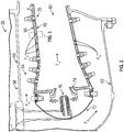
FIG. 2 is an enlarged sectional view of a combustor of a combustor section of the gas turbine engine ofFIG. 1 ; -
FIG. 3 is a section view of a portion of a panel assembly of the combustor ofFIG. 2 ; -
FIG. 4 is a partial perspective view of the panel assembly; -
FIG. 5 is a perspective view of a pedestal of the panel assembly; and -
FIG. 6 is a top view of the pedestal of the panel assembly. - A detailed description of one or more embodiments of the disclosed apparatus and method are presented herein by way of exemplification and not limitation with reference to the Figures.
-
FIG. 1 schematically illustrates agas turbine engine 20. Thegas turbine engine 20 is disclosed herein as a two-spool turbofan that generally incorporates afan section 22, acompressor section 24, acombustor section 26 and aturbine section 28. Alternative gas turbine engines may include an augmentor section (not shown) among other systems or features. Thefan section 22 drives air along a bypass flow path B in a bypass duct, while thecompressor section 24 drives air along a core flow path C for compression and communication into thecombustor section 26 then expansion through theturbine section 28. Although depicted as a two-spool turbofan gas turbine engine in the disclosed non-limiting embodiment, it should be understood that the concepts described herein are not limited to use with two-spool turbofans as the teachings may be applied to other types of turbine engines including three-spool architectures. - The illustrative
gas turbine engine 20 generally includes alow speed spool 30 and ahigh speed spool 32 mounted for rotation about an engine central longitudinal axis A relative to an enginestatic structure 36 viaseveral bearing systems 38. It should be understood thatvarious bearing systems 38 at various locations may be alternatively or additionally provided, and the location ofbearing systems 38 may be varied as appropriate to the application. - The
low speed spool 30 generally includes aninner shaft 40 that interconnects afan 42, alow pressure compressor 44 and alow pressure turbine 46. Theinner shaft 40 is connected to thefan 42 through a speed change mechanism, which in illustrativegas turbine engine 20 is illustrated as a gearedarchitecture 48 to drive thefan 42 at a lower speed than thelow speed spool 30. Thehigh speed spool 32 includes anouter shaft 50 that interconnects ahigh pressure compressor 52 andhigh pressure turbine 54. Acombustor 56 is arranged inillustrative gas turbine 20 between thehigh pressure compressor 52 and thehigh pressure turbine 54. An enginestatic structure 36 is arranged generally between thehigh pressure turbine 54 and thelow pressure turbine 46. The enginestatic structure 36 furthersupports bearing systems 38 in theturbine section 28. Theinner shaft 40 and theouter shaft 50 are concentric and rotate via bearingsystems 38 about the engine central longitudinal axis A which is collinear with their longitudinal axes. - The core airflow is compressed by the
low pressure compressor 44 then thehigh pressure compressor 52, mixed and burned with fuel in thecombustor 56, then expanded over thehigh pressure turbine 54 andlow pressure turbine 46. Theturbines low speed spool 30 andhigh speed spool 32 in response to the expansion. It will be appreciated that each of the positions of thefan section 22,compressor section 24,combustor section 26,turbine section 28, and fandrive gear system 48 may be varied. For example,gear system 48 may be located aft ofcombustor section 26 or even aft ofturbine section 28, andfan section 22 may be positioned forward or aft of the location ofgear system 48. - The
gas turbine engine 20 in one example is a high-bypass geared aircraft engine. In a further example, thegas turbine engine 20 bypass ratio may be greater than about six (6), with an example embodiment being greater than about ten (10), the gearedarchitecture 48 is an epicyclic gear train, such as a planetary gear system or other gear system, with a gear reduction ratio of greater than about 2.3 and thelow pressure turbine 46 has a pressure ratio that is greater than about five. In one disclosed embodiment, thegas turbine engine 20 bypass ratio is greater than about ten (10:1), the fan diameter is significantly larger than that of thelow pressure compressor 44, and thelow pressure turbine 46 has a pressure ratio that is greater than about five 5:1.Low pressure turbine 46 pressure ratio is pressure measured prior to inlet oflow pressure turbine 46 as related to the pressure at the outlet of thelow pressure turbine 46 prior to an exhaust nozzle. The gearedarchitecture 48 may be an epicycle gear train, such as a planetary gear system or other gear system, with a gear reduction ratio of greater than about 2.3:1. It should be understood, however, that the above parameters are only illustrative of one embodiment of a geared architecture engine and that the present disclosure is applicable to other gas turbine engines including direct drive turbofans. - A significant amount of thrust is provided by the bypass flow B due to the high bypass ratio. The
fan section 22 of thegas turbine engine 20 is designed for a particular flight condition--typically cruise at about 0.8Mach and about 35,000 feet (10,688 meters). The flight condition of 0.8 Mach and 35,000 ft (10,688 meters), with the engine at its best fuel consumption--also known as "bucket cruise Thrust Specific Fuel Consumption ('TSFC')"--is the industry standard parameter of lbm of fuel being burned divided by lbf of thrust the engine produces at that minimum point. "Low fan pressure ratio" is the pressure ratio across the fan blade alone, without a Fan Exit Guide Vane ("FEGV") system. The low fan pressure ratio as disclosed herein according to one non-limiting embodiment is less than about 1.45. "Low corrected fan tip speed" is the actual fan tip speed in ft/sec divided by an industry standard temperature correction of [(Tram °R)/(518.7 °R)]0.5. The "Low corrected fan tip speed" as disclosed herein according to one non-limiting embodiment is less than about 1150 ft/second (350.5 m/sec). - Referring to
FIG. 2 , thecombustor 56 of thecombustor section 26 of thegas turbine engine 20 is more clearly illustrated. Thecombustor 56 includes anouter shell 60 that is disposed radially outboard and disposed about aninner shell 62. Aplenum 64 is defined between theouter shell 60 andinner shell 62. Thecombustor 56 further includes apanel assembly 70 that is operatively connected to abulkhead 72 that defines a nozzle orswirler 74 that afuel nozzle 76 extends towards. - Fuel provided through the
fuel nozzle 76 mixes with air through theswirler 74 and is ignited in acombustion chamber 80 defined by thepanel assembly 70 to produce combustion gases. Thepanel assembly 70 is exposed to heat that is generated by the combustion gases as the combustion gases flow within or pass through thecombustion chamber 80. Cooling air, Fc, which flows through theplenum 64 may be used to cool portions of thepanel assembly 70. - Referring to
FIGS. 2 and3 , thepanel assembly 70 may be a combustor panel assembly that includes afirst panel 90 andsecond panel 92. Thefirst panel 90 is operatively connected to at least one of theouter shell 60 or theinner shell 62. Thefirst panel 90 is provided with afirst panel surface 100 and asecond panel surface 102 that is disposed opposite thefirst panel surface 100. Thefirst panel 90 defines a plurality ofcooling holes 104 that extend from thefirst panel surface 100 to thesecond panel surface 102 such that thefirst panel 90 is configured as an impingement panel. The plurality ofcooling holes 104 are positioned to receive or direct the cooling air, Fc, towards a surface of thesecond panel 92, to impinge on a surface of thesecond panel 92. - The
second panel 92 may be a combustor panel that includes afirst surface 110, asecond surface 112 that is disposed opposite thefirst surface 110, a mountingstud 114, and a plurality ofprotrusions 116. - The
first surface 110 faces towards thecombustion chamber 80. Thesecond surface 112 faces towards thefirst panel surface 100. The cooling air, Fc, impinges on thesecond surface 112 and flows between thefirst panel surface 100 of thefirst panel 90 and thesecond surface 112 of thesecond panel 92. - Referring to
FIGS. 3 and 4 , thesecond panel 92 is operatively connected to thefirst panel 90 by the mountingstud 114. The mountingstud 114 is disposed on thesecond surface 112 and extends from thesecond surface 112 towards thefirst panel surface 100 of thefirst panel 90. The plurality ofprotrusions 116 are disposed on thesecond surface 112 and are disposed about the mountingstud 114. The plurality ofprotrusions 116 have a height that is substantially less than the height of the mountingstud 114. - The
second panel 92 is cooled by convecting heat away from thesecond surface 112 via the cooling air, Fc. A primary cooling zone may be disposed proximate a core of the cooling air, Fc, as it enters through a cooling hole of the plurality of cooling holes 104. The core of the cooling air (referred to as the impingement jet) is collinear to thecooling hole 104. Heat transfer peaks at the primary cooling zone (within the center of the cooling jet) and then decays parabolically away from this zone. The primary cooling zone has a high heat transfer rate due to a large temperature difference between the cooling air, Fc, and thesecond surface 112. A secondary cooling zone is created away from the core of the cooling impingement jet and has a lower heat transfer rate than the primary cooling zone. The lower heat transfer rate is based on the transverse flow of the cooling air, Fc, across thesecond surface 112 and the lower temperature difference between the cooling air, Fc, and thesecond surface 112 as the cooling flow, Fc, flows across thesecond panel 92. - A plurality of
pedestals 118, such as cooling pedestals, may be provided as part of a gas turbine engine cooling arrangement that may be arranged on a surface of a component of the gas turbine engine 10 such as theouter shell 60, theinner shell 62, thebulkhead 72, theswirler 74, thefuel nozzle 76, thefirst panel 90, thesecond panel 92, within a turbine blade of theturbine section 28, or a case disposed about a section of the gas turbine engine 10 to augment the cooling of the component of the gas turbine engine 10 by creating larger convective surfaces for heat transfer to occur through and to increase the heat transfer rate from the component of the gas turbine engine 10 into the cooling flow or impingement flow. For example, should the plurality ofpedestals 118 may be disposed on thesecond panel 92, the plurality ofpedestals 118 may increase the heat transfer rate within the secondary cooling zone from thesecond panel 92 to the cooling flow, Fc. While the cooling pedestals are described as being arranged on thesecond panel 92 of thepanel assembly 70, it is also contemplated that the cooling pedestals may be disposed on another component of the gas turbine engine 10 as described above. - The plurality of
pedestals 118 are disposed on thesecond surface 112 of thesecond panel 92. In at least one embodiment, thesecond surface 112 may define a recessed region upon which the plurality ofpedestals 118 may be disposed such that a base of each pedestal of the plurality ofpedestals 118 is disposed substantially parallel to but not coplanar with at least one of the mountingstud 114 and the plurality ofprotrusions 116, as shown inFIG. 3 . The plurality pedestals 118 are disposed about or disposed proximate the plurality ofprotrusions 116 and the mountingstuds 114. The plurality ofpedestals 118 may be integrally formed with thesecond panel 92 through an additive manufacturing process. - Referring to
FIGS. 3 ,5, and 6 eachpedestal 120 of the plurality ofpedestals 118 includes anouter surface 130 that extends along afirst axis 132 between apedestal base 134 and apedestal top 136. Thefirst axis 132 is disposed orthogonal or transverse to the longitudinal axis A. A height of eachpedestal 120 of the plurality ofpedestals 118 that is measured between thepedestal base 134 andpedestal top 136 is less than one third of a distance measured between thesecond surface 112 of thesecond panel 92 and thefirst panel surface 100 of thefirst panel 90. - The
pedestal base 134 may have a width that is greater than a width of thepedestal top 136.Pedestal base 134 may be tapered such that the width becomes less in a direction that extends from thesecond surface 112 towards thepedestal top 136. In such a configuration, thepedestal base 134 may have a first width at thesecond surface 112 and a second width that is spaced apart from thesecond surface 112 that is less than the first width. - Each
pedestal 120 of the plurality ofpedestals 118 defines a plurality ofindents 140 and a plurality oflobes 142. In at least one embodiment, the plurality ofindents 140 defines the plurality oflobes 142. In at least one embodiment, the plurality oflobes 142 defines the plurality ofindents 140. - Referring to
FIGS. 5 and 6 , each indent of the plurality ofindents 140 is spaced apart from one another. Each indent of the plurality ofindents 140 extends axially (relative to the longitudinal axis A) from theouter surface 130 towards thefirst axis 132. Each indent of the plurality ofindents 140 extends along an axis that is disposed parallel to thefirst axis 132. Each indent of the plurality ofindents 140 extends radially (relative to the longitudinal axis A) along thefirst axis 132 between thepedestal base 134 and thepedestal top 136. - In an illustrative embodiment, the plurality of
indents 140 include afirst indent 150, asecond indent 152, athird indent 154, and afourth indent 156. Thefirst indent 150 extends from theouter surface 130 towards thefirst axis 132. Thesecond indent 152 is spaced apart from thefirst indent 150 and extends from theouter surface 130 towards thefirst axis 132. Thethird indent 154 is spaced apart from thefirst indent 150 and thesecond indent 152 and extends from theouter surface 130 towards thefirst axis 132. Thefourth indent 156 is spaced apart from thefirst indent 150, thesecond indent 152, and thethird indent 154 and extends from theouter surface 130 towards thefirst axis 132. - The plurality of
lobes 142 may extend radially (relative to the longitudinal axis A) between thepedestal base 134 and thepedestal top 136. In at least one embodiment, the plurality ofindents 140 may be twisted about or relative to thefirst axis 132. The plurality oflobes 142 may extend axially (relative to the longitudinal axis A) away from thefirst axis 132. In at least one embodiment, the plurality oflobes 142 may be tapered such that a width between axially aligned lobes of the plurality oflobes 142 proximate thepedestal base 134 is greater than or less than a width between the axially aligned lobes of the plurality oflobes 142 proximate thepedestal top 136. - The plurality of
lobes 142 may be defined between adjacent indents of the plurality ofindents 140. For example, in the illustrative embodiment, afirst lobe 160 is defined between thefirst indent 150 and thesecond indent 152 and asecond lobe 162 is defined between thethird indent 154 and thefourth indent 156. Thefirst lobe 160 extends along an axis that is disposed parallel to thefirst axis 132 and may extend away from thefirst axis 132. Thesecond lobe 162 is spaced apart from thefirst lobe 160. Thesecond lobe 162 extends along an axis that is disposed parallel to thefirst axis 132 and may extend away from thefirst axis 132. - A width measured between the
first lobe 160 and thesecond lobe 162 is less than a width of thepedestal base 134. - The plurality of
indents 140 and/or the plurality oflobes 142 of eachpedestal 120 of the plurality ofpedestals 118 increases the surface area of eachpedestal 120 to improve the heat transfer from thesecond panel 92 to the cooling air, Fc. The convective area of eachpedestal 120 of the plurality ofpedestals 118 is increased as compared to a pedestal that is not provided with the plurality ofindents 140 and/or the plurality oflobes 142. The increased convective area of eachpedestal 120 of the plurality ofpedestals 118 increases the convective cooling efficiency of thesecond panel 92 or other hot section components that the plurality ofpedestals 118 may be disposed upon. Furthermore, the increased convective area increases the cooling efficiency while reducing the weight for comparative area of a pedestal that is not provided with the plurality ofindents 140 and/or the plurality oflobes 142. - The term "about" is intended to include the degree of error associated with measurement of the particular quantity based upon the equipment available at the time of filing the application. For example, "about" can include a range of ± 8% or 5%, or 2% of a given value.
- The terminology used herein is for the purpose of describing particular embodiments only and is not intended to be limiting of the present disclosure. As used herein, the singular forms "a", "an" and "the" are intended to include the plural forms as well, unless the context clearly indicates otherwise. It will be further understood that the terms "comprises" and/or "comprising," when used in this specification, specify the presence of stated features, integers, steps, operations, elements, and/or components, but do not preclude the presence or addition of one or more other features, integers, steps, operations, element components, and/or groups thereof.
- While the present disclosure has been described with reference to an illustrative embodiment or embodiments, it will be understood by those skilled in the art that various changes may be made and equivalents may be substituted for elements thereof without departing from the scope of the present disclosure. In addition, many modifications may be made to adapt a particular situation or material to the teachings of the present disclosure without departing from the essential scope thereof. Therefore, it is intended that the present disclosure not be limited to the particular embodiment disclosed as the best mode contemplated for carrying out this present disclosure, but that the present disclosure will include all embodiments falling within the scope of the claims.
Claims (15)
- A gas turbine engine cooling arrangement, comprising:a component (92) of a gas turbine engine having a first surface (110) and a second surface (112) disposed opposite the first surface (110); anda pedestal (120) disposed on the second surface (112), the pedestal having an outer surface (130) extending along a first axis (132) away from the second surface (112) between a pedestal base (134) and a pedestal top (136), and a first lobe (160) is defined by the outer surface (130) and extends along an axis that is disposed parallel to the first axis (132).
- The gas turbine engine cooling arrangement of claim 1, wherein the pedestal (120) further comprising:a second lobe (162) that is defined by the outer surface (130) and is spaced apart from the first lobe (160), the second lobe (162) extends along another axis that is disposed parallel to the first axis (132).
- The gas turbine engine cooling arrangement of claim 2, wherein an indent (150, 152, 154, 156) is defined between the first lobe (160) and the second lobe (162).
- The gas turbine engine cooling arrangement of claim 1, 2 or 3, further comprising:a panel (90) spaced apart from the component (92) of the gas turbine engine , the panel (90) having a first panel surface (100) that faces towards the second surface (112) and a second panel surface (102) that is disposed opposite the first panel surface (100); and optionallywherein the panel (90) defines a plurality of cooling holes (104) that extend from the first panel surface (100) to the second panel surface (102).
- The gas turbine engine cooling arrangement of claim 4, further comprising:a mounting stud (114) disposed on the second surface (112) towards the panel (90).
- The gas turbine engine cooling arrangement of claim 5, further comprising:a plurality of protrusions (116) disposed on the second surface (112) and disposed about the mounting stud (114); and optionallywherein the pedestal (120) is provided as part of a plurality of pedestals (118) that are disposed about the plurality of protrusions (116); and/or optionallywherein a height of the pedestal (120) measured between the pedestal top (136) and the pedestal base (134) is less than one third of a distance measured between the second surface (112) and the first panel surface (100).
- A gas turbine engine cooling arrangement, comprising:a pedestal (120) having an outer surface (130) extending along a first axis (132) away from a surface (112) of a component (92) of a gas turbine engine between a pedestal base (134) and a pedestal top (136), the pedestal (120) defining a plurality of indents (140) that are spaced apart from each other.
- The gas turbine engine cooling arrangement of claim 7, wherein each indent (150, 152, 154, 156) of the plurality of indents (140) extend axially from the outer surface (130) towards the first axis (132).
- The gas turbine engine cooling arrangement of claim 7 or 8, wherein each indent (150, 152, 154, 156) of the plurality of indents (140) extend radially between the pedestal base (134) and the pedestal top (136).
- The gas turbine engine cooling arrangement of claim 9, wherein the plurality of indents (140) define a plurality of lobes (142).
- A gas turbine engine, comprising:a first panel (90) connected to a shell, the first panel (90) having a first panel surface (100) and a second panel surface (102) that is disposed opposite the first panel surface (100),a second panel (92) operatively connected to the first panel (90), the second panel (92) having a first surface (110) and a second surface (112) disposed opposite the first surface (110) that faces towards the first panel surface (100), anda plurality of pedestals (118) disposed on the second surface (112), each pedestal (120) of the plurality of pedestals (118) having an outer surface (130) extending along a first axis (132) from the second surface (112) towards the first panel surface (100), each pedestal (120) of the plurality of pedestals (118) defining a first indent (150) that extends from the outer surface (130) towards the first axis (132).
- The gas turbine engine of claim 11, wherein each pedestal (120) of the plurality of pedestals (118) further defining a second indent (152) that is spaced apart from the first indent (150) and extends from the outer surface (130) towards the first axis (132).
- The gas turbine engine of claim 12, wherein a first lobe (160) is defined between the first indent (150) and the second indent (152).
- The gas turbine engine of claim 13, wherein each pedestal (120) of the plurality of pedestals (118) further defining a third indent (154) that is spaced apart from the first indent (150) and the second indent (152), the third indent (154) extends from the outer surface (130) towards the first axis (132).
- The gas turbine engine of claim 14, wherein each pedestal (120) of the plurality of pedestals (118) further defining a fourth indent (156) that is spaced apart from the third indent (154), the fourth indent (156) extends from the outer surface (130) towards the first axis (132); and optionally wherein a second lobe (162) is defined between the third indent (154) and the fourth indent (156).
Applications Claiming Priority (1)
| Application Number | Priority Date | Filing Date | Title |
|---|---|---|---|
| US15/668,135 US20190040796A1 (en) | 2017-08-03 | 2017-08-03 | Gas turbine engine cooling arrangement |
Publications (2)
| Publication Number | Publication Date |
|---|---|
| EP3438538A2 true EP3438538A2 (en) | 2019-02-06 |
| EP3438538A3 EP3438538A3 (en) | 2019-03-06 |
Family
ID=63144912
Family Applications (1)
| Application Number | Title | Priority Date | Filing Date |
|---|---|---|---|
| EP18187310.0A Withdrawn EP3438538A3 (en) | 2017-08-03 | 2018-08-03 | Gas turbine engine cooling arrangement |
Country Status (2)
| Country | Link |
|---|---|
| US (1) | US20190040796A1 (en) |
| EP (1) | EP3438538A3 (en) |
Families Citing this family (1)
| Publication number | Priority date | Publication date | Assignee | Title |
|---|---|---|---|---|
| EP4293308B1 (en) * | 2022-06-14 | 2024-12-18 | Hamilton Sundstrand Corporation | Heat exchanger core layer |
Family Cites Families (14)
| Publication number | Priority date | Publication date | Assignee | Title |
|---|---|---|---|---|
| US5353865A (en) * | 1992-03-30 | 1994-10-11 | General Electric Company | Enhanced impingement cooled components |
| US6402470B1 (en) * | 1999-10-05 | 2002-06-11 | United Technologies Corporation | Method and apparatus for cooling a wall within a gas turbine engine |
| US9133715B2 (en) * | 2006-09-20 | 2015-09-15 | United Technologies Corporation | Structural members in a pedestal array |
| JP5696566B2 (en) * | 2011-03-31 | 2015-04-08 | 株式会社Ihi | Combustor for gas turbine engine and gas turbine engine |
| JP5834876B2 (en) * | 2011-12-15 | 2015-12-24 | 株式会社Ihi | Impinge cooling mechanism, turbine blade and combustor |
| US20160025010A1 (en) * | 2013-03-26 | 2016-01-28 | United Technologies Corporation | Turbine engine and turbine engine component with cooling pedestals |
| US10247099B2 (en) * | 2013-10-29 | 2019-04-02 | United Technologies Corporation | Pedestals with heat transfer augmenter |
| US10690348B2 (en) * | 2013-11-04 | 2020-06-23 | Raytheon Technologies Corporation | Turbine engine combustor heat shield with one or more cooling elements |
| US10234140B2 (en) * | 2013-12-31 | 2019-03-19 | United Technologies Corporation | Gas turbine engine wall assembly with enhanced flow architecture |
| US20170003027A1 (en) * | 2014-01-31 | 2017-01-05 | United Technologies Corporation | Gas turbine engine combustor liner panel with synergistic cooling features |
| US9851105B2 (en) * | 2014-07-03 | 2017-12-26 | United Technologies Corporation | Self-cooled orifice structure |
| US10196900B2 (en) * | 2014-12-15 | 2019-02-05 | United Technologies Corporation | Heat transfer pedestals with flow guide features |
| US20170167381A1 (en) * | 2015-12-15 | 2017-06-15 | United Technologies Corporation | Turbulators for improved cooling of gas turbine engine components |
| US20170191417A1 (en) * | 2016-01-06 | 2017-07-06 | General Electric Company | Engine component assembly |
-
2017
- 2017-08-03 US US15/668,135 patent/US20190040796A1/en not_active Abandoned
-
2018
- 2018-08-03 EP EP18187310.0A patent/EP3438538A3/en not_active Withdrawn
Non-Patent Citations (1)
| Title |
|---|
| None |
Also Published As
| Publication number | Publication date |
|---|---|
| US20190040796A1 (en) | 2019-02-07 |
| EP3438538A3 (en) | 2019-03-06 |
Similar Documents
| Publication | Publication Date | Title |
|---|---|---|
| EP2984317B1 (en) | Combustor panel t-junction cooling | |
| EP3366995A1 (en) | Combustor liner panel end rail cooling interface passage for a gas turbine engine combustor | |
| EP2963346B1 (en) | Self-cooled orifice structure | |
| EP3282190B1 (en) | Combustor | |
| US20160281988A1 (en) | Co-swirl orientation of combustor effusion passages for gas turbine engine combustor | |
| EP3026343A1 (en) | Self-cooled orifice structure | |
| EP3034793B1 (en) | Gas turbine engine component with increased cooling capacity | |
| EP3330611B1 (en) | Regulated combustor liner panel for a gas turbine engine combustor | |
| EP2971973B1 (en) | Combustor panel and combustor with heat shield with increased durability | |
| EP3382279B1 (en) | Washer for combustor assembly | |
| EP3663649B1 (en) | Combustor for use in a gas turbine engine | |
| EP3179040B1 (en) | Component for a gas turbine engine and corresponding a method of manufacturing a film-cooled article | |
| EP3266983A1 (en) | Cooling system for an airfoil of a gas powered turbine | |
| EP3315730B1 (en) | Combustor seal and method for a gas turbine engine combustor | |
| EP3495613A1 (en) | Cooled gas turbine engine component | |
| WO2019028241A1 (en) | Minimization of low pressure vortex in the rail between two adjacent liner panels | |
| US10655856B2 (en) | Dilution passage arrangement for gas turbine engine combustor | |
| EP3438538A2 (en) | Gas turbine engine cooling arrangement | |
| EP3640542B1 (en) | Combustor panel for a gas turbine engine with a cooling hole arrangement | |
| EP3315864B1 (en) | Cast combustor liner panel with radiused dilution passage grommet for a gas turbine engine combustor | |
| US10823410B2 (en) | Cast combustor liner panel radius for gas turbine engine combustor |
Legal Events
| Date | Code | Title | Description |
|---|---|---|---|
| PUAI | Public reference made under article 153(3) epc to a published international application that has entered the european phase |
Free format text: ORIGINAL CODE: 0009012 |
|
| STAA | Information on the status of an ep patent application or granted ep patent |
Free format text: STATUS: THE APPLICATION HAS BEEN PUBLISHED |
|
| PUAL | Search report despatched |
Free format text: ORIGINAL CODE: 0009013 |
|
| AK | Designated contracting states |
Kind code of ref document: A2 Designated state(s): AL AT BE BG CH CY CZ DE DK EE ES FI FR GB GR HR HU IE IS IT LI LT LU LV MC MK MT NL NO PL PT RO RS SE SI SK SM TR |
|
| AX | Request for extension of the european patent |
Extension state: BA ME |
|
| AK | Designated contracting states |
Kind code of ref document: A3 Designated state(s): AL AT BE BG CH CY CZ DE DK EE ES FI FR GB GR HR HU IE IS IT LI LT LU LV MC MK MT NL NO PL PT RO RS SE SI SK SM TR |
|
| AX | Request for extension of the european patent |
Extension state: BA ME |
|
| RIC1 | Information provided on ipc code assigned before grant |
Ipc: F23R 3/00 20060101AFI20190129BHEP |
|
| STAA | Information on the status of an ep patent application or granted ep patent |
Free format text: STATUS: REQUEST FOR EXAMINATION WAS MADE |
|
| 17P | Request for examination filed |
Effective date: 20190906 |
|
| RBV | Designated contracting states (corrected) |
Designated state(s): AL AT BE BG CH CY CZ DE DK EE ES FI FR GB GR HR HU IE IS IT LI LT LU LV MC MK MT NL NO PL PT RO RS SE SI SK SM TR |
|
| STAA | Information on the status of an ep patent application or granted ep patent |
Free format text: STATUS: EXAMINATION IS IN PROGRESS |
|
| 17Q | First examination report despatched |
Effective date: 20201215 |
|
| STAA | Information on the status of an ep patent application or granted ep patent |
Free format text: STATUS: THE APPLICATION HAS BEEN WITHDRAWN |
|
| RAP1 | Party data changed (applicant data changed or rights of an application transferred) |
Owner name: RAYTHEON TECHNOLOGIES CORPORATION |
|
| 18W | Application withdrawn |
Effective date: 20210315 |