EP3438479A1 - Bearing assemblies with electrodynamically matched races - Google Patents
Bearing assemblies with electrodynamically matched races Download PDFInfo
- Publication number
- EP3438479A1 EP3438479A1 EP18186836.5A EP18186836A EP3438479A1 EP 3438479 A1 EP3438479 A1 EP 3438479A1 EP 18186836 A EP18186836 A EP 18186836A EP 3438479 A1 EP3438479 A1 EP 3438479A1
- Authority
- EP
- European Patent Office
- Prior art keywords
- race
- rolling elements
- inner race
- outer race
- bearing assembly
- Prior art date
- Legal status (The legal status is an assumption and is not a legal conclusion. Google has not performed a legal analysis and makes no representation as to the accuracy of the status listed.)
- Granted
Links
Images


Classifications
-
- F—MECHANICAL ENGINEERING; LIGHTING; HEATING; WEAPONS; BLASTING
- F16—ENGINEERING ELEMENTS AND UNITS; GENERAL MEASURES FOR PRODUCING AND MAINTAINING EFFECTIVE FUNCTIONING OF MACHINES OR INSTALLATIONS; THERMAL INSULATION IN GENERAL
- F16C—SHAFTS; FLEXIBLE SHAFTS; ELEMENTS OR CRANKSHAFT MECHANISMS; ROTARY BODIES OTHER THAN GEARING ELEMENTS; BEARINGS
- F16C33/00—Parts of bearings; Special methods for making bearings or parts thereof
- F16C33/30—Parts of ball or roller bearings
- F16C33/58—Raceways; Race rings
- F16C33/583—Details of specific parts of races
- F16C33/585—Details of specific parts of races of raceways, e.g. ribs to guide the rollers
-
- B—PERFORMING OPERATIONS; TRANSPORTING
- B23—MACHINE TOOLS; METAL-WORKING NOT OTHERWISE PROVIDED FOR
- B23H—WORKING OF METAL BY THE ACTION OF A HIGH CONCENTRATION OF ELECTRIC CURRENT ON A WORKPIECE USING AN ELECTRODE WHICH TAKES THE PLACE OF A TOOL; SUCH WORKING COMBINED WITH OTHER FORMS OF WORKING OF METAL
- B23H1/00—Electrical discharge machining, i.e. removing metal with a series of rapidly recurring electrical discharges between an electrode and a workpiece in the presence of a fluid dielectric
-
- B—PERFORMING OPERATIONS; TRANSPORTING
- B23—MACHINE TOOLS; METAL-WORKING NOT OTHERWISE PROVIDED FOR
- B23H—WORKING OF METAL BY THE ACTION OF A HIGH CONCENTRATION OF ELECTRIC CURRENT ON A WORKPIECE USING AN ELECTRODE WHICH TAKES THE PLACE OF A TOOL; SUCH WORKING COMBINED WITH OTHER FORMS OF WORKING OF METAL
- B23H9/00—Machining specially adapted for treating particular metal objects or for obtaining special effects or results on metal objects
-
- F—MECHANICAL ENGINEERING; LIGHTING; HEATING; WEAPONS; BLASTING
- F16—ENGINEERING ELEMENTS AND UNITS; GENERAL MEASURES FOR PRODUCING AND MAINTAINING EFFECTIVE FUNCTIONING OF MACHINES OR INSTALLATIONS; THERMAL INSULATION IN GENERAL
- F16C—SHAFTS; FLEXIBLE SHAFTS; ELEMENTS OR CRANKSHAFT MECHANISMS; ROTARY BODIES OTHER THAN GEARING ELEMENTS; BEARINGS
- F16C19/00—Bearings with rolling contact, for exclusively rotary movement
- F16C19/02—Bearings with rolling contact, for exclusively rotary movement with bearing balls essentially of the same size in one or more circular rows
-
- F—MECHANICAL ENGINEERING; LIGHTING; HEATING; WEAPONS; BLASTING
- F16—ENGINEERING ELEMENTS AND UNITS; GENERAL MEASURES FOR PRODUCING AND MAINTAINING EFFECTIVE FUNCTIONING OF MACHINES OR INSTALLATIONS; THERMAL INSULATION IN GENERAL
- F16C—SHAFTS; FLEXIBLE SHAFTS; ELEMENTS OR CRANKSHAFT MECHANISMS; ROTARY BODIES OTHER THAN GEARING ELEMENTS; BEARINGS
- F16C19/00—Bearings with rolling contact, for exclusively rotary movement
- F16C19/02—Bearings with rolling contact, for exclusively rotary movement with bearing balls essentially of the same size in one or more circular rows
- F16C19/04—Bearings with rolling contact, for exclusively rotary movement with bearing balls essentially of the same size in one or more circular rows for radial load mainly
- F16C19/06—Bearings with rolling contact, for exclusively rotary movement with bearing balls essentially of the same size in one or more circular rows for radial load mainly with a single row or balls
-
- F—MECHANICAL ENGINEERING; LIGHTING; HEATING; WEAPONS; BLASTING
- F16—ENGINEERING ELEMENTS AND UNITS; GENERAL MEASURES FOR PRODUCING AND MAINTAINING EFFECTIVE FUNCTIONING OF MACHINES OR INSTALLATIONS; THERMAL INSULATION IN GENERAL
- F16C—SHAFTS; FLEXIBLE SHAFTS; ELEMENTS OR CRANKSHAFT MECHANISMS; ROTARY BODIES OTHER THAN GEARING ELEMENTS; BEARINGS
- F16C19/00—Bearings with rolling contact, for exclusively rotary movement
- F16C19/22—Bearings with rolling contact, for exclusively rotary movement with bearing rollers essentially of the same size in one or more circular rows, e.g. needle bearings
-
- F—MECHANICAL ENGINEERING; LIGHTING; HEATING; WEAPONS; BLASTING
- F16—ENGINEERING ELEMENTS AND UNITS; GENERAL MEASURES FOR PRODUCING AND MAINTAINING EFFECTIVE FUNCTIONING OF MACHINES OR INSTALLATIONS; THERMAL INSULATION IN GENERAL
- F16C—SHAFTS; FLEXIBLE SHAFTS; ELEMENTS OR CRANKSHAFT MECHANISMS; ROTARY BODIES OTHER THAN GEARING ELEMENTS; BEARINGS
- F16C19/00—Bearings with rolling contact, for exclusively rotary movement
- F16C19/22—Bearings with rolling contact, for exclusively rotary movement with bearing rollers essentially of the same size in one or more circular rows, e.g. needle bearings
- F16C19/24—Bearings with rolling contact, for exclusively rotary movement with bearing rollers essentially of the same size in one or more circular rows, e.g. needle bearings for radial load mainly
- F16C19/26—Bearings with rolling contact, for exclusively rotary movement with bearing rollers essentially of the same size in one or more circular rows, e.g. needle bearings for radial load mainly with a single row of rollers
-
- F—MECHANICAL ENGINEERING; LIGHTING; HEATING; WEAPONS; BLASTING
- F16—ENGINEERING ELEMENTS AND UNITS; GENERAL MEASURES FOR PRODUCING AND MAINTAINING EFFECTIVE FUNCTIONING OF MACHINES OR INSTALLATIONS; THERMAL INSULATION IN GENERAL
- F16C—SHAFTS; FLEXIBLE SHAFTS; ELEMENTS OR CRANKSHAFT MECHANISMS; ROTARY BODIES OTHER THAN GEARING ELEMENTS; BEARINGS
- F16C33/00—Parts of bearings; Special methods for making bearings or parts thereof
- F16C33/30—Parts of ball or roller bearings
- F16C33/58—Raceways; Race rings
- F16C33/64—Special methods of manufacture
-
- B—PERFORMING OPERATIONS; TRANSPORTING
- B23—MACHINE TOOLS; METAL-WORKING NOT OTHERWISE PROVIDED FOR
- B23H—WORKING OF METAL BY THE ACTION OF A HIGH CONCENTRATION OF ELECTRIC CURRENT ON A WORKPIECE USING AN ELECTRODE WHICH TAKES THE PLACE OF A TOOL; SUCH WORKING COMBINED WITH OTHER FORMS OF WORKING OF METAL
- B23H2200/00—Specific machining processes or workpieces
- B23H2200/10—Specific machining processes or workpieces for making bearings
-
- F—MECHANICAL ENGINEERING; LIGHTING; HEATING; WEAPONS; BLASTING
- F16—ENGINEERING ELEMENTS AND UNITS; GENERAL MEASURES FOR PRODUCING AND MAINTAINING EFFECTIVE FUNCTIONING OF MACHINES OR INSTALLATIONS; THERMAL INSULATION IN GENERAL
- F16C—SHAFTS; FLEXIBLE SHAFTS; ELEMENTS OR CRANKSHAFT MECHANISMS; ROTARY BODIES OTHER THAN GEARING ELEMENTS; BEARINGS
- F16C2220/00—Shaping
- F16C2220/60—Shaping by removing material, e.g. machining
- F16C2220/68—Shaping by removing material, e.g. machining by electrical discharge or electrochemical machining
-
- F—MECHANICAL ENGINEERING; LIGHTING; HEATING; WEAPONS; BLASTING
- F16—ENGINEERING ELEMENTS AND UNITS; GENERAL MEASURES FOR PRODUCING AND MAINTAINING EFFECTIVE FUNCTIONING OF MACHINES OR INSTALLATIONS; THERMAL INSULATION IN GENERAL
- F16C—SHAFTS; FLEXIBLE SHAFTS; ELEMENTS OR CRANKSHAFT MECHANISMS; ROTARY BODIES OTHER THAN GEARING ELEMENTS; BEARINGS
- F16C2361/00—Apparatus or articles in engineering in general
- F16C2361/55—Flywheel systems
Definitions
- the present disclosure relates to rotating machinery, and more particularly to bearing assemblies for rotating machinery such as reaction wheels in artificial satellites.
- Rotating machines commonly employ bearings with inner and outer raceways separated by intermediate balls or rollers to support rotary components relative to stationary components. Since mechanical loads flow through contacting surfaces of the raceways and balls or rollers during rotation the conformity ratio the of bearing, i.e., the ratio of the inner or outer raceway to the ball diameter, is selected according to the load torque and/or vibration of the application.
- bearing systems typically includes inner raceways with curvature that is larger radius than the radius of the balls. While generally satisfactory to overcome form error and roughness in most bearing assembles, "open conformity" in some bearings can reduce the load-carrying capacity due to the associated cyclical contact stresses, which can reduce the bearing fatigue life, increase the induced vibration characteristics and torque requirement of components supported by the bearing.
- a method of electro-dynamically matching a bearing assembly includes electrically separating inner and outer races from rolling elements of the bearing assembly with lubricant and rotating the inner race relative to the outer race.
- a voltage differential is applied between one of the inner and the outer races and the rolling elements the race eroded an electrical discharge event across a gap defined between at least one of the races and the rolling elements.
- the inner and outer elements can be mechanically matched to the rolling elements prior to electrically separating the inner and outer races.
- One of the inner and outer races can be fixed to a flywheel operably connected to a source of mechanical rotation.
- One of the inner and outer races can be fixed to a static structure. Minimum separation between the inner race and/or the outer race and the rolling elements can be reduced by the erosion.
- the method can include smoothing the inner race by reducing a mechanical asperity disposed on the inner race with the electrical discharge event.
- the outer race can be smoothed by reducing a mechanical asperity disposed on the outer race with the electrical discharge event.
- the voltage differential can be applied by connecting an alternating current (AC) voltage source across the inner and/or the outer races and the rolling elements.
- the voltage differential can be applied by statically charging the rotating race relative to the rolling elements.
- the voltage differential can be removed based on a comparison of one or more of a lubricant property, load, temperature, and rotational speed with a selected value.
- a bearing assembly includes an inner race arranged about an axis with a radially outer race surface, a plurality of rolling elements circumferentially distributed about the outer race surface of the inner race, and an outer race.
- the outer race has a radially inner race surface extending about the inner race with the rolling elements captive therebetween.
- One or more of the outer and inner race surfaces have an electro-dynamically eroded asperity to improve surface finish and reduce form error between the races and the rolling elements, thereby improving performance of a lubricant EHD layer defined between the race surface and the rolling elements.
- a lead can be electrically connected to the inner race.
- a lead can be electrically connected to the outer race.
- a retainer can circumferentially fix a first of the rolling elements relative to a second of the rolling elements.
- a lead can be electrically connected to the cage.
- An AC source with positive and negative terminals can be connected to the bearing assembly. The AC source negative terminal can be connected to the AC source positive terminal through the rolling elements and either or both of the inner race and the outer race.
- a flywheel fixed relative to the inner race or the outer race.
- a static structure can be connected to the other of the inner race and the outer race.
- a mechanical rotation source can be operably connected to the flywheel.
- One or more of the races and the rolling elements can include a carbide-containing metallic material.
- a lubricant can be disposed between the rolling elements, the inner race, and the outer race.
- the rolling elements can include cylindrical elements or spherical elements.
- a reaction/momentum wheel arrangement for an artificial satellite includes a flywheel and a bearing assembly as described above.
- the rolling elements and races include a carbide-containing metallic material and a lubricant is disposed between the rolling elements and the inner and outer races.
- a minimum lubricant-film distance between at least one of the inner and outer races and the rolling elements is defined between an electro-dynamically eroded asperity and one of the rolling elements.
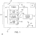
- Fig. 1 a partial view of an exemplary embodiment of a bearing assembly in accordance with the disclosure is shown in Fig. 1 and is designated generally by reference character 100.
- Other embodiments of bearing assemblies, flywheels employing bearing assemblies, and methods of making bearing assemblies in accordance with the disclosure, or aspects thereof, are provided in Figs. 2-5 , as will be described.
- the systems and methods described herein can be used reaction/momentum wheels, such as in artificial satellites, though the present disclosure is not limited to artificial satellites or to flywheels in general.
- an artificial satellite 10 is shown.
- Artificial satellite 10 includes a static structure 12, a bearing assembly 100, a flywheel 14, and a rotation source 16.
- Static structure 12 is fixed relative to flywheel 14 and can include a housing or other support structure of artificial satellite 10.
- Rotation source 16 is operably connected to flywheel 14 for applying and controlling rotation 18 of flywheel 14 relative to static structure 12 for stabilizing rotation of artificial satellite 10 about a rotation axis 20.
- Flywheel 14 is supported for rotation relative to static structure 12 by bearing assembly 100 as a reaction/momentum wheel arrangement 22 for control of artificial satellite 10 about rotation axis 20, e.g., about the x-axis.
- artificial satellite 10 can employ two or more flywheels arranged about multiples axes, e.g., the y-axis and/or the z-axis, to provide three-axis attitude control and stability to artificial satellite 10.
- axes can be oblique relative to one another, as suitable for an intended application.
- Bearing assembly 100 includes an inner race 102 arranged about rotation axis 20 with a radially outer race surface 104, a plurality of rolling elements 106 circumferentially distributed about radially outer race surface 104 of inner race 102, and an outer race 108.
- Outer race 108 has a radially inner race surface 110 that extends about inner race 102.
- Rolling elements 106 are captive between radially outer race surface 104 of inner race 102 and radially inner race surface 110 of outer race 108.
- lubricant disposed between race surfaces 102/104 and rolling elements 102 forms an elasto-hydrodynamic (EHD) layer 112 between the race surfaces 102/104 and rolling elements 102.
- EHD elasto-hydrodynamic
- outer race radially inner race surface 110 and inner race radially outer race surface 104 have an electro-dynamically eroded asperity 164 (shown in Fig. 3C ).
- Lubricant EHD layer 112 is occupied at least in part by a lubricant 114.
- a portion of lubricant 114 is disposed between rolling elements 106 and outer race 108, i.e., between rolling elements 106 and radially outer race surface 104.
- a portion of lubricant 114 is also disposed between rolling elements 106 and inner race 102, i.e., between rolling elements 106 and radially inner race surface 110.
- Examples of lubricant 114 include SHF X2000, sold under the tradename Pennzane®, available from Nye Lubricants of New Bedford, Massachusetts, which has a dielectric constant suitable for controlled erosion of race surfaces at relative low voltages for improving surface finish and/or reducing form error in mechanically matched bearing assemblies.
- outer race 108 includes a metallic material 116
- rolling elements include a metallic material 118
- outer race 108 includes a metallic material 120.
- metallic material 116, metallic material 118, and metallic material 120 include a carbide-containing metallic material.
- metallic material 120 has a metallic alloy composition that is substantially the same as metallic alloy composition of metallic material 116 and metallic material 118.
- Metallic material 118 can include, but not limited to, martensitic stainless steel materials like AISI 440C and austenitic stainless steel materials like AISI 316, AISI303, and AISI304 used in conjunction with SAE 52100 chrome steel roller elements.
- Flywheel 14 is fixed relative to inner race 102 or outer race 108.
- flywheel 14 is fixed relative to outer race 108
- inner race 102 is fixed relative to static structure 12
- rotation source 16 is connected to flywheel 14.
- flywheel 14 can be fixed to inner race 102 and outer race 108 fixed relative to static structure 12, as suitable for an intended application.
- flywheel 14 and bearing assembly 100 are supported within artificial satellite 10 in a reaction/momentum wheel arrangement 22 with lubricant 114 disposed between rolling elements 106 and inner race 102 and outer race 108.
- Form error in opposing surfaces bounding lubricant EHD layer 112 is defined between an electro-dynamically eroded asperity 164 (shown in Fig. 5 ) of one of inner race 102 and outer race 108 and one of rolling elements 106.
- vibration V associated with rotation of flywheel 14 about rotation axis 20 couples to static structure 12 through bearing assembly 100 and can influence performance of devices carried by artificial satellite 10, such as an exemplary imaging device 24.
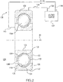
- Bearing assembly 100 includes inner race 102, first and second rolling elements 106A and 106B, a rolling element retainer 122, and outer race 108.
- Inner race 102 extends about rotation axis 20.
- Outer race 108 extends about inner race 102 and rotation axis 20.
- Rolling elements 106 circumferentially spaced about inner race 102 and rotation axis 20 and arranged radially between inner race 102 and outer race 108.
- Retainer 122 is arranged between inner race 102 and outer race 108 and retains rolling elements 106 at selected circumferential pitch about rotation axis 20. In this respect retainer 122 circumferentially fixes a first spherical rolling element 106A relative a second spherical rolling element 106B about inner race 102.
- Inner race 102 has an annular body 124 with a radially inner surface 126 and radially outer race surface 104. Annular body 124 extends about rotation axis 20. Radially inner surface 126 is arranged for fixation to static structure 12 (shown in Fig. 1 ). Radially outer race surface 104 has an electrodynamic surface portion 128 which matches surfaces of rolling elements 106 subsequent to mechanically matching inner race 102 to rolling elements 106. In the illustrated exemplary embodiment surface portion 128 is disposed only a radially outer race surface facing rolling elements 106. It is contemplated that, in certain embodiments, smoothness of radially inner surface 126 remains substantially unchanged by the process used to form surface portion 128.
- Outer race 108 has an annular body 130 with a radially outer surface 132 and radially inner race surface 110.
- Annular body 130 extends about inner race 102 and rotation axis 20.
- Radially outer surface 132 is arranged for fixation to flywheel 14 (shown in Fig. 1 ) and for common rotation with flywheel 14 about rotation axis 20.
- Radially inner race surface 110 has an electrodynamic matched surface portion 134 which matches surfaces of rolling elements 106. In the illustrated exemplary embodiment surface portion 134 is disposed only a radially outer race surface facing rolling elements 106. It is contemplated that, in certain embodiments, smoothness of radially outer surface 132 remains substantially unchanged by the process used to form surface portion 134.
- voltage source 136 for forming electrodynamically matched surface portion 128 on inner race 102 and electrodynamically matched surface portion 134 on outer race 108.
- Voltage source 136 is connected to bearing assembly through a matching circuit 138.
- matching circuit 138 includes an inner race lead 140 and an outer race lead 144.
- Inner race lead 140 connects a terminal of voltage source 136, e.g., a positive terminal 146, to inner race 102 for applying a voltage differential across inner race 102 and rolling elements 106.
- Outer race lead 144 similarly connects a terminal of voltage source 136, e.g., negative terminal 150, to outer race 130 for applying a voltage differential across outer race 130 and inner race 126.
- one of inner race 102 and outer race 108 is rotated relative to the other of inner race 102 and outer race 108, e.g., via rotation 18 (shown in Fig. 1 ) provided by rotation source 16 (shown in Fig. 1 ). While undergoing rotation, a potential difference is applied between outer race 108 and inner race 102.
- the potential difference (illustrated schematically with positive and negative signs at voltage source 136) can be applied, for example, using an AC voltage 152.
- inner race 102 can be connected to a ground terminal, such as a chassis ground terminal of artificial satellite 10 (shown in Fig. 1 ).
- the voltage differential can be applied statically.
- the electrical isolation of either inner race 102 and/or outer race 108 be interrupted and the rotating one of inner race 102 and outer race 108 permitted to develop a static charge, such as from windage of lubricant 114 (shown in Fig. 1 ) frictionally moving across the respective bearing surface.
- static electrical discharge events occur spontaneously at bearing surface asperities via rolling elements 106 according to the race surface topography, eroding race surface asperities, and thereby matching the respective bearing surface(s) to the rolling elements and develop surface portion 128 and/or surface portion 134.
- a race surface e.g., radially outer race surface 104 of inner race 102 and/or radially inner race surface 110 of outer race 108.
- inner race 102 and outer race 108 is rotated relative to rolling elements 106.
- An electrical charge develops on the inner race or outer race 108, causing a potential difference to develop across lubricant EHD layer 112.
- an electrical discharge event 162 occurs between an asperity 164 bounding EHD layer 112, as shown in Fig. 3B .
- Electrical discharge event 162 removes material from asperity 164, reducing height of asperity 164 through erosion. Removal of material from asperity 164 improves bearing surface error and reduces form error between races 102/104 and rolling elements 106, as shown in Fig. 3C . Removal of material from asperity 164 also increases the breakdown voltage of lubricant disposed between races 102/104 and rolling elements 106.
- Electrostatic discharged events 166 are more frequency and of lower voltage, as shown in Fig. 3D due to localized changes in the dielectric breakdown voltage of lubricant EHD layer 112 associated with erosion of asperity 164. This results in further smoothing of the bearing surface, as shown in Fig. 3E and improving surface finish and reduction form error between races 102/104 and rolling elements 106, discharge events eroding asperities bounding lubricant EHD layer 112 to a sweet spot corresponding to a nearly perfect 0.5 conformity ratio, as shown in Fig.
- a selected input torque results in achievement of the minimum achievable EHD operation rotational speed.
- matching can continue until a selected discharge voltage target 168, discharge frequency 170 and/or lubricant temperature target 172 is reached corresponding to a desired amount of conformity in bearing assembly 100.
- finishing can continue until such point where the surface of the inner and/or outer race matches rolling elements 106, mechanically matched and electrodynamically matched being on opposite ends of a continuum increasing conformity, electrodynamically finished surfaces having better conformity than mechanically matched surfaces, and electrodynamically matched surfaces having better conformity than electrodynamically finished surfaces.
- Method 200 includes mechanically matching and assembling inner and outer races, e.g., inner race 102 (shown in Fig. 1 ) and outer race 108 (shown in Fig. 1 ), with rolling element, e.g., rolling elements 106 (shown in Fig. 1 ), as shown with box 210.
- inner and outer races can be fixed to a flywheel, e.g., flywheel 14 (shown in Fig. 1 ), operably connected to a source of mechanical rotation, e.g., rotation source 16 (shown in Fig. 1 ).
- One of the inner and outer races can be fixed to a static structure, e.g., static structure 12 (shown in Fig. 1 ).
- Lubricant e.g., lubricant 114
- a radially outer race surface e.g., radially outer race surface 104 (shown in Fig. 1 )
- a radially inner race surface e.g., radially inner race surface 110 (shown in Fig. 1 ).
- bearing assemblies suitable for electrodynamic matching according to method 200 include ball and roller bearing assemblies available from The Barden Corporation of Danbury, Connecticut.
- One of the inner race and outer race is rotated relative to the other of the inner and outer races by applying mechanical rotation to the bearing assembly, as shown with box 220.
- a voltage differential is applied across the bearing assembly, as shown with box 230, and electrical discharge events provoked between the race and the rolling elements.
- the electrical discharge events erode asperities disposed on the race surfaces, e.g., asperity 164 (shown in Fig. 3B ), as shown with box 240. Erosion of asperity 164 improves surface finish and reduces form error between races 102/104 and rolling elements 106, improving lubricant 112 (shown in Fig. 1 ) performance, as shown with box 250.
- one or more parameter is compared to a selected parameter value, as shown with box 260.
- parameters include magnitude of electric discharge events, frequency of electrical discharge event, rotational speed realized with an input torque to the bearing assembly, and/or lubricant temperature.
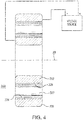
- Bearing assembly 300 is similar to bearing assembly 100 (shown in Fig. 1 ) and additionally includes cylindrical rolling elements 307.
- An inner race 302 and an outer race 308 are electrodynamically matched to cylindrical rolling elements 307, inner race 302 having a radially outer race surface 304 with an electrodynamically matched surface portion 328 and outer race 308 having a radially inner race surface 310 with an electrodynamically matched surface portion 334.
- Some bearings in rotating machinery can exhibit electrical discharge erosion. Electrical discharge erosion is an uncontrolled phenomenon wherein voltage differential builds up and dissipates across rotating and stationary bearing elements. The electrical discharge events can influence the reliability of the rotating machine by causing pitting, cratering, and/or erosion of the bearing element surfaces. For this reason bearing assemblies in rotating machines are typically electrical isolated or grounded to prevent the accumulation of an electrical potential across the bearing surfaces of the bearings.
- the potentially destructive effect of electrical discharge is applied to assembled bearing assemblies to more closely match the bearing assembly races to the rolling elements.
- a static charge is controllably developed by rotating one of the races relative to the other to provoke electric discharge events between the race surfaces and the rolling elements.
- the permitted accumulation of static charge provokes electric discharge events erode asperities on the bearing surfaces, improving race surface finish and form error between races and rolling elements bounding the lubricant EHD layer between the bearing surfaces and the rolling elements.
- a potential difference is applied to the bearing assembly to controllably generate a potential difference between the race surfaces and the rolling elements.
- the applied voltage differential provokes electric discharge events erode asperities on the bearing surfaces, improving race surface finish and reducing form error in races and rolling elements bounding the lubricant EHD layer between the bearing surfaces and the rolling elements.
- the mechanism is compensatory because erosion is influenced by the amount of stress carried by a given location as well as the instantaneous EHD layer performance within the bearing assembly.
- the smoothing takes places progressively as the low voltage induces electric discharge events at the highest asperities on the race surface, the discharge heat vaporizing the peak of the asperity participating in the electric discharge event.
- the electric discharge events remove carbide asperities via the same mechanism (and rate) as steel asperities notwithstanding the differing hardness of the materials, thereby smoothing carbide-containing steel race surfaces without leaving the surface artifacts that can remain from honing, such as with stone honing techniques.
- Matching can be accomplished by controlling one or more of lubricant properties, load, temperature, and/or rotational speed during the initial run-in of a bearing assembly.
- Voltage can be applied using a motor magnetic field, static charge accumulation form windage, or from a voltage source with controlled voltage amplitude and frequency.
- bearing assemblies with superior properties including improved race surface matching.
- Bearing assemblies electrodynamically matched with the methods described herein can have lower disturbances, higher capacity, higher fatigue life, and/or smooth surface of lower EHD liftoff speeds to reduce metal-to-metal wear during low-speed operation as compared to similar bearing assemblies run-in using different run-in techniques. While the apparatus and methods of the subject disclosure have been shown and described with reference to preferred embodiments, those skilled in the art will readily appreciate that change and/or modifications may be made thereto without departing from the scope of the subject disclosure.
Landscapes
- Engineering & Computer Science (AREA)
- General Engineering & Computer Science (AREA)
- Mechanical Engineering (AREA)
- Manufacturing & Machinery (AREA)
- Physics & Mathematics (AREA)
- Thermal Sciences (AREA)
- Rolling Contact Bearings (AREA)
Abstract
Description
- The present disclosure relates to rotating machinery, and more particularly to bearing assemblies for rotating machinery such as reaction wheels in artificial satellites.
- Rotating machines commonly employ bearings with inner and outer raceways separated by intermediate balls or rollers to support rotary components relative to stationary components. Since mechanical loads flow through contacting surfaces of the raceways and balls or rollers during rotation the conformity ratio the of bearing, i.e., the ratio of the inner or outer raceway to the ball diameter, is selected according to the load torque and/or vibration of the application.
- The machining and grinding operations used to create the raceway surfaces, raceway curvature, and spherical shape of the balls generally results in a residual amount of form error and surface roughness in the raceways and balls. Since form error and surface roughness can cause vibration, asynchronous runout, torque variation, and/or binding of the bearings, bearing systems typically includes inner raceways with curvature that is larger radius than the radius of the balls. While generally satisfactory to overcome form error and roughness in most bearing assembles, "open conformity" in some bearings can reduce the load-carrying capacity due to the associated cyclical contact stresses, which can reduce the bearing fatigue life, increase the induced vibration characteristics and torque requirement of components supported by the bearing.
- Such bearings and methods of making bearings have generally been considered satisfactory for their intended purpose. However, there is still a need in the art for improved bearing assemblies and methods of making bearing assemblies. The present disclosure provides a solution for this need.
- A method of electro-dynamically matching a bearing assembly includes electrically separating inner and outer races from rolling elements of the bearing assembly with lubricant and rotating the inner race relative to the outer race. A voltage differential is applied between one of the inner and the outer races and the rolling elements the race eroded an electrical discharge event across a gap defined between at least one of the races and the rolling elements.
- In certain embodiments, the inner and outer elements can be mechanically matched to the rolling elements prior to electrically separating the inner and outer races. One of the inner and outer races can be fixed to a flywheel operably connected to a source of mechanical rotation. One of the inner and outer races can be fixed to a static structure. Minimum separation between the inner race and/or the outer race and the rolling elements can be reduced by the erosion.
- In accordance with certain embodiments, the method can include smoothing the inner race by reducing a mechanical asperity disposed on the inner race with the electrical discharge event. The outer race can be smoothed by reducing a mechanical asperity disposed on the outer race with the electrical discharge event. The voltage differential can be applied by connecting an alternating current (AC) voltage source across the inner and/or the outer races and the rolling elements. The voltage differential can be applied by statically charging the rotating race relative to the rolling elements. The voltage differential can be removed based on a comparison of one or more of a lubricant property, load, temperature, and rotational speed with a selected value.
- A bearing assembly includes an inner race arranged about an axis with a radially outer race surface, a plurality of rolling elements circumferentially distributed about the outer race surface of the inner race, and an outer race. The outer race has a radially inner race surface extending about the inner race with the rolling elements captive therebetween. One or more of the outer and inner race surfaces have an electro-dynamically eroded asperity to improve surface finish and reduce form error between the races and the rolling elements, thereby improving performance of a lubricant EHD layer defined between the race surface and the rolling elements.
- In certain embodiments, a lead can be electrically connected to the inner race. A lead can be electrically connected to the outer race. A retainer can circumferentially fix a first of the rolling elements relative to a second of the rolling elements. A lead can be electrically connected to the cage. An AC source with positive and negative terminals can be connected to the bearing assembly. The AC source negative terminal can be connected to the AC source positive terminal through the rolling elements and either or both of the inner race and the outer race.
- In accordance with certain embodiments, a flywheel fixed relative to the inner race or the outer race. A static structure can be connected to the other of the inner race and the outer race. A mechanical rotation source can be operably connected to the flywheel. One or more of the races and the rolling elements can include a carbide-containing metallic material. A lubricant can be disposed between the rolling elements, the inner race, and the outer race. The rolling elements can include cylindrical elements or spherical elements.
- A reaction/momentum wheel arrangement for an artificial satellite includes a flywheel and a bearing assembly as described above. The rolling elements and races include a carbide-containing metallic material and a lubricant is disposed between the rolling elements and the inner and outer races. A minimum lubricant-film distance between at least one of the inner and outer races and the rolling elements is defined between an electro-dynamically eroded asperity and one of the rolling elements.
- These and other features of the systems and methods of the subject disclosure will become more readily apparent to those skilled in the art from the following detailed description of the preferred embodiments taken in conjunction with the drawings.
- So that those skilled in the art to which the subject disclosure appertains will readily understand how to make and use the devices and methods of the subject disclosure without undue experimentation, embodiments thereof will be described in detail herein below with reference to certain figures, wherein:
-
Fig. 1 is a schematic view of an exemplary embodiment of a bearing assembly constructed in accordance with the present disclosure, showing the bearing assembly supporting a flywheel in a reaction/momentum wheel arrangement in an artificial satellite; -
Fig. 2 is a cross-sectional side view of the bearing assembly ofFig. 1 , showing a voltage source connected to the bearing assembly for eroding asperities on the bearing race surfaces using electrical discharge events between the ball rolling elements and bearing races; -
Figs. 3A-3H are schematic cross-sectional views of ball and races surfaces separated by a lubricant elasto-hydrodynamic layer of the bearing assembly ofFig. 1 being matched to a rolling element electrodynamically, showing asperities of the bearing race being eroded by electric discharge events to improve performance the lubricant elasto-hydrodynamic layer between the bearing race surfaces and the rolling element; -
Fig. 4 is a is a cross-sectional side view of the bearing assembly ofFig. 1 according to a second embodiment, showing a voltage source connected to the outer and inner races for eroding asperities on the races surfaces using electrical discharge events between cylindrical rolling elements and the bearing races; and -
Fig. 5 is process flow diagram of a method of matching a bearing race to a rolling element according to the present disclosure, showing the steps of the method. - Reference will now be made to the drawings wherein like reference numerals identify similar structural features or aspects of the subject disclosure. For purposes of explanation and illustration, and not limitation, a partial view of an exemplary embodiment of a bearing assembly in accordance with the disclosure is shown in
Fig. 1 and is designated generally byreference character 100. Other embodiments of bearing assemblies, flywheels employing bearing assemblies, and methods of making bearing assemblies in accordance with the disclosure, or aspects thereof, are provided inFigs. 2-5 , as will be described. The systems and methods described herein can be used reaction/momentum wheels, such as in artificial satellites, though the present disclosure is not limited to artificial satellites or to flywheels in general. - Referring to
Fig. 1 , anartificial satellite 10 is shown.Artificial satellite 10 includes astatic structure 12, abearing assembly 100, a flywheel 14, and arotation source 16.Static structure 12 is fixed relative to flywheel 14 and can include a housing or other support structure ofartificial satellite 10.Rotation source 16 is operably connected to flywheel 14 for applying and controllingrotation 18 of flywheel 14 relative tostatic structure 12 for stabilizing rotation ofartificial satellite 10 about arotation axis 20. Flywheel 14 is supported for rotation relative tostatic structure 12 bybearing assembly 100 as a reaction/momentum wheel arrangement 22 for control ofartificial satellite 10 aboutrotation axis 20, e.g., about the x-axis. Although a single flywheel 14 is shown for x-axis control, it is to be understood and appreciated thatartificial satellite 10 can employ two or more flywheels arranged about multiples axes, e.g., the y-axis and/or the z-axis, to provide three-axis attitude control and stability toartificial satellite 10. Although shown as an orthogonal axis arrangement, it is to be understood and appreciated that the axes can be oblique relative to one another, as suitable for an intended application. - With continuing reference to
Fig. 1 ,bearing assembly 100 is shown.Bearing assembly 100 includes aninner race 102 arranged aboutrotation axis 20 with a radiallyouter race surface 104, a plurality of rollingelements 106 circumferentially distributed about radiallyouter race surface 104 ofinner race 102, and anouter race 108.Outer race 108 has a radiallyinner race surface 110 that extends aboutinner race 102.Rolling elements 106 are captive between radiallyouter race surface 104 ofinner race 102 and radiallyinner race surface 110 ofouter race 108. - As will be appreciated by those of skill in the art in view of the present disclosure, lubricant disposed between race surfaces 102/104 and rolling
elements 102 forms an elasto-hydrodynamic (EHD)layer 112 between the race surfaces 102/104 and rollingelements 102. Either or both of outer race radiallyinner race surface 110 and inner race radiallyouter race surface 104 have an electro-dynamically eroded asperity 164 (shown inFig. 3C ). Since performance of thelubricant EHD layer 112 is a function of rotational speed and form of bearingassembly 100, reducing form error within bearingassembly 100 by smoothing opposing surfaces between race surfaces 102/104 and rollingelements 102 improves the least-hydrodynamic liftoff speed of bearingassembly 100, which is driven by a ratio of film thickness and surface finish, i.e., the lambda ratio of bearingassembly 100. Improving the least-hydrodynamic liftoff speed of bearing assembly reduces vibration in bearingassembly 100 during vibration, which in turn can improve vibration-sensitive devices coupled to bearingassembly 100, such asimaging device 24. -
Lubricant EHD layer 112 is occupied at least in part by alubricant 114. A portion oflubricant 114 is disposed between rollingelements 106 andouter race 108, i.e., between rollingelements 106 and radiallyouter race surface 104. A portion oflubricant 114 is also disposed between rollingelements 106 andinner race 102, i.e., between rollingelements 106 and radiallyinner race surface 110. Examples oflubricant 114 include SHF X2000, sold under the tradename Pennzane®, available from Nye Lubricants of New Bedford, Massachusetts, which has a dielectric constant suitable for controlled erosion of race surfaces at relative low voltages for improving surface finish and/or reducing form error in mechanically matched bearing assemblies. - In the illustrated exemplary embodiment
outer race 108 includes ametallic material 116, rolling elements include ametallic material 118, andouter race 108 includes ametallic material 120. It is contemplated that one or more ofmetallic material 116,metallic material 118, andmetallic material 120 include a carbide-containing metallic material. In accordance with certain embodiments,metallic material 120 has a metallic alloy composition that is substantially the same as metallic alloy composition ofmetallic material 116 andmetallic material 118.Metallic material 118 can include, but not limited to, martensitic stainless steel materials like AISI 440C and austenitic stainless steel materials like AISI 316, AISI303, and AISI304 used in conjunction with SAE 52100 chrome steel roller elements. - Flywheel 14 is fixed relative to
inner race 102 orouter race 108. In the illustrated exemplary embodiment flywheel 14 is fixed relative toouter race 108,inner race 102 is fixed relative tostatic structure 12, androtation source 16 is connected to flywheel 14. As will be appreciated by those of skill in the art in view of the present disclosure, flywheel 14 can be fixed toinner race 102 andouter race 108 fixed relative tostatic structure 12, as suitable for an intended application. - As shown in
Fig. 1 , flywheel 14 and bearingassembly 100 are supported withinartificial satellite 10 in a reaction/momentum wheel arrangement 22 withlubricant 114 disposed between rollingelements 106 andinner race 102 andouter race 108. Form error in opposing surfaces boundinglubricant EHD layer 112 is defined between an electro-dynamically eroded asperity 164 (shown inFig. 5 ) of one ofinner race 102 andouter race 108 and one of rollingelements 106. As will also be appreciated by those of skill in the art in view of the present disclosure, vibration V associated with rotation of flywheel 14 aboutrotation axis 20 couples tostatic structure 12 through bearingassembly 100 and can influence performance of devices carried byartificial satellite 10, such as anexemplary imaging device 24. Reducing form error in either (or both)inner race 102 andouter race 108lubricant EHD layer 112 between an electro-dynamically erodedasperity 164 of one ofinner race 102 andouter race 108 and one of rollingelements 106 reduces magnitude of vibration V, improving performance ofimaging device 24. - With reference to
Fig. 2 , bearingassembly 100 is shown.Bearing assembly 100 includesinner race 102, first and secondrolling elements element retainer 122, andouter race 108.Inner race 102 extends aboutrotation axis 20.Outer race 108 extends aboutinner race 102 androtation axis 20.Rolling elements 106 circumferentially spaced aboutinner race 102 androtation axis 20 and arranged radially betweeninner race 102 andouter race 108.Retainer 122 is arranged betweeninner race 102 andouter race 108 and retains rollingelements 106 at selected circumferential pitch aboutrotation axis 20. In thisrespect retainer 122 circumferentially fixes a firstspherical rolling element 106A relative a second spherical rollingelement 106B aboutinner race 102. -
Inner race 102 has an annular body 124 with a radiallyinner surface 126 and radiallyouter race surface 104. Annular body 124 extends aboutrotation axis 20. Radiallyinner surface 126 is arranged for fixation to static structure 12 (shown inFig. 1 ). Radiallyouter race surface 104 has anelectrodynamic surface portion 128 which matches surfaces of rollingelements 106 subsequent to mechanically matchinginner race 102 to rollingelements 106. In the illustrated exemplaryembodiment surface portion 128 is disposed only a radially outer race surface facing rollingelements 106. It is contemplated that, in certain embodiments, smoothness of radiallyinner surface 126 remains substantially unchanged by the process used to formsurface portion 128. -
Outer race 108 has anannular body 130 with a radiallyouter surface 132 and radiallyinner race surface 110.Annular body 130 extends aboutinner race 102 androtation axis 20. Radiallyouter surface 132 is arranged for fixation to flywheel 14 (shown inFig. 1 ) and for common rotation with flywheel 14 aboutrotation axis 20. Radiallyinner race surface 110 has an electrodynamic matchedsurface portion 134 which matches surfaces of rollingelements 106. In the illustrated exemplaryembodiment surface portion 134 is disposed only a radially outer race surface facing rollingelements 106. It is contemplated that, in certain embodiments, smoothness of radiallyouter surface 132 remains substantially unchanged by the process used to formsurface portion 134. - Also shown in
Fig. 2 isvoltage source 136 for forming electrodynamically matchedsurface portion 128 oninner race 102 and electrodynamically matchedsurface portion 134 onouter race 108.Voltage source 136 is connected to bearing assembly through amatching circuit 138. In the illustrated exemplaryembodiment matching circuit 138 includes aninner race lead 140 and anouter race lead 144.Inner race lead 140 connects a terminal ofvoltage source 136, e.g., apositive terminal 146, toinner race 102 for applying a voltage differential acrossinner race 102 and rollingelements 106.Outer race lead 144 similarly connects a terminal ofvoltage source 136, e.g.,negative terminal 150, toouter race 130 for applying a voltage differential acrossouter race 130 andinner race 126. - Once matching
circuit 138 is established one ofinner race 102 andouter race 108 is rotated relative to the other ofinner race 102 andouter race 108, e.g., via rotation 18 (shown inFig. 1 ) provided by rotation source 16 (shown inFig. 1 ). While undergoing rotation, a potential difference is applied betweenouter race 108 andinner race 102. The potential difference (illustrated schematically with positive and negative signs at voltage source 136) can be applied, for example, using an AC voltage 152. - As a selected amount of rotational energy is applied electrical discharge events occur spontaneously at bearing surface asperities via rolling
elements 106 according to the race surface topography, eroding race surface asperities, and thereby matching the respective bearing surface(s) to the rolling elements and developsurface portion 128 and/orsurface portion 134. Although illustrated inFig. 2 as being directly connected to power sourcenegative terminal 150, those of skill in the art will appreciate in view of the present disclosure thatinner race 102 can be connected to a ground terminal, such as a chassis ground terminal of artificial satellite 10 (shown inFig. 1 ). - In certain embodiments, the voltage differential can be applied statically. In this respect it is contemplated that the electrical isolation of either
inner race 102 and/orouter race 108 be interrupted and the rotating one ofinner race 102 andouter race 108 permitted to develop a static charge, such as from windage of lubricant 114 (shown inFig. 1 ) frictionally moving across the respective bearing surface. As a selected amount of rotational energy is applied static electrical discharge events occur spontaneously at bearing surface asperities via rollingelements 106 according to the race surface topography, eroding race surface asperities, and thereby matching the respective bearing surface(s) to the rolling elements and developsurface portion 128 and/orsurface portion 134. - With reference to
Figs. 3A-3H , formation of a race surface, e.g., radiallyouter race surface 104 ofinner race 102 and/or radiallyinner race surface 110 ofouter race 108, is shown. As shown inFig. 3A , at the beginning of the matching (or electrodynamic run-in process)inner race 102 andouter race 108 is rotated relative to rollingelements 106. An electrical charge develops on the inner race orouter race 108, causing a potential difference to develop acrosslubricant EHD layer 112. When the potential difference exceeds the dielectric breakdown strength of lubricant formingEHD layer 112 anelectrical discharge event 162 occurs between anasperity 164bounding EHD layer 112, as shown inFig. 3B .Electrical discharge event 162 removes material fromasperity 164, reducing height ofasperity 164 through erosion. Removal of material fromasperity 164 improves bearing surface error and reduces form error betweenraces 102/104 and rollingelements 106, as shown inFig. 3C . Removal of material fromasperity 164 also increases the breakdown voltage of lubricant disposed betweenraces 102/104 and rollingelements 106. - As shown in
Fig. 3D , as the dominant asperities are eroded the matching process becomes dominated byelectrostatic discharge events 166. Electrostatic dischargedevents 166 are more frequency and of lower voltage, as shown inFig. 3D due to localized changes in the dielectric breakdown voltage oflubricant EHD layer 112 associated with erosion ofasperity 164. This results in further smoothing of the bearing surface, as shown inFig. 3E and improving surface finish and reduction form error betweenraces 102/104 and rollingelements 106, discharge events eroding asperities boundinglubricant EHD layer 112 to a sweet spot corresponding to a nearly perfect 0.5 conformity ratio, as shown inFig. 3F , e.g., where a selected input torque results in achievement of the minimum achievable EHD operation rotational speed. As shown inFigs. 3G and 3F , matching can continue until a selecteddischarge voltage target 168,discharge frequency 170 and/orlubricant temperature target 172 is reached corresponding to a desired amount of conformity in bearingassembly 100. As shown inFig. 3H , finishing can continue until such point where the surface of the inner and/or outer racematches rolling elements 106, mechanically matched and electrodynamically matched being on opposite ends of a continuum increasing conformity, electrodynamically finished surfaces having better conformity than mechanically matched surfaces, and electrodynamically matched surfaces having better conformity than electrodynamically finished surfaces. - Referring now to
Fig. 5 , amethod 200 of electrodynamically matching a bearing assembly, e.g., bearingassembly 100, is shown.Method 200 includes mechanically matching and assembling inner and outer races, e.g., inner race 102 (shown inFig. 1 ) and outer race 108 (shown inFig. 1 ), with rolling element, e.g., rolling elements 106 (shown inFig. 1 ), as shown withbox 210. One of the inner and outer races can be fixed to a flywheel, e.g., flywheel 14 (shown inFig. 1 ), operably connected to a source of mechanical rotation, e.g., rotation source 16 (shown inFig. 1 ). One of the inner and outer races can be fixed to a static structure, e.g., static structure 12 (shown inFig. 1 ). Lubricant, e.g.,lubricant 114, is interposed between the rolling elements a radially outer race surface, radially outer race surface 104 (shown inFig. 1 ), and a radially inner race surface, e.g., radially inner race surface 110 (shown inFig. 1 ). Examples of bearing assemblies suitable for electrodynamic matching according tomethod 200 include ball and roller bearing assemblies available from The Barden Corporation of Danbury, Connecticut. - One of the inner race and outer race is rotated relative to the other of the inner and outer races by applying mechanical rotation to the bearing assembly, as shown with
box 220. A voltage differential is applied across the bearing assembly, as shown withbox 230, and electrical discharge events provoked between the race and the rolling elements. The electrical discharge events erode asperities disposed on the race surfaces, e.g., asperity 164 (shown inFig. 3B ), as shown withbox 240. Erosion ofasperity 164 improves surface finish and reduces form error betweenraces 102/104 and rollingelements 106, improving lubricant 112 (shown inFig. 1 ) performance, as shown withbox 250. - As the voltage differential is applied to the bearing assembly one or more parameter is compared to a selected parameter value, as shown with
box 260. Examples of parameters include magnitude of electric discharge events, frequency of electrical discharge event, rotational speed realized with an input torque to the bearing assembly, and/or lubricant temperature. When the comparison indicates that the selected parameter has not been reached application of the voltage continues, as shown withdecision box 262 andarrow 270. When the comparison indicates that the selected parameter has been reached the voltage is removed, as shown witharrow 280 andbox 290. - With reference to
Fig. 4 , a bearingassembly 300 is shown.Bearing assembly 300 is similar to bearing assembly 100 (shown inFig. 1 ) and additionally includes cylindricalrolling elements 307. Aninner race 302 and anouter race 308 are electrodynamically matched to cylindricalrolling elements 307,inner race 302 having a radially outer race surface 304 with an electrodynamically matchedsurface portion 328 andouter race 308 having a radially inner race surface 310 with an electrodynamically matchedsurface portion 334. - Some bearings in rotating machinery can exhibit electrical discharge erosion. Electrical discharge erosion is an uncontrolled phenomenon wherein voltage differential builds up and dissipates across rotating and stationary bearing elements. The electrical discharge events can influence the reliability of the rotating machine by causing pitting, cratering, and/or erosion of the bearing element surfaces. For this reason bearing assemblies in rotating machines are typically electrical isolated or grounded to prevent the accumulation of an electrical potential across the bearing surfaces of the bearings.
- In embodiments described herein the potentially destructive effect of electrical discharge is applied to assembled bearing assemblies to more closely match the bearing assembly races to the rolling elements. In certain embodiments a static charge is controllably developed by rotating one of the races relative to the other to provoke electric discharge events between the race surfaces and the rolling elements. The permitted accumulation of static charge provokes electric discharge events erode asperities on the bearing surfaces, improving race surface finish and form error between races and rolling elements bounding the lubricant EHD layer between the bearing surfaces and the rolling elements. In accordance with certain embodiments, a potential difference is applied to the bearing assembly to controllably generate a potential difference between the race surfaces and the rolling elements. The applied voltage differential provokes electric discharge events erode asperities on the bearing surfaces, improving race surface finish and reducing form error in races and rolling elements bounding the lubricant EHD layer between the bearing surfaces and the rolling elements.
- Without being limited to a particular mechanism, it is believed that application of relative low voltages to bearing assemblies can constructively smooth race surfaces of the bearing assembly. In particular, application of relatively low voltages to bearing assemblies can gently erode the bearing race surface in a way that is compensatory in relation to the rolling elements of the bearing assembly subsequent to assembly to more closely conform the race to the rolling element by reducing race form error.
- It is believed that the mechanism is compensatory because erosion is influenced by the amount of stress carried by a given location as well as the instantaneous EHD layer performance within the bearing assembly. The smoothing takes places progressively as the low voltage induces electric discharge events at the highest asperities on the race surface, the discharge heat vaporizing the peak of the asperity participating in the electric discharge event. Advantageously, the electric discharge events remove carbide asperities via the same mechanism (and rate) as steel asperities notwithstanding the differing hardness of the materials, thereby smoothing carbide-containing steel race surfaces without leaving the surface artifacts that can remain from honing, such as with stone honing techniques. Matching can be accomplished by controlling one or more of lubricant properties, load, temperature, and/or rotational speed during the initial run-in of a bearing assembly. Voltage can be applied using a motor magnetic field, static charge accumulation form windage, or from a voltage source with controlled voltage amplitude and frequency.
- The methods and systems of the present disclosure, as described above and shown in the drawings, provide for bearing assemblies with superior properties including improved race surface matching. Bearing assemblies electrodynamically matched with the methods described herein can have lower disturbances, higher capacity, higher fatigue life, and/or smooth surface of lower EHD liftoff speeds to reduce metal-to-metal wear during low-speed operation as compared to similar bearing assemblies run-in using different run-in techniques. While the apparatus and methods of the subject disclosure have been shown and described with reference to preferred embodiments, those skilled in the art will readily appreciate that change and/or modifications may be made thereto without departing from the scope of the subject disclosure.
Claims (15)
- A method of electro-dynamically matching a bearing assembly (100), comprising:electrically separating inner (102) and outer races (108) from rolling elements (106) with lubricant (114);rotating the inner race (102) relative to the outer race (108);applying a voltage differential across the inner race (102) and the outer race (108); anderoding at least one of the inner race (102) and the outer race (108) with an electrical discharge event across a lubricant disposed between the one inner race (102) or the outer race (108) and a rolling element (106).
- The method as recited in claim 1, further comprising mechanically matching the inner (102) and outer races (108) to the rolling elements (106) prior to electrically separating the inner (102) and outer races (108).
- The method as recited in claim 1 or 2, further comprising seating one of the inner race (102) and the outer race (108) in a flywheel operably connected to a source of mechanical rotation, and preferably further comprising seating the other of the inner race (102) and the outer race (108) a shaft that is static relative to the flywheel (14).
- The method as recited in any preceding claim, further comprising reducing a minimum speed to achieve elasto-hydrodynamic operation between the inner race (102) and the rolling elements (114), or further comprising reducing a minimum speed to achieve elasto-hydrodynamic operation between the outer race (108) and the rolling elements (106).
- The method as recited in any preceding claim, further comprising smoothing the inner race (102) by reducing one or more mechanical asperity disposed on the inner race (102) with an uncontrolled electrical discharge event, or further comprising smoothing the outer race (108) by reducing a mechanical asperity disposed on the outer race (108) with an uncontrolled electrical discharge event.
- The method as recited in any preceding claim, wherein applying the voltage differential includes applying an alternating current voltage differential across the inner race (102) and the outer race (108).
- The method as recited in any preceding claim, further comprising removing the voltage potential by comparison of one or more of a lubricant property, load, temperature, and rotational speed with a selected value.
- A bearing assembly (100), comprising:an inner race (102) arranged about an axis with a radially outer race surface;a plurality of rolling elements (106) circumferentially distributed about the outer race (108) surface of the inner race (102); andan outer race (108) with a radially inner race surface extending about the inner race (102) with the rolling elements (106) captive therebetween,wherein at least one of the outer race surface and the inner race surface has an electro-dynamically eroded asperity bounding a lubricant EHD layer defined between the race surface and the rolling elements (106).
- The bearing assembly as recited in claim 8, further comprising a lead electrically connected to the inner race (102).
- The bearing assembly as recited in claim 8 or 9, further comprising a lead electrically connected to the outer race (108).
- The bearing assembly as recited in claim 8, 9 or 10, further comprising an alternative current (AC) source with a positive and a negative terminal, wherein the positive terminal is electrically connected to the negative terminal through the inner race (102) and the outer race (108).
- The bearing assembly as recited in any of claims 8 to 11, further comprising a flywheel (12) fixed relative to one of the inner race (102) and the outer race (108) and a static structure connected to the other of the inner race (102) and the outer race (108), and preferably further comprising a mechanical rotation source operably connected to the flywheel (12).
- The bearing assembly as recited in any of claims 8 to 12, wherein at least one of the inner race (102), the outer race (108), and the rolling elements (106) comprises a carbide-containing metallic material.
- The bearing assembly as recited in any of claims 8 to 13, further comprising a lubricant disposed between the rolling elements (106), the inner race (102), and the outer race (108).
- A reaction/momentum wheel arrangement for an artificial satellite, comprising:a flywheel (12); anda bearing assembly (100) as recited in any of claims 8 to 14 with a lubricant (114) disposed between the rolling elements (106) and the inner (102) and outer races (108), wherein the rolling elements (106) and inner (102) and outer races (108) include a carbide-containing metallic material,wherein a minimum lubricant-film distance between at least one of the inner (102) and outer races (108) and the rolling elements (106) is defined between an electro-dynamically eroded asperity and one of the rolling elements (106).
Applications Claiming Priority (1)
| Application Number | Priority Date | Filing Date | Title |
|---|---|---|---|
| US15/668,663 US10371208B2 (en) | 2017-08-03 | 2017-08-03 | Bearing assemblies with electrodynamically matched races |
Publications (2)
| Publication Number | Publication Date |
|---|---|
| EP3438479A1 true EP3438479A1 (en) | 2019-02-06 |
| EP3438479B1 EP3438479B1 (en) | 2021-07-07 |
Family
ID=63142968
Family Applications (1)
| Application Number | Title | Priority Date | Filing Date |
|---|---|---|---|
| EP18186836.5A Active EP3438479B1 (en) | 2017-08-03 | 2018-08-01 | Bearing assemblies with electrodynamically matched races |
Country Status (2)
| Country | Link |
|---|---|
| US (1) | US10371208B2 (en) |
| EP (1) | EP3438479B1 (en) |
Citations (5)
| Publication number | Priority date | Publication date | Assignee | Title |
|---|---|---|---|---|
| JP2003120692A (en) * | 2001-10-18 | 2003-04-23 | Nakanishi Metal Works Co Ltd | Manufacturing method of metal ball cage for bearing |
| WO2012114847A1 (en) * | 2011-02-24 | 2012-08-30 | Ntn株式会社 | Planetary gear device |
| KR20140004951A (en) * | 2012-07-03 | 2014-01-14 | 주식회사 일진글로벌 | Method for machining raceway surface of bearing |
| WO2015128973A1 (en) * | 2014-02-26 | 2015-09-03 | 日本精工株式会社 | Anti-friction bearing |
| WO2015146689A1 (en) * | 2014-03-25 | 2015-10-01 | Ntn株式会社 | Bearing component internal defect inspection apparatus and internal defect inspection method |
Family Cites Families (13)
| Publication number | Priority date | Publication date | Assignee | Title |
|---|---|---|---|---|
| US2782160A (en) | 1951-03-24 | 1957-02-19 | Hudson Electrochemical Company | Electropolishing apparatus |
| US3900374A (en) * | 1968-04-08 | 1975-08-19 | Cincinnati Milacron Inc | Method of electrochemical machining |
| US3547796A (en) | 1968-12-24 | 1970-12-15 | Atomic Energy Commission | Apparatus for electropolishing spherical surfaces |
| US4601802A (en) | 1984-07-31 | 1986-07-22 | The Upjohn Company | Apparatus for internally electropolishing tubes |
| JPH1044008A (en) | 1996-05-27 | 1998-02-17 | Nippon Seiko Kk | Method and apparatus for polishing spherical body and method for forming annular groove |
| NL1003233C2 (en) * | 1996-05-30 | 1997-12-03 | Skf Ind Trading & Dev | A method for manufacturing a bearing ring and a bearing comprising such a bearing ring. |
| US6217726B1 (en) | 1997-05-22 | 2001-04-17 | Therma Corporation, Inc. | Tube inner surface electropolishing device with electrolyte dam |
| US7374644B2 (en) | 2000-02-17 | 2008-05-20 | Applied Materials, Inc. | Conductive polishing article for electrochemical mechanical polishing |
| JP4141114B2 (en) * | 2000-07-05 | 2008-08-27 | 株式会社荏原製作所 | Electrolytic processing method and apparatus |
| JP2002188646A (en) | 2000-12-20 | 2002-07-05 | Nsk Ltd | Rolling bearing and bearing device |
| US20080210571A1 (en) * | 2006-08-24 | 2008-09-04 | Extrude Hone Corporation | Machine And Method For Electrochemically Polishing Indentations Within An Aluminum Wheel |
| DE102006062687A1 (en) * | 2006-10-30 | 2008-05-08 | Daimler Ag | Method and electrode for producing a substantially cylindrical bearing surface of a radial shaft bearing in electrically conductive material and connecting rods |
| US9322109B2 (en) * | 2013-08-01 | 2016-04-26 | Seagate Technology Llc | Electro-chemically machining with a motor part including an electrode |
-
2017
- 2017-08-03 US US15/668,663 patent/US10371208B2/en active Active
-
2018
- 2018-08-01 EP EP18186836.5A patent/EP3438479B1/en active Active
Patent Citations (5)
| Publication number | Priority date | Publication date | Assignee | Title |
|---|---|---|---|---|
| JP2003120692A (en) * | 2001-10-18 | 2003-04-23 | Nakanishi Metal Works Co Ltd | Manufacturing method of metal ball cage for bearing |
| WO2012114847A1 (en) * | 2011-02-24 | 2012-08-30 | Ntn株式会社 | Planetary gear device |
| KR20140004951A (en) * | 2012-07-03 | 2014-01-14 | 주식회사 일진글로벌 | Method for machining raceway surface of bearing |
| WO2015128973A1 (en) * | 2014-02-26 | 2015-09-03 | 日本精工株式会社 | Anti-friction bearing |
| WO2015146689A1 (en) * | 2014-03-25 | 2015-10-01 | Ntn株式会社 | Bearing component internal defect inspection apparatus and internal defect inspection method |
Also Published As
| Publication number | Publication date |
|---|---|
| US20190040909A1 (en) | 2019-02-07 |
| EP3438479B1 (en) | 2021-07-07 |
| US10371208B2 (en) | 2019-08-06 |
Similar Documents
| Publication | Publication Date | Title |
|---|---|---|
| US3467451A (en) | Resiliently mounted bearing arrangements | |
| US9528592B2 (en) | Solid-lubricated bearing assembly | |
| EP2829756B1 (en) | Auxiliary bearing of the ball bearing type for a magnetically suspended rotor system | |
| US20100247012A1 (en) | Bearing Apparatus Featuring Electrorheological Fluid Lubrication | |
| US20030021504A1 (en) | Extended load zone bearing | |
| Daniel et al. | Effect of bearings on vibration in rotating machinery | |
| JPH06241235A (en) | Roller bearing | |
| US20110249927A1 (en) | Radial bearings of increased load capacity and stability with one axially asymmetric bearing component | |
| EP3438479B1 (en) | Bearing assemblies with electrodynamically matched races | |
| JP2017150597A (en) | Rolling bearing, rolling device and manufacturing method of rolling device | |
| US20150152918A1 (en) | Bearing cage with a peripheral vibration damping ring | |
| WO2010131993A1 (en) | Method for alleviating the effect of centrifugal force on the rings of a rolling-element bearing (embodiments) and a rolling-element bearing (embodiments) | |
| Harris et al. | On the causes and effects of roller skewing in cylindrical roller bearings | |
| JP2934697B2 (en) | Anti-corrosion rolling bearing | |
| EP3438478B1 (en) | Electrodynamically finished plain bearings | |
| JP7024189B2 (en) | Conical roller bearing | |
| EP3636943B1 (en) | Rolling bearing and method for manufacturing such a rolling bearing | |
| JPH0289807A (en) | Non-round bearing | |
| Srinidhi et al. | Bearing wear due to mechanical stresses and electrical currents | |
| Shengbo et al. | Prospects for using foil bearings in centrifugal pumps in petrochemical industry | |
| KR101411614B1 (en) | Method for machining raceway surface of bearing | |
| SU1092663A1 (en) | Electric machine | |
| Tiwari et al. | Investigation of design parameters that affect the performance of angular contact ball bearing: a Review | |
| JP2000350402A (en) | Small motor for information equipment | |
| JP2023184282A (en) | radial bearing |
Legal Events
| Date | Code | Title | Description |
|---|---|---|---|
| PUAI | Public reference made under article 153(3) epc to a published international application that has entered the european phase |
Free format text: ORIGINAL CODE: 0009012 |
|
| STAA | Information on the status of an ep patent application or granted ep patent |
Free format text: STATUS: THE APPLICATION HAS BEEN PUBLISHED |
|
| AK | Designated contracting states |
Kind code of ref document: A1 Designated state(s): AL AT BE BG CH CY CZ DE DK EE ES FI FR GB GR HR HU IE IS IT LI LT LU LV MC MK MT NL NO PL PT RO RS SE SI SK SM TR |
|
| AX | Request for extension of the european patent |
Extension state: BA ME |
|
| STAA | Information on the status of an ep patent application or granted ep patent |
Free format text: STATUS: REQUEST FOR EXAMINATION WAS MADE |
|
| 17P | Request for examination filed |
Effective date: 20190806 |
|
| RBV | Designated contracting states (corrected) |
Designated state(s): AL AT BE BG CH CY CZ DE DK EE ES FI FR GB GR HR HU IE IS IT LI LT LU LV MC MK MT NL NO PL PT RO RS SE SI SK SM TR |
|
| STAA | Information on the status of an ep patent application or granted ep patent |
Free format text: STATUS: EXAMINATION IS IN PROGRESS |
|
| 17Q | First examination report despatched |
Effective date: 20191007 |
|
| REG | Reference to a national code |
Ref country code: DE Ref legal event code: R079 Ref document number: 602018019589 Country of ref document: DE Free format text: PREVIOUS MAIN CLASS: F16C0019020000 Ipc: F16C0033580000 |
|
| RIC1 | Information provided on ipc code assigned before grant |
Ipc: F16C 19/02 20060101ALI20201216BHEP Ipc: F16C 33/58 20060101AFI20201216BHEP Ipc: F16C 19/22 20060101ALI20201216BHEP Ipc: B23H 1/00 20060101ALI20201216BHEP Ipc: F16C 33/64 20060101ALI20201216BHEP |
|
| GRAP | Despatch of communication of intention to grant a patent |
Free format text: ORIGINAL CODE: EPIDOSNIGR1 |
|
| STAA | Information on the status of an ep patent application or granted ep patent |
Free format text: STATUS: GRANT OF PATENT IS INTENDED |
|
| INTG | Intention to grant announced |
Effective date: 20210128 |
|
| GRAS | Grant fee paid |
Free format text: ORIGINAL CODE: EPIDOSNIGR3 |
|
| GRAA | (expected) grant |
Free format text: ORIGINAL CODE: 0009210 |
|
| STAA | Information on the status of an ep patent application or granted ep patent |
Free format text: STATUS: THE PATENT HAS BEEN GRANTED |
|
| AK | Designated contracting states |
Kind code of ref document: B1 Designated state(s): AL AT BE BG CH CY CZ DE DK EE ES FI FR GB GR HR HU IE IS IT LI LT LU LV MC MK MT NL NO PL PT RO RS SE SI SK SM TR |
|
| REG | Reference to a national code |
Ref country code: GB Ref legal event code: FG4D |
|
| REG | Reference to a national code |
Ref country code: AT Ref legal event code: REF Ref document number: 1408859 Country of ref document: AT Kind code of ref document: T Effective date: 20210715 |
|
| REG | Reference to a national code |
Ref country code: DE Ref legal event code: R096 Ref document number: 602018019589 Country of ref document: DE |
|
| REG | Reference to a national code |
Ref country code: IE Ref legal event code: FG4D |
|
| REG | Reference to a national code |
Ref country code: LT Ref legal event code: MG9D |
|
| REG | Reference to a national code |
Ref country code: NL Ref legal event code: MP Effective date: 20210707 |
|
| REG | Reference to a national code |
Ref country code: AT Ref legal event code: MK05 Ref document number: 1408859 Country of ref document: AT Kind code of ref document: T Effective date: 20210707 |
|
| PG25 | Lapsed in a contracting state [announced via postgrant information from national office to epo] |
Ref country code: HR Free format text: LAPSE BECAUSE OF FAILURE TO SUBMIT A TRANSLATION OF THE DESCRIPTION OR TO PAY THE FEE WITHIN THE PRESCRIBED TIME-LIMIT Effective date: 20210707 Ref country code: ES Free format text: LAPSE BECAUSE OF FAILURE TO SUBMIT A TRANSLATION OF THE DESCRIPTION OR TO PAY THE FEE WITHIN THE PRESCRIBED TIME-LIMIT Effective date: 20210707 Ref country code: FI Free format text: LAPSE BECAUSE OF FAILURE TO SUBMIT A TRANSLATION OF THE DESCRIPTION OR TO PAY THE FEE WITHIN THE PRESCRIBED TIME-LIMIT Effective date: 20210707 Ref country code: RS Free format text: LAPSE BECAUSE OF FAILURE TO SUBMIT A TRANSLATION OF THE DESCRIPTION OR TO PAY THE FEE WITHIN THE PRESCRIBED TIME-LIMIT Effective date: 20210707 Ref country code: SE Free format text: LAPSE BECAUSE OF FAILURE TO SUBMIT A TRANSLATION OF THE DESCRIPTION OR TO PAY THE FEE WITHIN THE PRESCRIBED TIME-LIMIT Effective date: 20210707 Ref country code: LT Free format text: LAPSE BECAUSE OF FAILURE TO SUBMIT A TRANSLATION OF THE DESCRIPTION OR TO PAY THE FEE WITHIN THE PRESCRIBED TIME-LIMIT Effective date: 20210707 Ref country code: AT Free format text: LAPSE BECAUSE OF FAILURE TO SUBMIT A TRANSLATION OF THE DESCRIPTION OR TO PAY THE FEE WITHIN THE PRESCRIBED TIME-LIMIT Effective date: 20210707 Ref country code: BG Free format text: LAPSE BECAUSE OF FAILURE TO SUBMIT A TRANSLATION OF THE DESCRIPTION OR TO PAY THE FEE WITHIN THE PRESCRIBED TIME-LIMIT Effective date: 20211007 Ref country code: PT Free format text: LAPSE BECAUSE OF FAILURE TO SUBMIT A TRANSLATION OF THE DESCRIPTION OR TO PAY THE FEE WITHIN THE PRESCRIBED TIME-LIMIT Effective date: 20211108 Ref country code: NL Free format text: LAPSE BECAUSE OF FAILURE TO SUBMIT A TRANSLATION OF THE DESCRIPTION OR TO PAY THE FEE WITHIN THE PRESCRIBED TIME-LIMIT Effective date: 20210707 Ref country code: NO Free format text: LAPSE BECAUSE OF FAILURE TO SUBMIT A TRANSLATION OF THE DESCRIPTION OR TO PAY THE FEE WITHIN THE PRESCRIBED TIME-LIMIT Effective date: 20211007 |
|
| PG25 | Lapsed in a contracting state [announced via postgrant information from national office to epo] |
Ref country code: PL Free format text: LAPSE BECAUSE OF FAILURE TO SUBMIT A TRANSLATION OF THE DESCRIPTION OR TO PAY THE FEE WITHIN THE PRESCRIBED TIME-LIMIT Effective date: 20210707 Ref country code: LV Free format text: LAPSE BECAUSE OF FAILURE TO SUBMIT A TRANSLATION OF THE DESCRIPTION OR TO PAY THE FEE WITHIN THE PRESCRIBED TIME-LIMIT Effective date: 20210707 Ref country code: GR Free format text: LAPSE BECAUSE OF FAILURE TO SUBMIT A TRANSLATION OF THE DESCRIPTION OR TO PAY THE FEE WITHIN THE PRESCRIBED TIME-LIMIT Effective date: 20211008 |
|
| REG | Reference to a national code |
Ref country code: CH Ref legal event code: PL |
|
| REG | Reference to a national code |
Ref country code: DE Ref legal event code: R097 Ref document number: 602018019589 Country of ref document: DE |
|
| REG | Reference to a national code |
Ref country code: BE Ref legal event code: MM Effective date: 20210831 |
|
| PG25 | Lapsed in a contracting state [announced via postgrant information from national office to epo] |
Ref country code: LI Free format text: LAPSE BECAUSE OF NON-PAYMENT OF DUE FEES Effective date: 20210831 Ref country code: DK Free format text: LAPSE BECAUSE OF FAILURE TO SUBMIT A TRANSLATION OF THE DESCRIPTION OR TO PAY THE FEE WITHIN THE PRESCRIBED TIME-LIMIT Effective date: 20210707 Ref country code: CH Free format text: LAPSE BECAUSE OF NON-PAYMENT OF DUE FEES Effective date: 20210831 |
|
| PLBE | No opposition filed within time limit |
Free format text: ORIGINAL CODE: 0009261 |
|
| STAA | Information on the status of an ep patent application or granted ep patent |
Free format text: STATUS: NO OPPOSITION FILED WITHIN TIME LIMIT |
|
| PG25 | Lapsed in a contracting state [announced via postgrant information from national office to epo] |
Ref country code: SM Free format text: LAPSE BECAUSE OF FAILURE TO SUBMIT A TRANSLATION OF THE DESCRIPTION OR TO PAY THE FEE WITHIN THE PRESCRIBED TIME-LIMIT Effective date: 20210707 Ref country code: SK Free format text: LAPSE BECAUSE OF FAILURE TO SUBMIT A TRANSLATION OF THE DESCRIPTION OR TO PAY THE FEE WITHIN THE PRESCRIBED TIME-LIMIT Effective date: 20210707 Ref country code: RO Free format text: LAPSE BECAUSE OF FAILURE TO SUBMIT A TRANSLATION OF THE DESCRIPTION OR TO PAY THE FEE WITHIN THE PRESCRIBED TIME-LIMIT Effective date: 20210707 Ref country code: MC Free format text: LAPSE BECAUSE OF FAILURE TO SUBMIT A TRANSLATION OF THE DESCRIPTION OR TO PAY THE FEE WITHIN THE PRESCRIBED TIME-LIMIT Effective date: 20210707 Ref country code: LU Free format text: LAPSE BECAUSE OF NON-PAYMENT OF DUE FEES Effective date: 20210801 Ref country code: EE Free format text: LAPSE BECAUSE OF FAILURE TO SUBMIT A TRANSLATION OF THE DESCRIPTION OR TO PAY THE FEE WITHIN THE PRESCRIBED TIME-LIMIT Effective date: 20210707 Ref country code: CZ Free format text: LAPSE BECAUSE OF FAILURE TO SUBMIT A TRANSLATION OF THE DESCRIPTION OR TO PAY THE FEE WITHIN THE PRESCRIBED TIME-LIMIT Effective date: 20210707 Ref country code: AL Free format text: LAPSE BECAUSE OF FAILURE TO SUBMIT A TRANSLATION OF THE DESCRIPTION OR TO PAY THE FEE WITHIN THE PRESCRIBED TIME-LIMIT Effective date: 20210707 |
|
| 26N | No opposition filed |
Effective date: 20220408 |
|
| PG25 | Lapsed in a contracting state [announced via postgrant information from national office to epo] |
Ref country code: IT Free format text: LAPSE BECAUSE OF FAILURE TO SUBMIT A TRANSLATION OF THE DESCRIPTION OR TO PAY THE FEE WITHIN THE PRESCRIBED TIME-LIMIT Effective date: 20210707 Ref country code: IE Free format text: LAPSE BECAUSE OF NON-PAYMENT OF DUE FEES Effective date: 20210801 Ref country code: BE Free format text: LAPSE BECAUSE OF NON-PAYMENT OF DUE FEES Effective date: 20210831 |
|
| PG25 | Lapsed in a contracting state [announced via postgrant information from national office to epo] |
Ref country code: CY Free format text: LAPSE BECAUSE OF FAILURE TO SUBMIT A TRANSLATION OF THE DESCRIPTION OR TO PAY THE FEE WITHIN THE PRESCRIBED TIME-LIMIT Effective date: 20210707 |
|
| PG25 | Lapsed in a contracting state [announced via postgrant information from national office to epo] |
Ref country code: HU Free format text: LAPSE BECAUSE OF FAILURE TO SUBMIT A TRANSLATION OF THE DESCRIPTION OR TO PAY THE FEE WITHIN THE PRESCRIBED TIME-LIMIT; INVALID AB INITIO Effective date: 20180801 |
|
| PG25 | Lapsed in a contracting state [announced via postgrant information from national office to epo] |
Ref country code: MK Free format text: LAPSE BECAUSE OF FAILURE TO SUBMIT A TRANSLATION OF THE DESCRIPTION OR TO PAY THE FEE WITHIN THE PRESCRIBED TIME-LIMIT Effective date: 20210707 |
|
| PG25 | Lapsed in a contracting state [announced via postgrant information from national office to epo] |
Ref country code: TR Free format text: LAPSE BECAUSE OF FAILURE TO SUBMIT A TRANSLATION OF THE DESCRIPTION OR TO PAY THE FEE WITHIN THE PRESCRIBED TIME-LIMIT Effective date: 20210707 |
|
| PG25 | Lapsed in a contracting state [announced via postgrant information from national office to epo] |
Ref country code: MT Free format text: LAPSE BECAUSE OF FAILURE TO SUBMIT A TRANSLATION OF THE DESCRIPTION OR TO PAY THE FEE WITHIN THE PRESCRIBED TIME-LIMIT Effective date: 20210707 |
|
| PGFP | Annual fee paid to national office [announced via postgrant information from national office to epo] |
Ref country code: DE Payment date: 20250722 Year of fee payment: 8 |
|
| PGFP | Annual fee paid to national office [announced via postgrant information from national office to epo] |
Ref country code: GB Payment date: 20250724 Year of fee payment: 8 |
|
| PGFP | Annual fee paid to national office [announced via postgrant information from national office to epo] |
Ref country code: FR Payment date: 20250721 Year of fee payment: 8 |