EP3438462A1 - Impeller production method by fused deposition modeling and mechanical polishing - Google Patents
Impeller production method by fused deposition modeling and mechanical polishing Download PDFInfo
- Publication number
- EP3438462A1 EP3438462A1 EP17775264.9A EP17775264A EP3438462A1 EP 3438462 A1 EP3438462 A1 EP 3438462A1 EP 17775264 A EP17775264 A EP 17775264A EP 3438462 A1 EP3438462 A1 EP 3438462A1
- Authority
- EP
- European Patent Office
- Prior art keywords
- polishing
- channel
- impeller
- wall
- polishing materials
- Prior art date
- Legal status (The legal status is an assumption and is not a legal conclusion. Google has not performed a legal analysis and makes no representation as to the accuracy of the status listed.)
- Granted
Links
Images




Classifications
-
- B—PERFORMING OPERATIONS; TRANSPORTING
- B24—GRINDING; POLISHING
- B24C—ABRASIVE OR RELATED BLASTING WITH PARTICULATE MATERIAL
- B24C3/00—Abrasive blasting machines or devices; Plants
- B24C3/32—Abrasive blasting machines or devices; Plants designed for abrasive blasting of particular work, e.g. the internal surfaces of cylinder blocks
- B24C3/325—Abrasive blasting machines or devices; Plants designed for abrasive blasting of particular work, e.g. the internal surfaces of cylinder blocks for internal surfaces, e.g. of tubes
-
- B—PERFORMING OPERATIONS; TRANSPORTING
- B23—MACHINE TOOLS; METAL-WORKING NOT OTHERWISE PROVIDED FOR
- B23K—SOLDERING OR UNSOLDERING; WELDING; CLADDING OR PLATING BY SOLDERING OR WELDING; CUTTING BY APPLYING HEAT LOCALLY, e.g. FLAME CUTTING; WORKING BY LASER BEAM
- B23K15/00—Electron-beam welding or cutting
- B23K15/0046—Welding
- B23K15/0086—Welding welding for purposes other than joining, e.g. build-up welding
-
- B—PERFORMING OPERATIONS; TRANSPORTING
- B23—MACHINE TOOLS; METAL-WORKING NOT OTHERWISE PROVIDED FOR
- B23P—METAL-WORKING NOT OTHERWISE PROVIDED FOR; COMBINED OPERATIONS; UNIVERSAL MACHINE TOOLS
- B23P15/00—Making specific metal objects by operations not covered by a single other subclass or a group in this subclass
- B23P15/02—Making specific metal objects by operations not covered by a single other subclass or a group in this subclass turbine or like blades from one piece
-
- B—PERFORMING OPERATIONS; TRANSPORTING
- B24—GRINDING; POLISHING
- B24B—MACHINES, DEVICES, OR PROCESSES FOR GRINDING OR POLISHING; DRESSING OR CONDITIONING OF ABRADING SURFACES; FEEDING OF GRINDING, POLISHING, OR LAPPING AGENTS
- B24B19/00—Single-purpose machines or devices for particular grinding operations not covered by any other main group
- B24B19/14—Single-purpose machines or devices for particular grinding operations not covered by any other main group for grinding turbine blades, propeller blades or the like
-
- B—PERFORMING OPERATIONS; TRANSPORTING
- B24—GRINDING; POLISHING
- B24C—ABRASIVE OR RELATED BLASTING WITH PARTICULATE MATERIAL
- B24C1/00—Methods for use of abrasive blasting for producing particular effects; Use of auxiliary equipment in connection with such methods
- B24C1/08—Methods for use of abrasive blasting for producing particular effects; Use of auxiliary equipment in connection with such methods for polishing surfaces, e.g. smoothing a surface by making use of liquid-borne abrasives
-
- B—PERFORMING OPERATIONS; TRANSPORTING
- B24—GRINDING; POLISHING
- B24C—ABRASIVE OR RELATED BLASTING WITH PARTICULATE MATERIAL
- B24C3/00—Abrasive blasting machines or devices; Plants
- B24C3/32—Abrasive blasting machines or devices; Plants designed for abrasive blasting of particular work, e.g. the internal surfaces of cylinder blocks
-
- B—PERFORMING OPERATIONS; TRANSPORTING
- B24—GRINDING; POLISHING
- B24C—ABRASIVE OR RELATED BLASTING WITH PARTICULATE MATERIAL
- B24C5/00—Devices or accessories for generating abrasive blasts
- B24C5/02—Blast guns, e.g. for generating high velocity abrasive fluid jets for cutting materials
- B24C5/04—Nozzles therefor
-
- B—PERFORMING OPERATIONS; TRANSPORTING
- B33—ADDITIVE MANUFACTURING TECHNOLOGY
- B33Y—ADDITIVE MANUFACTURING, i.e. MANUFACTURING OF THREE-DIMENSIONAL [3D] OBJECTS BY ADDITIVE DEPOSITION, ADDITIVE AGGLOMERATION OR ADDITIVE LAYERING, e.g. BY 3D PRINTING, STEREOLITHOGRAPHY OR SELECTIVE LASER SINTERING
- B33Y10/00—Processes of additive manufacturing
-
- B—PERFORMING OPERATIONS; TRANSPORTING
- B33—ADDITIVE MANUFACTURING TECHNOLOGY
- B33Y—ADDITIVE MANUFACTURING, i.e. MANUFACTURING OF THREE-DIMENSIONAL [3D] OBJECTS BY ADDITIVE DEPOSITION, ADDITIVE AGGLOMERATION OR ADDITIVE LAYERING, e.g. BY 3D PRINTING, STEREOLITHOGRAPHY OR SELECTIVE LASER SINTERING
- B33Y80/00—Products made by additive manufacturing
-
- F—MECHANICAL ENGINEERING; LIGHTING; HEATING; WEAPONS; BLASTING
- F01—MACHINES OR ENGINES IN GENERAL; ENGINE PLANTS IN GENERAL; STEAM ENGINES
- F01D—NON-POSITIVE DISPLACEMENT MACHINES OR ENGINES, e.g. STEAM TURBINES
- F01D5/00—Blades; Blade-carrying members; Heating, heat-insulating, cooling or antivibration means on the blades or the members
- F01D5/12—Blades
- F01D5/14—Form or construction
-
- F—MECHANICAL ENGINEERING; LIGHTING; HEATING; WEAPONS; BLASTING
- F04—POSITIVE - DISPLACEMENT MACHINES FOR LIQUIDS; PUMPS FOR LIQUIDS OR ELASTIC FLUIDS
- F04D—NON-POSITIVE-DISPLACEMENT PUMPS
- F04D29/00—Details, component parts, or accessories
- F04D29/002—Details, component parts, or accessories especially adapted for elastic fluid pumps
-
- F—MECHANICAL ENGINEERING; LIGHTING; HEATING; WEAPONS; BLASTING
- F04—POSITIVE - DISPLACEMENT MACHINES FOR LIQUIDS; PUMPS FOR LIQUIDS OR ELASTIC FLUIDS
- F04D—NON-POSITIVE-DISPLACEMENT PUMPS
- F04D29/00—Details, component parts, or accessories
- F04D29/02—Selection of particular materials
- F04D29/023—Selection of particular materials especially adapted for elastic fluid pumps
-
- F—MECHANICAL ENGINEERING; LIGHTING; HEATING; WEAPONS; BLASTING
- F04—POSITIVE - DISPLACEMENT MACHINES FOR LIQUIDS; PUMPS FOR LIQUIDS OR ELASTIC FLUIDS
- F04D—NON-POSITIVE-DISPLACEMENT PUMPS
- F04D29/00—Details, component parts, or accessories
- F04D29/18—Rotors
- F04D29/22—Rotors specially for centrifugal pumps
-
- F—MECHANICAL ENGINEERING; LIGHTING; HEATING; WEAPONS; BLASTING
- F04—POSITIVE - DISPLACEMENT MACHINES FOR LIQUIDS; PUMPS FOR LIQUIDS OR ELASTIC FLUIDS
- F04D—NON-POSITIVE-DISPLACEMENT PUMPS
- F04D29/00—Details, component parts, or accessories
- F04D29/26—Rotors specially for elastic fluids
- F04D29/28—Rotors specially for elastic fluids for centrifugal or helico-centrifugal pumps for radial-flow or helico-centrifugal pumps
-
- F—MECHANICAL ENGINEERING; LIGHTING; HEATING; WEAPONS; BLASTING
- F04—POSITIVE - DISPLACEMENT MACHINES FOR LIQUIDS; PUMPS FOR LIQUIDS OR ELASTIC FLUIDS
- F04D—NON-POSITIVE-DISPLACEMENT PUMPS
- F04D29/00—Details, component parts, or accessories
- F04D29/26—Rotors specially for elastic fluids
- F04D29/28—Rotors specially for elastic fluids for centrifugal or helico-centrifugal pumps for radial-flow or helico-centrifugal pumps
- F04D29/284—Rotors specially for elastic fluids for centrifugal or helico-centrifugal pumps for radial-flow or helico-centrifugal pumps for compressors
-
- F—MECHANICAL ENGINEERING; LIGHTING; HEATING; WEAPONS; BLASTING
- F04—POSITIVE - DISPLACEMENT MACHINES FOR LIQUIDS; PUMPS FOR LIQUIDS OR ELASTIC FLUIDS
- F04D—NON-POSITIVE-DISPLACEMENT PUMPS
- F04D29/00—Details, component parts, or accessories
- F04D29/60—Mounting; Assembling; Disassembling
- F04D29/62—Mounting; Assembling; Disassembling of radial or helico-centrifugal pumps
- F04D29/624—Mounting; Assembling; Disassembling of radial or helico-centrifugal pumps especially adapted for elastic fluid pumps
-
- B—PERFORMING OPERATIONS; TRANSPORTING
- B23—MACHINE TOOLS; METAL-WORKING NOT OTHERWISE PROVIDED FOR
- B23K—SOLDERING OR UNSOLDERING; WELDING; CLADDING OR PLATING BY SOLDERING OR WELDING; CUTTING BY APPLYING HEAT LOCALLY, e.g. FLAME CUTTING; WORKING BY LASER BEAM
- B23K2101/00—Articles made by soldering, welding or cutting
- B23K2101/001—Turbines
-
- B—PERFORMING OPERATIONS; TRANSPORTING
- B23—MACHINE TOOLS; METAL-WORKING NOT OTHERWISE PROVIDED FOR
- B23K—SOLDERING OR UNSOLDERING; WELDING; CLADDING OR PLATING BY SOLDERING OR WELDING; CUTTING BY APPLYING HEAT LOCALLY, e.g. FLAME CUTTING; WORKING BY LASER BEAM
- B23K2103/00—Materials to be soldered, welded or cut
- B23K2103/02—Iron or ferrous alloys
- B23K2103/04—Steel or steel alloys
- B23K2103/05—Stainless steel
-
- F—MECHANICAL ENGINEERING; LIGHTING; HEATING; WEAPONS; BLASTING
- F05—INDEXING SCHEMES RELATING TO ENGINES OR PUMPS IN VARIOUS SUBCLASSES OF CLASSES F01-F04
- F05D—INDEXING SCHEME FOR ASPECTS RELATING TO NON-POSITIVE-DISPLACEMENT MACHINES OR ENGINES, GAS-TURBINES OR JET-PROPULSION PLANTS
- F05D2230/00—Manufacture
- F05D2230/20—Manufacture essentially without removing material
- F05D2230/22—Manufacture essentially without removing material by sintering
-
- F—MECHANICAL ENGINEERING; LIGHTING; HEATING; WEAPONS; BLASTING
- F05—INDEXING SCHEMES RELATING TO ENGINES OR PUMPS IN VARIOUS SUBCLASSES OF CLASSES F01-F04
- F05D—INDEXING SCHEME FOR ASPECTS RELATING TO NON-POSITIVE-DISPLACEMENT MACHINES OR ENGINES, GAS-TURBINES OR JET-PROPULSION PLANTS
- F05D2230/00—Manufacture
- F05D2230/30—Manufacture with deposition of material
- F05D2230/31—Layer deposition
-
- F—MECHANICAL ENGINEERING; LIGHTING; HEATING; WEAPONS; BLASTING
- F05—INDEXING SCHEMES RELATING TO ENGINES OR PUMPS IN VARIOUS SUBCLASSES OF CLASSES F01-F04
- F05D—INDEXING SCHEME FOR ASPECTS RELATING TO NON-POSITIVE-DISPLACEMENT MACHINES OR ENGINES, GAS-TURBINES OR JET-PROPULSION PLANTS
- F05D2250/00—Geometry
- F05D2250/60—Structure; Surface texture
- F05D2250/62—Structure; Surface texture smooth or fine
- F05D2250/621—Structure; Surface texture smooth or fine polished
-
- F—MECHANICAL ENGINEERING; LIGHTING; HEATING; WEAPONS; BLASTING
- F05—INDEXING SCHEMES RELATING TO ENGINES OR PUMPS IN VARIOUS SUBCLASSES OF CLASSES F01-F04
- F05D—INDEXING SCHEME FOR ASPECTS RELATING TO NON-POSITIVE-DISPLACEMENT MACHINES OR ENGINES, GAS-TURBINES OR JET-PROPULSION PLANTS
- F05D2300/00—Materials; Properties thereof
- F05D2300/50—Intrinsic material properties or characteristics
- F05D2300/516—Surface roughness
Definitions
- the present invention relates to a method for producing an impeller.
- a centrifugal rotating machine such as a centrifugal compressor, a centrifugal blower, or a centrifugal pump uses an impeller (a bladed wheel) including a hub, a shroud, and a plurality of blades.
- the impeller has a channel surrounded by the hub, the shroud, and adjacent blades.
- the channel is designed to have a three-dimensionally curved complex shape in view of compression efficiency and the like.
- the impeller is generally required to have high shape accuracy and very low surface roughness.
- an impeller In a method for producing an impeller, a plurality of separately fabricated pieces are conventionally welded.
- an impeller is often integrally formed from a mass of metal material by electrical discharge machining.
- the electrical discharge machining a channel is engraved using an electrode having a shape matching a shape of the channel.
- an affected layer formed on a surface must be removed, for example, by pickling.
- the impeller that converts flow rate energy of a fluid into pressure energy is required to have high smoothness of a wall surface of the channel to reduce friction loss and achieve predetermined compression efficiency. Very low surface roughness is required for the wall surface of the channel.
- Patent Literatures 1 and 2 there is a need for a polishing step of finishing the wall surface of the channel of the formed impeller to reach a required value of surface roughness (Patent Literatures 1 and 2).
- the surface of the impeller formed by the electrical discharge machining or the like can be polished to reach a required value of surface roughness by wet polishing or mechanical polishing, the polishing step takes time.
- an object of the present invention is to improve efficiency of production including for forming and polishing of an impeller.
- the fused deposition modeling is a technology of stacking layers of melted and solidified metal powder based on cross-section data to form a three-dimensional member without a mold. Since a mold is not used, shape changes or the like can be easily addressed, and cost can be reduced.
- Patent Literature 3 integrally forming an impeller by deposition modeling using an electron beam as a heat source has been proposed.
- Surface roughness of a wall of a channel of an impeller formed by the fused deposition modeling is not worse than surface roughness (for example, surface roughness Ra of about 25 ⁇ m) of a wall of a channel of an impeller formed by casting or electrical discharge machining.
- a method for producing an impeller of one aspect of the present invention thus achieved includes: a forming step of forming the impeller by fused deposition modeling; and a polishing step of polishing a wall that defines a channel of the impeller using particulate polishing materials, wherein the particulate polishing materials are sprayed on the wall of the channel or the wall of the channel is rubbed with the particulate polishing materials in the polishing step.
- Fusion modeling herein refers to successively stacking layers to form a three-dimensional member, each of the layers being formed by melting and then solidifying powder supplied to a predetermined target surface, based on cross-section data that constitutes three-dimensional data.
- the wall of the channel is preferably polished to reach surface roughness Ra of 0.2 ⁇ m or less in the polishing step.
- surface roughness Ra of a not yet polished wall of the impeller formed in the forming step is preferably in a range of 25 ⁇ m to 40 ⁇ m.
- “Surface roughness Ra” in the present invention refers to surface roughness based on JIS B 0601-2001.
- 25 ⁇ m to 40 ⁇ m refers to 25 ⁇ m or more and 40 ⁇ m or less.
- a to B refers to A or more and B or less.
- the impeller is preferably formed by successively stacking layers in the forming step, each of the layers being formed through melting and solidification of a use material and having a thickness of 100 ⁇ m to 1000 ⁇ m.
- the polishing step in the polishing step it is preferable that, in a state that a nozzle member to which the particulate polishing materials are supplied from a supply source of the particulate polishing materials has been inserted into the channel, the particulate polishing materials are sprayed toward the wall from a plurality of holes formed in the nozzle member.
- particulate polishing materials are preferably sprayed toward the wall from the holes while the nozzle member is being moved in the channel.
- elastic polishing materials are preferably used as the particulate polishing materials, each of the elastic polishing materials including a core material having elasticity and adhesion and abrasive grains covering the core material.
- the polishing step it is preferable that by rotating the impeller disposed in a polishing material pool that pools the particulate polishing materials in an opposite direction of a rotating direction in use, the particulate polishing materials having entered the channel from an outlet of the channel rubs the wall while being forced to flow toward an inlet of the channel due to self-weight.
- the particulate polishing materials are sprayed toward the wall of the channel or the wall of the channel is rubbed with the particulate polishing materials, thereby allowing polishing and smoothing of the entire wall of the channel including an innermost part of the channel.
- the polishing step of spraying the particulate polishing materials or rubbing with them can easily bring the surface roughness to a value or less required for the wall of the channel of the impeller.
- the present invention including the forming step of forming the impeller by fused deposition modeling and the polishing step of polishing the wall of the channel of the impeller using the particulate polishing materials, it is possible to improve efficiency of the entire production including forming of the impeller and polishing of the wall to reach a predetermined surface roughness, as compared to a case where a wall of a channel of an impeller formed by methods other than fused deposition modeling is polished.
- the impeller 10 is provided in a centrifugal rotating machine such as a centrifugal compressor and assembled to a rotating shaft 10A ( FIG. 2 ).
- the centrifugal compressor typically includes a plurality of impellers 10 coaxially arranged, and the impellers 10 successively compress a gas such as air.
- the impeller 10 includes a hub 11 having a shaft hole 110 through which the rotating shaft 10A is passed, a shroud 12 facing a surface of the hub 11 with a predetermined space from the surface, and a plurality of blades 13.
- the space between the hub 11 and the shroud 12 is partitioned by the plurality of blades 13 to form a plurality of channels 14 ( FIG. 1 ).
- Each channel 14 is defined between the hub 11, the shroud 12, and adjacent blades 13, 13.
- a wall 15 that defines the channel 14 and with which a gas comes into contact is constituted by the hub 11, the shroud 12, and the blades 13.
- each channel 14 includes an inlet 141 located on an inner peripheral side of the impeller 10, and an outlet 142 located on an outer peripheral side of the impeller 10.
- the blades 13 and the channel 14 between the blades 13, 13 are curved in both radial and axial directions of the impeller 10.
- the impeller 10 When the impeller 10 is rotated in the direction of arrow 10R ( FIG. 1 ) by a drive portion (not shown), the gas in the channel 14 is accelerated by a centrifugal force. Thus, the gas is sucked from the inlet 141 into the channel 14, compressed while being flowing through the channel 14 in a direction of arrow F in FIG. 1 , and discharged from the outlet 142.
- the impeller 10 is formed by fused deposition modeling using low-alloy steel, stainless steel, or titanium alloy.
- the low-alloy steel is, for example, Ni-Cr-Mo steel or Cr-Mo steel.
- the stainless steel is, for example, precipitation hardening stainless steel, martensitic stainless steel, or two-phase stainless steel.
- a surface 15A of the wall 15 is required to have high smoothness.
- the wall 15 of the channel 14 of the formed impeller 10 is polished and finished up with a required value of surface roughness.
- the surface 15A of the wall 15 of the channel 14 is constituted by a surface 11A of the hub 11, an inner surface 12A of the shroud 12, a front side surface 13A of the blade 13, and a back side surface 13B of the blade 13 facing the front side surface 13A.
- the front side surface 13A of the blade 13 protrudes toward the back side surface 13B of the adjacent blade 13.
- the deposition modeling device 30 forms the impeller 10 by fused deposition modeling using an electron beam (an electron ray) that is a high-energy heat source.
- an electron beam an electron ray
- the deposition modeling device 30 includes an electron beam guide path 31 that guides an electron beam EB toward a target surface Tg, a chamber 32 in which a workpiece W (the impeller 10) is formed through melting and solidification caused by application of the electron beam EB, and a control device 33 that controls components of the deposition modeling device 30 based on three-dimensional data.
- Pressure in the electron beam guide path 31 and the chamber 32 is reduced to a predetermined degree of vacuum with respect to atmospheric pressure outside thereof. This can reduce oxidation of a use material.
- the electron beam guide path 31 includes an electron beam generation source 311 that emits the electron beam EB, and a focusing coil 312 and deflection coils 313 arranged around the electron beam EB.
- a target surface Tg to which the electron beam EB is applied is set in an internal space of the chamber 32.
- the target surface Tg is a horizontal plane.
- the chamber 32 includes therein a hopper 34 that supplies metal powder 201 to the target surface Tg, and a movable table 36 that supports the workpiece W.
- a heating device that heats the workpiece W may be provided in the chamber 32 to control a temperature as necessary.
- nozzle members 21, 22 that can be used to polish the wall 15 of the channel 14 will be described.
- particulate polishing materials 23 are sprayed on the surface 15A of the wall 15 of the channel 14 from nozzle holes 21C, 22C ( FIG. 5 ) formed in the first nozzle member 21 and the second nozzle member 22 inserted into the channel 14.
- the first nozzle member 21 and the second nozzle member 22 are preferably made of tool steel resistant to wear by the polishing materials 23.
- the second nozzle member 22 will be described as an example out of the first nozzle member 21 and the second nozzle member 22.
- the second nozzle member 22 is curved following the shape of the channel 14 on the side of the outlet 142, and includes a base end 22A from which the polishing materials 23 are supplied and a closed front end 22B.
- FIG. 5 shows a side wall 22D facing the inner surface 12A of the shroud 12.
- the four side walls of the second nozzle member 22 each have a plurality of nozzle holes 22C extending through the side wall in a thickness direction.
- the nozzle holes 22C are preferably located over a large area in each of the side walls.
- the base end 22A of the second nozzle member 22 is connected to a shot device 25.
- the shot device 25 that is a supply source of the polishing materials 23 uses compressed air and supplies the polishing materials 23 on a high-speed flow of air from the base end 22A to an inner side (a hollow portion) of the second nozzle member 22.
- the polishing materials 23 supplied into the second nozzle member 22 are sprayed from each nozzle hole 22C toward the surface 15A of the wall 15. Then, the polishing materials 23 are recovered, and the collected polishing materials 23 can be supplied again from the shot device 25.
- the first nozzle member 21 is configured similarly to the second nozzle member 22.
- the first nozzle member 21 is curved following the shape of the channel 14 on the side of the inlet 141, and includes a base end 21A from which the polishing materials 23 are supplied by the shot device 25 and a closed front end 21B.
- Four side walls of the first nozzle member 21 each have a plurality of nozzle holes 21C extending through the side wall in a thickness direction.
- the first nozzle member 21 and the second nozzle member 22 when the first nozzle member 21 and the second nozzle member 22 are inserted into the channel 14, the first nozzle member 21 and the second nozzle member 22 generally extend from the inlet 141 to the outlet 142 of the channel 14, so that the nozzle holes 21C, 22C are distributed over the almost entire region of the surface 15A of the wall 15.
- the polishing material 23 (a projected material) sprayed from the nozzle holes 21C, 22C in the first nozzle member 21 and the second nozzle member 22 toward the wall 15 of the channel 14 may be made of, for example, silicon carbide (SiC) or aluminum oxide (Al 2 O 3 ).
- An average particle size of the polishing material 23 may be set as appropriate in a range of, for example, 50 ⁇ m to 100 ⁇ m.
- the polishing material 23 is schematically shown as a spherical particle, but often has an irregular shape caused by crush.
- the polishing material 23 may have a regular shape such as a rectangular parallelepiped, a cube, or a flat shape.
- the shape, particle size, spray pressure, specific gravity, hardness, or the like of the polishing material 23 may be determined in view of target surface roughness, permitted polishing time, or the like.
- the impeller 10 is produced in a forming step S1 by the fused deposition modeling and a polishing step S2 using the polishing materials 23.
- the metal powder 201 as a material is supplied from the hopper 34 to the target surface Tg (powder supply step S11).
- the metal powder 201 is spread on the target surface Tg with a predetermined thickness.
- a rake arm (not shown) movable in parallel with the target surface Tg may be used as necessary.
- the electron beam EB is applied only to a specified region in the target surface Tg based on the cross-section data (electron beam application step S12).
- the control device 33 electromagnetically controls the focusing coil 312 and the deflection coil 313, and thus the electron beam EB scans the specific region in the target surface Tg at high speed.
- the metal powder 201 is locally melted in a position where the electron beam EB is applied, and solidified after the electron beam EB passes the position.
- Any appropriate heating device or an electron beam EB with a low output may be used to preheat the metal powder 201 before its melting.
- the movable table 36 is lowered by a thickness of the layer Ly so as to move and retract (offset) the completed layer Ly from the target surface Tg (moving step S13).
- the target surface Tg is set to a surface of the layer Ly formed immediately therebefore.
- Each of the plurality of stacked layers Ly has the same thickness as each other.
- the thickness of each layer Ly may be set as appropriate in a range of, for example, 10 ⁇ m to 50 ⁇ m.
- the metal powder 201 supplied around the workpiece W (the impeller 10) or supplied to positions corresponding to insides of the channel 14 and the shaft hole 110 respectively is not solidified because the electron beam EB is not applied thereto. Such metal powder 201 can be recovered and reused.
- the surface roughness Ra of the wall 15 of the channel 14 of the impeller 10 formed by the above is, for example, about 25 ⁇ m to 40 ⁇ m.
- the wall 15 of the channel 14 is polished to reach the surface roughness Ra required for the surface 15A of the wall 15.
- the required surface roughness Ra is, for example, 0.2 ⁇ m.
- the polishing materials 23 are sprayed toward the surface 15A of the wall 15 from the nozzle holes 21C, 22C in the first and second nozzle members 21, 22.
- the first nozzle member 21 is inserted from the inlet 141 into the channel 14, the shot device 25 is actuated, and thus the polishing materials 23 are sprayed together with compressed air from the respect nozzle holes 21C toward the surface 15A of the wall 15.
- the polishing materials 23 collide with the surface 15A of the wall 15 at high speed, the wall 15 is polished, and a surface portion of the wall 15 is subjected to work-hardening and transformation of metal microstructure due to plastic deformation, and further subjected to compression residual stress.
- the applied residual stress is, for example, 120 MPa to 1000 MPa from data on fine particle peening and ultrasonic cavitation.
- Vickers hardness is in a range of 40 HV to 700 HV.
- the polishing materials 23 sprayed from the respective nozzle holes 21C can be sucked by a suction device V1 from the side of the outlet 142 of the channel 14 and removed from the inside of the channel 14.
- the second nozzle member 22 is inserted from the outlet 142 into the channel 14, the shot device 25 is actuated, and thus the polishing materials 23 are sprayed from the respective nozzle holes 22C toward the surface 15A of the wall 15.
- the polishing materials 23 and shavings can be sucked by a suction device V2 from the side of the inlet 141 of the channel 14 and removed from the inside of the channel 14.
- Both the first nozzle member 21 and the second nozzle member 22 may be inserted into the channel 14 for polishing, or either the first nozzle member 21 or the second nozzle member 22 may be inserted into one side of the channel 14 and then replaced by the other nozzle member after polishing of the one side of the wall surface of the channel 14 is finished.
- the first and second nozzle members 21, 22 are inserted into the channel 14, and the polishing materials 23 are sprayed on the surface 15A of the wall 15 from the plurality of nozzle holes 21C, 22C, thereby allowing polishing and smoothing of the entire surface 15A of the wall 15 including an innermost part of the channel 14.
- the surface roughness Ra of the wall 15 formed by the fused deposition modeling is in a range of, for example, 25 ⁇ m to 40 ⁇ m, and is not worse than surface roughness (for example, about 25 ⁇ m) of a wall of a channel of an impeller formed by casting or electrical discharge machining.
- the surface roughness Ra can be easily brought to a value or less required for the wall 15 of the channel 14 of the impeller 10, and only a slight amount of surface is removed by polishing, thereby causing little unevenness in polishing (removal is finished before unevenness in polishing occurs).
- the surface roughness of the wall 15 can be brought to a required value simply by performing the polishing step S2 of spraying the polishing materials 23 on the wall 15 through the first nozzle member 21 and the second nozzle member 22, for example, for several seconds to several minutes.
- the impeller 10 is formed by the fused deposition modeling, and the particulate polishing materials 23 are sprayed toward the wall 15 of the channel 14 of the impeller 10.
- the impeller 10 it is possible to improve efficiency of the entire production including forming of the impeller 10 and polishing to a predetermined surface roughness as compared to a case where a wall surface of a channel of an impeller formed by methods other than the fused deposition modeling is polished.
- a product formed by deposition modeling generally has metal microstructure and strength inferior to those of a product obtained by machining such as rolling, casting, or forging.
- work-hardening, transformation of metal microstructure, and application of compression residual stress caused by spraying the particulate polishing materials 23 can improve fatigue strength, resistance to wear, and resistance to stress corrosion crack.
- surface roughness that can be achieved in a product formed by the fused deposition modeling can be made use of in the polishing step S2 to improve production efficiency, and mechanical properties of the product formed by the fused deposition modeling can be improved in the polishing step S2 to ensure reliability of the impeller 10.
- a laser beam may be used instead of the electron beam EB as the heat source for melting the metal powder 201.
- the deposition modeling device 30 may include a laser oscillator instead of the electron beam generation source 311.
- first nozzle member 21 and the second nozzle member 22 are moved in the channel 14.
- first nozzle member 21 Between the four side walls of the first nozzle member 21 and the surface 15A of the wall 15 facing the side walls, there is a space that allows the first nozzle member 21 to be moved in a flow direction of the channel 14 and a width direction of the channel 14 (a circumferential direction of the impeller 10). The same applies to the second nozzle member 22.
- polishing materials 23 can be sprayed from the nozzle holes 21C, 22C to polish the wall 15 while the first nozzle member 21 and the second nozzle member 22 are being moved in the channel 14.
- the first nozzle member 21 and the second nozzle member 22 may be moved, manually or using a drive device, in the channel 14 in a predetermined direction by a predetermined stroke.
- the first and second nozzle members 21, 22 are preferably moved at least in the flow direction out of the flow direction and the width direction of the channel 14.
- the first and second nozzle members 21, 22 each are preferably reciprocated in the flow direction at least one time.
- Only one of the first and second nozzle members 21, 22 may be moved corresponding to a region of the surface 15A in which there is a possibility that unevenness in polishing occurs.
- the number, opening diameters, density, layout, and the like of the nozzle holes 21C, 22C may be determined in view of spray pressure and the like of the polishing materials 23 for each partial portion of the respective first and second nozzle members 21, 22.
- spray pressure at the front ends 21B, 22B farther from the shot device 25 is lower than that at the base ends 21A, 22A closer to the shot device 25 in the first and second nozzle member 21, 22, it is advantageous that the number of the nozzle holes 21C, 22C per unit area, opening diameters, and density of the nozzle holes 21C, 22C provided to the front ends 21B, 22B are increased as compared to those provided to the base ends 21A, 22A.
- an elastic polishing material 24 in FIG. 8A may be used.
- the elastic polishing material 24 includes a particulate core material 241 having elasticity and adhesion and abrasive grains 242 stacked on a surface of the core material 241 in a radial direction of the core material 241 to form a plurality of layers.
- the core material 241 can be made of a polymer material having low elastic modulus and adhesion.
- a polyrotaxane compound is favorable.
- the core material 241 is schematically shown as a spherical particle, but often has an irregular shape caused by crush.
- the core material 241 may have a regular shape such as a rectangular parallelepiped, a cube, or a flat shape.
- An average particle size of the core material 241 may be set as appropriate in a range of, for example, 0.05 mm to 3.0 mm.
- the abrasive grains 242 may be made of, for example, diamond, boron carbide (B 4 C), silicon carbide, alumina, tungsten carbide, zirconia, zircon, garnet, quartz, glass, or the like.
- the abrasive grains 242 made of different materials may be mixed and provided on the surface of the core material 241.
- An average particle size of each abrasive grain 242 may be set as appropriate in a range of, for example, 0.1 ⁇ m to 12 ⁇ m.
- An average particle size of the elastic polishing material 24 as a whole including the core material 241 and layers of the abrasive grains 242 may be set as appropriate in a range of, for example, 0.05 mm to 3.0 mm.
- a pressing force is applied by pushing, hitting, or collision to stabilize the abrasive grains 242 on the surface of the core material 241.
- the abrasive grains 242 are again adhered to the core material 241 exposed between the abrasive grains 242 by the application of the pressing force, and then the pressing force is applied.
- layers of the abrasive grains 242 are stacked on the surface of the core material 241, and finally, the entire surface of the core material 241 is tightly covered with the abrasive grains 242.
- the core material 241 is confined inside the abrasive grains 242.
- the abrasive grains 242 in each layer is supported on the surface of the core material 241 by adhesion of the core material 241.
- the number of layers of the abrasive grains 242 or the thickness of each layer may be determined so that the elastic polishing material 24 keeps elasticity as a whole.
- the elastic polishing materials 24 are sprayed together with compressed air from the respective nozzle holes 21C, 22C toward the surface 15A of the wall 15. At this time, each elastic polishing material 24 is easily deformed to be flat by collision with the wall 15, and thus has a large contact area with the wall 15. Also, in that state, the elastic polishing material 24 polishes the wall 15 while sliding along the wall 15.
- the second embodiment is different from the first embodiment in a method of polishing a wall 15 of a channel 14 of an impeller 10 formed by fused deposition modeling, and the same as the first embodiment in other matters.
- a polishing material pool 40 that stores polishing materials 41 and a drive device 45 are used to polish the wall 15 of the channel 14 of the impeller 10.
- the polishing material pool 40 includes the particulate polishing materials 41, and a container 42 that can house the polishing materials 41 and the impeller 10.
- the polishing materials 41 may be the same as the polishing materials 23 described in the first embodiment. It is enough that the polishing materials 41 fills, for example, half of the volume of the container 42. An appropriate amount of the polishing materials 41 in the container 42 may be determined so as to be enough to sufficiently polish the wall 15 of the channel 14 and not to be excessive for resistance of the impeller 10 in the polishing material pool 40.
- the impeller 10 is disposed in the container 42 so that an axis thereof extends along a horizontal direction. As described later, the axis of the impeller 10 may be inclined to the horizontal direction as long as the polishing materials 41 scooped up by blades 13 can flow down due to self-weight.
- the drive device 45 supports the impeller 10 disposed in the container 42 with a jig (not shown) and a shaft 451, and rotates the impeller 10 around the axis.
- a rotating direction at this time is opposite to a rotating direction of the impeller 10 being used after incorporated into a centrifugal rotating machine (see arrow R in FIG. 9 ).
- the drive device 45 rotates the impeller 10 at a sufficiently lower speed than a rotation speed of the impeller 10 being used after incorporated into the centrifugal rotating machine and used.
- a polishing step is performed using the polishing material pool 40 and the drive device 45.
- the impeller 10 is housed together with the polishing materials 41 in the container 42 of the polishing material pool 40. Then, the drive device 45 rotates the impeller 10 around the axis in the direction of arrow R.
- the polishing materials 41 gradually enter the channel 14 from an outlet 142 to fill the channel 14. Then, while being scooped up by back side surfaces 13B of the blades 13, the polishing materials 41 are forced to flow toward an inlet 141 due to self-weight (see arrow A in FIG. 9 ), and discharged from the inlet 141 into the polishing material pool 40. While this process is repeated, the polishing materials 41 in the container 42 are circulated between the inside and outside of the channel 14.
- polishing materials 41 are forced to flow through the channel 14 toward the inlet 141, the polishing materials 41 rub and polish the wall 15 of the channel 14.
- the surface roughness of the wall 15 formed by the fused deposition modeling can be easily brought to the required value or less. Further, only a slight amount of surface is removed by polishing, thereby causing little unevenness in polishing
- an erosion-resistant coating may be applied to the surface of the wall 15 of the channel 14.
- a coating may be formed by chemical or physical vapor deposition, using, for example, WC-based composite (cermet) mainly containing tungsten carbide (WC), Cr 3 C 2 -based composite, alumina-titania (AlO 3 -TiO 2 ), chromic oxide ceramics (Cr 2 O 3 ), or the like.
- WC-based composite mainly containing tungsten carbide (WC), Cr 3 C 2 -based composite, alumina-titania (AlO 3 -TiO 2 ), chromic oxide ceramics (Cr 2 O 3 ), or the like.
- Such a coating can prevent wear, thickness reduction, or corrosion (particle erosion) of the wall surface of the channel caused by collision of waterdrops, dust, foreign matters, and the like included in a fluid.
- the surface roughness of the wall 15 of the channel 14 of the impeller 10 at the moment after fused deposition modeling is in a range of, for example, about 25 ⁇ m to 40 ⁇ m, minute irregularities on the surface of the base material of the impeller 10 and the erosion-resistant coating are firmly joined by an anchor effect.
- the surface roughness of the base material of the impeller 10 at the moment after the fused deposition modeling is in a range of, for example, about 25 ⁇ m to 40 ⁇ m, surface roughness of the erosion-resistant coating that covers the surface of the base material is low, and the range is, for example, about 10 nm to 800 nm.
- the surface roughness of the coating can be easily brought to the surface roughness required for the wall 15 of the channel 14.
- a step of applying the erosion-resistant coating may be provided between the forming step by the fused deposition modeling described above and the polishing step by the method described in the first or second embodiment.
Landscapes
- Engineering & Computer Science (AREA)
- Mechanical Engineering (AREA)
- General Engineering & Computer Science (AREA)
- Chemical & Material Sciences (AREA)
- Manufacturing & Machinery (AREA)
- Materials Engineering (AREA)
- Structures Of Non-Positive Displacement Pumps (AREA)
- Powder Metallurgy (AREA)
- Finish Polishing, Edge Sharpening, And Grinding By Specific Grinding Devices (AREA)
Abstract

Description
- The present invention relates to a method for producing an impeller.
- A centrifugal rotating machine such as a centrifugal compressor, a centrifugal blower, or a centrifugal pump uses an impeller (a bladed wheel) including a hub, a shroud, and a plurality of blades.
- The impeller has a channel surrounded by the hub, the shroud, and adjacent blades. The channel is designed to have a three-dimensionally curved complex shape in view of compression efficiency and the like. The impeller is generally required to have high shape accuracy and very low surface roughness.
- In a method for producing an impeller, a plurality of separately fabricated pieces are conventionally welded. However, because of difficulty in ensuring welding quality, recently, an impeller is often integrally formed from a mass of metal material by electrical discharge machining. In the electrical discharge machining, a channel is engraved using an electrode having a shape matching a shape of the channel. When the electrical discharge machining is performed, an affected layer formed on a surface must be removed, for example, by pickling.
- The impeller that converts flow rate energy of a fluid into pressure energy is required to have high smoothness of a wall surface of the channel to reduce friction loss and achieve predetermined compression efficiency. Very low surface roughness is required for the wall surface of the channel.
- Thus, there is a need for a polishing step of finishing the wall surface of the channel of the formed impeller to reach a required value of surface roughness (
Patent Literatures 1 and 2). -
- Patent Literature 1:
JP 2013-170499 A - Patent Literature 2:
JP 2014-094433 A - Patent Literature 3:
JP 2015-510979 W - Although the surface of the impeller formed by the electrical discharge machining or the like can be polished to reach a required value of surface roughness by wet polishing or mechanical polishing, the polishing step takes time.
- Thus, an object of the present invention is to improve efficiency of production including for forming and polishing of an impeller.
- Various requests for an impeller have been made and increasing according to specifications of centrifugal rotating machines to which the impeller is applied.
- Of course, cost reduction is also desired. Electrical discharge machining of the impeller requires an electrode having a shape matching a shape of a channel, and the electrode for the electrical discharge machining increases cost.
- Under such circumstances, the present inventors focused on fused deposition modeling using metal powder. The fused deposition modeling is a technology of stacking layers of melted and solidified metal powder based on cross-section data to form a three-dimensional member without a mold. Since a mold is not used, shape changes or the like can be easily addressed, and cost can be reduced.
- Currently, integrally forming an impeller by deposition modeling using an electron beam as a heat source has been proposed (Patent Literature 3).
- Surface roughness of a wall of a channel of an impeller formed by the fused deposition modeling is not worse than surface roughness (for example, surface roughness Ra of about 25 µm) of a wall of a channel of an impeller formed by casting or electrical discharge machining.
- A method for producing an impeller of one aspect of the present invention thus achieved includes: a forming step of forming the impeller by fused deposition modeling; and a polishing step of polishing a wall that defines a channel of the impeller using particulate polishing materials, wherein the particulate polishing materials are sprayed on the wall of the channel or the wall of the channel is rubbed with the particulate polishing materials in the polishing step.
- "Fused deposition modeling" herein refers to successively stacking layers to form a three-dimensional member, each of the layers being formed by melting and then solidifying powder supplied to a predetermined target surface, based on cross-section data that constitutes three-dimensional data.
- In the method for producing an impeller of the above aspect of the present invention, the wall of the channel is preferably polished to reach surface roughness Ra of 0.2 µm or less in the polishing step.
- In the method for producing an impeller of the above aspect of the present invention, surface roughness Ra of a not yet polished wall of the impeller formed in the forming step is preferably in a range of 25 µm to 40 µm.
- "Surface roughness Ra" in the present invention refers to surface roughness based on JIS B 0601-2001.
- "25 µm to 40 µm" refers to 25 µm or more and 40 µm or less. For general numerical values in the present invention, "A to B" refers to A or more and B or less.
- In the method for producing an impeller of the above aspect of the present invention, the impeller is preferably formed by successively stacking layers in the forming step, each of the layers being formed through melting and solidification of a use material and having a thickness of 100 µm to 1000 µm.
- In the method for producing an impeller of the above aspect of the present invention, in the polishing step it is preferable that, in a state that a nozzle member to which the particulate polishing materials are supplied from a supply source of the particulate polishing materials has been inserted into the channel, the particulate polishing materials are sprayed toward the wall from a plurality of holes formed in the nozzle member.
- Further, the particulate polishing materials are preferably sprayed toward the wall from the holes while the nozzle member is being moved in the channel.
- In the method for producing an impeller of the above aspect of the present invention, elastic polishing materials are preferably used as the particulate polishing materials, each of the elastic polishing materials including a core material having elasticity and adhesion and abrasive grains covering the core material.
- In the method for producing an impeller of the above aspect of the present invention, in the polishing step, it is preferable that by rotating the impeller disposed in a polishing material pool that pools the particulate polishing materials in an opposite direction of a rotating direction in use, the particulate polishing materials having entered the channel from an outlet of the channel rubs the wall while being forced to flow toward an inlet of the channel due to self-weight.
- According to the present invention, even if the channel of the impeller has a complicated shape, the particulate polishing materials are sprayed toward the wall of the channel or the wall of the channel is rubbed with the particulate polishing materials, thereby allowing polishing and smoothing of the entire wall of the channel including an innermost part of the channel.
- Based on surface roughness of the wall formed by the fused deposition modeling, the polishing step of spraying the particulate polishing materials or rubbing with them can easily bring the surface roughness to a value or less required for the wall of the channel of the impeller.
- Thus, according to the present invention including the forming step of forming the impeller by fused deposition modeling and the polishing step of polishing the wall of the channel of the impeller using the particulate polishing materials, it is possible to improve efficiency of the entire production including forming of the impeller and polishing of the wall to reach a predetermined surface roughness, as compared to a case where a wall of a channel of an impeller formed by methods other than fused deposition modeling is polished.
-
-
FIG. 1 is a plan view of an impeller according to a first embodiment. -
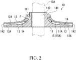
FIG. 2 shows the impeller viewed from the arrow direction of the II-II line inFIG. 1 . -
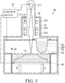
FIG. 3 shows a deposition modeling device used for producing the impeller inFIG. 1 . -
FIG. 4A shows an outline configuration of a device used for polishing a wall surface of a channel in the first embodiment, and especially shows a configuration of the device when a first nozzle member is used. -
FIG. 4B shows another outline configuration of the device used for polishing the wall surface of the channel in the first embodiment, and especially shows a configuration of the device when a second nozzle member is used. -
FIG. 5 is a plan view of the first and second nozzle members used for polishing in the first embodiment, together with the channel of the impeller. -
FIG. 6 is a schematic diagram showing a state that the wall surface of the channel is polished with polishing materials. -
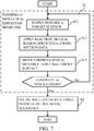
FIG. 7 shows a procedure for producing the impeller according to the first embodiment. -
FIG. 8A is a schematic diagram of a variant of the polishing material. -
FIG. 8B is a schematic diagram for explaining an action of the polishing materials. -
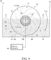
FIG. 9 is a schematic diagram of a channel polishing device according to a second embodiment. - Now, with reference to the accompanying drawings, embodiments of the present invention will be described.
- First, with reference to
FIGS. 1 and2 , a basic configuration of animpeller 10 will be briefly described. - The
impeller 10 is provided in a centrifugal rotating machine such as a centrifugal compressor and assembled to arotating shaft 10A (FIG. 2 ). - The centrifugal compressor typically includes a plurality of
impellers 10 coaxially arranged, and theimpellers 10 successively compress a gas such as air. - As shown in
FIGS. 1 and2 , theimpeller 10 includes ahub 11 having ashaft hole 110 through which therotating shaft 10A is passed, ashroud 12 facing a surface of thehub 11 with a predetermined space from the surface, and a plurality ofblades 13. The space between thehub 11 and theshroud 12 is partitioned by the plurality ofblades 13 to form a plurality of channels 14 (FIG. 1 ). - Each
channel 14 is defined between thehub 11, theshroud 12, andadjacent blades wall 15 that defines thechannel 14 and with which a gas comes into contact is constituted by thehub 11, theshroud 12, and theblades 13. - As shown in
FIG. 2 , eachchannel 14 includes aninlet 141 located on an inner peripheral side of theimpeller 10, and anoutlet 142 located on an outer peripheral side of theimpeller 10. - As shown in
FIGS. 1 and2 , theblades 13 and thechannel 14 between theblades impeller 10. - When the
impeller 10 is rotated in the direction ofarrow 10R (FIG. 1 ) by a drive portion (not shown), the gas in thechannel 14 is accelerated by a centrifugal force. Thus, the gas is sucked from theinlet 141 into thechannel 14, compressed while being flowing through thechannel 14 in a direction of arrow F inFIG. 1 , and discharged from theoutlet 142. - The
impeller 10 is formed by fused deposition modeling using low-alloy steel, stainless steel, or titanium alloy. - The low-alloy steel is, for example, Ni-Cr-Mo steel or Cr-Mo steel. The stainless steel is, for example, precipitation hardening stainless steel, martensitic stainless steel, or two-phase stainless steel.
- To reduce friction loss on the
wall 15 of thechannel 14, asurface 15A of thewall 15 is required to have high smoothness. Thus, thewall 15 of thechannel 14 of the formedimpeller 10 is polished and finished up with a required value of surface roughness. - As shown in
FIGS. 1 and2 , thesurface 15A of thewall 15 of thechannel 14 is constituted by asurface 11A of thehub 11, aninner surface 12A of theshroud 12, afront side surface 13A of theblade 13, and aback side surface 13B of theblade 13 facing thefront side surface 13A. Thefront side surface 13A of theblade 13 protrudes toward theback side surface 13B of theadjacent blade 13. - With reference to
FIG. 3 , adeposition modeling device 30 that can be used to form theimpeller 10 will be described. - The
deposition modeling device 30 forms theimpeller 10 by fused deposition modeling using an electron beam (an electron ray) that is a high-energy heat source. - The
deposition modeling device 30 includes an electronbeam guide path 31 that guides an electron beam EB toward a target surface Tg, achamber 32 in which a workpiece W (the impeller 10) is formed through melting and solidification caused by application of the electron beam EB, and acontrol device 33 that controls components of thedeposition modeling device 30 based on three-dimensional data. - Pressure in the electron
beam guide path 31 and thechamber 32 is reduced to a predetermined degree of vacuum with respect to atmospheric pressure outside thereof. This can reduce oxidation of a use material. - The electron
beam guide path 31 includes an electronbeam generation source 311 that emits the electron beam EB, and a focusingcoil 312 and deflection coils 313 arranged around the electron beam EB. - A target surface Tg to which the electron beam EB is applied is set in an internal space of the
chamber 32. The target surface Tg is a horizontal plane. - The
chamber 32 includes therein ahopper 34 that suppliesmetal powder 201 to the target surface Tg, and a movable table 36 that supports the workpiece W. - In view of residual stress of the workpiece W, a heating device that heats the workpiece W may be provided in the
chamber 32 to control a temperature as necessary. - Next, with reference to
FIGS. 4 and5 ,nozzle members wall 15 of thechannel 14 will be described. - In this embodiment, as shown in
FIGS. 4A and 4B , particulate polishing materials 23 (FIG. 6 ) are sprayed on thesurface 15A of thewall 15 of thechannel 14 fromnozzle holes 21C, 22C (FIG. 5 ) formed in thefirst nozzle member 21 and thesecond nozzle member 22 inserted into thechannel 14. - In this embodiment, mechanical dry polishing without any solution is performed. This is environment-compatible because of no problem in discharge of a solution, and also there is no risk that polishing solution causes corrosion of the
impeller 10 beyond the aim of polishing. Further, there is neither a risk that a hydrogen gas generated by a chemical reaction between metal and polishing solution adheres to the wall surface of the channel to prevent polishing nor a risk that hydrogen is occluded in by the wall of the channel. - The
first nozzle member 21 and thesecond nozzle member 22 are preferably made of tool steel resistant to wear by the polishingmaterials 23. - The
second nozzle member 22 will be described as an example out of thefirst nozzle member 21 and thesecond nozzle member 22. - As shown in
FIGS. 4B and5 , thesecond nozzle member 22 is curved following the shape of thechannel 14 on the side of theoutlet 142, and includes abase end 22A from which the polishingmaterials 23 are supplied and a closedfront end 22B. - Four side walls of the
second nozzle member 22 face thesurface 11A of thehub 11, theinner surface 12A (FIG. 4B ) of theshroud 12, thefront side surface 13A of theblade 13, and theback side surface 13B of theblade 13.FIG. 5 shows aside wall 22D facing theinner surface 12A of theshroud 12. - The four side walls of the
second nozzle member 22 each have a plurality of nozzle holes 22C extending through the side wall in a thickness direction. The nozzle holes 22C are preferably located over a large area in each of the side walls. - As shown in
FIG. 4B , thebase end 22A of thesecond nozzle member 22 is connected to ashot device 25. Theshot device 25 that is a supply source of the polishingmaterials 23 uses compressed air and supplies the polishingmaterials 23 on a high-speed flow of air from thebase end 22A to an inner side (a hollow portion) of thesecond nozzle member 22. The polishingmaterials 23 supplied into thesecond nozzle member 22 are sprayed from each nozzle hole 22C toward thesurface 15A of thewall 15. Then, the polishingmaterials 23 are recovered, and the collected polishingmaterials 23 can be supplied again from theshot device 25. - The
first nozzle member 21 is configured similarly to thesecond nozzle member 22. - As shown in
FIGS. 4A and5 , thefirst nozzle member 21 is curved following the shape of thechannel 14 on the side of theinlet 141, and includes abase end 21A from which the polishingmaterials 23 are supplied by theshot device 25 and a closedfront end 21B. Four side walls of thefirst nozzle member 21 each have a plurality ofnozzle holes 21C extending through the side wall in a thickness direction. - It is preferable that when the
first nozzle member 21 and thesecond nozzle member 22 are inserted into thechannel 14, thefirst nozzle member 21 and thesecond nozzle member 22 generally extend from theinlet 141 to theoutlet 142 of thechannel 14, so that the nozzle holes 21C, 22C are distributed over the almost entire region of thesurface 15A of thewall 15. - The polishing material 23 (a projected material) sprayed from the nozzle holes 21C, 22C in the
first nozzle member 21 and thesecond nozzle member 22 toward thewall 15 of thechannel 14 may be made of, for example, silicon carbide (SiC) or aluminum oxide (Al2O3). - An average particle size of the polishing
material 23 may be set as appropriate in a range of, for example, 50 µm to 100 µm. InFIG. 6 , the polishingmaterial 23 is schematically shown as a spherical particle, but often has an irregular shape caused by crush. However, the polishingmaterial 23 may have a regular shape such as a rectangular parallelepiped, a cube, or a flat shape. - The shape, particle size, spray pressure, specific gravity, hardness, or the like of the polishing
material 23 may be determined in view of target surface roughness, permitted polishing time, or the like. - Now, a method for producing the
impeller 10 will be described. - As shown in
FIG. 7 , theimpeller 10 is produced in a forming step S1 by the fused deposition modeling and a polishing step S2 using the polishingmaterials 23. - First, in the forming step S1, under control by the
control device 33 in thedeposition modeling device 30 shown inFIG. 3 , themetal powder 201 as a material is supplied from thehopper 34 to the target surface Tg (powder supply step S11). Themetal powder 201 is spread on the target surface Tg with a predetermined thickness. A rake arm (not shown) movable in parallel with the target surface Tg may be used as necessary. - Then, the electron beam EB is applied only to a specified region in the target surface Tg based on the cross-section data (electron beam application step S12). At this time, the
control device 33 electromagnetically controls the focusingcoil 312 and thedeflection coil 313, and thus the electron beam EB scans the specific region in the target surface Tg at high speed. Themetal powder 201 is locally melted in a position where the electron beam EB is applied, and solidified after the electron beam EB passes the position. - Any appropriate heating device or an electron beam EB with a low output may be used to preheat the
metal powder 201 before its melting. - After the electron beam EB is applied to the entire specified region in the target surface Tg, through melting and solidification of the
metal powder 201, a layer Ly is formed on the target surface Tg. - Then, the movable table 36 is lowered by a thickness of the layer Ly so as to move and retract (offset) the completed layer Ly from the target surface Tg (moving step S13). The target surface Tg is set to a surface of the layer Ly formed immediately therebefore.
- The above steps S11 to S13 are repeated until stacking of the layers Ly is completed. The stacked layers Ly are tightly bonded to integrally form the
impeller 10. - Each of the plurality of stacked layers Ly has the same thickness as each other. The thickness of each layer Ly may be set as appropriate in a range of, for example, 10 µm to 50 µm.
- The
metal powder 201 supplied around the workpiece W (the impeller 10) or supplied to positions corresponding to insides of thechannel 14 and theshaft hole 110 respectively is not solidified because the electron beam EB is not applied thereto.Such metal powder 201 can be recovered and reused. - The surface roughness Ra of the
wall 15 of thechannel 14 of theimpeller 10 formed by the above is, for example, about 25 µm to 40 µm. - Next, by the polishing step S2, the
wall 15 of thechannel 14 is polished to reach the surface roughness Ra required for thesurface 15A of thewall 15. The required surface roughness Ra is, for example, 0.2 µm. - As shown in
FIGS. 4A and 4B , in the polishing step S2, in a state that thefirst nozzle member 21 and thesecond nozzle member 22 have been inserted into thechannel 14, the polishingmaterials 23 are sprayed toward thesurface 15A of thewall 15 from the nozzle holes 21C, 22C in the first andsecond nozzle members - As shown in
FIG. 4A , thefirst nozzle member 21 is inserted from theinlet 141 into thechannel 14, theshot device 25 is actuated, and thus the polishingmaterials 23 are sprayed together with compressed air from the respect nozzle holes 21C toward thesurface 15A of thewall 15. When the polishingmaterials 23 collide with thesurface 15A of thewall 15 at high speed, thewall 15 is polished, and a surface portion of thewall 15 is subjected to work-hardening and transformation of metal microstructure due to plastic deformation, and further subjected to compression residual stress. The applied residual stress is, for example, 120 MPa to 1000 MPa from data on fine particle peening and ultrasonic cavitation. With respect to the work-hardening of, for example, an aluminum alloy and high-speed tool steel, Vickers hardness is in a range of 40 HV to 700 HV. - The polishing
materials 23 sprayed from therespective nozzle holes 21C can be sucked by a suction device V1 from the side of theoutlet 142 of thechannel 14 and removed from the inside of thechannel 14. - Similarly, as shown in
FIG. 4B , thesecond nozzle member 22 is inserted from theoutlet 142 into thechannel 14, theshot device 25 is actuated, and thus the polishingmaterials 23 are sprayed from the respective nozzle holes 22C toward thesurface 15A of thewall 15. - The polishing
materials 23 and shavings can be sucked by a suction device V2 from the side of theinlet 141 of thechannel 14 and removed from the inside of thechannel 14. - Both the
first nozzle member 21 and thesecond nozzle member 22 may be inserted into thechannel 14 for polishing, or either thefirst nozzle member 21 or thesecond nozzle member 22 may be inserted into one side of thechannel 14 and then replaced by the other nozzle member after polishing of the one side of the wall surface of thechannel 14 is finished. - Even if the
channel 14 of theimpeller 10 has a complicated shape, the first andsecond nozzle members channel 14, and the polishingmaterials 23 are sprayed on thesurface 15A of thewall 15 from the plurality ofnozzle holes 21C, 22C, thereby allowing polishing and smoothing of theentire surface 15A of thewall 15 including an innermost part of thechannel 14. - As described above, the surface roughness Ra of the
wall 15 formed by the fused deposition modeling is in a range of, for example, 25 µm to 40 µm, and is not worse than surface roughness (for example, about 25 µm) of a wall of a channel of an impeller formed by casting or electrical discharge machining. - Thus, by the polishing step S2, the surface roughness Ra can be easily brought to a value or less required for the
wall 15 of thechannel 14 of theimpeller 10, and only a slight amount of surface is removed by polishing, thereby causing little unevenness in polishing (removal is finished before unevenness in polishing occurs). - Depending on the particle size, spray pressure, or the like of the polishing
materials 23 sprayed on thewall 15, the surface roughness of thewall 15 can be brought to a required value simply by performing the polishing step S2 of spraying the polishingmaterials 23 on thewall 15 through thefirst nozzle member 21 and thesecond nozzle member 22, for example, for several seconds to several minutes. - If a wall surface of a channel of an impeller formed by methods other than the fused deposition modeling is polished to reach the required value of the surface roughness, a polishing step takes long time.
- Specifically, according to this embodiment, the
impeller 10 is formed by the fused deposition modeling, and theparticulate polishing materials 23 are sprayed toward thewall 15 of thechannel 14 of theimpeller 10. Thereby, it is possible to improve efficiency of the entire production including forming of theimpeller 10 and polishing to a predetermined surface roughness as compared to a case where a wall surface of a channel of an impeller formed by methods other than the fused deposition modeling is polished. - Further, a product formed by deposition modeling generally has metal microstructure and strength inferior to those of a product obtained by machining such as rolling, casting, or forging. However, according to this embodiment, work-hardening, transformation of metal microstructure, and application of compression residual stress caused by spraying the
particulate polishing materials 23 can improve fatigue strength, resistance to wear, and resistance to stress corrosion crack. - Specifically, according to this embodiment including the forming step S1 by the fused deposition modeling and the polishing step S2 using the
particulate polishing materials 23, surface roughness that can be achieved in a product formed by the fused deposition modeling can be made use of in the polishing step S2 to improve production efficiency, and mechanical properties of the product formed by the fused deposition modeling can be improved in the polishing step S2 to ensure reliability of theimpeller 10. - This can advantageously provide an
impeller 10 with high performance and reliability at low cost. - In this embodiment, a laser beam may be used instead of the electron beam EB as the heat source for melting the
metal powder 201. In that case, thedeposition modeling device 30 may include a laser oscillator instead of the electronbeam generation source 311. - If there is a possibility that unevenness in polishing occurs in the
surface 15A of thewall 15 on which the polishingmaterials 23 have been sprayed because of conditions such as the specific gravity, hardness, particle size, and spray pressure of the polishingmaterials 23, the material of theimpeller 10, and the like, it is advantageous that thefirst nozzle member 21 and thesecond nozzle member 22 are moved in thechannel 14. - Between the four side walls of the
first nozzle member 21 and thesurface 15A of thewall 15 facing the side walls, there is a space that allows thefirst nozzle member 21 to be moved in a flow direction of thechannel 14 and a width direction of the channel 14 (a circumferential direction of the impeller 10). The same applies to thesecond nozzle member 22. - Thus, the polishing
materials 23 can be sprayed from the nozzle holes 21C, 22C to polish thewall 15 while thefirst nozzle member 21 and thesecond nozzle member 22 are being moved in thechannel 14. - The
first nozzle member 21 and thesecond nozzle member 22 may be moved, manually or using a drive device, in thechannel 14 in a predetermined direction by a predetermined stroke. The first andsecond nozzle members channel 14. During the time from start to end of the polishing step S2, the first andsecond nozzle members - As the first and
second nozzle members materials 23 sprayed from the nozzle holes 21C, 22C collide with thesurface 15A of thewall 15 are also changed. This can reduce unevenness in polishing, and allows polishing to be finished in a shorter time. - Only one of the first and
second nozzle members surface 15A in which there is a possibility that unevenness in polishing occurs. - The number, opening diameters, density, layout, and the like of the nozzle holes 21C, 22C may be determined in view of spray pressure and the like of the polishing
materials 23 for each partial portion of the respective first andsecond nozzle members - If spray pressure at the front ends 21B, 22B farther from the
shot device 25 is lower than that at the base ends 21A, 22A closer to theshot device 25 in the first andsecond nozzle member - In the polishing step S2 of this embodiment, an
elastic polishing material 24 inFIG. 8A may be used. Theelastic polishing material 24 includes aparticulate core material 241 having elasticity and adhesion andabrasive grains 242 stacked on a surface of thecore material 241 in a radial direction of thecore material 241 to form a plurality of layers. - The
core material 241 can be made of a polymer material having low elastic modulus and adhesion. For example, a polyrotaxane compound is favorable. - In
FIG. 8A , thecore material 241 is schematically shown as a spherical particle, but often has an irregular shape caused by crush. However, thecore material 241 may have a regular shape such as a rectangular parallelepiped, a cube, or a flat shape. - An average particle size of the
core material 241 may be set as appropriate in a range of, for example, 0.05 mm to 3.0 mm. - The
abrasive grains 242 may be made of, for example, diamond, boron carbide (B4C), silicon carbide, alumina, tungsten carbide, zirconia, zircon, garnet, quartz, glass, or the like. Theabrasive grains 242 made of different materials may be mixed and provided on the surface of thecore material 241. - An average particle size of each
abrasive grain 242 may be set as appropriate in a range of, for example, 0.1 µm to 12 µm. - An average particle size of the
elastic polishing material 24 as a whole including thecore material 241 and layers of theabrasive grains 242 may be set as appropriate in a range of, for example, 0.05 mm to 3.0 mm. - After the
abrasive grains 242 are adhered to the surface of thecore material 241, a pressing force is applied by pushing, hitting, or collision to stabilize theabrasive grains 242 on the surface of thecore material 241. Theabrasive grains 242 are again adhered to thecore material 241 exposed between theabrasive grains 242 by the application of the pressing force, and then the pressing force is applied. By repeating this process, layers of theabrasive grains 242 are stacked on the surface of thecore material 241, and finally, the entire surface of thecore material 241 is tightly covered with theabrasive grains 242. Specifically, thecore material 241 is confined inside theabrasive grains 242. Theabrasive grains 242 in each layer is supported on the surface of thecore material 241 by adhesion of thecore material 241. - The number of layers of the
abrasive grains 242 or the thickness of each layer may be determined so that theelastic polishing material 24 keeps elasticity as a whole. - If the
shot device 25 is actuated with the first andsecond nozzle members channel 14, as shown inFIG. 8B , theelastic polishing materials 24 are sprayed together with compressed air from therespective nozzle holes 21C, 22C toward thesurface 15A of thewall 15. At this time, eachelastic polishing material 24 is easily deformed to be flat by collision with thewall 15, and thus has a large contact area with thewall 15. Also, in that state, theelastic polishing material 24 polishes thewall 15 while sliding along thewall 15. - With the
elastic polishing material 24, a load in the collision is widely dispersed by elastic deformation, and a contact region is displaced by sliding. This allows a larger region on the wall surface to be evenly polished, and further, polished more smoothly in a shorter time. - Next, a production of an
impeller 10 according to a second embodiment of the present invention will be described. - The second embodiment is different from the first embodiment in a method of polishing a
wall 15 of achannel 14 of animpeller 10 formed by fused deposition modeling, and the same as the first embodiment in other matters. - In the second embodiment, as shown in
FIG. 9 , a polishingmaterial pool 40 that stores polishingmaterials 41 and adrive device 45 are used to polish thewall 15 of thechannel 14 of theimpeller 10. - The polishing
material pool 40 includes theparticulate polishing materials 41, and acontainer 42 that can house the polishingmaterials 41 and theimpeller 10. - The polishing
materials 41 may be the same as the polishingmaterials 23 described in the first embodiment. It is enough that the polishingmaterials 41 fills, for example, half of the volume of thecontainer 42. An appropriate amount of the polishingmaterials 41 in thecontainer 42 may be determined so as to be enough to sufficiently polish thewall 15 of thechannel 14 and not to be excessive for resistance of theimpeller 10 in the polishingmaterial pool 40. - The
impeller 10 is disposed in thecontainer 42 so that an axis thereof extends along a horizontal direction. As described later, the axis of theimpeller 10 may be inclined to the horizontal direction as long as the polishingmaterials 41 scooped up byblades 13 can flow down due to self-weight. - The
drive device 45 supports theimpeller 10 disposed in thecontainer 42 with a jig (not shown) and ashaft 451, and rotates theimpeller 10 around the axis. A rotating direction at this time is opposite to a rotating direction of theimpeller 10 being used after incorporated into a centrifugal rotating machine (see arrow R inFIG. 9 ). - The
drive device 45 rotates theimpeller 10 at a sufficiently lower speed than a rotation speed of theimpeller 10 being used after incorporated into the centrifugal rotating machine and used. - After the
impeller 10 is formed by fused deposition modeling, a polishing step is performed using the polishingmaterial pool 40 and thedrive device 45. - In the polishing step, the
impeller 10 is housed together with the polishingmaterials 41 in thecontainer 42 of the polishingmaterial pool 40. Then, thedrive device 45 rotates theimpeller 10 around the axis in the direction of arrow R. - As the
impeller 10 is rotated in thecontainer 42, the polishingmaterials 41 gradually enter thechannel 14 from anoutlet 142 to fill thechannel 14. Then, while being scooped up by back side surfaces 13B of theblades 13, the polishingmaterials 41 are forced to flow toward aninlet 141 due to self-weight (see arrow A inFIG. 9 ), and discharged from theinlet 141 into the polishingmaterial pool 40. While this process is repeated, the polishingmaterials 41 in thecontainer 42 are circulated between the inside and outside of thechannel 14. - As described above, while the polishing
materials 41 are forced to flow through thechannel 14 toward theinlet 141, the polishingmaterials 41 rub and polish thewall 15 of thechannel 14. - Even if the
channel 14 has a complicated shape, an aggregate of the polishingmaterials 41 rub thewall 15 of thechannel 14, thereby allowing polishing and smoothing of the entire surface of thewall 15. - Also by the polishing method of the second embodiment, the surface roughness of the
wall 15 formed by the fused deposition modeling can be easily brought to the required value or less. Further, only a slight amount of surface is removed by polishing, thereby causing little unevenness in polishing - In the first and second embodiments, after the
impeller 10 is formed by fused deposition modeling, an erosion-resistant coating may be applied to the surface of thewall 15 of thechannel 14. Such a coating may be formed by chemical or physical vapor deposition, using, for example, WC-based composite (cermet) mainly containing tungsten carbide (WC), Cr3C2-based composite, alumina-titania (AlO3-TiO2), chromic oxide ceramics (Cr2O3), or the like. Such a coating can prevent wear, thickness reduction, or corrosion (particle erosion) of the wall surface of the channel caused by collision of waterdrops, dust, foreign matters, and the like included in a fluid. - As described above, since the surface roughness of the
wall 15 of thechannel 14 of theimpeller 10 at the moment after fused deposition modeling is in a range of, for example, about 25 µm to 40 µm, minute irregularities on the surface of the base material of theimpeller 10 and the erosion-resistant coating are firmly joined by an anchor effect. - Since the surface roughness of the base material of the
impeller 10 at the moment after the fused deposition modeling is in a range of, for example, about 25 µm to 40 µm, surface roughness of the erosion-resistant coating that covers the surface of the base material is low, and the range is, for example, about 10 nm to 800 nm. Thus, the surface roughness of the coating can be easily brought to the surface roughness required for thewall 15 of thechannel 14. Specifically, between the forming step by the fused deposition modeling described above and the polishing step by the method described in the first or second embodiment, a step of applying the erosion-resistant coating may be provided. - Other than the above, the configurations in the embodiments may be chosen or modified to other configurations without departing from the gist of the present invention.
-
- 10
- impeller
- 10A
- rotating shaft
- 10R
- arrow
- 11
- hub
- 11A
- surface
- 12
- shroud
- 12A
- inner surface
- 13
- blade
- 13A
- front side surface
- 13B
- back side surface
- 14
- channel(s)
- 15
- wall
- 15A
- surface
- 21
- first nozzle member
- 21A
- base end
- 21B
- front end
- 21C
- nozzle hole(s)
- 22
- second nozzle member
- 22A
- base end
- 22B
- front end
- 22C
- nozzle hole(s)
- 22D
- side wall
- 23
- polishing material(s)
- 24
- elastic polishing material(s)
- 25
- shot device (supply source)
- 30
- deposition modeling device
- 31
- electron beam guide path
- 32
- chamber
- 33
- control device
- 34
- hopper
- 36
- movable table
- 40
- polishing material pool
- 41
- polishing material(s)
- 42
- container
- 45
- drive device
- 110
- shaft hole
- 141
- inlet
- 142
- outlet
- 201
- metal powder
- 241
- core material
- 242
- abrasive grain(s)
- 311
- electron beam generation source
- 312
- focusing coil
- 313
- deflection coil(s)
- A
- arrow
- EB
- electron beam
- F
- arrow
- Ly
- layer(s)
- R
- arrow
- S1
- forming step
- S11
- powder supply step
- S12
- electron beam application step
- S13
- moving step
- S2
- polishing step
- Tg
- target surface
- V1
- suction device
- V2
- suction device
- W
- workpiece
Claims (8)
- A method for producing an impeller, comprising:a forming step of forming the impeller by fused deposition modeling; anda polishing step of polishing a wall that defines a channel of the impeller using particulate polishing materials,wherein the particulate polishing materials are sprayed on the wall of the channel or the wall of the channel is rubbed with the particulate polishing materials in the polishing step.
- The method according to claim 1, wherein the wall of the channel is polished to reach surface roughness Ra of 0.2 µm or less in the polishing step.
- The method according to claim 1 or 2, wherein surface roughness Ra of a not yet polished wall of the impeller formed in the forming step is in a range of 25 µm to 40 µm.
- The method according to any one of claims 1 to 3, wherein the impeller is formed by successively stacking layers in the forming step, each of the layers being formed through melting and solidification of a use material and having a thickness of 100 µm to 1000 µm.
- The method according to any one of claims 1 to 4, wherein, in the polishing step, in a state that a nozzle member to which the particulate polishing materials are supplied from a supply source of the particulate polishing materials has been inserted into the channel, the particulate polishing materials are sprayed toward the wall from a plurality of holes formed in the nozzle member.
- The method according to claim 5, wherein, in the polishing step, the particulate polishing materials are sprayed toward the wall from the holes while the nozzle member is being moved in the channel.
- The method according to claim 5 or 6, wherein elastic polishing materials are used as the particulate polishing materials, each of the elastic polishing materials including a core material having elasticity and adhesion and abrasive grains covering the core material.
- The method according to any one of claims 1 to 4, wherein, in the polishing step, by rotating the impeller disposed in a polishing material pool that pools the particulate polishing materials in an opposite direction of a rotating direction in use, the particulate polishing materials having entered the channel from an outlet of the channel rubs the wall while being forced to flow toward an inlet of the channel due to self-weight.
Applications Claiming Priority (2)
| Application Number | Priority Date | Filing Date | Title |
|---|---|---|---|
| JP2016065616A JP2017180178A (en) | 2016-03-29 | 2016-03-29 | Impeller manufacturing method by hot melt additive manufacturing and mechanical polishing |
| PCT/JP2017/012989 WO2017170730A1 (en) | 2016-03-29 | 2017-03-29 | Impeller production method by fused deposition modeling and mechanical polishing |
Publications (3)
| Publication Number | Publication Date |
|---|---|
| EP3438462A1 true EP3438462A1 (en) | 2019-02-06 |
| EP3438462A4 EP3438462A4 (en) | 2019-05-01 |
| EP3438462B1 EP3438462B1 (en) | 2020-04-29 |
Family
ID=59965700
Family Applications (1)
| Application Number | Title | Priority Date | Filing Date |
|---|---|---|---|
| EP17775264.9A Not-in-force EP3438462B1 (en) | 2016-03-29 | 2017-03-29 | Impeller production method by fused deposition modeling and mechanical polishing |
Country Status (4)
| Country | Link |
|---|---|
| US (1) | US20190134779A1 (en) |
| EP (1) | EP3438462B1 (en) |
| JP (1) | JP2017180178A (en) |
| WO (1) | WO2017170730A1 (en) |
Cited By (2)
| Publication number | Priority date | Publication date | Assignee | Title |
|---|---|---|---|---|
| EP3520964A4 (en) * | 2016-09-28 | 2020-03-18 | Sintokogio, Ltd. | SURFACE TREATMENT METHOD FOR SOLID METAL STRUCTURES |
| WO2024041754A1 (en) * | 2022-08-24 | 2024-02-29 | Cryostar Sas | Method for manufacturing an impeller and impeller |
Families Citing this family (9)
| Publication number | Priority date | Publication date | Assignee | Title |
|---|---|---|---|---|
| US11333162B2 (en) * | 2017-02-24 | 2022-05-17 | Mitsubishi Heavy Industries Compressor Corporation | Impeller manufacturing method and impeller flow path elongation jig |
| CN107717687B (en) * | 2017-10-19 | 2023-08-01 | 浙江工业大学 | Gas-liquid-solid three-phase abrasive particle flow polishing tool based on cavitation effect |
| US10710212B2 (en) * | 2017-10-30 | 2020-07-14 | Delavan Inc. | Methods, systems, and apparatuses for improving surface finish of additively manufactured parts |
| JP2019123053A (en) | 2018-01-18 | 2019-07-25 | 三菱重工コンプレッサ株式会社 | Narrow part polishing jig, manufacturing method of the same, polishing method, and manufacturing method of impeller |
| US11364587B2 (en) * | 2018-04-19 | 2022-06-21 | Raytheon Technologies Corporation | Flow directors and shields for abrasive flow machining of internal passages |
| US11376661B2 (en) * | 2019-06-06 | 2022-07-05 | Raytheon Technologies Corporation | Apparatus and methods for improvement of surface geometries of internal channels of additively manufactured components |
| KR20240160107A (en) | 2022-03-04 | 2024-11-08 | 크라이오스타 에스아에스 | Method of manufacturing an impeller |
| CN115741445B (en) * | 2022-11-21 | 2023-08-01 | 滁州市成业机械制造股份有限公司 | Processing equipment for multistage centrifugal pump impeller |
| CN117600774A (en) * | 2023-11-10 | 2024-02-27 | 江苏集萃精密制造研究院有限公司 | An integral manufacturing method for special processing of integrated diffuser inter-blade channels |
Family Cites Families (9)
| Publication number | Priority date | Publication date | Assignee | Title |
|---|---|---|---|---|
| ES2178495T3 (en) * | 1998-11-14 | 2002-12-16 | Mtu Aero Engines Gmbh | PRECISION MECHANIZATION SYSTEM OF ROTARY SIMETRIC COMPONENT PARTS. |
| US20050127205A1 (en) * | 2002-07-04 | 2005-06-16 | Siemens Aktiengesellschaft | Method and device for the hydro-erosive rounding of an edge of a component |
| US8613641B2 (en) * | 2008-10-22 | 2013-12-24 | Pratt & Whitney Canada Corp. | Channel inlet edge deburring for gas diffuser cases |
| JP2013104321A (en) * | 2011-11-11 | 2013-05-30 | Mitsubishi Heavy Ind Ltd | Method for manufacturing impeller of centrifugal rotating machine |
| ITFI20120035A1 (en) * | 2012-02-23 | 2013-08-24 | Nuovo Pignone Srl | "IMPELLER PRODUCTION FOR TURBO-MACHINES" |
| JP2014009733A (en) * | 2012-06-28 | 2014-01-20 | Nsk Ltd | Roller bearing |
| JP2014094433A (en) * | 2012-11-09 | 2014-05-22 | Mitsubishi Heavy Ind Ltd | Manufacturing method of impeller for centrifugal rotating machine |
| US9505058B2 (en) * | 2014-05-16 | 2016-11-29 | Xerox Corporation | Stabilized metallic nanoparticles for 3D printing |
| DE102014012480B4 (en) * | 2014-08-27 | 2016-06-09 | Rosswag Gmbh | Manufacturing process for a blading of a turbomachine, blading a turbomachine and impeller |
-
2016
- 2016-03-29 JP JP2016065616A patent/JP2017180178A/en active Pending
-
2017
- 2017-03-29 US US16/089,852 patent/US20190134779A1/en not_active Abandoned
- 2017-03-29 WO PCT/JP2017/012989 patent/WO2017170730A1/en not_active Ceased
- 2017-03-29 EP EP17775264.9A patent/EP3438462B1/en not_active Not-in-force
Cited By (2)
| Publication number | Priority date | Publication date | Assignee | Title |
|---|---|---|---|---|
| EP3520964A4 (en) * | 2016-09-28 | 2020-03-18 | Sintokogio, Ltd. | SURFACE TREATMENT METHOD FOR SOLID METAL STRUCTURES |
| WO2024041754A1 (en) * | 2022-08-24 | 2024-02-29 | Cryostar Sas | Method for manufacturing an impeller and impeller |
Also Published As
| Publication number | Publication date |
|---|---|
| EP3438462A4 (en) | 2019-05-01 |
| WO2017170730A1 (en) | 2017-10-05 |
| EP3438462B1 (en) | 2020-04-29 |
| US20190134779A1 (en) | 2019-05-09 |
| JP2017180178A (en) | 2017-10-05 |
Similar Documents
| Publication | Publication Date | Title |
|---|---|---|
| EP3438462B1 (en) | Impeller production method by fused deposition modeling and mechanical polishing | |
| US9835163B2 (en) | Impeller assembly of fluid rotary machine and manufacturing method thereof | |
| EP0968316B1 (en) | Method of treating metal components | |
| CN102123828B (en) | Ultrasonic Shot Peening of Turbine Components | |
| US20090162207A1 (en) | Method For The Manufacture Of An Erosion Protection Layer And A Component With Said Erosion Protection Layer | |
| JP2005271201A (en) | Device and method for improving surface of workpiece | |
| KR20190024828A (en) | Method and apparatus for fluid cavitation abrasive surface finishing | |
| JP2002275658A (en) | Enhanced surface preparation process for application of ceramic coating | |
| US7264538B2 (en) | Method of removing a coating | |
| CN108972350A (en) | The ball blasting method of turbine engine components | |
| JP4131371B2 (en) | Cylinder block manufacturing method | |
| CA2589964A1 (en) | Method for surface blasting cavities, particularly cavities in gas turbines | |
| JP2017180177A (en) | Impeller manufacturing method and impeller by hot melt additive manufacturing using different materials | |
| JP6216570B2 (en) | Component with cooling channel and manufacturing method | |
| JP6254820B2 (en) | Component with microcooled patterning coating layer and method of manufacturing | |
| JP2014094433A (en) | Manufacturing method of impeller for centrifugal rotating machine | |
| WO2017170731A1 (en) | Impeller manufacturing method | |
| CN111660206B (en) | Surface treatment method for DLC coated member | |
| JP6693827B2 (en) | Method of manufacturing integrated impeller | |
| Gavcar et al. | Mechanical post-processing techniques for metal additive manufacturing | |
| Feldmann et al. | Mechanical surface treatment technologies for improving HCF strength and surface roughness of blisk-rotors | |
| EP3838486B1 (en) | Abrasive coating including metal matrix and ceramic particles | |
| JP4252556B2 (en) | How to remove hard coating | |
| Kienzler et al. | Burr minimization and removal by micro milling strategies or micro peening processes | |
| JP2540672B2 (en) | High pressure injection nozzle |
Legal Events
| Date | Code | Title | Description |
|---|---|---|---|
| STAA | Information on the status of an ep patent application or granted ep patent |
Free format text: STATUS: THE INTERNATIONAL PUBLICATION HAS BEEN MADE |
|
| PUAI | Public reference made under article 153(3) epc to a published international application that has entered the european phase |
Free format text: ORIGINAL CODE: 0009012 |
|
| STAA | Information on the status of an ep patent application or granted ep patent |
Free format text: STATUS: REQUEST FOR EXAMINATION WAS MADE |
|
| 17P | Request for examination filed |
Effective date: 20180926 |
|
| AK | Designated contracting states |
Kind code of ref document: A1 Designated state(s): AL AT BE BG CH CY CZ DE DK EE ES FI FR GB GR HR HU IE IS IT LI LT LU LV MC MK MT NL NO PL PT RO RS SE SI SK SM TR |
|
| AX | Request for extension of the european patent |
Extension state: BA ME |
|
| A4 | Supplementary search report drawn up and despatched |
Effective date: 20190403 |
|
| RIC1 | Information provided on ipc code assigned before grant |
Ipc: F04D 29/28 20060101ALI20190328BHEP Ipc: B24C 3/32 20060101ALI20190328BHEP Ipc: F04D 29/62 20060101ALI20190328BHEP Ipc: F04D 29/30 20060101AFI20190328BHEP Ipc: B24C 1/08 20060101ALI20190328BHEP Ipc: F04D 29/02 20060101ALI20190328BHEP |
|
| DAV | Request for validation of the european patent (deleted) | ||
| DAX | Request for extension of the european patent (deleted) | ||
| GRAP | Despatch of communication of intention to grant a patent |
Free format text: ORIGINAL CODE: EPIDOSNIGR1 |
|
| STAA | Information on the status of an ep patent application or granted ep patent |
Free format text: STATUS: GRANT OF PATENT IS INTENDED |
|
| INTG | Intention to grant announced |
Effective date: 20191029 |
|
| GRAS | Grant fee paid |
Free format text: ORIGINAL CODE: EPIDOSNIGR3 |
|
| GRAA | (expected) grant |
Free format text: ORIGINAL CODE: 0009210 |
|
| STAA | Information on the status of an ep patent application or granted ep patent |
Free format text: STATUS: THE PATENT HAS BEEN GRANTED |
|
| AK | Designated contracting states |
Kind code of ref document: B1 Designated state(s): AL AT BE BG CH CY CZ DE DK EE ES FI FR GB GR HR HU IE IS IT LI LT LU LV MC MK MT NL NO PL PT RO RS SE SI SK SM TR |
|
| REG | Reference to a national code |
Ref country code: GB Ref legal event code: FG4D |
|
| REG | Reference to a national code |
Ref country code: CH Ref legal event code: EP |
|
| REG | Reference to a national code |
Ref country code: AT Ref legal event code: REF Ref document number: 1263733 Country of ref document: AT Kind code of ref document: T Effective date: 20200515 |
|
| REG | Reference to a national code |
Ref country code: DE Ref legal event code: R096 Ref document number: 602017015836 Country of ref document: DE |
|
| REG | Reference to a national code |
Ref country code: IE Ref legal event code: FG4D |
|
| REG | Reference to a national code |
Ref country code: NL Ref legal event code: MP Effective date: 20200429 |
|
| REG | Reference to a national code |
Ref country code: LT Ref legal event code: MG4D |
|
| PG25 | Lapsed in a contracting state [announced via postgrant information from national office to epo] |
Ref country code: IS Free format text: LAPSE BECAUSE OF FAILURE TO SUBMIT A TRANSLATION OF THE DESCRIPTION OR TO PAY THE FEE WITHIN THE PRESCRIBED TIME-LIMIT Effective date: 20200829 Ref country code: PT Free format text: LAPSE BECAUSE OF FAILURE TO SUBMIT A TRANSLATION OF THE DESCRIPTION OR TO PAY THE FEE WITHIN THE PRESCRIBED TIME-LIMIT Effective date: 20200831 Ref country code: GR Free format text: LAPSE BECAUSE OF FAILURE TO SUBMIT A TRANSLATION OF THE DESCRIPTION OR TO PAY THE FEE WITHIN THE PRESCRIBED TIME-LIMIT Effective date: 20200730 Ref country code: NO Free format text: LAPSE BECAUSE OF FAILURE TO SUBMIT A TRANSLATION OF THE DESCRIPTION OR TO PAY THE FEE WITHIN THE PRESCRIBED TIME-LIMIT Effective date: 20200729 Ref country code: FI Free format text: LAPSE BECAUSE OF FAILURE TO SUBMIT A TRANSLATION OF THE DESCRIPTION OR TO PAY THE FEE WITHIN THE PRESCRIBED TIME-LIMIT Effective date: 20200429 Ref country code: SE Free format text: LAPSE BECAUSE OF FAILURE TO SUBMIT A TRANSLATION OF THE DESCRIPTION OR TO PAY THE FEE WITHIN THE PRESCRIBED TIME-LIMIT Effective date: 20200429 Ref country code: LT Free format text: LAPSE BECAUSE OF FAILURE TO SUBMIT A TRANSLATION OF THE DESCRIPTION OR TO PAY THE FEE WITHIN THE PRESCRIBED TIME-LIMIT Effective date: 20200429 |
|
| REG | Reference to a national code |
Ref country code: AT Ref legal event code: MK05 Ref document number: 1263733 Country of ref document: AT Kind code of ref document: T Effective date: 20200429 |
|
| PG25 | Lapsed in a contracting state [announced via postgrant information from national office to epo] |
Ref country code: BG Free format text: LAPSE BECAUSE OF FAILURE TO SUBMIT A TRANSLATION OF THE DESCRIPTION OR TO PAY THE FEE WITHIN THE PRESCRIBED TIME-LIMIT Effective date: 20200729 Ref country code: RS Free format text: LAPSE BECAUSE OF FAILURE TO SUBMIT A TRANSLATION OF THE DESCRIPTION OR TO PAY THE FEE WITHIN THE PRESCRIBED TIME-LIMIT Effective date: 20200429 Ref country code: LV Free format text: LAPSE BECAUSE OF FAILURE TO SUBMIT A TRANSLATION OF THE DESCRIPTION OR TO PAY THE FEE WITHIN THE PRESCRIBED TIME-LIMIT Effective date: 20200429 Ref country code: HR Free format text: LAPSE BECAUSE OF FAILURE TO SUBMIT A TRANSLATION OF THE DESCRIPTION OR TO PAY THE FEE WITHIN THE PRESCRIBED TIME-LIMIT Effective date: 20200429 |
|
| PG25 | Lapsed in a contracting state [announced via postgrant information from national office to epo] |
Ref country code: NL Free format text: LAPSE BECAUSE OF FAILURE TO SUBMIT A TRANSLATION OF THE DESCRIPTION OR TO PAY THE FEE WITHIN THE PRESCRIBED TIME-LIMIT Effective date: 20200429 Ref country code: AL Free format text: LAPSE BECAUSE OF FAILURE TO SUBMIT A TRANSLATION OF THE DESCRIPTION OR TO PAY THE FEE WITHIN THE PRESCRIBED TIME-LIMIT Effective date: 20200429 |
|
| PG25 | Lapsed in a contracting state [announced via postgrant information from national office to epo] |
Ref country code: AT Free format text: LAPSE BECAUSE OF FAILURE TO SUBMIT A TRANSLATION OF THE DESCRIPTION OR TO PAY THE FEE WITHIN THE PRESCRIBED TIME-LIMIT Effective date: 20200429 Ref country code: SM Free format text: LAPSE BECAUSE OF FAILURE TO SUBMIT A TRANSLATION OF THE DESCRIPTION OR TO PAY THE FEE WITHIN THE PRESCRIBED TIME-LIMIT Effective date: 20200429 Ref country code: EE Free format text: LAPSE BECAUSE OF FAILURE TO SUBMIT A TRANSLATION OF THE DESCRIPTION OR TO PAY THE FEE WITHIN THE PRESCRIBED TIME-LIMIT Effective date: 20200429 Ref country code: DK Free format text: LAPSE BECAUSE OF FAILURE TO SUBMIT A TRANSLATION OF THE DESCRIPTION OR TO PAY THE FEE WITHIN THE PRESCRIBED TIME-LIMIT Effective date: 20200429 Ref country code: RO Free format text: LAPSE BECAUSE OF FAILURE TO SUBMIT A TRANSLATION OF THE DESCRIPTION OR TO PAY THE FEE WITHIN THE PRESCRIBED TIME-LIMIT Effective date: 20200429 Ref country code: CZ Free format text: LAPSE BECAUSE OF FAILURE TO SUBMIT A TRANSLATION OF THE DESCRIPTION OR TO PAY THE FEE WITHIN THE PRESCRIBED TIME-LIMIT Effective date: 20200429 Ref country code: ES Free format text: LAPSE BECAUSE OF FAILURE TO SUBMIT A TRANSLATION OF THE DESCRIPTION OR TO PAY THE FEE WITHIN THE PRESCRIBED TIME-LIMIT Effective date: 20200429 |
|
| REG | Reference to a national code |
Ref country code: DE Ref legal event code: R097 Ref document number: 602017015836 Country of ref document: DE |
|
| PG25 | Lapsed in a contracting state [announced via postgrant information from national office to epo] |
Ref country code: PL Free format text: LAPSE BECAUSE OF FAILURE TO SUBMIT A TRANSLATION OF THE DESCRIPTION OR TO PAY THE FEE WITHIN THE PRESCRIBED TIME-LIMIT Effective date: 20200429 Ref country code: SK Free format text: LAPSE BECAUSE OF FAILURE TO SUBMIT A TRANSLATION OF THE DESCRIPTION OR TO PAY THE FEE WITHIN THE PRESCRIBED TIME-LIMIT Effective date: 20200429 |
|
| PLBE | No opposition filed within time limit |
Free format text: ORIGINAL CODE: 0009261 |
|
| STAA | Information on the status of an ep patent application or granted ep patent |
Free format text: STATUS: NO OPPOSITION FILED WITHIN TIME LIMIT |
|
| 26N | No opposition filed |
Effective date: 20210201 |
|
| PG25 | Lapsed in a contracting state [announced via postgrant information from national office to epo] |
Ref country code: SI Free format text: LAPSE BECAUSE OF FAILURE TO SUBMIT A TRANSLATION OF THE DESCRIPTION OR TO PAY THE FEE WITHIN THE PRESCRIBED TIME-LIMIT Effective date: 20200429 |
|
| PG25 | Lapsed in a contracting state [announced via postgrant information from national office to epo] |
Ref country code: MC Free format text: LAPSE BECAUSE OF FAILURE TO SUBMIT A TRANSLATION OF THE DESCRIPTION OR TO PAY THE FEE WITHIN THE PRESCRIBED TIME-LIMIT Effective date: 20200429 |
|
| REG | Reference to a national code |
Ref country code: CH Ref legal event code: PL |
|
| GBPC | Gb: european patent ceased through non-payment of renewal fee |
Effective date: 20210329 |
|
| REG | Reference to a national code |
Ref country code: BE Ref legal event code: MM Effective date: 20210331 |
|
| PG25 | Lapsed in a contracting state [announced via postgrant information from national office to epo] |
Ref country code: GB Free format text: LAPSE BECAUSE OF NON-PAYMENT OF DUE FEES Effective date: 20210329 Ref country code: FR Free format text: LAPSE BECAUSE OF NON-PAYMENT OF DUE FEES Effective date: 20210331 Ref country code: IE Free format text: LAPSE BECAUSE OF NON-PAYMENT OF DUE FEES Effective date: 20210329 Ref country code: LI Free format text: LAPSE BECAUSE OF NON-PAYMENT OF DUE FEES Effective date: 20210331 Ref country code: LU Free format text: LAPSE BECAUSE OF NON-PAYMENT OF DUE FEES Effective date: 20210329 Ref country code: CH Free format text: LAPSE BECAUSE OF NON-PAYMENT OF DUE FEES Effective date: 20210331 |
|
| PG25 | Lapsed in a contracting state [announced via postgrant information from national office to epo] |
Ref country code: BE Free format text: LAPSE BECAUSE OF NON-PAYMENT OF DUE FEES Effective date: 20210331 |
|
| PG25 | Lapsed in a contracting state [announced via postgrant information from national office to epo] |
Ref country code: CY Free format text: LAPSE BECAUSE OF FAILURE TO SUBMIT A TRANSLATION OF THE DESCRIPTION OR TO PAY THE FEE WITHIN THE PRESCRIBED TIME-LIMIT Effective date: 20200429 |
|
| PG25 | Lapsed in a contracting state [announced via postgrant information from national office to epo] |
Ref country code: HU Free format text: LAPSE BECAUSE OF FAILURE TO SUBMIT A TRANSLATION OF THE DESCRIPTION OR TO PAY THE FEE WITHIN THE PRESCRIBED TIME-LIMIT; INVALID AB INITIO Effective date: 20170329 |
|
| PG25 | Lapsed in a contracting state [announced via postgrant information from national office to epo] |
Ref country code: MK Free format text: LAPSE BECAUSE OF FAILURE TO SUBMIT A TRANSLATION OF THE DESCRIPTION OR TO PAY THE FEE WITHIN THE PRESCRIBED TIME-LIMIT Effective date: 20200429 |
|
| PGFP | Annual fee paid to national office [announced via postgrant information from national office to epo] |
Ref country code: DE Payment date: 20240130 Year of fee payment: 8 |
|
| PGFP | Annual fee paid to national office [announced via postgrant information from national office to epo] |
Ref country code: IT Payment date: 20240212 Year of fee payment: 8 |
|
| PG25 | Lapsed in a contracting state [announced via postgrant information from national office to epo] |
Ref country code: TR Free format text: LAPSE BECAUSE OF FAILURE TO SUBMIT A TRANSLATION OF THE DESCRIPTION OR TO PAY THE FEE WITHIN THE PRESCRIBED TIME-LIMIT Effective date: 20200429 |
|
| PG25 | Lapsed in a contracting state [announced via postgrant information from national office to epo] |
Ref country code: MT Free format text: LAPSE BECAUSE OF FAILURE TO SUBMIT A TRANSLATION OF THE DESCRIPTION OR TO PAY THE FEE WITHIN THE PRESCRIBED TIME-LIMIT Effective date: 20200429 |
|
| REG | Reference to a national code |
Ref country code: DE Ref legal event code: R119 Ref document number: 602017015836 Country of ref document: DE |
|
| PG25 | Lapsed in a contracting state [announced via postgrant information from national office to epo] |
Ref country code: DE Free format text: LAPSE BECAUSE OF NON-PAYMENT OF DUE FEES Effective date: 20251001 |
|
| PG25 | Lapsed in a contracting state [announced via postgrant information from national office to epo] |
Ref country code: IT Free format text: LAPSE BECAUSE OF NON-PAYMENT OF DUE FEES Effective date: 20250329 |