EP3438461A1 - Electric fan and electric vacuum cleaner equipped with same - Google Patents
Electric fan and electric vacuum cleaner equipped with same Download PDFInfo
- Publication number
- EP3438461A1 EP3438461A1 EP17773583.4A EP17773583A EP3438461A1 EP 3438461 A1 EP3438461 A1 EP 3438461A1 EP 17773583 A EP17773583 A EP 17773583A EP 3438461 A1 EP3438461 A1 EP 3438461A1
- Authority
- EP
- European Patent Office
- Prior art keywords
- holding portion
- frame
- bearings
- electric blower
- stator
- Prior art date
- Legal status (The legal status is an assumption and is not a legal conclusion. Google has not performed a legal analysis and makes no representation as to the accuracy of the status listed.)
- Withdrawn
Links
Images



Classifications
-
- F—MECHANICAL ENGINEERING; LIGHTING; HEATING; WEAPONS; BLASTING
- F04—POSITIVE - DISPLACEMENT MACHINES FOR LIQUIDS; PUMPS FOR LIQUIDS OR ELASTIC FLUIDS
- F04D—NON-POSITIVE-DISPLACEMENT PUMPS
- F04D29/00—Details, component parts, or accessories
- F04D29/05—Shafts or bearings, or assemblies thereof, specially adapted for elastic fluid pumps
- F04D29/056—Bearings
-
- A—HUMAN NECESSITIES
- A47—FURNITURE; DOMESTIC ARTICLES OR APPLIANCES; COFFEE MILLS; SPICE MILLS; SUCTION CLEANERS IN GENERAL
- A47L—DOMESTIC WASHING OR CLEANING; SUCTION CLEANERS IN GENERAL
- A47L9/00—Details or accessories of suction cleaners, e.g. mechanical means for controlling the suction or for effecting pulsating action; Storing devices specially adapted to suction cleaners or parts thereof; Carrying-vehicles specially adapted for suction cleaners
- A47L9/02—Nozzles
- A47L9/04—Nozzles with driven brushes or agitators
- A47L9/0405—Driving means for the brushes or agitators
- A47L9/0411—Driving means for the brushes or agitators driven by electric motor
-
- F—MECHANICAL ENGINEERING; LIGHTING; HEATING; WEAPONS; BLASTING
- F04—POSITIVE - DISPLACEMENT MACHINES FOR LIQUIDS; PUMPS FOR LIQUIDS OR ELASTIC FLUIDS
- F04D—NON-POSITIVE-DISPLACEMENT PUMPS
- F04D25/00—Pumping installations or systems
- F04D25/02—Units comprising pumps and their driving means
- F04D25/06—Units comprising pumps and their driving means the pump being electrically driven
- F04D25/0606—Units comprising pumps and their driving means the pump being electrically driven the electric motor being specially adapted for integration in the pump
-
- F—MECHANICAL ENGINEERING; LIGHTING; HEATING; WEAPONS; BLASTING
- F04—POSITIVE - DISPLACEMENT MACHINES FOR LIQUIDS; PUMPS FOR LIQUIDS OR ELASTIC FLUIDS
- F04D—NON-POSITIVE-DISPLACEMENT PUMPS
- F04D25/00—Pumping installations or systems
- F04D25/02—Units comprising pumps and their driving means
- F04D25/08—Units comprising pumps and their driving means the working fluid being air, e.g. for ventilation
- F04D25/082—Units comprising pumps and their driving means the working fluid being air, e.g. for ventilation the unit having provision for cooling the motor
-
- F—MECHANICAL ENGINEERING; LIGHTING; HEATING; WEAPONS; BLASTING
- F04—POSITIVE - DISPLACEMENT MACHINES FOR LIQUIDS; PUMPS FOR LIQUIDS OR ELASTIC FLUIDS
- F04D—NON-POSITIVE-DISPLACEMENT PUMPS
- F04D29/00—Details, component parts, or accessories
- F04D29/40—Casings; Connections of working fluid
- F04D29/42—Casings; Connections of working fluid for radial or helico-centrifugal pumps
-
- F—MECHANICAL ENGINEERING; LIGHTING; HEATING; WEAPONS; BLASTING
- F04—POSITIVE - DISPLACEMENT MACHINES FOR LIQUIDS; PUMPS FOR LIQUIDS OR ELASTIC FLUIDS
- F04D—NON-POSITIVE-DISPLACEMENT PUMPS
- F04D29/00—Details, component parts, or accessories
- F04D29/40—Casings; Connections of working fluid
- F04D29/42—Casings; Connections of working fluid for radial or helico-centrifugal pumps
- F04D29/4206—Casings; Connections of working fluid for radial or helico-centrifugal pumps especially adapted for elastic fluid pumps
- F04D29/4226—Fan casings
- F04D29/4253—Fan casings with axial entry and discharge
-
- F—MECHANICAL ENGINEERING; LIGHTING; HEATING; WEAPONS; BLASTING
- F04—POSITIVE - DISPLACEMENT MACHINES FOR LIQUIDS; PUMPS FOR LIQUIDS OR ELASTIC FLUIDS
- F04D—NON-POSITIVE-DISPLACEMENT PUMPS
- F04D29/00—Details, component parts, or accessories
- F04D29/58—Cooling; Heating; Diminishing heat transfer
- F04D29/5806—Cooling the drive system
-
- F—MECHANICAL ENGINEERING; LIGHTING; HEATING; WEAPONS; BLASTING
- F04—POSITIVE - DISPLACEMENT MACHINES FOR LIQUIDS; PUMPS FOR LIQUIDS OR ELASTIC FLUIDS
- F04D—NON-POSITIVE-DISPLACEMENT PUMPS
- F04D29/00—Details, component parts, or accessories
- F04D29/58—Cooling; Heating; Diminishing heat transfer
- F04D29/582—Cooling; Heating; Diminishing heat transfer specially adapted for elastic fluid pumps
- F04D29/584—Cooling; Heating; Diminishing heat transfer specially adapted for elastic fluid pumps cooling or heating the machine
-
- F—MECHANICAL ENGINEERING; LIGHTING; HEATING; WEAPONS; BLASTING
- F04—POSITIVE - DISPLACEMENT MACHINES FOR LIQUIDS; PUMPS FOR LIQUIDS OR ELASTIC FLUIDS
- F04D—NON-POSITIVE-DISPLACEMENT PUMPS
- F04D29/00—Details, component parts, or accessories
- F04D29/60—Mounting; Assembling; Disassembling
- F04D29/62—Mounting; Assembling; Disassembling of radial or helico-centrifugal pumps
- F04D29/624—Mounting; Assembling; Disassembling of radial or helico-centrifugal pumps especially adapted for elastic fluid pumps
-
- H—ELECTRICITY
- H02—GENERATION; CONVERSION OR DISTRIBUTION OF ELECTRIC POWER
- H02K—DYNAMO-ELECTRIC MACHINES
- H02K5/00—Casings; Enclosures; Supports
- H02K5/04—Casings or enclosures characterised by the shape, form or construction thereof
- H02K5/16—Means for supporting bearings, e.g. insulating supports or means for fitting bearings in the bearing-shields
- H02K5/173—Means for supporting bearings, e.g. insulating supports or means for fitting bearings in the bearing-shields using bearings with rolling contact, e.g. ball bearings
- H02K5/1735—Means for supporting bearings, e.g. insulating supports or means for fitting bearings in the bearing-shields using bearings with rolling contact, e.g. ball bearings radially supporting the rotary shaft at only one end of the rotor
-
- F—MECHANICAL ENGINEERING; LIGHTING; HEATING; WEAPONS; BLASTING
- F04—POSITIVE - DISPLACEMENT MACHINES FOR LIQUIDS; PUMPS FOR LIQUIDS OR ELASTIC FLUIDS
- F04C—ROTARY-PISTON, OR OSCILLATING-PISTON, POSITIVE-DISPLACEMENT MACHINES FOR LIQUIDS; ROTARY-PISTON, OR OSCILLATING-PISTON, POSITIVE-DISPLACEMENT PUMPS
- F04C2240/00—Components
- F04C2240/40—Electric motor
-
- F—MECHANICAL ENGINEERING; LIGHTING; HEATING; WEAPONS; BLASTING
- F04—POSITIVE - DISPLACEMENT MACHINES FOR LIQUIDS; PUMPS FOR LIQUIDS OR ELASTIC FLUIDS
- F04C—ROTARY-PISTON, OR OSCILLATING-PISTON, POSITIVE-DISPLACEMENT MACHINES FOR LIQUIDS; ROTARY-PISTON, OR OSCILLATING-PISTON, POSITIVE-DISPLACEMENT PUMPS
- F04C2240/00—Components
- F04C2240/50—Bearings
-
- F—MECHANICAL ENGINEERING; LIGHTING; HEATING; WEAPONS; BLASTING
- F04—POSITIVE - DISPLACEMENT MACHINES FOR LIQUIDS; PUMPS FOR LIQUIDS OR ELASTIC FLUIDS
- F04D—NON-POSITIVE-DISPLACEMENT PUMPS
- F04D29/00—Details, component parts, or accessories
- F04D29/05—Shafts or bearings, or assemblies thereof, specially adapted for elastic fluid pumps
- F04D29/056—Bearings
- F04D29/059—Roller bearings
-
- F—MECHANICAL ENGINEERING; LIGHTING; HEATING; WEAPONS; BLASTING
- F04—POSITIVE - DISPLACEMENT MACHINES FOR LIQUIDS; PUMPS FOR LIQUIDS OR ELASTIC FLUIDS
- F04D—NON-POSITIVE-DISPLACEMENT PUMPS
- F04D29/00—Details, component parts, or accessories
- F04D29/58—Cooling; Heating; Diminishing heat transfer
-
- H—ELECTRICITY
- H02—GENERATION; CONVERSION OR DISTRIBUTION OF ELECTRIC POWER
- H02K—DYNAMO-ELECTRIC MACHINES
- H02K9/00—Arrangements for cooling or ventilating
- H02K9/02—Arrangements for cooling or ventilating by ambient air flowing through the machine
- H02K9/04—Arrangements for cooling or ventilating by ambient air flowing through the machine having means for generating a flow of cooling medium
- H02K9/06—Arrangements for cooling or ventilating by ambient air flowing through the machine having means for generating a flow of cooling medium with fans or impellers driven by the machine shaft
Definitions
- the present invention relates to an electric blower.
- the bearing is a part which is prone to malfunctioning first in many cases. Accordingly, the lifespan of the bearing directly relates to the lifespan of the electric blower.
- a method for improving the lifespan means for dissipating heat generated from bearings using a heat sink structure can be specified.
- a method is known which adopts a structure where a heat sink assembly equipped with a plurality of legs is fixed to a bearing assembly so as to dissipate heat generated from the bearings (see PTL 1).
- a sleeve is interposed between the heat sink assembly and the bearings. That is, a structure is adopted where heat generated from the bearings is not easily transferred to a heat sink directly. Further, a surface area of the heat sink assembly is small and hence, a sufficient heat dissipation effect cannot be acquired. Moreover, the heat sink assembly is formed as a part separate from a frame and hence, there is the problem that a large number of steps are required in assembly thus lowering ease of assembly.
- the present invention has been made to overcome the above-mentioned problems, and it is an object of the present invention to provide an electric blower having a heat sink structure with a high heat dissipation effect so as to allow bearings to have the long lifespan.
- An electric blower includes: a rotor assembly; and a housing accommodating the rotor assembly, and having an intake port and a discharge port.
- the rotor assembly includes: a shaft; an impeller mounted on the shaft, and generating a negative pressure at the intake port by rotation; a rotor core mounted on the shaft; and a pair of bearings having an inner peripheral side mounted on an outer periphery of the shaft, and having an outer peripheral side fixedly mounted on the housing.
- the pair of bearings are arranged between the impeller and the rotor core.
- the housing includes a frame formed of an integral body of a bearing holding portion and a stator holding portion, the bearing holding portion holding the pair of bearings in a state where outer peripheral surfaces of the bearings are in contact with the bearing holding portion, and the stator holding portion holding a stator which drives the rotor core.
- the housing includes the frame formed of an integral body of the bearing holding portion and the stator holding portion, the bearing holding portion holding the bearings in a state where the outer peripheral surfaces of the bearings are in contact with the bearing holding portion. According to the present invention, it is possible to provide an electric blower where heat generated from the bearings can be efficiently dissipated.
- An electric blower 1 includes a rotor assembly 6 and a housing 20.
- the housing 20 has an intake port 20a and a discharge port 20b, and accommodates the rotor assembly 6 therein.
- the housing 20 includes a fan cover 2 which covers an impeller 8 described later, a diffuser 3, a bracket 4, a frame 5, and a stator 7.
- the rotor assembly 6 includes a shaft 11, the impeller 8, a rotor core 10, and a pair of bearings 9.
- the impeller 8 is mounted on the shaft 11, and generates a negative pressure at the intake port 20a by rotation.
- the rotor core 10 is mounted on the shaft 11, and applies a rotational force to the shaft 11 by the stator 7 described later.
- Inner peripheral surfaces of the pair of bearings 9 are mounted on an outer periphery of the shaft 11, and outer peripheral surfaces of the pair of bearings 9 are fixedly mounted on the housing 20 side.
- the pair of bearings 9 are arranged between the impeller 8 and the rotor core 10.
- a spring 12 is provided between the pair of bearings 9, and the spring 12 applies a preload to the bearings 9 in a direction that the bearings 9 separate from each other.
- the fan cover 2 has the intake port 20a, and covers the impeller 8.
- An outer periphery of the fan cover 2 and an outer periphery of the bracket 4 are fixed with each other.
- the bracket 4 accommodates the diffuser 3 therein.
- the diffuser 3 is a disk-shaped member, and a plurality of guide blades are disposed in a fixed manner on the impeller 8 side of the diffuser 3.
- air is fed outward in the radial direction from the impeller 8, and pressure recovery is performed on the air by an air passage formed by the plurality of guide blades disposed on the diffuser 3 and the fan cover 2.
- a gap is formed between an outer edge of the diffuser 3 and an inner surface of an outer peripheral portion of the bracket 4, and air is guided to the back surface side of the diffuser 3, that is, to the side where the stator 7 is disposed through the gap.
- the frame 5 forms a portion of the housing 20.
- the frame 5 has a cylindrical shape rotationally symmetrical about the shaft 11, and the cylindrical shape includes a stepped portion. On a paper on which Fig. 5 is drawn, the right side end portion of the frame 5 is open.
- a cylindrical portion (first cylindrical portion) having a smaller diameter forms a bearing holding portion 13 which holds the bearings 9 in a state where outer peripheral surfaces of the bearings 9 are in contact with the bearing holding portion 13.
- a cylindrical portion (second cylindrical portion) having a larger diameter forms a stator holding portion 14 which holds the stator 7.
- the frame 5 is formed of an integral body of the bearing holding portion 13 and the stator holding portion 14.
- An end portion of the first cylindrical portion on the side which does not communicate with the second cylindrical portion has a flange portion 13a which comes into contact with an end portion of a bearing 9 in an axial direction of the bearing 9. The center of the end portion is open.
- a center portion of the diffuser 3 and a center portion of the bracket 4 are open, and the bearing holding portion 13, which is the first cylindrical portion, is inserted into the center portions of the diffuser 3 and the bracket 4.
- the rotor assembly 6 In mounting the rotor assembly 6 into the housing 20, first, the rotor assembly 6 in a state where the impeller 8 is not mounted on the shaft 11 is inserted into the housing 20 through an open end of the second cylindrical portion of the frame 5 from the bearing 9 side. At this stage of operation, the bearing 9 on the side opposite to the rotor core 10 is fixedly mounted on the bearing holding portion 13 in a state where an end portion of the bearing 9 in the axial direction is in contact with an inner surface of the flange portion 13a of the first cylindrical portion of the frame 5. Next, the stator 7 is inserted into the housing 20 through the open end of the second cylindrical portion of the frame 5. The stator 7 is fixed to the stator holding portion 14 in a state where the stator 7 faces the rotor core 10.
- the pair of bearings 9 are held and fixed in a contact state with the bearing holding portion 13 of the frame 5 forming a portion of the housing 20.
- heat generated in the bearings 9 due to the rotation of the rotor assembly 6 is directly transferred to the frame 5.
- the heat is transferred to the frame 5 so that the frame 5 functions as a heat sink.
- the frame 5 ranging from the bearing holding portion 13 to the stator holding portion 14 is formed of an integral component. Accordingly, the frame 5 has a large surface area and hence, a high heat dissipation effect can be acquired.
- a portion of the first airflow A discharged from the discharge port 20b flows along an outer periphery of the frame 5 and hence, a heat dissipation effect of the frame 5 can be further enhanced.
- a temperature of the bearings 9 is prevented from significantly increasing and hence, the lifespan of the bearings 9 is extended.
- a bearing is a part which is prone to malfunctioning first in many cases. Accordingly, the above-mentioned configuration leads to the extension of the lifespan of the electric blower as a whole. Further, by causing the frame 5 per se to function as a heat sink, it becomes unnecessary to provide parts having a heat dissipation effect besides the frame 5 and hence, the number of parts is reduced and it is possible to reduce the number of assembly steps.
- the bearing holding portion 13 and the stator holding portion 14 are parts of the same component and hence, accuracy in positioning of the bearing holding portion 13 and accuracy in positioning of the stator holding portion 14 can be ensured by ensuring only accuracy in positioning of the frame 5 alone. Accordingly, a jig and bonding means become unnecessary at the time of assembly and hence, ease of assembly is enhanced.
- the bearings 9 are directly fixed to the bearing holding portion 13 in a contact state with the bearing holding portion 13.
- positions of outer peripheries of a pair of bearings are aligned using a cylindrical sleeve which surrounds the bearings.
- the sleeve is interposed between the bearings and a frame and hence, heat is not easily transferred directly to the frame from the bearings.
- heat generated from the bearings 9 is directly transferred to the frame 5 and hence, a heat dissipation effect is enhanced.
- a sleeve is not used so that the number of parts is reduced whereby it is possible to reduce the number of assembly steps.
- an end portion of the bearing holding portion 13 on the stator holding portion 14 side projects in an axial direction of the bearing holding portion 13 toward the stator holding portion 14 side.
- a stator supporting portion 7a of the stator 7 and the bearing 9 on the stator 7 side can be disposed in an overlapping manner in the axial direction and hence, a distance between the bearings 9 and the rotor core 10 can be narrowed.
- a load in the radial direction is imposed on the bearings 9 with the rotation of the rotor assembly 6.
- the frame 5 is desirably made of an aluminum alloy.
- An aluminum alloy has high thermal conductivity so that heat generated from the bearings 9 is easily transferred to the frame 5. Accordingly, it is possible to expect that the frame 5 has a high heat dissipation effect as a heat sink.
- the bearings 9 may be fixed to the bearing holding portion 13 by an adhesive agent.
- an adhesive agent For example, when the frame 5 is made of an aluminum alloy, and the bearings 9 are made of a material other than an aluminum alloy, a material for forming the frame 5 and a material for forming the bearings 9 differ from each other in coefficient of thermal expansion. When the bearings 9 generate heat due to the rotation of the shaft 11, the frame 5 is also heated. When the bearings 9 and the frame 5 thermally expand, due to the difference in coefficient of thermal expansion, a gap may be formed between the frame 5 and the bearings 9.
- the electric blower of the embodiment 1 includes the rotor assembly, and the housing accommodating the rotor assembly therein, and having the intake port and the discharge port.
- the rotor assembly includes the shaft, the impeller mounted on the shaft, and generating a negative pressure at the intake port by rotation, the rotor core mounted on the shaft, and the pair of bearings having the inner peripheral side thereof mounted on the outer periphery of the shaft, and having the outer peripheral side thereof fixedly mounted on the housing side.
- the pair of bearings are arranged between the impeller and the rotor core.
- the housing includes the frame formed of the integral body of the bearing holding portion and the stator holding portion.
- the bearing holding portion holds the pair of bearings in a state where the outer peripheral surfaces of the bearings are in contact with the bearing holding portion.
- the stator holding portion holds the stator which drives the rotor core.
- the end portion of the bearing holding portion projects in the axial direction of the bearing holding portion toward the stator holding portion side and hence, the stator supporting portion and the bearing on the stator side can be disposed in an overlapping manner in the axial. Accordingly, the distance between the bearings and the rotor core can be narrowed. The load in the radial direction is imposed on the bearings with the rotation of the rotor assembly. The narrower the distance between the bearings and the rotor core, the smaller the load becomes. Therefore, such a configuration leads to the extension of the lifespan of the bearings. Further, the axial length of the rotor assembly can be shortened and hence, it is possible to reduce the size of the electric blower.
- the frame may be allowed to have a shape which can be formed by drawing processing. Accordingly, production cost can be lowered.
- the frame is made of an aluminum alloy and hence, heat generated from the bearings is easily transferred to the frame whereby heat generated from the bearings can be efficiently dissipated from the frame.
- the bearings are fixed to the bearing holding portion by the adhesive agent having the elastic modulus smaller than the elastic modulus of the bearings or the bearing holding portion. Accordingly, it is possible to suppress the bearing escaping from the bearing holding portion.
- Fig. 6 is a perspective view showing an external appearance of a frame forming a portion of a housing of an electric blower according to an embodiment 2 of the present invention as viewed from a side where an impeller is disposed.
- the electric blower of the embodiment 2 differs from the electric blower of the embodiment 1 with respect to a point that a surface of a frame 5 perpendicular to a shaft 11 has air holes 15, wherein the surface connects a bearing holding portion 13, which forms a first cylindrical portion, and a stator holding portion, which forms a second cylindrical portion, with each other.
- first airflow A in Fig. 2 flowing air sucked into the electric blower 1 due to the driving of an impeller 8 passes through a diffuser 3 and a bracket 4 and, thereafter, is discharged to the outside of the frame 5.
- a portion of the first airflow A which is discharged from a discharge port 20b flows along an outer periphery of the frame 5 thus cooling the frame 5 from an outer surface of the frame 5.
- the airflow flows also into the frame 5.
- the airflow which enters the frame 5 through the air holes 15 is discharged to the outside of the frame 5 through a gap (not shown in the drawing) formed on the leeward side of a stator 7.
- the frame 5 is cooled from both the outer surface and an inner surface so that the heat dissipation effect of the frame 5 can be further enhanced.
- the frame has the air holes through which the flow of air generated due to the driving of the impeller flows into the frame.
- the airflow which enters the frame through the air holes cools the inner surface of the frame so that heat generated from the bearings can be efficiently dissipated from the frame.
- Fig. 7 is a side view of a frame forming a portion of a housing of an electric blower according to an embodiment 3 of the present invention as viewed from a side on which a rib is formed.
- the electric blower of the embodiment 3 differs from the electric blower of the embodiment 2 with respect to a point that a frame includes the rib in a flow passage for a flow of air generated due to the driving of an impeller.
- first airflow A in Fig. 2 flowing air sucked into the electric blower 1 due to the driving of an impeller 8 passes through a diffuser 3 and a bracket 4 and, thereafter, is discharged to the outside of the frame 5.
- a portion of the first airflow A which is discharged from a discharge port 20b flows along an outer periphery of the frame 5 thus cooling the frame 5 from an outer surface of the frame 5.
- the airflow flows also into the frame 5.
- the airflow which enters the frame 5 through the air holes 15 is discharged to the outside of the frame 5 through a gap (not shown in the drawing) formed on the leeward side of a stator 7.
- the frame 5 is cooled from both the outer surface and an inner surface so that the heat dissipation effect of the frame 5 can be further enhanced.
- the frame 5 includes a rib 16 in the flow passage for the flow of air generated due to the driving of the impeller.
- the rib 16 is formed on a surface of the frame 5 described in the embodiment 2 which has the air holes 15.
- the rib 16 may have either of a shape which projects toward the bearing holding portion 13 side from the surface in which the air holes 15 are formed or a shape which projects toward the stator holding portion 14 side from the surface in which the air holes 15 are formed.
- the rib 16 desirably has a flat shape having a wide surface. With the formation of the rib 16, a surface area of the frame 5 increases and hence, the heat dissipation effect is enhanced.
- the flat rib 16 is desirably disposed along the flow of the second airflow B.
- the rib 16 is formed on the surface of the frame 5 which has the air holes 15 such that the rib 16 extends radially along the radial direction.
- the second airflow B flows inward in the radial direction toward the shaft 11 from a gap formed between an outer edge of the diffuser 3 and an inner surface of an outer peripheral portion of the bracket 4.
- the second airflow B flows along a side surface of the flat rib 16 disposed radially along the radial direction.
- the second airflow B efficiently cools the rib 16. Accordingly, a heat dissipation effect of the frame 5 can be further enhanced.
- the efficient cooling of the rib 16 also leads to the enhancement of the strength of the frame 5.
- the flat rib 16 may be disposed such that the wide surface of the rib 16 is orthogonal to a direction along which the second airflow B flows.
- the second airflow B which impinges on the rib 16 flows along the wide surface.
- the second airflow B is guided so as to flow toward the air holes 15.
- the rib 16 may be formed such that a distal end of the rib 16 on the bearing holding portion 13 side inclines toward the upstream side in the second airflow B.
- the second airflow B is efficiently guided so as to flow toward the air holes 15.
- the second airflow B effectively flows into the frame 5 from the air holes 15 so that the airflow cools the inner surface of the frame whereby heat generated from the bearings can be efficiently dissipated from the frame.
- the rib 16 When the rib 16 has a shape which projects toward the stator holding portion 14 side from the surface in which the air holes 15 are formed, the rib 16 may be disposed radially along the radial direction.
- the rib 16 may be disposed such that the direction of the rib 16 is rotated by 90 degrees so that a line perpendicular to the wide surface of the flat rib 16 extends radially along the radial direction.
- the second airflow B which enters the frame 5 from the air holes 15 flows along the wide surface of the rib 16 thus efficiently cooling the rib 16. Accordingly, a heat dissipation effect of the frame 5 can be further enhanced.
- the rib 16 is formed on the surface in which the air holes 15 are formed.
- the air holes 15 may not be formed in the surface.
- the rib 16 may be formed on an outer side of the stator holding portion 14. The rib 16 is formed in the flow passage for the first airflow A so that the rib 16 is cooled whereby a heat dissipation effect of the frame 5 can be enhanced.
- the frame includes the rib formed in the flow passage for the flow of air generated due to the driving of the impeller. Accordingly, an airflow generated due to the driving of the impeller cools the rib.
- the frame on which the rib is formed is cooled and hence, heat generated from the bearings can be efficiently dissipated from the frame.
- the electric blower which has been described in the embodiment 1, the embodiment 2 or the embodiment 3, can be used as a drive source of an electric vacuum cleaner, for example.
- the lifespan of the electric blower directly relates to the product lifespan of an electric vacuum cleaner. Accordingly, by loading an electric blower with the extended lifespan into an electric vacuum cleaner, it is possible to expect the acquisition of an advantageous effect of extending the product lifespan of the electric vacuum cleaner.
- the electric blower according to the present invention is utilized as an electric blower which uses an electric motor of a type which does not use a commutator and brush, such as a DC brushless motor, as a power source, for example. Further, the electric blower according to the present invention is loaded into an electric vacuum cleaner, for example.
Landscapes
- Engineering & Computer Science (AREA)
- Mechanical Engineering (AREA)
- General Engineering & Computer Science (AREA)
- Physics & Mathematics (AREA)
- Thermal Sciences (AREA)
- Power Engineering (AREA)
- Structures Of Non-Positive Displacement Pumps (AREA)
- Electric Suction Cleaners (AREA)
Abstract
Description
- The present invention relates to an electric blower.
- In recent years there has been a demand for electric vacuum cleaners to be smaller in size and weight. Accordingly, it is also necessary to reduce the size of an electric blower incorporated into an electric vacuum cleaner. In designing a miniaturized electric blower, when the diameter of an impeller which generates a negative pressure by rotation is reduced, it becomes necessary to cause the impeller to rotate at a higher speed so as to acquire a greater air volume. When the impeller rotates at a higher speed, a temperature of bearings increases along with a high-speed rotation of the impeller leading to a deterioration of the lifespan of the bearings. Particularly, in an electric blower which uses an electric motor of a type which does not use a commutator and brush, such as a DC brushless motor, as a power source, the bearing is a part which is prone to malfunctioning first in many cases. Accordingly, the lifespan of the bearing directly relates to the lifespan of the electric blower. As a method for improving the lifespan, means for dissipating heat generated from bearings using a heat sink structure can be specified. A method is known which adopts a structure where a heat sink assembly equipped with a plurality of legs is fixed to a bearing assembly so as to dissipate heat generated from the bearings (see PTL 1).
- [PTL 1]
JP 2014-220998 A - However, in the above-mentioned prior art, a sleeve is interposed between the heat sink assembly and the bearings. That is, a structure is adopted where heat generated from the bearings is not easily transferred to a heat sink directly. Further, a surface area of the heat sink assembly is small and hence, a sufficient heat dissipation effect cannot be acquired. Moreover, the heat sink assembly is formed as a part separate from a frame and hence, there is the problem that a large number of steps are required in assembly thus lowering ease of assembly.
- The present invention has been made to overcome the above-mentioned problems, and it is an object of the present invention to provide an electric blower having a heat sink structure with a high heat dissipation effect so as to allow bearings to have the long lifespan.
- An electric blower according to the present invention includes: a rotor assembly; and a housing accommodating the rotor assembly, and having an intake port and a discharge port. The rotor assembly includes: a shaft; an impeller mounted on the shaft, and generating a negative pressure at the intake port by rotation; a rotor core mounted on the shaft; and a pair of bearings having an inner peripheral side mounted on an outer periphery of the shaft, and having an outer peripheral side fixedly mounted on the housing. The pair of bearings are arranged between the impeller and the rotor core. The housing includes a frame formed of an integral body of a bearing holding portion and a stator holding portion, the bearing holding portion holding the pair of bearings in a state where outer peripheral surfaces of the bearings are in contact with the bearing holding portion, and the stator holding portion holding a stator which drives the rotor core.
- In the present invention, the housing includes the frame formed of an integral body of the bearing holding portion and the stator holding portion, the bearing holding portion holding the bearings in a state where the outer peripheral surfaces of the bearings are in contact with the bearing holding portion. According to the present invention, it is possible to provide an electric blower where heat generated from the bearings can be efficiently dissipated.
-
- [
Fig. 1] Fig. 1 is a perspective view showing an external appearance of an electric blower according to anembodiment 1 of the present invention as viewed from a frame side. - [
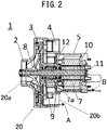
Fig. 2] Fig. 2 is a longitudinal cross-sectional view of the electric blower according to theembodiment 1 of the present invention taken along a plane passing through the center of a shaft. - [
Fig. 3] Fig. 3 is an exploded perspective view of the electric blower according to theembodiment 1 of the present invention. - [
Fig. 4] Fig. 4 is a side view of a rotor assembly of the electric blower according to theembodiment 1 of the present invention. - [
Fig. 5] Fig. 5 is a longitudinal cross-sectional view of a frame forming a portion of a housing of the electric blower according to theembodiment 1 of the present invention. - [
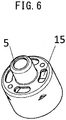
Fig. 6] Fig. 6 is a perspective view showing an external appearance of a frame forming a portion of a housing of an electric blower according to anembodiment 2 of the present invention as viewed from a side where an impeller is disposed. - [
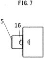
Fig. 7] Fig. 7 is a side view of a frame forming a portion of a housing of an electric blower according to anembodiment 3 of the present invention as viewed from a side on which a rib is formed. - Hereinafter, embodiments of the present invention are described with reference to drawings.
-
Fig. 1 is a perspective view showing an external appearance of an electric blower according to anembodiment 1 of the present invention as viewed from a frame side. -
Fig. 2 is a longitudinal cross-sectional view of the electric blower according to theembodiment 1 of the present invention taken along a plane passing through the center of a shaft. -
Fig. 3 is an exploded perspective view of the electric blower according to theembodiment 1 of the present invention. -
Fig. 4 is a side view of a rotor assembly of the electric blower according to theembodiment 1 of the present invention. -
Fig. 5 is a longitudinal cross-sectional view of a frame forming a portion of a housing of the electric blower according to theembodiment 1 of the present invention. - An
electric blower 1 includes arotor assembly 6 and ahousing 20. Thehousing 20 has anintake port 20a and adischarge port 20b, and accommodates therotor assembly 6 therein. Thehousing 20 includes afan cover 2 which covers animpeller 8 described later, adiffuser 3, abracket 4, aframe 5, and astator 7. - The
rotor assembly 6 includes ashaft 11, theimpeller 8, arotor core 10, and a pair ofbearings 9. Theimpeller 8 is mounted on theshaft 11, and generates a negative pressure at theintake port 20a by rotation. Therotor core 10 is mounted on theshaft 11, and applies a rotational force to theshaft 11 by thestator 7 described later. Inner peripheral surfaces of the pair ofbearings 9 are mounted on an outer periphery of theshaft 11, and outer peripheral surfaces of the pair ofbearings 9 are fixedly mounted on thehousing 20 side. The pair ofbearings 9 are arranged between theimpeller 8 and therotor core 10. Aspring 12 is provided between the pair ofbearings 9, and thespring 12 applies a preload to thebearings 9 in a direction that thebearings 9 separate from each other. - The
fan cover 2 has theintake port 20a, and covers theimpeller 8. An outer periphery of thefan cover 2 and an outer periphery of thebracket 4 are fixed with each other. Thebracket 4 accommodates thediffuser 3 therein. Thediffuser 3 is a disk-shaped member, and a plurality of guide blades are disposed in a fixed manner on theimpeller 8 side of thediffuser 3. When theimpeller 8 rotates in a state where theimpeller 8 is mounted on theshaft 11, air is fed outward in the radial direction from theimpeller 8, and pressure recovery is performed on the air by an air passage formed by the plurality of guide blades disposed on thediffuser 3 and thefan cover 2. A gap is formed between an outer edge of thediffuser 3 and an inner surface of an outer peripheral portion of thebracket 4, and air is guided to the back surface side of thediffuser 3, that is, to the side where thestator 7 is disposed through the gap. - The
frame 5 forms a portion of thehousing 20. Theframe 5 has a cylindrical shape rotationally symmetrical about theshaft 11, and the cylindrical shape includes a stepped portion. On a paper on whichFig. 5 is drawn, the right side end portion of theframe 5 is open. In theframe 5, a cylindrical portion (first cylindrical portion) having a smaller diameter forms abearing holding portion 13 which holds thebearings 9 in a state where outer peripheral surfaces of thebearings 9 are in contact with thebearing holding portion 13. In theframe 5, a cylindrical portion (second cylindrical portion) having a larger diameter forms astator holding portion 14 which holds thestator 7. As described above, theframe 5 is formed of an integral body of thebearing holding portion 13 and thestator holding portion 14. An end portion of the first cylindrical portion on the side which does not communicate with the second cylindrical portion has aflange portion 13a which comes into contact with an end portion of abearing 9 in an axial direction of thebearing 9. The center of the end portion is open. - As shown in
Fig. 3 , a center portion of thediffuser 3 and a center portion of thebracket 4 are open, and thebearing holding portion 13, which is the first cylindrical portion, is inserted into the center portions of thediffuser 3 and thebracket 4. - In mounting the
rotor assembly 6 into thehousing 20, first, therotor assembly 6 in a state where theimpeller 8 is not mounted on theshaft 11 is inserted into thehousing 20 through an open end of the second cylindrical portion of theframe 5 from thebearing 9 side. At this stage of operation, thebearing 9 on the side opposite to therotor core 10 is fixedly mounted on thebearing holding portion 13 in a state where an end portion of thebearing 9 in the axial direction is in contact with an inner surface of theflange portion 13a of the first cylindrical portion of theframe 5. Next, thestator 7 is inserted into thehousing 20 through the open end of the second cylindrical portion of theframe 5. Thestator 7 is fixed to thestator holding portion 14 in a state where thestator 7 faces therotor core 10. - Next, the operation of the electric blower according to the
embodiment 1 of the present invention is described. - When electric power is supplied to the
electric blower 1, a rotational force is applied to therotor core 10 through thestator 7 so that theimpeller 8 is rotationally driven about theshaft 11. When theimpeller 8 rotates, air in the vicinity of theimpeller 8 is pushed outward in the radial direction. A negative pressure is generated at theintake port 20a of thehousing 20 such that the air pushed outward is replenished from outside of thehousing 20. As indicated by a first airflow A inFig. 2 , flowing air sucked into theelectric blower 1 due to the driving of theimpeller 8 passes through thediffuser 3 and thebracket 4 and, thereafter, is discharged to the outside of thehousing 20 from thedischarge port 20b. - The pair of
bearings 9 are held and fixed in a contact state with thebearing holding portion 13 of theframe 5 forming a portion of thehousing 20. As a result, heat generated in thebearings 9 due to the rotation of therotor assembly 6 is directly transferred to theframe 5. The heat is transferred to theframe 5 so that theframe 5 functions as a heat sink. Theframe 5 ranging from thebearing holding portion 13 to thestator holding portion 14 is formed of an integral component. Accordingly, theframe 5 has a large surface area and hence, a high heat dissipation effect can be acquired. A portion of the first airflow A discharged from thedischarge port 20b flows along an outer periphery of theframe 5 and hence, a heat dissipation effect of theframe 5 can be further enhanced. - As a result, a temperature of the
bearings 9 is prevented from significantly increasing and hence, the lifespan of thebearings 9 is extended. Particularly, in an electric blower which uses an electric motor of a type which does not use a commutator and brush, such as a DC brushless motor, as a power source, a bearing is a part which is prone to malfunctioning first in many cases. Accordingly, the above-mentioned configuration leads to the extension of the lifespan of the electric blower as a whole. Further, by causing theframe 5 per se to function as a heat sink, it becomes unnecessary to provide parts having a heat dissipation effect besides theframe 5 and hence, the number of parts is reduced and it is possible to reduce the number of assembly steps. Moreover, thebearing holding portion 13 and thestator holding portion 14 are parts of the same component and hence, accuracy in positioning of thebearing holding portion 13 and accuracy in positioning of thestator holding portion 14 can be ensured by ensuring only accuracy in positioning of theframe 5 alone. Accordingly, a jig and bonding means become unnecessary at the time of assembly and hence, ease of assembly is enhanced. - The
bearings 9 are directly fixed to thebearing holding portion 13 in a contact state with thebearing holding portion 13. In the prior art, positions of outer peripheries of a pair of bearings are aligned using a cylindrical sleeve which surrounds the bearings. The sleeve is interposed between the bearings and a frame and hence, heat is not easily transferred directly to the frame from the bearings. In theelectric blower 1 of theembodiment 1, heat generated from thebearings 9 is directly transferred to theframe 5 and hence, a heat dissipation effect is enhanced. Further, a sleeve is not used so that the number of parts is reduced whereby it is possible to reduce the number of assembly steps. - As shown in
Fig. 5 , in theframe 5, an end portion of thebearing holding portion 13 on thestator holding portion 14 side projects in an axial direction of thebearing holding portion 13 toward thestator holding portion 14 side. With such a configuration, as shown inFig. 2 , astator supporting portion 7a of thestator 7 and thebearing 9 on thestator 7 side can be disposed in an overlapping manner in the axial direction and hence, a distance between thebearings 9 and therotor core 10 can be narrowed. A load in the radial direction is imposed on thebearings 9 with the rotation of therotor assembly 6. The narrower the distance between thebearings 9 and therotor core 10, the smaller the load becomes. Accordingly, such a configuration leads to the extension of the lifespan of the bearings. Further, an axial length of therotor assembly 6 can be shortened and hence, it is possible to reduce the size of the entireelectric blower 1. - The
frame 5 is desirably made of an aluminum alloy. An aluminum alloy has high thermal conductivity so that heat generated from thebearings 9 is easily transferred to theframe 5. Accordingly, it is possible to expect that theframe 5 has a high heat dissipation effect as a heat sink. - The
bearings 9 may be fixed to thebearing holding portion 13 by an adhesive agent. For example, when theframe 5 is made of an aluminum alloy, and thebearings 9 are made of a material other than an aluminum alloy, a material for forming theframe 5 and a material for forming thebearings 9 differ from each other in coefficient of thermal expansion. When thebearings 9 generate heat due to the rotation of theshaft 11, theframe 5 is also heated. When thebearings 9 and theframe 5 thermally expand, due to the difference in coefficient of thermal expansion, a gap may be formed between theframe 5 and thebearings 9. In this situation, when thebearings 9 are fixed to thebearing holding portion 13 by an adhesive agent having an elastic modulus smaller than an elastic modulus of thebearings 9 or thebearing holding portion 13, bonding between thebearings 9 and thebearing holding portion 13 can be maintained. Accordingly, even when thebearings 9 and theframe 5 thermally expand, it is possible to suppress thebearing 9 escaping from thebearing holding portion 13. - As described above, the electric blower of the
embodiment 1 includes the rotor assembly, and the housing accommodating the rotor assembly therein, and having the intake port and the discharge port. The rotor assembly includes the shaft, the impeller mounted on the shaft, and generating a negative pressure at the intake port by rotation, the rotor core mounted on the shaft, and the pair of bearings having the inner peripheral side thereof mounted on the outer periphery of the shaft, and having the outer peripheral side thereof fixedly mounted on the housing side. The pair of bearings are arranged between the impeller and the rotor core. The housing includes the frame formed of the integral body of the bearing holding portion and the stator holding portion. The bearing holding portion holds the pair of bearings in a state where the outer peripheral surfaces of the bearings are in contact with the bearing holding portion. The stator holding portion holds the stator which drives the rotor core. With such a configuration, according to theembodiment 1, it is possible to provide an electric blower where heat generated from the bearings can be efficiently dissipated from the frame. - Further, the end portion of the bearing holding portion projects in the axial direction of the bearing holding portion toward the stator holding portion side and hence, the stator supporting portion and the bearing on the stator side can be disposed in an overlapping manner in the axial. Accordingly, the distance between the bearings and the rotor core can be narrowed. The load in the radial direction is imposed on the bearings with the rotation of the rotor assembly. The narrower the distance between the bearings and the rotor core, the smaller the load becomes. Therefore, such a configuration leads to the extension of the lifespan of the bearings. Further, the axial length of the rotor assembly can be shortened and hence, it is possible to reduce the size of the electric blower.
- It may be possible to adopt a structure where the bearing holding portion of the frame does not project toward the stator holding portion side. With such the structure, the frame is allowed to have a shape which can be formed by drawing processing. Accordingly, production cost can be lowered.
- Further, the frame is made of an aluminum alloy and hence, heat generated from the bearings is easily transferred to the frame whereby heat generated from the bearings can be efficiently dissipated from the frame.
- The bearings are fixed to the bearing holding portion by the adhesive agent having the elastic modulus smaller than the elastic modulus of the bearings or the bearing holding portion. Accordingly, it is possible to suppress the bearing escaping from the bearing holding portion.
-
Fig. 6 is a perspective view showing an external appearance of a frame forming a portion of a housing of an electric blower according to anembodiment 2 of the present invention as viewed from a side where an impeller is disposed. The electric blower of theembodiment 2 differs from the electric blower of theembodiment 1 with respect to a point that a surface of aframe 5 perpendicular to ashaft 11 hasair holes 15, wherein the surface connects abearing holding portion 13, which forms a first cylindrical portion, and a stator holding portion, which forms a second cylindrical portion, with each other. - As indicated by a first airflow A in
Fig. 2 , flowing air sucked into theelectric blower 1 due to the driving of animpeller 8 passes through adiffuser 3 and abracket 4 and, thereafter, is discharged to the outside of theframe 5. A portion of the first airflow A which is discharged from adischarge port 20b flows along an outer periphery of theframe 5 thus cooling theframe 5 from an outer surface of theframe 5. By forming the air holes 15 in theframe 5, as indicated by a second airflow B inFig. 2 , the airflow flows also into theframe 5. The airflow which enters theframe 5 through the air holes 15 is discharged to the outside of theframe 5 through a gap (not shown in the drawing) formed on the leeward side of astator 7. As described above, theframe 5 is cooled from both the outer surface and an inner surface so that the heat dissipation effect of theframe 5 can be further enhanced. - As described above, in the electric blower of the
embodiment 2, the frame has the air holes through which the flow of air generated due to the driving of the impeller flows into the frame. With such a configuration, the airflow which enters the frame through the air holes cools the inner surface of the frame so that heat generated from the bearings can be efficiently dissipated from the frame. -
Fig. 7 is a side view of a frame forming a portion of a housing of an electric blower according to anembodiment 3 of the present invention as viewed from a side on which a rib is formed. The electric blower of theembodiment 3 differs from the electric blower of theembodiment 2 with respect to a point that a frame includes the rib in a flow passage for a flow of air generated due to the driving of an impeller. - As indicated by a first airflow A in
Fig. 2 , flowing air sucked into theelectric blower 1 due to the driving of animpeller 8 passes through adiffuser 3 and abracket 4 and, thereafter, is discharged to the outside of theframe 5. A portion of the first airflow A which is discharged from adischarge port 20b flows along an outer periphery of theframe 5 thus cooling theframe 5 from an outer surface of theframe 5. By forming the air holes 15 in theframe 5, as indicated by a second airflow B inFig. 2 , the airflow flows also into theframe 5. The airflow which enters theframe 5 through the air holes 15 is discharged to the outside of theframe 5 through a gap (not shown in the drawing) formed on the leeward side of astator 7. As described above, theframe 5 is cooled from both the outer surface and an inner surface so that the heat dissipation effect of theframe 5 can be further enhanced. - As shown in
Fig. 7 , theframe 5 includes arib 16 in the flow passage for the flow of air generated due to the driving of the impeller. Therib 16 is formed on a surface of theframe 5 described in theembodiment 2 which has the air holes 15. Therib 16 may have either of a shape which projects toward thebearing holding portion 13 side from the surface in which the air holes 15 are formed or a shape which projects toward thestator holding portion 14 side from the surface in which the air holes 15 are formed. Therib 16 desirably has a flat shape having a wide surface. With the formation of therib 16, a surface area of theframe 5 increases and hence, the heat dissipation effect is enhanced. - Further, the
flat rib 16 is desirably disposed along the flow of the second airflow B. Therib 16 is formed on the surface of theframe 5 which has the air holes 15 such that therib 16 extends radially along the radial direction. The second airflow B flows inward in the radial direction toward theshaft 11 from a gap formed between an outer edge of thediffuser 3 and an inner surface of an outer peripheral portion of thebracket 4. For example, when therib 16 has the shape which projects toward thebearing holding portion 13 side from the surface in which the air holes 15 are formed, the second airflow B flows along a side surface of theflat rib 16 disposed radially along the radial direction. With such a configuration, the second airflow B efficiently cools therib 16. Accordingly, a heat dissipation effect of theframe 5 can be further enhanced. The efficient cooling of therib 16 also leads to the enhancement of the strength of theframe 5. - The
flat rib 16 may be disposed such that the wide surface of therib 16 is orthogonal to a direction along which the second airflow B flows. In this case, by forming the air holes 15 on the windward side of the wide surface of therib 16, the second airflow B which impinges on therib 16 flows along the wide surface. The second airflow B is guided so as to flow toward the air holes 15. Therib 16 may be formed such that a distal end of therib 16 on thebearing holding portion 13 side inclines toward the upstream side in the second airflow B. The second airflow B is efficiently guided so as to flow toward the air holes 15. As a result, the second airflow B effectively flows into theframe 5 from the air holes 15 so that the airflow cools the inner surface of the frame whereby heat generated from the bearings can be efficiently dissipated from the frame. - When the
rib 16 has a shape which projects toward thestator holding portion 14 side from the surface in which the air holes 15 are formed, therib 16 may be disposed radially along the radial direction. Therib 16 may be disposed such that the direction of therib 16 is rotated by 90 degrees so that a line perpendicular to the wide surface of theflat rib 16 extends radially along the radial direction. The second airflow B which enters theframe 5 from the air holes 15 flows along the wide surface of therib 16 thus efficiently cooling therib 16. Accordingly, a heat dissipation effect of theframe 5 can be further enhanced. - As described above, the
rib 16 is formed on the surface in which the air holes 15 are formed. However, the air holes 15 may not be formed in the surface. For example, in theframe 5 having no air holes 15, therib 16 may be formed on an outer side of thestator holding portion 14. Therib 16 is formed in the flow passage for the first airflow A so that therib 16 is cooled whereby a heat dissipation effect of theframe 5 can be enhanced. - As described above, in the electric blower of the
embodiment 3, the frame includes the rib formed in the flow passage for the flow of air generated due to the driving of the impeller. Accordingly, an airflow generated due to the driving of the impeller cools the rib. The frame on which the rib is formed is cooled and hence, heat generated from the bearings can be efficiently dissipated from the frame. - The electric blower which has been described in the
embodiment 1, theembodiment 2 or theembodiment 3, can be used as a drive source of an electric vacuum cleaner, for example. The lifespan of the electric blower directly relates to the product lifespan of an electric vacuum cleaner. Accordingly, by loading an electric blower with the extended lifespan into an electric vacuum cleaner, it is possible to expect the acquisition of an advantageous effect of extending the product lifespan of the electric vacuum cleaner. - The electric blower according to the present invention is utilized as an electric blower which uses an electric motor of a type which does not use a commutator and brush, such as a DC brushless motor, as a power source, for example. Further, the electric blower according to the present invention is loaded into an electric vacuum cleaner, for example.
-
- 1 electric blower
- 2 fan cover
- 3 diffuser
- 4 bracket
- 5 frame
- 6 rotor assembly
- 7 stator
- 7a stator supporting portion
- 8 impeller
- 9 bearing
- 10 rotor core
- 11 shaft
- 12 spring
- 13 bearing holding portion
- 13a flange portion
- 14 stator holding portion
- 15 air hole
- 16 rib
- 20 housing
- 20a intake port
- 20b discharge port
- A first airflow
- B second airflow
Claims (7)
- An electric blower comprising:a rotor assembly; anda housing accommodating the rotor assembly, and having an intake port and a discharge port, whereinthe rotor assembly includes:a shaft;an impeller mounted on the shaft, and generating a negative pressure at the intake port by rotation;a rotor core mounted on the shaft; anda pair of bearings having an inner peripheral side mounted on an outer periphery of the shaft, and having an outer peripheral side fixedly mounted on the housing,the pair of bearings are arranged between the impeller and the rotor core, and the housing includes a frame formed of an integral body of a bearing holding portion and a stator holding portion, the bearing holding portion holding the pair of bearings in a state where outer peripheral surfaces of the bearings are in contact with the bearing holding portion, and the stator holding portion holding a stator which drives the rotor core.
- The electric blower according to claim 1, wherein
the bearing holding portion projects in an axial direction of the bearing holding portion toward the stator holding portion side. - The electric blower according to claim 1 or claim 2, wherein
the frame is made of an aluminum alloy. - The electric blower according to any one of claim 1 to claim 3, wherein
the bearing is fixed to the bearing holding portion by an adhesive agent having an elastic modulus smaller than an elastic modulus of the bearing or the bearing holding portion. - The electric blower according to any one of claim 1 to claim 4, wherein
the frame has an air hole through which a flow of air generated due to the driving of the impeller flows into the frame. - The electric blower according to any one of claim 1 to claim 5, wherein
the frame includes a rib in a flow passage for the flow of air generated due to the driving of the impeller. - An electric vacuum cleaner comprising the electric blower described in any one of claim 1 to claim 6.
Applications Claiming Priority (2)
| Application Number | Priority Date | Filing Date | Title |
|---|---|---|---|
| JP2016065729 | 2016-03-29 | ||
| PCT/JP2017/002560 WO2017169033A1 (en) | 2016-03-29 | 2017-01-25 | Electric fan and electric vacuum cleaner equipped with same |
Publications (2)
| Publication Number | Publication Date |
|---|---|
| EP3438461A1 true EP3438461A1 (en) | 2019-02-06 |
| EP3438461A4 EP3438461A4 (en) | 2019-03-13 |
Family
ID=59962813
Family Applications (1)
| Application Number | Title | Priority Date | Filing Date |
|---|---|---|---|
| EP17773583.4A Withdrawn EP3438461A4 (en) | 2016-03-29 | 2017-01-25 | ELECTRIC BLOWER AND ELECTRIC VACUUM EQUIPPED WITH THE SAME |
Country Status (4)
| Country | Link |
|---|---|
| US (1) | US20190101129A1 (en) |
| EP (1) | EP3438461A4 (en) |
| JP (1) | JPWO2017169033A1 (en) |
| WO (1) | WO2017169033A1 (en) |
Cited By (3)
| Publication number | Priority date | Publication date | Assignee | Title |
|---|---|---|---|---|
| CN113508513A (en) * | 2019-03-11 | 2021-10-15 | 三菱电机株式会社 | Electric motors, electric blowers, electric vacuum cleaners, and hand dryers |
| WO2022052137A1 (en) * | 2020-09-11 | 2022-03-17 | 苏州甘泰精密机械有限公司 | Rotary cleaning machine |
| WO2022052138A1 (en) * | 2020-09-11 | 2022-03-17 | 苏州甘泰精密机械有限公司 | Liquid collection type cleaning machine |
Families Citing this family (9)
| Publication number | Priority date | Publication date | Assignee | Title |
|---|---|---|---|---|
| CN107061320B (en) * | 2017-03-13 | 2019-04-02 | 美的集团股份有限公司 | Electric fan and vacuum cleaner having the same |
| JP6771663B2 (en) * | 2017-05-01 | 2020-10-21 | 三菱電機株式会社 | Electric blowers, vacuum cleaners, and hand dryers |
| JP7145613B2 (en) * | 2018-01-05 | 2022-10-03 | 三菱電機株式会社 | Rotating electric machine, blower, and method for manufacturing rotating electric machine |
| JP6988548B2 (en) * | 2018-02-20 | 2022-01-05 | 三菱電機株式会社 | How to make fan motors, fan motors and vacuum cleaners |
| CN111742148B (en) * | 2018-02-28 | 2022-02-22 | 三菱电机株式会社 | Electric blower, electric vacuum cleaner, and hand dryer |
| WO2019167153A1 (en) * | 2018-02-28 | 2019-09-06 | 三菱電機株式会社 | Electric blower, electric vacuum cleaner and hand dryer |
| JP7044083B2 (en) * | 2019-03-01 | 2022-03-30 | 三菱電機株式会社 | An electric blower and a vacuum cleaner equipped with the electric blower |
| JP7369579B2 (en) * | 2019-09-30 | 2023-10-26 | 株式会社マキタ | Rotating brush and robot dust collector |
| KR102499760B1 (en) * | 2020-12-30 | 2023-02-15 | 엘지전자 주식회사 | Electric motor assembly |
Family Cites Families (14)
| Publication number | Priority date | Publication date | Assignee | Title |
|---|---|---|---|---|
| JPS568892U (en) * | 1979-06-29 | 1981-01-26 | ||
| JPS59196994A (en) * | 1983-04-21 | 1984-11-08 | Matsushita Electric Ind Co Ltd | Manufacturing method of magnetically coupled pump |
| US5347187A (en) * | 1991-08-29 | 1994-09-13 | Matsushita Electric Industrial Co., Ltd. | Miniature electric motor |
| WO2003054394A1 (en) * | 2001-12-21 | 2003-07-03 | Matsushita Electric Industrial Co., Ltd. | Electrically powered blower |
| EP1995853A1 (en) * | 2007-05-24 | 2008-11-26 | Alcatel Lucent | Electric Motor |
| JP2013024133A (en) * | 2011-07-21 | 2013-02-04 | Panasonic Corp | Motor-driven air blower, and vacuum cleaner employing the same |
| JP2013029034A (en) * | 2011-07-27 | 2013-02-07 | Panasonic Corp | Electric blower and vacuum cleaner |
| GB2513664B (en) * | 2013-05-03 | 2016-01-06 | Dyson Technology Ltd | Compressor |
| GB2513665B (en) * | 2013-05-03 | 2016-01-06 | Dyson Technology Ltd | Compressor |
| JP6396083B2 (en) * | 2014-06-09 | 2018-09-26 | 日立アプライアンス株式会社 | Electric blower and vacuum cleaner |
| JP6504754B6 (en) * | 2014-06-18 | 2019-06-05 | 日立グローバルライフソリューションズ株式会社 | Electric blower and vacuum cleaner using the same |
| US10125791B2 (en) * | 2014-11-17 | 2018-11-13 | Nidec Corporation | Blower |
| GB2545269B (en) * | 2015-12-11 | 2018-02-28 | Dyson Technology Ltd | An electric motor |
| ITUB20160930A1 (en) * | 2016-02-22 | 2017-08-22 | Sit Spa | STRUCTURE OF ELECTRIC MOTOR IN PARTICULAR FOR FANS FOR COMBUSTION AIR, OR FOR MIXTURE OF AIR / COMBUSTION GAS, IN GAS BURNERS, STATIC GROUP FOR SUCH ELECTRIC MOTOR STRUCTURE AND ASSEMBLY PROCEDURE FOR SUCH STATIC GROUP |
-
2017
- 2017-01-25 JP JP2018508451A patent/JPWO2017169033A1/en active Pending
- 2017-01-25 US US16/087,606 patent/US20190101129A1/en not_active Abandoned
- 2017-01-25 EP EP17773583.4A patent/EP3438461A4/en not_active Withdrawn
- 2017-01-25 WO PCT/JP2017/002560 patent/WO2017169033A1/en not_active Ceased
Cited By (3)
| Publication number | Priority date | Publication date | Assignee | Title |
|---|---|---|---|---|
| CN113508513A (en) * | 2019-03-11 | 2021-10-15 | 三菱电机株式会社 | Electric motors, electric blowers, electric vacuum cleaners, and hand dryers |
| WO2022052137A1 (en) * | 2020-09-11 | 2022-03-17 | 苏州甘泰精密机械有限公司 | Rotary cleaning machine |
| WO2022052138A1 (en) * | 2020-09-11 | 2022-03-17 | 苏州甘泰精密机械有限公司 | Liquid collection type cleaning machine |
Also Published As
| Publication number | Publication date |
|---|---|
| WO2017169033A1 (en) | 2017-10-05 |
| US20190101129A1 (en) | 2019-04-04 |
| JPWO2017169033A1 (en) | 2018-11-22 |
| EP3438461A4 (en) | 2019-03-13 |
Similar Documents
| Publication | Publication Date | Title |
|---|---|---|
| EP3438461A1 (en) | Electric fan and electric vacuum cleaner equipped with same | |
| US9531239B2 (en) | Active cooling of a motor having an integrated cooling channel | |
| US9450474B2 (en) | Active cooling of a motor | |
| US7701097B2 (en) | Fan, motor and impeller thereof | |
| JP4935048B2 (en) | Centrifugal fan | |
| JP6382122B2 (en) | Electric blower and vacuum cleaner equipped with the same | |
| EP3160019B1 (en) | Motor structure capable of dissipating heat therein | |
| US20150008771A1 (en) | Motor having cooling means | |
| US10760578B2 (en) | Vacuum pump with heat generation element in relation to housing | |
| US20210104934A1 (en) | Fan motor | |
| US20190191949A1 (en) | Blowing device and vacuum cleaner | |
| CN107112858A (en) | Electric machines with deflectors | |
| US7507068B2 (en) | Heat-dissipating mechanism for a motor | |
| US11700980B2 (en) | Electric blower, vacuum cleaner, and hand drying device | |
| JP6178674B2 (en) | Blower | |
| US11454246B2 (en) | Electric blower, vacuum cleaner, and hand drying device | |
| CN111971878A (en) | Rotary wing device | |
| JP6470055B2 (en) | Electric blower and electric vacuum cleaner using the same | |
| CN101714793B (en) | Coil support for rotating electrical machine | |
| CN104734423A (en) | Electromotor | |
| CN118548229A (en) | Blower | |
| CN101494401B (en) | Motor and fan with dust-proof and heat-dissipating functions | |
| CN100594304C (en) | Forced heat dissipation structure of the motor | |
| CN114448173B (en) | Self-cooling motor and hot air circulation device suitable for the same | |
| JP2005291050A (en) | Centrifugal fan |
Legal Events
| Date | Code | Title | Description |
|---|---|---|---|
| STAA | Information on the status of an ep patent application or granted ep patent |
Free format text: STATUS: THE INTERNATIONAL PUBLICATION HAS BEEN MADE |
|
| PUAI | Public reference made under article 153(3) epc to a published international application that has entered the european phase |
Free format text: ORIGINAL CODE: 0009012 |
|
| STAA | Information on the status of an ep patent application or granted ep patent |
Free format text: STATUS: REQUEST FOR EXAMINATION WAS MADE |
|
| 17P | Request for examination filed |
Effective date: 20180921 |
|
| AK | Designated contracting states |
Kind code of ref document: A1 Designated state(s): AL AT BE BG CH CY CZ DE DK EE ES FI FR GB GR HR HU IE IS IT LI LT LU LV MC MK MT NL NO PL PT RO RS SE SI SK SM TR |
|
| AX | Request for extension of the european patent |
Extension state: BA ME |
|
| A4 | Supplementary search report drawn up and despatched |
Effective date: 20190212 |
|
| RIC1 | Information provided on ipc code assigned before grant |
Ipc: F04D 25/06 20060101ALI20190205BHEP Ipc: H02K 5/173 20060101ALI20190205BHEP Ipc: F04D 29/059 20060101ALI20190205BHEP Ipc: F04D 29/62 20060101ALI20190205BHEP Ipc: H02K 9/06 20060101ALI20190205BHEP Ipc: F04D 25/08 20060101AFI20190205BHEP Ipc: F04D 29/58 20060101ALI20190205BHEP Ipc: F04D 29/42 20060101ALI20190205BHEP |
|
| DAV | Request for validation of the european patent (deleted) | ||
| DAX | Request for extension of the european patent (deleted) | ||
| STAA | Information on the status of an ep patent application or granted ep patent |
Free format text: STATUS: THE APPLICATION IS DEEMED TO BE WITHDRAWN |
|
| 18D | Application deemed to be withdrawn |
Effective date: 20190912 |