EP3438445A1 - Fuel pressurising device - Google Patents
Fuel pressurising device Download PDFInfo
- Publication number
- EP3438445A1 EP3438445A1 EP18183555.4A EP18183555A EP3438445A1 EP 3438445 A1 EP3438445 A1 EP 3438445A1 EP 18183555 A EP18183555 A EP 18183555A EP 3438445 A1 EP3438445 A1 EP 3438445A1
- Authority
- EP
- European Patent Office
- Prior art keywords
- dimv
- inlet
- pumping
- fuel
- cycle
- Prior art date
- Legal status (The legal status is an assumption and is not a legal conclusion. Google has not performed a legal analysis and makes no representation as to the accuracy of the status listed.)
- Granted
Links
Images


Classifications
-
- F—MECHANICAL ENGINEERING; LIGHTING; HEATING; WEAPONS; BLASTING
- F02—COMBUSTION ENGINES; HOT-GAS OR COMBUSTION-PRODUCT ENGINE PLANTS
- F02M—SUPPLYING COMBUSTION ENGINES IN GENERAL WITH COMBUSTIBLE MIXTURES OR CONSTITUENTS THEREOF
- F02M59/00—Pumps specially adapted for fuel-injection and not provided for in groups F02M39/00 -F02M57/00, e.g. rotary cylinder-block type of pumps
- F02M59/20—Varying fuel delivery in quantity or timing
- F02M59/36—Varying fuel delivery in quantity or timing by variably-timed valves controlling fuel passages to pumping elements or overflow passages
- F02M59/366—Valves being actuated electrically
-
- F—MECHANICAL ENGINEERING; LIGHTING; HEATING; WEAPONS; BLASTING
- F02—COMBUSTION ENGINES; HOT-GAS OR COMBUSTION-PRODUCT ENGINE PLANTS
- F02M—SUPPLYING COMBUSTION ENGINES IN GENERAL WITH COMBUSTIBLE MIXTURES OR CONSTITUENTS THEREOF
- F02M41/00—Fuel-injection apparatus with two or more injectors fed from a common pressure-source sequentially by means of a distributor
- F02M41/08—Fuel-injection apparatus with two or more injectors fed from a common pressure-source sequentially by means of a distributor the distributor and pumping elements being combined
- F02M41/14—Fuel-injection apparatus with two or more injectors fed from a common pressure-source sequentially by means of a distributor the distributor and pumping elements being combined rotary distributor supporting pump pistons
- F02M41/1405—Fuel-injection apparatus with two or more injectors fed from a common pressure-source sequentially by means of a distributor the distributor and pumping elements being combined rotary distributor supporting pump pistons pistons being disposed radially with respect to rotation axis
- F02M41/1411—Fuel-injection apparatus with two or more injectors fed from a common pressure-source sequentially by means of a distributor the distributor and pumping elements being combined rotary distributor supporting pump pistons pistons being disposed radially with respect to rotation axis characterised by means for varying fuel delivery or injection timing
- F02M41/1427—Arrangements for metering fuel admitted to pumping chambers, e.g. by shuttles or by throttle-valves
-
- F—MECHANICAL ENGINEERING; LIGHTING; HEATING; WEAPONS; BLASTING
- F02—COMBUSTION ENGINES; HOT-GAS OR COMBUSTION-PRODUCT ENGINE PLANTS
- F02M—SUPPLYING COMBUSTION ENGINES IN GENERAL WITH COMBUSTIBLE MIXTURES OR CONSTITUENTS THEREOF
- F02M59/00—Pumps specially adapted for fuel-injection and not provided for in groups F02M39/00 -F02M57/00, e.g. rotary cylinder-block type of pumps
- F02M59/20—Varying fuel delivery in quantity or timing
- F02M59/205—Quantity of fuel admitted to pumping elements being metered by an auxiliary metering device
-
- F—MECHANICAL ENGINEERING; LIGHTING; HEATING; WEAPONS; BLASTING
- F02—COMBUSTION ENGINES; HOT-GAS OR COMBUSTION-PRODUCT ENGINE PLANTS
- F02M—SUPPLYING COMBUSTION ENGINES IN GENERAL WITH COMBUSTIBLE MIXTURES OR CONSTITUENTS THEREOF
- F02M59/00—Pumps specially adapted for fuel-injection and not provided for in groups F02M39/00 -F02M57/00, e.g. rotary cylinder-block type of pumps
- F02M59/20—Varying fuel delivery in quantity or timing
- F02M59/36—Varying fuel delivery in quantity or timing by variably-timed valves controlling fuel passages to pumping elements or overflow passages
- F02M59/366—Valves being actuated electrically
- F02M59/367—Pump inlet valves of the check valve type being open when actuated
-
- F—MECHANICAL ENGINEERING; LIGHTING; HEATING; WEAPONS; BLASTING
- F02—COMBUSTION ENGINES; HOT-GAS OR COMBUSTION-PRODUCT ENGINE PLANTS
- F02M—SUPPLYING COMBUSTION ENGINES IN GENERAL WITH COMBUSTIBLE MIXTURES OR CONSTITUENTS THEREOF
- F02M59/00—Pumps specially adapted for fuel-injection and not provided for in groups F02M39/00 -F02M57/00, e.g. rotary cylinder-block type of pumps
- F02M59/44—Details, components parts, or accessories not provided for in, or of interest apart from, the apparatus of groups F02M59/02 - F02M59/42; Pumps having transducers, e.g. to measure displacement of pump rack or piston
- F02M59/46—Valves
- F02M59/466—Electrically operated valves, e.g. using electromagnetic or piezoelectric operating means
-
- F—MECHANICAL ENGINEERING; LIGHTING; HEATING; WEAPONS; BLASTING
- F02—COMBUSTION ENGINES; HOT-GAS OR COMBUSTION-PRODUCT ENGINE PLANTS
- F02M—SUPPLYING COMBUSTION ENGINES IN GENERAL WITH COMBUSTIBLE MIXTURES OR CONSTITUENTS THEREOF
- F02M2700/00—Supplying, feeding or preparing air, fuel, fuel air mixtures or auxiliary fluids for a combustion engine; Use of exhaust gas; Compressors for piston engines
- F02M2700/13—Special devices for making an explosive mixture; Fuel pumps
- F02M2700/1317—Fuel pumpo for internal combustion engines
- F02M2700/1358—Fuel pump with control of fuel inlet to the pumping chamber
Definitions
- the present invention relates to a pressurising device of a fuel injection equipment wherein a single metering valve controls the inlet flow into a high pressure pump performing one or two pumping cycles.
- a diesel fuel injection equipment arranged on an internal combustion engine comprises a high pressure pump receiving a low pressure upstream fuel flow and delivering to a common rail and to injectors a high pressure downstream flow.
- An inlet metering valve connected to a command unit limits said upstream flow to the quantity required to match the engine torque and power demand.
- a pressurising device of a direct fuel injection equipment (FIE) of a diesel internal combustion engine comprising a digital inlet metering valve (DIMV), controlling an inlet fluid communication to a pump performing, in use, a pumping cycle in a pumping head, said cycle being the alternation of a filling phase and a compression phase.
- DIMV digital inlet metering valve
- the DIMV and the pump are integrated in a single housing forming in compact assembly of the FIE.
- the pump comprises:
- the DIMV comprises an electro 2-way valve controlling the inlet into a buffer chamber connected to the inlet.
- the fuel fills said buffer chamber and from there fills the compression chamber of the pumping head that is in filling phase PF and which volume increases.
- the pump is a twin-head-pump performing, in use, said first pumping cycle in said first pumping head and, a second pumping cycle in a second pumping head, said cycles being the alternation of a filling phase and a compression phase, said first and second cycles being in opposition of phase of one another so that, the compression phase of a cycle is simultaneous to the filling phase of the other cycle.
- the DIMV controls the inlet fluid communication to said twin-head-pump and it switches to an open state after either cycle initiates a filling phase and, switches to a closed state when approaching the end of said filling phase.
- the DIMV and the twin-head-pump are integrated in a single housing forming in compact assembly of the FIE.
- low pressure fuel exiting the DIMV is delivered to the twin-head-pump wherein it is compressed in the first pumping cycle or in the second pumping cycle.
- twin-head-pump comprises:
- the fuel fills said buffer chamber and from there fills the compression chamber, of the pumping head, that is in filling phase PF and which volume increases.
- the invention further extends to a fuel injection equipment for a diesel internal combustion engine, said FIE comprising a pressurising unit as previously described.
- the invention further extends to a control method of a fuel injection equipment as claimed in claim, the method comprising the following steps:
- the step switching the DIMV to an open state enables fuel to fill the buffer chamber when the pumping cycle initiates a filling phase, the inlet valves being closed preventing fuel entry into the compression chamber then, subsequent to said switching step, the method comprises the step
- the method may comprise the following steps:
- the step switching the DIMV to an open state enables fuel to fill the buffer chamber when either of the pumping cycles initiates a filling phase, both first and second inlet valves, being closed preventing fuel entry into the compression chambers then, subsequent to said switching step, the method comprises the step
- the invention further extends to an electronic command unit adapted execute a method as described above.
- a diesel internal combustion engine provided with a direct fuel injection equipment 6 is controlled by a command unit (ECU) 8.
- ECU command unit
- diesel fuel stored in a tank at low pressure, or atmospheric pressure is sent to a pressurising device 10 comprising a digital inlet metering valve 12, hereafter DIMV 12, and a high pressure pump 14.
- DIMV 12 digital inlet metering valve 12
- high pressure pump 14 After being pressurised in said pump 14, the fuel is delivered to a common rail then to fuel injectors, which along with the tank are drawn in dotted lines in the figures.
- the pump 14 comprises a pumping head 16 and, upon command signals received from the ECU 8 the DIMV 12 controls the upstream flow entering said pumping head 16.
- the DIMV 12 is an electro actuated 2-way valve comprising an actuator such as a solenoid, controlling a valve member opening, or closing, the fuel entry into a buffer chamber 20 wherefrom said fuel is oriented toward the pumping head 16; said pumping head 16 performing a pumping cycle C1, shown in figure 2 , that is the alternation of a filling phase PF and of a compression phase PC.
- the pump 14 comprises two or more pumping heads, all performing a pumping cycle in phase with each other.
- the buffer chamber 20 is, in this alternative, in fluid communication with all the pumping heads of the pump 14.
- fuel is pressurised in a compression chamber 22 defined at the end of a bore 24 in which a piston 26 urged by a rotating cam 28 is reciprocally guided along a pumping axis X1.
- a compression chamber 22 defined at the end of a bore 24 in which a piston 26 urged by a rotating cam 28 is reciprocally guided along a pumping axis X1.
- pressure drops in said compression chamber 22 opening an inlet 32 by moving an inlet valve member 30.
- Fuel at low pressure is sucked through said inlet 32 in said compression chamber 22.
- the pressure in said compression chamber 22 rises moving the inlet valve member 30 into a closed position of the inlet 32.
- the fuel is then pressurised in said compression chamber 22 prior to being expelled when said pressure overcomes a threshold forcing a outlet valve member 34 to open an outlet 36.
- the figures show a single rotating cam urging the pistons but, in alternative embodiments, the pump 14 may comprise several cams.
- the cam 28 is can be a multi-lobe cam and, the pumping axes are arranged to create the simultaneity of the pumping cycles. For instance, in a two head pump an elliptical cam having two lobes, may urge simultaneously two pistons opposed at 180° and, in a four head pump, a square came (with rounded corners) simultaneously urges four piston arranged at 90° from each other.
- the inlet valve members 30 is a passive valve moving under the influence of pressure difference between the compression chamber and the other side of the valve member, the inlet channel.
- the valve 30 can cooperate with an actuator, such as a solenoid, which advances the opening or retards the closing of the valve member.
- a DIMV 12 controls the inlet to the pumping head.
- the following sequence, illustrated by figure 2 where the cycle C1 starts with a filling phase PF describes steps of a method 100 executed by the ECU 8 in order to control the fuel quantity compressed in the compression chamber.
- the control method 100 comprises the following steps:
- the fuel enters the compression chamber as soon as the inlet valve opens at beginning of the filing phase PF and, when the DIMV 12 closes the pressure difference between the buffer chamber 20 and the compression chamber cancels very rapidly, this closing the inlet valve and ending said fuel entry right after closing the DIMV 12.
- the fuel quantity in the compression chamber is then controlled by closing the DIMV 12.
- the pressurising device 10 of the fuel injection equipment 6 comprises the DIMV 12, and a twin-head-pump 14.
- the twin-head-pump 14 comprises the first pumping head 16, previously identified as the pumping head 16, and a second pumping head 18.
- the DIMV 12 controls the upstream flow entering said two pumping heads 16, 18.
- the DIMV 12 is an electro actuated 2-way valve comprising an actuator such as a solenoid controlling a valve member opening, or closing, the fuel entry into the buffer chamber 20 wherefrom said fuel is oriented toward the first pumping head 16 performing the first pumping cycle C1 or, toward the second pumping head 18 performing a second pumping cycle C2.
- Each pumping cycle C1, C2 is the alternation of a filling phase PF and a compression phase PC and, in said twin-head-pump 14 the two cycles C1, C2 are in opposition of phase, the filling phase PF of a pumping head being simultaneous to the compression phase PC of the other pumping head.
- the pump 14 is a multi-head pump comprising three, four or more pumping heads, some performing said first pumping cycle C1, the other performing the second pumping cycle C2 in opposition of phase with C1.
- the buffer chamber 20 is in fluid communication with all the pumping heads of the multi-head pump 14.
- the first pumping head 16 is, as previously described, with the first compression chamber 22, the first bore 24, the first piston 26, the first pumping axis X1, the first inlet valve member 30, the first inlet 32, the first outlet valve member 34 and the first outlet 36.
- the cam 28 is typically a two-lobe cam opposed at 180°, as in an oval or elliptical shape and, the pumping axis X1, X2 are at 90° from each other.
- Said arrangement of cam profile and angled axis creates the opposition of phases although other arrangements, such as a one lobe cam and two pistons opposed at 180° or, pistons urged by different cams may achieve a similar result.
- a third head is opposed at 180° of the first head 16 and, a fourth head is opposed at 180° of the second head 18, thus the first and third heads performing the first cycle C1 and, the second and fourth heads performing the second cycle C2.
- first and second inlet valve members 30, 44 are passive valves moving under the influence of difference between the pressure in the compression chamber and the pressure on the other side of the valve member.
- the valves 30, 44 can cooperate with an actuator, such as a solenoid, which advances the opening or retards the closing of the valve member.
- a single DIMV 12 controls the inlet to the two pumping heads.
- the control method 100 comprises the following steps:
- the fuel enters the compression chamber as soon as the inlet valve member opens at beginning of the filing phase PF and, later in said phase when the DIMV 12 closes the pressure difference between the buffer chamber 20 and the compression chamber cancels which closes the inlet valve member right after the DIMV 12 closes, ending said fuel entry.
- the fuel quantity in the compression chamber is then controlled by closing the DIMV 12.
- DIMV 12 and buffer chamber 20 serve two pumping head.
Landscapes
- Engineering & Computer Science (AREA)
- Chemical & Material Sciences (AREA)
- Combustion & Propulsion (AREA)
- Mechanical Engineering (AREA)
- General Engineering & Computer Science (AREA)
- Physics & Mathematics (AREA)
- Electromagnetism (AREA)
- Fuel-Injection Apparatus (AREA)
Abstract
Description
- The present invention relates to a pressurising device of a fuel injection equipment wherein a single metering valve controls the inlet flow into a high pressure pump performing one or two pumping cycles.
- A diesel fuel injection equipment arranged on an internal combustion engine comprises a high pressure pump receiving a low pressure upstream fuel flow and delivering to a common rail and to injectors a high pressure downstream flow. An inlet metering valve connected to a command unit limits said upstream flow to the quantity required to match the engine torque and power demand.
- Unfortunately, said high pressure diesel pumps often suffer a drop in volumetric efficiency due to an inability to fill the pumping chamber at high speeds. This is becoming notably more of a problem with the pumps needing to run at engine speeds of up to 6000RPM. This problem is made worse with twin headed pumps, the biggest known restriction being said inlet metering valve.
- Accordingly, it is an object of the present invention to resolve the above mentioned problems in providing a pressurising device of a direct fuel injection equipment (FIE) of a diesel internal combustion engine, said pressurising device comprising a digital inlet metering valve (DIMV), controlling an inlet fluid communication to a pump performing, in use, a pumping cycle in a pumping head, said cycle being the alternation of a filling phase and a compression phase. The DIMV switches to an open state after said cycle initiates a filling phase and, switches to a closed state when approaching the end of said filling phase.
- Also, the DIMV and the pump are integrated in a single housing forming in compact assembly of the FIE.
also, the pump comprises: - the pumping head defining a compression chamber having an inlet controlled by an inlet valve and an outlet controlled by an outlet valve and, a piston reciprocally moving, in use, between BDC and TDC along a pumping axis to perform said pumping cycle.
- The DIMV comprises an electro 2-way valve controlling the inlet into a buffer chamber connected to the inlet.
- Also, in use, in open state of the DIMV the fuel fills said buffer chamber and from there fills the compression chamber of the pumping head that is in filling phase PF and which volume increases.
- Also, the pump is a twin-head-pump performing, in use, said first pumping cycle in said first pumping head and, a second pumping cycle in a second pumping head, said cycles being the alternation of a filling phase and a compression phase, said first and second cycles being in opposition of phase of one another so that, the compression phase of a cycle is simultaneous to the filling phase of the other cycle. The DIMV controls the inlet fluid communication to said twin-head-pump and it switches to an open state after either cycle initiates a filling phase and, switches to a closed state when approaching the end of said filling phase.
- Also, the DIMV and the twin-head-pump are integrated in a single housing forming in compact assembly of the FIE.
- Also, in use, low pressure fuel exiting the DIMV is delivered to the twin-head-pump wherein it is compressed in the first pumping cycle or in the second pumping cycle.
- Also, the twin-head-pump comprises:
- the first pumping head defining a first compression chamber having a first inlet controlled by a first inlet valve and a first outlet controlled by a first outlet valve and, a first piston reciprocally moving, in use, between BDC and TDC along a first axis to perform said first pumping cycle;
- the second pumping head defining a second compression chamber having a second inlet controlled by a second inlet valve and a second outlet controlled by a second outlet valve and, a second piston reciprocally moving, in use, between BDC and TDC along a second axis to perform said second pumping cycle and wherein,
- Also, in use, in open state of the DIMV the fuel fills said buffer chamber and from there fills the compression chamber, of the pumping head, that is in filling phase PF and which volume increases.
- The invention further extends to a fuel injection equipment for a diesel internal combustion engine, said FIE comprising a pressurising unit as previously described.
- The invention further extends to a control method of a fuel injection equipment as claimed in claim, the method comprising the following steps:
- receiving signals enabling to determine the quantity of fuel required to be injected in the engine;
- computing the duration that the DIMV needs to be in open state to enable said required quantity of fuel to enter the pump ;
- switching the DIMV to said open state when the pumping cycle initiates a filling phase;
- switching the DIMV to the closed state when the duration time has lapsed.
- The step switching the DIMV to an open state enables fuel to fill the buffer chamber when the pumping cycle initiates a filling phase, the inlet valves being closed preventing fuel entry into the compression chamber then, subsequent to said switching step, the method comprises the step
- keeping the DIMV in said open state when the inlet valve opens.
- The method may comprise the following steps:
- computing the duration that the DIMV needs to be in open state to enable said required quantity of fuel to enter the twin-head-pump ;
- switching the DIMV to said open state when either one of the pumping cycles initiates a filling phase;
- switching the DIMV to the closed state when the duration time has lapsed.
- The step switching the DIMV to an open state enables fuel to fill the buffer chamber when either of the pumping cycles initiates a filling phase, both first and second inlet valves, being closed preventing fuel entry into the compression chambers then, subsequent to said switching step, the method comprises the step
- keeping the DIMV in said open state when either one of the first or second inlet valve opens.
- The invention further extends to an electronic command unit adapted execute a method as described above.
- The present invention is now described by way of example with reference to the accompanying drawings in which:
-
Figure 1 is a partial sketch of a fuel injection equipment comprising a pressurising device as per the invention. -
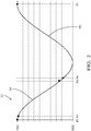
Figure 2 is a pumping cycle of a pressurising device offigure 1 . -
Figure 3 is a second embodiment of a pressurising device as per the invention. -
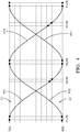
Figure 4 is a plot of two pumping cycles in opposition of phase as performed by said second embodiment offigure 3 . - In reference to the
figures 1 and2 , a diesel internal combustion engine provided with a directfuel injection equipment 6 is controlled by a command unit (ECU) 8. In use, diesel fuel stored in a tank at low pressure, or atmospheric pressure, is sent to apressurising device 10 comprising a digitalinlet metering valve 12, hereafterDIMV 12, and ahigh pressure pump 14. After being pressurised in saidpump 14, the fuel is delivered to a common rail then to fuel injectors, which along with the tank are drawn in dotted lines in the figures. - The
pump 14 comprises apumping head 16 and, upon command signals received from theECU 8 theDIMV 12 controls the upstream flow entering said pumpinghead 16. TheDIMV 12 is an electro actuated 2-way valve comprising an actuator such as a solenoid, controlling a valve member opening, or closing, the fuel entry into abuffer chamber 20 wherefrom said fuel is oriented toward thepumping head 16; said pumpinghead 16 performing a pumping cycle C1, shown infigure 2 , that is the alternation of a filling phase PF and of a compression phase PC. - In an alternative not shown, the
pump 14 comprises two or more pumping heads, all performing a pumping cycle in phase with each other. Thebuffer chamber 20 is, in this alternative, in fluid communication with all the pumping heads of thepump 14. - In the pumping
head 16, fuel is pressurised in a compression chamber 22 defined at the end of abore 24 in which apiston 26 urged by a rotatingcam 28 is reciprocally guided along a pumping axis X1. During the filling phase PF, when the piston moves from TDC (top dead center) to BDC (bottom dead center), pressure drops in said compression chamber 22 opening aninlet 32 by moving aninlet valve member 30. Fuel at low pressure is sucked through saidinlet 32 in said compression chamber 22. During the following compression phase PC when the piston moves from BDC to TDC, the pressure in said compression chamber 22 rises moving theinlet valve member 30 into a closed position of theinlet 32. The fuel is then pressurised in said compression chamber 22 prior to being expelled when said pressure overcomes a threshold forcing aoutlet valve member 34 to open anoutlet 36. - The figures show a single rotating cam urging the pistons but, in alternative embodiments, the
pump 14 may comprise several cams. - In a
multi-head pump 14, all heads being in phase and performing the same pumping cycle C1, thecam 28 is can be a multi-lobe cam and, the pumping axes are arranged to create the simultaneity of the pumping cycles. For instance, in a two head pump an elliptical cam having two lobes, may urge simultaneously two pistons opposed at 180° and, in a four head pump, a square came (with rounded corners) simultaneously urges four piston arranged at 90° from each other. - Typically, the
inlet valve members 30 is a passive valve moving under the influence of pressure difference between the compression chamber and the other side of the valve member, the inlet channel. In other alternatives, thevalve 30 can cooperate with an actuator, such as a solenoid, which advances the opening or retards the closing of the valve member. - Thanks to this arrangement, a
DIMV 12 controls the inlet to the pumping head. The following sequence, illustrated byfigure 2 where the cycle C1 starts with a filling phase PF describes steps of a method 100 executed by theECU 8 in order to control the fuel quantity compressed in the compression chamber. - The control method 100 comprises the following steps:
- receiving 110 signals enabling to determine the quantity of fuel required to be injected in the engine;
- computing 120 the duration that the
DIMV 12 needs to be in open state to enable said required quantity of fuel to enter thepump 14; - keeping 134 the
DIMV 12 in said open state when theinlet valve 30 opens; - switching 130 the
DIMV 12 to said open state when pumping cycle C1 initiates a filling phase PF; - switching 140 the
DIMV 12 to the closed state when the duration time has lapsed. - The steps of this method 100 are detailed in reference to
figure 2 where points are identified and commented: - Point P1
- ▪ the pumping cycle C1 is at TDC and, pressurised fuel is expelled out of the compression chamber 22,
- ▪ the
inlet 32 is closed, theoutlet 36 is open, - ▪ the
ECU 8 commands to open theDIMV 12 for the fuel to enter and fill thebuffer chamber 20.
- Point P2 just after point P1
- ▪ the cycle C1 starts a filling phase PF, the pressure in the compression chamber 22 starts to drop,
- ▪ the
inlet 32 opens enabling fuel in thebuffer chamber 20 to enter the compression chamber 22, - ▪ the
outlet 36 closes. - ▪ the
ECU 8 keeps the open command sent to theDIMV 12 for allowing fuel to flow through thebuffer chamber 20 and directly in the compression chamber 22.
- Point P3
- ▪ the pumping cycle C1 approaches the end of the filling phase PF,
- ▪ the
inlet 32 remains open, - ▪ the
outlet 36 remains closed, - ▪ as the duration computed at the method step 120 is reached, the
ECU 8 commands to close theDIMV 12 and, depending on pressure difference between thebuffer chamber 20 and the compression chamber 22, fuel in thebuffer chamber 20 continues, for a very short while, to enter the compression chamber 22.
- Point P4 just after point P3
- ▪ the pumping cycle C1 further approaches the end of the filling phase PF, the pressure in the compression chamber 22 is now superior to the pressure in the
buffer chamber 20, - ▪ the
inlet 32 closes and, theoutlet 36 remains closed, - ▪ the
DIMV 12 remains closed until the next filling phase starting with a new point P1.
- ▪ the pumping cycle C1 further approaches the end of the filling phase PF, the pressure in the compression chamber 22 is now superior to the pressure in the
- As can be followed through the pumping cycle and the sequence of points, the fuel enters the compression chamber as soon as the inlet valve opens at beginning of the filing phase PF and, when the
DIMV 12 closes the pressure difference between thebuffer chamber 20 and the compression chamber cancels very rapidly, this closing the inlet valve and ending said fuel entry right after closing theDIMV 12. The fuel quantity in the compression chamber is then controlled by closing theDIMV 12. - During a filling phase PF, the pressure drops in the compression chamber and:
- in a first step, at very beginning of said filling phase PF, the
DIMV 12 opens while the inlet is still closed. Fuel only enters and fills thebuffer chamber 20 wherein pressure rises; - in a subsequent second step said rising pressure in the buffer chamber overcomes said dropping pressure in the compression chamber and consequently the inlet opens. The
DIMV 12 remaining open, fuel in the buffer chamber enters the compression chamber and, a fuel flow can directly go through thechamber 20 in the compression chamber and, - in a final third step at completion of the computed opening duration of the
DIMV 12, the fuel quantity needed to match the engine demand has entered the compression chamber, theDIMV 12 closes, the pressure in thebuffer chamber 20 drops quickly and, this is immediately followed by closing of the inlet. - In reference to the
figures 3 and4 is presented a second embodiment of the invention wherein the pressurisingdevice 10 of thefuel injection equipment 6 comprises theDIMV 12, and a twin-head-pump 14. - To ease and simplify the description, numeral references previously used are kept for designating features having the same function, said features keeping their numeral references and may be now identified as "first".
- The twin-head-
pump 14 comprises thefirst pumping head 16, previously identified as the pumpinghead 16, and asecond pumping head 18. Upon command signals received from theECU 8, theDIMV 12 controls the upstream flow entering said two pumping heads 16, 18. TheDIMV 12 is an electro actuated 2-way valve comprising an actuator such as a solenoid controlling a valve member opening, or closing, the fuel entry into thebuffer chamber 20 wherefrom said fuel is oriented toward thefirst pumping head 16 performing the first pumping cycle C1 or, toward thesecond pumping head 18 performing a second pumping cycle C2. Each pumping cycle C1, C2 is the alternation of a filling phase PF and a compression phase PC and, in said twin-head-pump 14 the two cycles C1, C2 are in opposition of phase, the filling phase PF of a pumping head being simultaneous to the compression phase PC of the other pumping head. - In an alternative not shown, the
pump 14 is a multi-head pump comprising three, four or more pumping heads, some performing said first pumping cycle C1, the other performing the second pumping cycle C2 in opposition of phase with C1. In this alternative, thebuffer chamber 20 is in fluid communication with all the pumping heads of themulti-head pump 14. - The
first pumping head 16 is, as previously described, with the first compression chamber 22, thefirst bore 24, thefirst piston 26, the first pumping axis X1, the firstinlet valve member 30, thefirst inlet 32, the firstoutlet valve member 34 and thefirst outlet 36. - Similarly to the
first pumping head 16, in thesecond pumping head 18 fuel is pressurised in a second compression chamber 38 defined at the end of asecond bore 40 in which asecond piston 42 urged by said rotatingcam 28 is reciprocally guided along a second pumping axis X2. During the second filling phase PF2, when saidsecond piston 42 moves from TDC to BDC, pressure drops in said second compression chamber 38 moving a second inlet valve member 44 and opening a second inlet 46 through which fuel at low pressure is sucked in the second compression chamber 38. During the following second compression phase PC2 when the piston moves from BDC to TDC, the pressure in said second compression chamber 38 rises moving the second inlet valve member 46 into a closed position of the second inlet 46. The fuel is then pressurised in said second compression chamber 38 prior to being expelled when said pressure overcomes a threshold forcing a second outlet valve member 48 to open a second outlet 50. - As shown in
figure 3 , in a twin-head-pump 14 thecam 28 is typically a two-lobe cam opposed at 180°, as in an oval or elliptical shape and, the pumping axis X1, X2 are at 90° from each other. Said arrangement of cam profile and angled axis creates the opposition of phases although other arrangements, such as a one lobe cam and two pistons opposed at 180° or, pistons urged by different cams may achieve a similar result. - In a four-
head pump 14 not shown, a third head is opposed at 180° of thefirst head 16 and, a fourth head is opposed at 180° of thesecond head 18, thus the first and third heads performing the first cycle C1 and, the second and fourth heads performing the second cycle C2. - Typically, the first and second
inlet valve members 30, 44 are passive valves moving under the influence of difference between the pressure in the compression chamber and the pressure on the other side of the valve member. In other alternatives, thevalves 30, 44 can cooperate with an actuator, such as a solenoid, which advances the opening or retards the closing of the valve member. - Thanks to this arrangement, a
single DIMV 12 controls the inlet to the two pumping heads. The following sequence, illustrated infigure 4 where the first cycle C1 starts with a filling phase PF and the second cycle C2 starts with a compression phase PC, describes steps of the method 100 executed by theECU 8 in order to control the fuel quantity compressed in the two compression chambers. - The control method 100 comprises the following steps:
- receiving 110 signals enabling to determine the quantity of fuel required to be injected in the engine;
- computing 120 the duration that the
DIMV 12 needs to be in open state to enable said required quantity of fuel to enter the twin-head-pump 14; - keeping 134 the
DIMV 12 in said open state when either one of the first or second inlet valve opens 30, 44; - switching 130 the
DIMV 12 to said open state when either one of the pumping cycles C1, C2 initiates a filling phase PF; - switching 140 the
DIMV 12 to the closed state when the duration time has lapsed. - The steps of this method 100 are detailed in reference to
figure 4 where points are identified and commented: - Point P1
- ▪ the first cycle C1 is at TDC and, pressurised fuel is expelled out of the first compression chamber 22,
- ▪ the
first inlet 32 is closed, thefirst outlet 36 is open, - ▪ the second cycle C2 is at BDC and, the second compression chamber 38 is filled with fuel at low pressure,
- ▪ the second inlet 46 is closed and, the second outlet 50 is closed,
- ▪ the
ECU 8 commands to open theDIMV 12 for the fuel to enter and to fill thebuffer chamber 20.
- Point P2 just after point P1
- ▪ the first cycle starts a filling phase PF, the pressure in the first compression chamber 22 drops,
- ▪ the
first inlet 32 opens enabling fuel in thebuffer chamber 20 to enter the first compression chamber 22, - ▪ the
first outlet 36 closes. - ▪ the second cycle starts a compression phase PC, the pressure in the second compression chamber 38 starts to rise,
- ▪ the second inlet 46 remains closed, the second outlet 50 remains closed,
- ▪ the
ECU 8 maintains the open command sent to theDIMV 12 for allowing fuel to flow through thebuffer chamber 20 and directly in the first compression chamber 22.
- Point P3
- ▪ the first cycle approaches the end of the filling phase PF,
- ▪ the
first inlet 32 remains open and, thefirst outlet 36 remains closed, - ▪ the second cycle C2 approaches the end of the compression phase PC, the pressure in the second compression chamber 38 continues to rise,
- ▪ the second inlet 46 remains closed, the second outlet 50 remains closed,
- ▪ the
ECU 8 commands to close theDIMV 12 and, depending on pressure difference between thebuffer chamber 20 and the first compression chamber 22, fuel in thebuffer chamber 20 continues, for a short while, to enter the first compression chamber 22.
- Point P4 just after point P3
- ▪ the first cycle C1 further approaches the end of the filling phase PF, the pressure in the first compression chamber 22 is now superior to the pressure in the
buffer chamber 20, - ▪ the
first inlet 32 closes and, thefirst outlet 36 remains closed, - ▪ the second cycle C2 further approaches the end of the compression phase PC, the pressure in the second compression chamber 38 continues to rise,
- ▪ the second inlet 46 remains closed, the second outlet 50 remains closed,
- ▪ the
DIMV 12 remains closed.
- ▪ the first cycle C1 further approaches the end of the filling phase PF, the pressure in the first compression chamber 22 is now superior to the pressure in the
- Point P5
- ▪ the first cycle is at BDC, the first compression chamber 22 is now filled with low pressure fuel,
- ▪ the
first inlet 32 remains closed, thefirst outlet 36 remains closed, - ▪ the second cycle is at TDC, the pressure in the second compression chamber 38 is maximum,
- ▪ the second inlet 46 is closed and, the second outlet 50 opens to expel pressurised fuel out of the second compression chamber 38,
- ▪ the
ECU 8 commands to open theDIMV 12 for the fuel to enter thebuffer chamber 20.
- Point P6 soon after point P5
- ▪ the first cycle C1 starts a compression phase PC, the pressure in the first compression chamber 22 starts to rise,
- ▪ the
first inlet 32 remains closed, thefirst outlet 36 remains closed. - ▪ the second cycle C2 starts a filling phase PF, the pressure in the second compression chamber 38 starts to drop,
- ▪ the second inlet 46 opens to enable fuel in the
buffer chamber 20 to enter the second compression chamber 38 and, the second outlet 50 closes, - ▪ the
ECU 8 keeps the open command sent to theDIMV 12 for allowing fuel to flow through thebuffer chamber 20 and directly in the second compression chamber 38.
- Point P7
- ▪ the first cycle approaches the end of the compression phase PC, the pressure in the first compression chamber 22 continues to rise,
- ▪ the
first inlet 32 remains closed, thefirst outlet 36 remains closed, - ▪ the second cycle approaches the end of the filling phase PF,
- ▪ the second inlet 46 remains open and, the second outlet 50 remains closed,
- ▪ the
ECU 8 commands to close theDIMV 12 and, depending on pressure difference between thebuffer chamber 20 and the second compression chamber 38, fuel in thebuffer chamber 20 continues, for a short while, to enter the second compression chamber 38.
- Point P8 just after point P7
- ▪ the first cycle further approaches the end of the compression phase PC,
- ▪ the
first inlet 32 remains closed, thefirst outlet 36 remains closed, - ▪ the second cycle further approaches the end of the filling phase PF, the pressure in the second compression chamber 38 is now superior to the pressure in the
buffer chamber 20, - ▪ the second inlet 46 closes and, the second outlet 50 remains closed,
- ▪ the
DIMV 12 remains closed.
- As can be followed through the pumping cycles and the sequence of points, the fuel enters the compression chamber as soon as the inlet valve member opens at beginning of the filing phase PF and, later in said phase when the
DIMV 12 closes the pressure difference between thebuffer chamber 20 and the compression chamber cancels which closes the inlet valve member right after theDIMV 12 closes, ending said fuel entry. The fuel quantity in the compression chamber is then controlled by closing theDIMV 12. - Thanks to this arrangement a
single DIMV 12 andbuffer chamber 20 serve two pumping head. - Similarly to the first embodiment, during a filling phase, pressure drops in the compression chamber and:
- in a first step, at very beginning of said filling phase PF, the
DIMV 12 opens while all inlets are closed. Fuel can only enter and fill thebuffer chamber 20 wherein pressure rises; - in a subsequent second step said rising pressure in the buffer chamber overcomes said dropping pressure in the compression chamber consequently opening the inlet and, the
DIMV 12 remaining open, fuel in the buffer chamber enters the compression chamber and, a fuel flow can directly go through thebuffer chamber 20 in the compression chamber and, - in a final third step at completion of the computed opening duration of the
DIMV 12, the fuel quantity needed to match the engine demand has entered the compression chamber, theDIMV 12 closes, the pressure in thebuffer chamber 20 drops quickly and, this is immediately followed by closing of the inlet. -
- TDC
- top dead center
- BDC
- bottom dead center
- X1
- first pumping axis
- X2
- second pumping axis
- C1
- first pumping cycle
- PF1
- filling phase of the first pumping cycle
- PC1
- compression phase of the first pumping cycle
- C2
- second pumping cycle
- PF2
- filling phase of the second pumping cycle
- PC2
- compression phase of the second pumping cycle
- P1 - P8
- points
- 6
- fuel injection equipment
- 8
- command unit - ECU
- 10
- pressurising device
- 12
- digital inlet metering valve - DIMV
- 14
- pump - twin-head-pump
- 16
- first pumping head
- 18
- second pumping head
- 20
- buffer chamber
- 22
- first compression chamber
- 24
- first bore
- 26
- first piston
- 28
- cam
- 30
- first inlet valve member
- 32
- first inlet
- 34
- first outlet valve member
- 36
- first outlet
- 38
- second compression chamber
- 40
- second bore
- 42
- second piston
- 44
- second inlet valve member
- 46
- second inlet
- 48
- second outlet valve member
50 second outlet
100 method
110 receiving signals
120 computing
130 switching to open
134 keeping open - 140
- switching to close
Claims (13)
- Pressurising device (10) of a direct fuel injection equipment (FIE) of a diesel internal combustion engine, said pressurising device (10) comprising a digital inlet metering valve (DIMV, 12) controlling an inlet fluid communication to a pump (14) performing, in use, a pumping cycle (C1) in a pumping head (16), said cycle (C1) being the alternation of a filling phase (PF) and a compression phase (PC) and wherein, the DIMV (12) switches to an open state after said cycle (C1) initiates a filling phase (PF) and, switches to a closed state when approaching the end of said filling phase;
and wherein,
the pump (14) comprises:- the pumping head (16) defining a compression chamber (22) having an inlet (32) controlled by an inlet valve (30) and an outlet (36) controlled by an outlet valve (34) and, a piston (26) reciprocally moving, in use, between BDC and TDC along a pumping axis (X1) to perform said pumping cycle (C1);and wherein,
the digital inlet metering valve (DIMV) (12) comprises an electro 2-way valve controlling the inlet into a buffer chamber (20) connected to the inlet (32). - Pressurising unit (10) as claimed in the preceding claim wherein the DIMV (12) and the pump (14) are integrated in a single housing forming in compact assembly of the FIE.
- Pressurising unit (10) as claimed in any one of the preceding claims wherein, in use, in open state of the DIMV (12) the fuel fills said buffer chamber (20) and from there fills the compression chamber (22) of the pumping head (16) that is in filling phase (PF) and which volume increases.
- Pressurising unit (10) as claimed in claim 1, wherein the pump (14) is a twin-head-pump (14) performing, in use, said first pumping cycle (C1) in said first pumping head (16) and, a second pumping cycle (C2) in a second pumping head (18), said cycles (C1, C2) being the alternation of a filling phase (PF) and a compression phase (PC), said first (C1) and second (C2) cycles being in opposition of phase of one another so that, the compression phase (PC) of a cycle is simultaneous to the filling phase (PF) of the other cycle, and wherein, the DIMV (12) controls the inlet fluid communication to said twin-head-pump (14) and it switches to an open state after either cycle (C1, C2) initiates a filling phase (PF) and, switches to a closed state when approaching the end of said filling phase.
- Pressurising unit (10) as claimed in claim 4 wherein the DIMV (12) and the twin-head-pump (14) are integrated in a single housing forming in compact assembly of the FIE.
- Pressurising unit (10) as claimed in any claims 4 or 5 wherein, in use, low pressure fuel exiting the DIMV (12) is delivered to the twin-head-pump (14) wherein it is compressed in the first pumping cycle (C1) or in the second pumping cycle (C2).
- Pressurising unit (10) as claimed in any of the claims 4 to 6 wherein the twin-head-pump (14) comprises:- the first pumping head (16) defining a first compression chamber (22) having a first inlet (32) controlled by a first inlet valve (30) and a first outlet (36) controlled by a first outlet valve (34) and, a first piston (26) reciprocally moving, in use, between BDC and TDC along a first axis (X1) to perform said first pumping cycle (C1);- the second pumping head (18) defining a second compression chamber (38) having a second inlet (46) controlled by a second inlet valve (44) and a second outlet (50) controlled by a second outlet valve (48) and, a second piston (42) reciprocally moving, in use, between BDC and TDC along a second axis (X2) to perform said second pumping cycle (C2) and wherein,the digital inlet metering valve (DIMV) (12) comprises an electro 2-way valve controlling the inlet into a buffer chamber (20) connected to the first inlet (32) and to the second inlet (46).
- Pressurising unit (10) as claimed in claim 7 wherein, in use, in open state of the DIMV (12) the fuel fills said buffer chamber (20) and from there fills the compression chamber (22, 38) of the pumping head (16, 18) that is in filling phase (PF) and which volume increases.
- Fuel injection equipment (6) for a diesel internal combustion engine, said FIE comprising a pressurising unit (10) as claimed in any one of the preceding claims.
- Control method (100) of a fuel injection equipment (6) as claimed in claim 9, the method comprising the following steps:- receiving (110) signals enabling to determine the quantity of fuel required to be injected in the engine;- computing (120) the duration that the DIMV (12) needs to be in open state to enable said required quantity of fuel to enter the pump (14);- switching (130) the DIMV (12) to said open state after the pumping cycle (C1) initiates a filling phase (PF);- switching (140) the DIMV (12) to the closed state when the duration time has lapsed and,wherein the step switching (130) the DIMV (12) to an open state enables fuel to fill the buffer chamber (20) when the pumping cycle (C1) initiates a filling phase (PF), the inlet valves (30) being closed preventing fuel entry into the compression chamber then, subsequent to said switching step (130), the method (100) comprises the step- keeping (134) the DIMV (12) in said open state when the inlet valve opens (30).
- Control method (100) as claimed in claim 10, the fuel injection equipment being as claimed in claim 4, the method comprising the following steps:- computing (120) the duration that the DIMV (12) needs to be in open state to enable said required quantity of fuel to enter the twin-head-pump (14);- switching (130) the DIMV (12) to said open state when either one of the pumping cycles (C1, C2) initiates a filling phase (PF);- switching (140) the DIMV (12) to the closed state when the duration time has lapsed.
- Control method (100) as claimed in claim 11, the pressurising device (10) being as claimed in either of the claims 7 or 8, wherein the step switching (130) the DIMV (12) to an open state enables fuel to fill the buffer chamber (20) when either of the pumping cycles (C1, C2) initiates a filling phase (PF), both first and second inlet valves (30, 44) being closed preventing fuel entry into the compression chambers then, subsequent to said switching step (130), the method (100) comprises the step- keeping (134) the DIMV (12) in said open state when either one of the first or second inlet valve opens (30, 44).
- Electronic command unit (8) adapted execute a method (100) as claimed in any one of the claims 10 to 12.
Applications Claiming Priority (1)
| Application Number | Priority Date | Filing Date | Title |
|---|---|---|---|
| GB1712342.3A GB2565093B (en) | 2017-08-01 | 2017-08-01 | Fuel Pressurising device |
Publications (2)
| Publication Number | Publication Date |
|---|---|
| EP3438445A1 true EP3438445A1 (en) | 2019-02-06 |
| EP3438445B1 EP3438445B1 (en) | 2023-10-25 |
Family
ID=59778957
Family Applications (1)
| Application Number | Title | Priority Date | Filing Date |
|---|---|---|---|
| EP18183555.4A Active EP3438445B1 (en) | 2017-08-01 | 2018-07-13 | Fuel pressurising device |
Country Status (2)
| Country | Link |
|---|---|
| EP (1) | EP3438445B1 (en) |
| GB (1) | GB2565093B (en) |
Citations (5)
| Publication number | Priority date | Publication date | Assignee | Title |
|---|---|---|---|---|
| EP0816672A2 (en) * | 1996-07-05 | 1998-01-07 | Nippon Soken, Inc. | High-pressure pump for use in fuel injection system for diesel engine |
| EP0902181A2 (en) * | 1997-09-11 | 1999-03-17 | Denso Corporation | Variable-discharge-rate high-pressure pump |
| US20060000447A1 (en) * | 2004-06-30 | 2006-01-05 | C.R.F. Societa Consortile Per Azioni | High-pressure variable-flow-rate pump for a fuel-injection system |
| EP2050952A1 (en) * | 2007-10-16 | 2009-04-22 | Delphi Technologies, Inc. | Fuel pump |
| EP2647824A1 (en) * | 2012-04-05 | 2013-10-09 | Delphi Technologies Holding S.à.r.l. | Injection pump systems and methods of operation |
Family Cites Families (3)
| Publication number | Priority date | Publication date | Assignee | Title |
|---|---|---|---|---|
| JP2002098021A (en) * | 2000-09-25 | 2002-04-05 | Toyota Motor Corp | Compound solenoid valve, high pressure pump and high pressure pump controller |
| DE102008043237A1 (en) * | 2008-10-28 | 2010-04-29 | Robert Bosch Gmbh | High-pressure fuel pump for an internal combustion engine |
| WO2016177431A1 (en) * | 2015-05-07 | 2016-11-10 | Volvo Truck Corporation | Fuel pump assembly |
-
2017
- 2017-08-01 GB GB1712342.3A patent/GB2565093B/en active Active
-
2018
- 2018-07-13 EP EP18183555.4A patent/EP3438445B1/en active Active
Patent Citations (5)
| Publication number | Priority date | Publication date | Assignee | Title |
|---|---|---|---|---|
| EP0816672A2 (en) * | 1996-07-05 | 1998-01-07 | Nippon Soken, Inc. | High-pressure pump for use in fuel injection system for diesel engine |
| EP0902181A2 (en) * | 1997-09-11 | 1999-03-17 | Denso Corporation | Variable-discharge-rate high-pressure pump |
| US20060000447A1 (en) * | 2004-06-30 | 2006-01-05 | C.R.F. Societa Consortile Per Azioni | High-pressure variable-flow-rate pump for a fuel-injection system |
| EP2050952A1 (en) * | 2007-10-16 | 2009-04-22 | Delphi Technologies, Inc. | Fuel pump |
| EP2647824A1 (en) * | 2012-04-05 | 2013-10-09 | Delphi Technologies Holding S.à.r.l. | Injection pump systems and methods of operation |
Also Published As
| Publication number | Publication date |
|---|---|
| GB2565093B (en) | 2020-03-25 |
| GB2565093A (en) | 2019-02-06 |
| GB201712342D0 (en) | 2017-09-13 |
| EP3438445B1 (en) | 2023-10-25 |
Similar Documents
| Publication | Publication Date | Title |
|---|---|---|
| US5230613A (en) | Common rail fuel injection system | |
| US4628881A (en) | Pressure-controlled fuel injection for internal combustion engines | |
| USRE33270E (en) | Pressure-controlled fuel injection for internal combustion engines | |
| US5133645A (en) | Common rail fuel injection system | |
| US6843053B2 (en) | Fuel system | |
| US9157402B2 (en) | Multi-valve fuel injection system and injection method | |
| US4471740A (en) | Premetered pump injector having constant injection pressure, and derivative system | |
| US4184459A (en) | Fuel injection system for internal combustion engine | |
| US9447740B2 (en) | Engine system having hydraulically actuated gas injector | |
| US7198034B2 (en) | Method and system for the direct injection of fuel into an internal combustion engine | |
| JPS6134345A (en) | Fuel pump device | |
| EP1612402A1 (en) | A high-pressure variable-flow-rate pump for a fuel-injection system | |
| EP0107894B1 (en) | Method and apparatus for precisely controlled fuel injection in a diesel engine | |
| US7063073B2 (en) | Method for the direct injection of fuel into an internal combustion engine | |
| CN1873213B (en) | Fuel injector control system and method | |
| US5458103A (en) | Fuel injection arrangement for internal combustion engines | |
| EP3438445B1 (en) | Fuel pressurising device | |
| US20060169250A1 (en) | Method, computer program, and control and/or regulating unit for operating an internal | |
| US5377636A (en) | Solenoid operated pump-line-nozzle fuel injection system and inline pump therefor | |
| US7017554B2 (en) | Fuel supply device of an internal combustion engine | |
| US5333588A (en) | Pump/injector | |
| US10830194B2 (en) | Common rail fuel system having pump-accumulator injectors | |
| CN1329654C (en) | Fuel injection devices for internal combustion engines | |
| EP1657434A1 (en) | A high-pressure pump with a device for regulating the flow rate for a fuel-injection system | |
| RU2230213C2 (en) | Automobile diesel engine high-pressure fuel-injection pump |
Legal Events
| Date | Code | Title | Description |
|---|---|---|---|
| PUAI | Public reference made under article 153(3) epc to a published international application that has entered the european phase |
Free format text: ORIGINAL CODE: 0009012 |
|
| STAA | Information on the status of an ep patent application or granted ep patent |
Free format text: STATUS: THE APPLICATION HAS BEEN PUBLISHED |
|
| AK | Designated contracting states |
Kind code of ref document: A1 Designated state(s): AL AT BE BG CH CY CZ DE DK EE ES FI FR GB GR HR HU IE IS IT LI LT LU LV MC MK MT NL NO PL PT RO RS SE SI SK SM TR |
|
| AX | Request for extension of the european patent |
Extension state: BA ME |
|
| STAA | Information on the status of an ep patent application or granted ep patent |
Free format text: STATUS: REQUEST FOR EXAMINATION WAS MADE |
|
| 17P | Request for examination filed |
Effective date: 20190806 |
|
| RBV | Designated contracting states (corrected) |
Designated state(s): AL AT BE BG CH CY CZ DE DK EE ES FI FR GB GR HR HU IE IS IT LI LT LU LV MC MK MT NL NO PL PT RO RS SE SI SK SM TR |
|
| STAA | Information on the status of an ep patent application or granted ep patent |
Free format text: STATUS: EXAMINATION IS IN PROGRESS |
|
| 17Q | First examination report despatched |
Effective date: 20200227 |
|
| GRAP | Despatch of communication of intention to grant a patent |
Free format text: ORIGINAL CODE: EPIDOSNIGR1 |
|
| STAA | Information on the status of an ep patent application or granted ep patent |
Free format text: STATUS: GRANT OF PATENT IS INTENDED |
|
| INTG | Intention to grant announced |
Effective date: 20230517 |
|
| P01 | Opt-out of the competence of the unified patent court (upc) registered |
Effective date: 20230327 |
|
| RAP3 | Party data changed (applicant data changed or rights of an application transferred) |
Owner name: DELPHI TECHNOLOGIES IP LIMITED |
|
| GRAS | Grant fee paid |
Free format text: ORIGINAL CODE: EPIDOSNIGR3 |
|
| GRAA | (expected) grant |
Free format text: ORIGINAL CODE: 0009210 |
|
| STAA | Information on the status of an ep patent application or granted ep patent |
Free format text: STATUS: THE PATENT HAS BEEN GRANTED |
|
| AK | Designated contracting states |
Kind code of ref document: B1 Designated state(s): AL AT BE BG CH CY CZ DE DK EE ES FI FR GB GR HR HU IE IS IT LI LT LU LV MC MK MT NL NO PL PT RO RS SE SI SK SM TR |
|
| REG | Reference to a national code |
Ref country code: GB Ref legal event code: FG4D |
|
| REG | Reference to a national code |
Ref country code: CH Ref legal event code: EP |
|
| REG | Reference to a national code |
Ref country code: DE Ref legal event code: R096 Ref document number: 602018059840 Country of ref document: DE |
|
| REG | Reference to a national code |
Ref country code: IE Ref legal event code: FG4D |
|
| REG | Reference to a national code |
Ref country code: LT Ref legal event code: MG9D |
|
| REG | Reference to a national code |
Ref country code: NL Ref legal event code: MP Effective date: 20231025 |
|
| REG | Reference to a national code |
Ref country code: AT Ref legal event code: MK05 Ref document number: 1624890 Country of ref document: AT Kind code of ref document: T Effective date: 20231025 |
|
| PG25 | Lapsed in a contracting state [announced via postgrant information from national office to epo] |
Ref country code: NL Free format text: LAPSE BECAUSE OF FAILURE TO SUBMIT A TRANSLATION OF THE DESCRIPTION OR TO PAY THE FEE WITHIN THE PRESCRIBED TIME-LIMIT Effective date: 20231025 |
|
| PG25 | Lapsed in a contracting state [announced via postgrant information from national office to epo] |
Ref country code: GR Free format text: LAPSE BECAUSE OF FAILURE TO SUBMIT A TRANSLATION OF THE DESCRIPTION OR TO PAY THE FEE WITHIN THE PRESCRIBED TIME-LIMIT Effective date: 20240126 |
|
| PG25 | Lapsed in a contracting state [announced via postgrant information from national office to epo] |
Ref country code: IS Free format text: LAPSE BECAUSE OF FAILURE TO SUBMIT A TRANSLATION OF THE DESCRIPTION OR TO PAY THE FEE WITHIN THE PRESCRIBED TIME-LIMIT Effective date: 20240225 |
|
| PG25 | Lapsed in a contracting state [announced via postgrant information from national office to epo] |
Ref country code: LT Free format text: LAPSE BECAUSE OF FAILURE TO SUBMIT A TRANSLATION OF THE DESCRIPTION OR TO PAY THE FEE WITHIN THE PRESCRIBED TIME-LIMIT Effective date: 20231025 |
|
| PG25 | Lapsed in a contracting state [announced via postgrant information from national office to epo] |
Ref country code: AT Free format text: LAPSE BECAUSE OF FAILURE TO SUBMIT A TRANSLATION OF THE DESCRIPTION OR TO PAY THE FEE WITHIN THE PRESCRIBED TIME-LIMIT Effective date: 20231025 |
|
| PG25 | Lapsed in a contracting state [announced via postgrant information from national office to epo] |
Ref country code: ES Free format text: LAPSE BECAUSE OF FAILURE TO SUBMIT A TRANSLATION OF THE DESCRIPTION OR TO PAY THE FEE WITHIN THE PRESCRIBED TIME-LIMIT Effective date: 20231025 |
|
| PG25 | Lapsed in a contracting state [announced via postgrant information from national office to epo] |
Ref country code: LT Free format text: LAPSE BECAUSE OF FAILURE TO SUBMIT A TRANSLATION OF THE DESCRIPTION OR TO PAY THE FEE WITHIN THE PRESCRIBED TIME-LIMIT Effective date: 20231025 Ref country code: IS Free format text: LAPSE BECAUSE OF FAILURE TO SUBMIT A TRANSLATION OF THE DESCRIPTION OR TO PAY THE FEE WITHIN THE PRESCRIBED TIME-LIMIT Effective date: 20240225 Ref country code: GR Free format text: LAPSE BECAUSE OF FAILURE TO SUBMIT A TRANSLATION OF THE DESCRIPTION OR TO PAY THE FEE WITHIN THE PRESCRIBED TIME-LIMIT Effective date: 20240126 Ref country code: ES Free format text: LAPSE BECAUSE OF FAILURE TO SUBMIT A TRANSLATION OF THE DESCRIPTION OR TO PAY THE FEE WITHIN THE PRESCRIBED TIME-LIMIT Effective date: 20231025 Ref country code: BG Free format text: LAPSE BECAUSE OF FAILURE TO SUBMIT A TRANSLATION OF THE DESCRIPTION OR TO PAY THE FEE WITHIN THE PRESCRIBED TIME-LIMIT Effective date: 20240125 Ref country code: AT Free format text: LAPSE BECAUSE OF FAILURE TO SUBMIT A TRANSLATION OF THE DESCRIPTION OR TO PAY THE FEE WITHIN THE PRESCRIBED TIME-LIMIT Effective date: 20231025 Ref country code: PT Free format text: LAPSE BECAUSE OF FAILURE TO SUBMIT A TRANSLATION OF THE DESCRIPTION OR TO PAY THE FEE WITHIN THE PRESCRIBED TIME-LIMIT Effective date: 20240226 |
|
| RAP2 | Party data changed (patent owner data changed or rights of a patent transferred) |
Owner name: PHINIA DELPHI LUXEMBOURG SARL |
|
| PG25 | Lapsed in a contracting state [announced via postgrant information from national office to epo] |
Ref country code: SE Free format text: LAPSE BECAUSE OF FAILURE TO SUBMIT A TRANSLATION OF THE DESCRIPTION OR TO PAY THE FEE WITHIN THE PRESCRIBED TIME-LIMIT Effective date: 20231025 Ref country code: RS Free format text: LAPSE BECAUSE OF FAILURE TO SUBMIT A TRANSLATION OF THE DESCRIPTION OR TO PAY THE FEE WITHIN THE PRESCRIBED TIME-LIMIT Effective date: 20231025 Ref country code: PL Free format text: LAPSE BECAUSE OF FAILURE TO SUBMIT A TRANSLATION OF THE DESCRIPTION OR TO PAY THE FEE WITHIN THE PRESCRIBED TIME-LIMIT Effective date: 20231025 Ref country code: NO Free format text: LAPSE BECAUSE OF FAILURE TO SUBMIT A TRANSLATION OF THE DESCRIPTION OR TO PAY THE FEE WITHIN THE PRESCRIBED TIME-LIMIT Effective date: 20240125 Ref country code: LV Free format text: LAPSE BECAUSE OF FAILURE TO SUBMIT A TRANSLATION OF THE DESCRIPTION OR TO PAY THE FEE WITHIN THE PRESCRIBED TIME-LIMIT Effective date: 20231025 Ref country code: HR Free format text: LAPSE BECAUSE OF FAILURE TO SUBMIT A TRANSLATION OF THE DESCRIPTION OR TO PAY THE FEE WITHIN THE PRESCRIBED TIME-LIMIT Effective date: 20231025 |
|
| PG25 | Lapsed in a contracting state [announced via postgrant information from national office to epo] |
Ref country code: DK Free format text: LAPSE BECAUSE OF FAILURE TO SUBMIT A TRANSLATION OF THE DESCRIPTION OR TO PAY THE FEE WITHIN THE PRESCRIBED TIME-LIMIT Effective date: 20231025 |
|
| PG25 | Lapsed in a contracting state [announced via postgrant information from national office to epo] |
Ref country code: CZ Free format text: LAPSE BECAUSE OF FAILURE TO SUBMIT A TRANSLATION OF THE DESCRIPTION OR TO PAY THE FEE WITHIN THE PRESCRIBED TIME-LIMIT Effective date: 20231025 |
|
| REG | Reference to a national code |
Ref country code: DE Ref legal event code: R097 Ref document number: 602018059840 Country of ref document: DE |
|
| PG25 | Lapsed in a contracting state [announced via postgrant information from national office to epo] |
Ref country code: SK Free format text: LAPSE BECAUSE OF FAILURE TO SUBMIT A TRANSLATION OF THE DESCRIPTION OR TO PAY THE FEE WITHIN THE PRESCRIBED TIME-LIMIT Effective date: 20231025 |
|
| PG25 | Lapsed in a contracting state [announced via postgrant information from national office to epo] |
Ref country code: SM Free format text: LAPSE BECAUSE OF FAILURE TO SUBMIT A TRANSLATION OF THE DESCRIPTION OR TO PAY THE FEE WITHIN THE PRESCRIBED TIME-LIMIT Effective date: 20231025 Ref country code: SK Free format text: LAPSE BECAUSE OF FAILURE TO SUBMIT A TRANSLATION OF THE DESCRIPTION OR TO PAY THE FEE WITHIN THE PRESCRIBED TIME-LIMIT Effective date: 20231025 Ref country code: RO Free format text: LAPSE BECAUSE OF FAILURE TO SUBMIT A TRANSLATION OF THE DESCRIPTION OR TO PAY THE FEE WITHIN THE PRESCRIBED TIME-LIMIT Effective date: 20231025 Ref country code: IT Free format text: LAPSE BECAUSE OF FAILURE TO SUBMIT A TRANSLATION OF THE DESCRIPTION OR TO PAY THE FEE WITHIN THE PRESCRIBED TIME-LIMIT Effective date: 20231025 Ref country code: EE Free format text: LAPSE BECAUSE OF FAILURE TO SUBMIT A TRANSLATION OF THE DESCRIPTION OR TO PAY THE FEE WITHIN THE PRESCRIBED TIME-LIMIT Effective date: 20231025 Ref country code: DK Free format text: LAPSE BECAUSE OF FAILURE TO SUBMIT A TRANSLATION OF THE DESCRIPTION OR TO PAY THE FEE WITHIN THE PRESCRIBED TIME-LIMIT Effective date: 20231025 Ref country code: CZ Free format text: LAPSE BECAUSE OF FAILURE TO SUBMIT A TRANSLATION OF THE DESCRIPTION OR TO PAY THE FEE WITHIN THE PRESCRIBED TIME-LIMIT Effective date: 20231025 |
|
| PLBE | No opposition filed within time limit |
Free format text: ORIGINAL CODE: 0009261 |
|
| STAA | Information on the status of an ep patent application or granted ep patent |
Free format text: STATUS: NO OPPOSITION FILED WITHIN TIME LIMIT |
|
| 26N | No opposition filed |
Effective date: 20240726 |
|
| REG | Reference to a national code |
Ref country code: GB Ref legal event code: 732E Free format text: REGISTERED BETWEEN 20240919 AND 20240925 |
|
| PG25 | Lapsed in a contracting state [announced via postgrant information from national office to epo] |
Ref country code: SI Free format text: LAPSE BECAUSE OF FAILURE TO SUBMIT A TRANSLATION OF THE DESCRIPTION OR TO PAY THE FEE WITHIN THE PRESCRIBED TIME-LIMIT Effective date: 20231025 |
|
| PG25 | Lapsed in a contracting state [announced via postgrant information from national office to epo] |
Ref country code: SI Free format text: LAPSE BECAUSE OF FAILURE TO SUBMIT A TRANSLATION OF THE DESCRIPTION OR TO PAY THE FEE WITHIN THE PRESCRIBED TIME-LIMIT Effective date: 20231025 |
|
| PG25 | Lapsed in a contracting state [announced via postgrant information from national office to epo] |
Ref country code: MC Free format text: LAPSE BECAUSE OF FAILURE TO SUBMIT A TRANSLATION OF THE DESCRIPTION OR TO PAY THE FEE WITHIN THE PRESCRIBED TIME-LIMIT Effective date: 20231025 |
|
| REG | Reference to a national code |
Ref country code: CH Ref legal event code: PL |
|
| PG25 | Lapsed in a contracting state [announced via postgrant information from national office to epo] |
Ref country code: LU Free format text: LAPSE BECAUSE OF NON-PAYMENT OF DUE FEES Effective date: 20240713 |
|
| PG25 | Lapsed in a contracting state [announced via postgrant information from national office to epo] |
Ref country code: LU Free format text: LAPSE BECAUSE OF NON-PAYMENT OF DUE FEES Effective date: 20240713 |
|
| PG25 | Lapsed in a contracting state [announced via postgrant information from national office to epo] |
Ref country code: CH Free format text: LAPSE BECAUSE OF NON-PAYMENT OF DUE FEES Effective date: 20240731 Ref country code: BE Free format text: LAPSE BECAUSE OF NON-PAYMENT OF DUE FEES Effective date: 20240731 |
|
| REG | Reference to a national code |
Ref country code: BE Ref legal event code: MM Effective date: 20240731 |
|
| PGFP | Annual fee paid to national office [announced via postgrant information from national office to epo] |
Ref country code: GB Payment date: 20250612 Year of fee payment: 8 |
|
| PGFP | Annual fee paid to national office [announced via postgrant information from national office to epo] |
Ref country code: FR Payment date: 20250612 Year of fee payment: 8 |
|
| PG25 | Lapsed in a contracting state [announced via postgrant information from national office to epo] |
Ref country code: IE Free format text: LAPSE BECAUSE OF NON-PAYMENT OF DUE FEES Effective date: 20240713 |
|
| PG25 | Lapsed in a contracting state [announced via postgrant information from national office to epo] |
Ref country code: FI Free format text: LAPSE BECAUSE OF FAILURE TO SUBMIT A TRANSLATION OF THE DESCRIPTION OR TO PAY THE FEE WITHIN THE PRESCRIBED TIME-LIMIT Effective date: 20231025 |
|
| PGFP | Annual fee paid to national office [announced via postgrant information from national office to epo] |
Ref country code: DE Payment date: 20250616 Year of fee payment: 8 |
|
| PG25 | Lapsed in a contracting state [announced via postgrant information from national office to epo] |
Ref country code: CY Free format text: LAPSE BECAUSE OF FAILURE TO SUBMIT A TRANSLATION OF THE DESCRIPTION OR TO PAY THE FEE WITHIN THE PRESCRIBED TIME-LIMIT; INVALID AB INITIO Effective date: 20180713 |
|
| PG25 | Lapsed in a contracting state [announced via postgrant information from national office to epo] |
Ref country code: HU Free format text: LAPSE BECAUSE OF FAILURE TO SUBMIT A TRANSLATION OF THE DESCRIPTION OR TO PAY THE FEE WITHIN THE PRESCRIBED TIME-LIMIT; INVALID AB INITIO Effective date: 20180713 |