EP3438350B1 - Subsea deployment monitoring system - Google Patents
Subsea deployment monitoring system Download PDFInfo
- Publication number
- EP3438350B1 EP3438350B1 EP18187216.9A EP18187216A EP3438350B1 EP 3438350 B1 EP3438350 B1 EP 3438350B1 EP 18187216 A EP18187216 A EP 18187216A EP 3438350 B1 EP3438350 B1 EP 3438350B1
- Authority
- EP
- European Patent Office
- Prior art keywords
- structural casing
- tool
- subsea
- sensor system
- casing
- Prior art date
- Legal status (The legal status is an assumption and is not a legal conclusion. Google has not performed a legal analysis and makes no representation as to the accuracy of the status listed.)
- Active
Links
Images

Classifications
-
- E—FIXED CONSTRUCTIONS
- E21—EARTH OR ROCK DRILLING; MINING
- E21B—EARTH OR ROCK DRILLING; OBTAINING OIL, GAS, WATER, SOLUBLE OR MELTABLE MATERIALS OR A SLURRY OF MINERALS FROM WELLS
- E21B47/00—Survey of boreholes or wells
- E21B47/001—Survey of boreholes or wells for underwater installation
-
- E—FIXED CONSTRUCTIONS
- E21—EARTH OR ROCK DRILLING; MINING
- E21B—EARTH OR ROCK DRILLING; OBTAINING OIL, GAS, WATER, SOLUBLE OR MELTABLE MATERIALS OR A SLURRY OF MINERALS FROM WELLS
- E21B23/00—Apparatus for displacing, setting, locking, releasing or removing tools, packers or the like in boreholes or wells
-
- E—FIXED CONSTRUCTIONS
- E21—EARTH OR ROCK DRILLING; MINING
- E21B—EARTH OR ROCK DRILLING; OBTAINING OIL, GAS, WATER, SOLUBLE OR MELTABLE MATERIALS OR A SLURRY OF MINERALS FROM WELLS
- E21B19/00—Handling rods, casings, tubes or the like outside the borehole, e.g. in the derrick; Apparatus for feeding the rods or cables
- E21B19/002—Handling rods, casings, tubes or the like outside the borehole, e.g. in the derrick; Apparatus for feeding the rods or cables specially adapted for underwater drilling
-
- E—FIXED CONSTRUCTIONS
- E21—EARTH OR ROCK DRILLING; MINING
- E21B—EARTH OR ROCK DRILLING; OBTAINING OIL, GAS, WATER, SOLUBLE OR MELTABLE MATERIALS OR A SLURRY OF MINERALS FROM WELLS
- E21B43/00—Methods or apparatus for obtaining oil, gas, water, soluble or meltable materials or a slurry of minerals from wells
- E21B43/02—Subsoil filtering
- E21B43/10—Setting of casings, screens, liners or the like in wells
- E21B43/101—Setting of casings, screens, liners or the like in wells for underwater installations
-
- E—FIXED CONSTRUCTIONS
- E21—EARTH OR ROCK DRILLING; MINING
- E21B—EARTH OR ROCK DRILLING; OBTAINING OIL, GAS, WATER, SOLUBLE OR MELTABLE MATERIALS OR A SLURRY OF MINERALS FROM WELLS
- E21B47/00—Survey of boreholes or wells
- E21B47/02—Determining slope or direction
- E21B47/022—Determining slope or direction of the borehole, e.g. using geomagnetism
-
- E—FIXED CONSTRUCTIONS
- E21—EARTH OR ROCK DRILLING; MINING
- E21B—EARTH OR ROCK DRILLING; OBTAINING OIL, GAS, WATER, SOLUBLE OR MELTABLE MATERIALS OR A SLURRY OF MINERALS FROM WELLS
- E21B47/00—Survey of boreholes or wells
- E21B47/06—Measuring temperature or pressure
-
- E—FIXED CONSTRUCTIONS
- E21—EARTH OR ROCK DRILLING; MINING
- E21B—EARTH OR ROCK DRILLING; OBTAINING OIL, GAS, WATER, SOLUBLE OR MELTABLE MATERIALS OR A SLURRY OF MINERALS FROM WELLS
- E21B7/00—Special methods or apparatus for drilling
- E21B7/18—Drilling by liquid or gas jets, with or without entrained pellets
- E21B7/185—Drilling by liquid or gas jets, with or without entrained pellets underwater
-
- E—FIXED CONSTRUCTIONS
- E21—EARTH OR ROCK DRILLING; MINING
- E21B—EARTH OR ROCK DRILLING; OBTAINING OIL, GAS, WATER, SOLUBLE OR MELTABLE MATERIALS OR A SLURRY OF MINERALS FROM WELLS
- E21B7/00—Special methods or apparatus for drilling
- E21B7/20—Driving or forcing casings or pipes into boreholes, e.g. sinking; Simultaneously drilling and casing boreholes
Definitions
- Hydrocarbon fluids such as oil and natural gas are obtained from a subterranean geologic formation, referred to as a reservoir, by drilling a well that penetrates the hydrocarbon-bearing geologic formation.
- structural casing may combine a low-pressure housing with a casing which is deployed into the seabed and set at a planned height above the mud line. Additionally, inclination of the structural casing is maintained within a maximum offset angle of, for example, 1.25° from vertical to facilitate interfacing with other subsea systems, e.g. blowout preventer, subsea tree, or tieback connector.
- the structural casing may be jetted into position or set into a pre-drilled hole so the low pressure housing is close to the mud line but high enough above the mudline to allow remotely operated vehicle (ROV) intervention with respect to, for example, annulus valves.
- ROV remotely operated vehicle
- the height above the mud line is established via mud mats, mud sticks, and use of ROVs operated to assist in setting the elevation.
- the offset angle of the structural casing is monitored by a camera on the ROV looking at bull's eye targets.
- mud mats and mud sticks are substantial capital investments that are not recovered.
- use of the ROV(s) tends to be relatively expensive and the cameras can be unusable for substantial time periods with respect to reading targets following a jetting operation to install the structural casing.
- Patent publication US 5.069.287 a discloses a retrievable guide base and gimbal unit fora subsea well.
- US 2014/353036 describes a system for j etting a borehole in a seafloor, the system comprising a tubular, a jetting tool inserted into the tubular and having an end from which fluid is selectively discharged to excavate the borehole, an electrical inclination sensor attached to the stem of the tubular, a transmitter in communication with the electrical inclination sensor and a receiver proximate the sea surface and in communication with the transmitter through the fluid in a drill pipe, so that when the jetting tool is excavating the borehole, an inclination of the tubular is sensed by the inclination sensor, which inclination is communicated from the transmitter to the receiver.
- a system according to claim 1 and methodology according to claim 9 are provided for the use in a subsea well operation.
- the present invention generally relates to a system and methodology for the combined use of a deployment tool and a sensor system to deploy a subsea structural casing.
- the subsea structural casing may be deployed into a hole in the seabed once the hole is formed by, for example, jetting or drilling.
- the subsea structural casing is used in cooperation with a subsea well to enable desired well operations such asproduction of petroleum and/or other well fluids.
- the tool has an engagement region configured to couple with the subsea structural casing.
- the engagement region may be in the form of a circumferential region which is inserted into the subsea structural casing to enable manipulation of the subsea structural casing.
- the tool and structural casing may be joined in a sealed engagement.
- the sensor system is operatively coupled with the tool and comprises a plurality of sensors.
- the sensor system is directly coupled with the tool and extends above the tool.
- the sensors are used to monitor height of the subsea structural casing above a mud line as well as angular deviation of the structural casing during deployment of the subsea structural casing into a seabed. This ensures, for example, the subsea structural casing extends a desired distance above the mud line and within a desired angular deviation limitwith respect vertical (e.g. within 1.25° of vertical) once the subsea structural casing is set in the seabed.
- the sensor system may be used to monitor additional parameters.
- the subsea well system 20 may be used in a variety of subsea well applications and generally comprises a structural casing 22 which may be deployed at a suitable subsea location 24.
- the structural casing 22 comprises a low pressure housing 26 mounted over the top end of a tubular casing 28.
- the subsea low pressure housing 26 may be in the form of a subsea wellhead housing combined with the tubular casing 28 to form, in this example, a supporting/anchoring system 30.
- the combined housing 26 and casing 28 may be referred to as a conductor.
- the structural casing 22 extends into a seabed 32, e.g. into a subsea geologic formation, at the subsea location 24.
- the tubular casing 28 is inserted into the seabed 32 a desired distance so as to position the subsea low pressure housing 26 at a desired spacing above a sea floor 34, e.g. above a mud line.
- the structural casing 22 may be used at a subsea well 36 having a wellbore 38 extending down into the seabed/geologic formation 32.
- Various types of well tubulars 40 e.g. casing, production tubing, completion components, tubular equipment, may be suspended from, positioned in, positioned below, and/or otherwise located with respect to the structural casing 22.
- subsea installation equipment 44 may be coupled with structural casing 22, e.g. with low pressure housing 26.
- subsea equipment 44 may comprise portions ofa subsea wellhead as well as other equipment mounted to the subsea wellhead, e.g. a blowout preventer.
- risers or other equipment may extend upwardly above the subsea wellhead housing 24 toward a surface 46.
- surface facilities 48 such as surface vessels, platforms, or other surface facilities may be located at surface 46 generally above well 36 to facilitate, for example, drilling operations, completion operations, production operations, or other well related operations.
- the structural casing 22 is positioned to extend a desired height above the mud line 34 and at an orientation within a desired angle of deviation with respect to vertical.
- a tool 50 is used in cooperation with a sensor system 52 to ensure positioning of the structural casing 22 at the desired height above the subseamud line 34 and within a desired range of angular deviation of the structural casing 22 with respect to vertical.
- the sensor system 52 comprises sensors for measuring weight of a structural string if the structural casing 22 is sinking and/or depth of a drill bit if a hole is being drilled when the structural casing 22 is set.
- the tool 50 is initially connected to the structural casing 22.
- the tool 50 initially may be connected to structural casing 22 at the surface facility 48 located at surface 46.
- the tool 50 is then used to deploy the structural casing 22 to the desired subsea location 24.
- the tool 50 may be used to move the structural casing 22 into a hole 54 formed in the seabed 32. Hole 54 may be the upper end of wellbore 38.
- the hole 54 may be formed by jetting as the structural casing 22 is lowered; or the structural casing 22 may be dropped into a hole 54 formed via drilling.
- the hole 54 is formed by directing a powerful jet into the seabed 32 and allowing the displaced seabed material to escape from the interior of structural casing 22 via jets 55 as illustrated.
- the sensor system 52 is used to monitor the height of the structural casing 22 above the subsea mud line 34 as well as the angular deviation of the structural casing 22.
- the sensor system 52 may be operatively coupled with the tool 50 and may provide data to a surface control system 56 located on, for example, the surface facility 48.
- the surface control system 56 may be a computer-based control system which processes data from sensor system 52. The processed data is then used by surface control system 56 to provide directions for controlling deployment equipment 58.
- the deployment equipment 58 is used, in turn, for manipulating the tool 50.
- the sensor system 52 and surface control system 56 may communicate via a suitable wired or wireless telemetry system 59.
- the sensor system 52 is coupled directly and rigidly to the tool 50.
- the sensor system 52 may be mounted on the tool 50 via a mechanical coupling 60.
- the sensor system 52 is coupled with tool 50 via coupling 60 and extends above the tool 50 such that the sensor system 52 moves and tilts with tool 50.
- the deployment equipment 58 may comprise cable, coiled tubing, other types of tubing, or other suitable equipment controllable to manipulate the height and angular orientation of the structural casing 22.
- the deployment equipment 58 is connected directly to the sensor system 52 via, for example, a mechanical coupling 62.
- the deployment equipment 58 may additionally be connected directly to the tool 50 via, for example, the mechanical coupling 62.
- the tool 50 comprises an engagement region 64 which may be inserted into the upper end of structural casing 22.
- engagement region 64 may be inserted into the interior of low pressure housing 26 until stopped by an abutment portion 66 of engagement region 64.
- a latch mechanism 68 or other suitable retention mechanism is used to secure tool 50 to structural casing 22until the structural casing 22 is set at the appropriate height and angular orientation.
- the latch mechanism 68 may then be released and tool 50 may be withdrawn from structural casing 22 to allow engagement of structural casing 22 with other subsea installation equipment, e.g. equipment 44. If, on the other hand, the structural casing 22 has been placed via a jetting procedure, the tool 50 may then be manipulated in such a way so it can pass through the structural casing 22 and allow a mud motor and drill bit to continue drillingthe next hole to a desired depth. In some embodiments, the sensor system 52 may be used to determine desirable depths, such as depth of the drill bit. Once a desired depth is drilled, the tool 50 may be retrieved back through the structural casing 22.
- the tool 50 may engage a running tool which remained in the structural casing 22 during drilling, and then the tool 50 and drill bit can be retrieved together.
- the latch mechanism 68 may be selectively released via hydraulic input, mechanical input, or other suitable input based on the type of lighting mechanism. Depending on the parameters of a given operation, various subsequent wellbore formation processes, production processes, or other well related processes may be conducted upon release of tool 50.
- sensor system 52 may comprise various different types of sensors to measure desired parameters associated with a given operation.
- the sensor system 52 may comprise different types of sensors to monitor height above the mud line 34 and also the angular deviation of structural casing 22 from vertical.
- sensor system 52 may comprise various combinations of sensors which may include a gyro 70, an altimeter 72, an inclinometer 74, a load cell 76, and a pressure sensor 78. At least two of the sensors 70, 72, 74, 76, 78 and sometimes the entire group of sensors may be used to provide data to the surface control system 56.
- Surface control system 56 processes the data and the resulting processed data allows the surface control system 56 to provide inputs to deployment equipment 58 so as to adjust the height and angular inclination of structural casing 22.
- data from the altimeter 72 may be used to determine height of the low pressure housing 26 above mud line 34.
- data from gyro 70 and inclinometer 74 may be used to determine the angle of deviation of structural casing 22 relative to vertical.
- Data from the load cell 76 may be used to monitor weight, e.g. to monitor weight if the structural casing 22 is sinking.
- the surface control system 56 is able to provide controlsignals to an operator and/or to the surface system controlling deployment equipment 58 so as to adjust the height and/or angular inclination of structural casing 22.
- Other types of sensors and arrangements of sensors may be employed to provide the desired data on height and inclination as well as on other parameters.
- data from load cell 76 and pressure sensor 78 may be used in determining coupling and uncoupling of tool 50 as well as determining whether the structural casing 22 continues to move into seabed 32 during deployment.
- Various other sensors and combinations of sensors may be usedto monitor these parameters and/or additional parameters.
- well construction for a subsea application begins by deploying and setting the structural casing 22 at a planned height (e.g. 2-4 meters) above the mud line 34 and within a predetermined deviation angle with respect tovertical (e.g. within 1.5° of vertical).
- a planned height e.g. 2-4 meters
- a predetermined deviation angle with respect tovertical e.g. within 1.5° of vertical.
- the entire setting operation can be performed with reduced ROV usage and without incurring the expense of conventional mud mats and mud sticks. Furthermore, the sensor system 52 enables monitoring of elevation and inclination even if the soil of seabed 32 is disturbed during jetting of hole 54.
- the shape and size, of structural casing 22 may be adjusted.
- the structural casing 22 may have various diameters for use with various types of subsea wells.
- the tool 50 may have various sizes and configurations for coupling with the structural casing 22.
- the tool 50 may comprise a longitudinal passage 80 through which jetting fluid may be delivered.
- the tool 50 also may comprise a pressure chamber or chambers 82 for use in hydraulically setting and/or releasing latch mechanism 68.
- these and other features may be changed or added to facilitate use of tool 50 with various types of structural casing 22 in different types of environments.
- the sensor system 52 may comprise various types of sensors in addition to the illustrated sensors 70, 72, 74, 76, 78 depending on the parameters of a given operation.
Landscapes
- Engineering & Computer Science (AREA)
- Life Sciences & Earth Sciences (AREA)
- Geology (AREA)
- Mining & Mineral Resources (AREA)
- Physics & Mathematics (AREA)
- Environmental & Geological Engineering (AREA)
- Fluid Mechanics (AREA)
- General Life Sciences & Earth Sciences (AREA)
- Geochemistry & Mineralogy (AREA)
- Geophysics (AREA)
- Mechanical Engineering (AREA)
- Earth Drilling (AREA)
Description
- Hydrocarbon fluids such as oil and natural gas are obtained from a subterranean geologic formation, referred to as a reservoir, by drilling a well that penetrates the hydrocarbon-bearing geologic formation. In subsea applications, structural casing may combine a low-pressure housing with a casing which is deployed into the seabed and set at a planned height above the mud line. Additionally, inclination of the structural casing is maintained within a maximum offset angle of, for example, 1.25° from vertical to facilitate interfacing with other subsea systems, e.g. blowout preventer, subsea tree, or tieback connector.
- The structural casing may be jetted into position or set into a pre-drilled hole so the low pressure housing is close to the mud line but high enough above the mudline to allow remotely operated vehicle (ROV) intervention with respect to, for example, annulus valves. Generally, the height above the mud line is established via mud mats, mud sticks, and use of ROVs operated to assist in setting the elevation. The offset angle of the structural casing is monitored by a camera on the ROV looking at bull's eye targets. However, mud mats and mud sticks are substantial capital investments that are not recovered. Additionally, use of the ROV(s) tends to be relatively expensive and the cameras can be unusable for substantial time periods with respect to reading targets following a jetting operation to install the structural casing. The paper "Liuhua 11-1 Development-Subsea Conductor Installation in the South China Sea" by Robert P. Herrmann et al, SPE, OTC 8174, 1 January 1996, ISBN: 978-1-61399-092-6, describes the initial phase of a multi-well subsea development using a building block technique. The paper "Girassol: Drilling and completion experience gained through first 12 wells" by Jean Lassus Dessus et al, OTC 14168, 9 May 2002, prepared for presentation at the 2002 OTC in Houston, Texas, USA, 6-9 May 2002, describes deep water drilling and completion activities conducted from two dynamically positioned new build drill ships. Patent publication
US 5.069.287 a discloses a retrievable guide base and gimbal unit fora subsea well.US 2014/353036 describes a system for j etting a borehole in a seafloor, the system comprising a tubular, a jetting tool inserted into the tubular and having an end from which fluid is selectively discharged to excavate the borehole, an electrical inclination sensor attached to the stem of the tubular, a transmitter in communication with the electrical inclination sensor and a receiver proximate the sea surface and in communication with the transmitter through the fluid in a drill pipe, so that when the jetting tool is excavating the borehole, an inclination of the tubular is sensed by the inclination sensor, which inclination is communicated from the transmitter to the receiver. - According to the invention, a system according to claim 1 and methodology according to claim 9 are provided for the use in a subsea well operation.
- The invention will hereafter be described with reference to the accompanying drawings, wherein like reference numerals denote like elements. It should be understood, however, that the accompanying figures illustrate the various implementations described herein and are not meant to limit the scope of various technologies described herein, and:
-
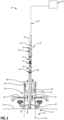
Figure 1 is a schematic illustration of an example of a subsea well system in which structural casing has been deployed into a seabed at a subsea well location, according to the invention; and -
Figure 2 is a partial cross-sectional illustration of an example of a deployment tool combined with a sensor system to facilitate deployment of the structural casing to a desired height above the mud line and within a desired offset angle with respect to the vertical, according to the invention. - In the following description, numerous details are set forth to provide an understanding of some embodiments of the present invention. However, it will be understood by those of ordinary skill in the art that numerous variations or modifications from the described embodiments may be possible, so long as these variations and modifications fall within the scope of the invention as defined by the claims.
- The present invention generally relates to a system and methodology for the combined use of a deployment tool and a sensor system to deploy a subsea structural casing. For example, the subsea structural casing may be deployed into a hole in the seabed once the hole is formed by, for example, jetting or drilling. The subsea structural casing is used in cooperation with a subsea well to enable desired well operations such asproduction of petroleum and/or other well fluids.
- The tool has an engagement region configured to couple with the subsea structural casing. By way of example, the engagement region may be in the form of a circumferential region which is inserted into the subsea structural casing to enable manipulation of the subsea structural casing. The tool and structural casing may be joined in a sealed engagement.
- The sensor system is operatively coupled with the tool and comprises a plurality of sensors. The sensor system is directly coupled with the tool and extends above the tool. The sensors are used to monitor height of the subsea structural casing above a mud line as well as angular deviation of the structural casing during deployment of the subsea structural casing into a seabed. This ensures, for example, the subsea structural casing extends a desired distance above the mud line and within a desired angular deviation limitwith respect vertical (e.g. within 1.25° of vertical) once the subsea structural casing is set in the seabed. In some embodiments, the sensor system may be used to monitor additional parameters.
- Referring generally to
Figure 1 , an example of asubsea well system 20 is illustrated. Thesubsea well system 20 may be used in a variety of subsea well applications and generally comprises astructural casing 22 which may be deployed at asuitable subsea location 24. Depending on the parameters of a given subsea operation, thestructural casing 22 comprises alow pressure housing 26 mounted over the top end of atubular casing 28. By way of example, the subsealow pressure housing 26 may be in the form of a subsea wellhead housing combined with thetubular casing 28 to form, in this example, a supporting/anchoring system 30. In some applications, the combinedhousing 26 andcasing 28 may be referred to as a conductor. - In the illustrated example, the
structural casing 22 extends into a seabed 32, e.g. into a subsea geologic formation, at thesubsea location 24. Thetubular casing 28 is inserted into the seabed 32 a desired distance so as to position the subsealow pressure housing 26 at a desired spacing above asea floor 34, e.g. above a mud line. Thestructural casing 22 may be used at a subsea well 36 having awellbore 38 extending down into the seabed/geologic formation 32. Various types of welltubulars 40, e.g. casing, production tubing, completion components, tubular equipment, may be suspended from, positioned in, positioned below, and/or otherwise located with respect to thestructural casing 22. - An
upper end 42 ofcasing 28 is inserted into an interior of subsealow pressure housing 26 and secured thereto in sealed engagement. Depending on the parameters associated with a given subsea operation, various types ofsubsea installation equipment 44 may be coupled withstructural casing 22, e.g. withlow pressure housing 26. By way of example,subsea equipment 44 may comprise portions ofa subsea wellhead as well as other equipment mounted to the subsea wellhead, e.g. a blowout preventer. In some applications, risers or other equipment may extend upwardly above thesubsea wellhead housing 24 toward asurface 46. Various types ofsurface facilities 48 such as surface vessels, platforms, or other surface facilities may be located atsurface 46 generally above well 36 to facilitate, for example, drilling operations, completion operations, production operations, or other well related operations. - To ensure proper coupling and operation of the
subsea installation equipment 44, thestructural casing 22 is positioned to extend a desired height above themud line 34 and at an orientation within a desired angle of deviation with respect to vertical. As illustrated inFigure 2 , atool 50 is used in cooperation with asensor system 52 to ensure positioning of thestructural casing 22 at the desired height above thesubseamud line 34 and within a desired range of angular deviation of thestructural casing 22 with respect to vertical. In some embodiments, thesensor system 52 comprises sensors for measuring weight of a structural string if thestructural casing 22 is sinking and/or depth of a drill bit if a hole is being drilled when thestructural casing 22 is set. - In an operational example, the
tool 50 is initially connected to thestructural casing 22. By way of example, thetool 50 initially may be connected tostructural casing 22 at thesurface facility 48 located atsurface 46. Thetool 50 is then used to deploy thestructural casing 22 to the desiredsubsea location 24. Additionally, thetool 50 may be used to move thestructural casing 22 into ahole 54 formed in theseabed 32.Hole 54 may be the upper end ofwellbore 38. - By way of example, the
hole 54 may be formed by jetting as thestructural casing 22 is lowered; or thestructural casing 22 may be dropped into ahole 54 formed via drilling. For example, thehole 54 is formed by directing a powerful jet into theseabed 32 and allowing the displaced seabed material to escape from the interior ofstructural casing 22 viajets 55 as illustrated. During deployment into and setting of thestructural casing 22 inhole 54, thesensor system 52 is used to monitor the height of thestructural casing 22 above thesubsea mud line 34 as well as the angular deviation of thestructural casing 22. - The
sensor system 52 may be operatively coupled with thetool 50 and may provide data to asurface control system 56 located on, for example, thesurface facility 48. Thesurface control system 56 may be a computer-based control system which processes data fromsensor system 52. The processed data is then used bysurface control system 56 to provide directions for controllingdeployment equipment 58. Thedeployment equipment 58 is used, in turn, for manipulating thetool 50. Depending on the parameters of a given operation and environment, thesensor system 52 andsurface control system 56 may communicate via a suitable wired orwireless telemetry system 59. - The
sensor system 52 is coupled directly and rigidly to thetool 50. Thesensor system 52 may be mounted on thetool 50 via amechanical coupling 60. Thesensor system 52 is coupled withtool 50 viacoupling 60 and extends above thetool 50 such that thesensor system 52 moves and tilts withtool 50. Thedeployment equipment 58 may comprise cable, coiled tubing, other types of tubing, or other suitable equipment controllable to manipulate the height and angular orientation of thestructural casing 22. - The
deployment equipment 58 is connected directly to thesensor system 52 via, for example, amechanical coupling 62. Depending on the structure oftool 50 andsensor system 52, thedeployment equipment 58 may additionally be connected directly to thetool 50 via, for example, themechanical coupling 62. - The
tool 50 comprises anengagement region 64 which may be inserted into the upper end ofstructural casing 22. For example,engagement region 64 may be inserted into the interior oflow pressure housing 26 until stopped by anabutment portion 66 ofengagement region 64. Alatch mechanism 68 or other suitable retention mechanism is used to securetool 50 to structural casing 22until thestructural casing 22 is set at the appropriate height and angular orientation. - If the
structural casing 22 has been placed in a drilled hole, thelatch mechanism 68 may then be released andtool 50 may be withdrawn fromstructural casing 22 to allow engagement ofstructural casing 22 with other subsea installation equipment,e.g. equipment 44. If, on the other hand, thestructural casing 22 has been placed via a jetting procedure, thetool 50 may then be manipulated in such a way so it can pass through thestructural casing 22 and allow a mud motor and drill bit to continue drillingthe next hole to a desired depth. In some embodiments, thesensor system 52 may be used to determine desirable depths, such as depth of the drill bit. Once a desired depth is drilled, thetool 50 may be retrieved back through thestructural casing 22. In some applications, thetool 50 may engage a running tool which remained in thestructural casing 22 during drilling, and then thetool 50 and drill bit can be retrieved together. It should be noted thelatch mechanism 68 may be selectively released via hydraulic input, mechanical input, or other suitable input based on the type of lighting mechanism. Depending on the parameters of a given operation, various subsequent wellbore formation processes, production processes, or other well related processes may be conducted upon release oftool 50. - Additionally,
sensor system 52 may comprise various different types of sensors to measure desired parameters associated with a given operation. For example, thesensor system 52 may comprise different types of sensors to monitor height above themud line 34 and also the angular deviation ofstructural casing 22 from vertical. By way of example,sensor system 52 may comprise various combinations of sensors which may include agyro 70, analtimeter 72, aninclinometer 74, aload cell 76, and apressure sensor 78. At least two of thesensors surface control system 56. -
Surface control system 56 processes the data and the resulting processed data allows thesurface control system 56 to provide inputs todeployment equipment 58 so as to adjust the height and angular inclination ofstructural casing 22. For example, data from thealtimeter 72 may be used to determine height of thelow pressure housing 26 abovemud line 34. Similarly, data fromgyro 70 andinclinometer 74 may be used to determine the angle of deviation ofstructural casing 22 relative to vertical. Data from theload cell 76 may be used to monitor weight, e.g. to monitor weight if thestructural casing 22 is sinking. - Based on this data, the
surface control system 56 is able to provide controlsignals to an operator and/or to the surface system controllingdeployment equipment 58 so as to adjust the height and/or angular inclination ofstructural casing 22. Other types of sensors and arrangements of sensors may be employed to provide the desired data on height and inclination as well as on other parameters. For example, data fromload cell 76 andpressure sensor 78 may be used in determining coupling and uncoupling oftool 50 as well as determining whether thestructural casing 22 continues to move intoseabed 32 during deployment. Various other sensors and combinations of sensors may be usedto monitor these parameters and/or additional parameters. - In an operational example, well construction for a subsea application begins by deploying and setting the
structural casing 22 at a planned height (e.g. 2-4 meters) above themud line 34 and within a predetermined deviation angle with respect tovertical (e.g. within 1.5° of vertical). Use of thesensor system 52 enables setting of thestructural casing 22 without using conventional mud mats, mud sticks, and ROVs for assisting in determining elevation. - By monitoring elevation and inclination angle of
tool 50 and structural casing 22 (viasensor system 52 mounted to tool 50), the entire setting operation can be performed with reduced ROV usage and without incurring the expense of conventional mud mats and mud sticks. Furthermore, thesensor system 52 enables monitoring of elevation and inclination even if the soil ofseabed 32 is disturbed during jetting ofhole 54. - Depending on the specifics of a given use, the shape and size, of
structural casing 22 may be adjusted. For example, thestructural casing 22 may have various diameters for use with various types of subsea wells. Similarly, thetool 50 may have various sizes and configurations for coupling with thestructural casing 22. In some embodiments, thetool 50 may comprise alongitudinal passage 80 through which jetting fluid may be delivered. Thetool 50 also may comprise a pressure chamber orchambers 82 for use in hydraulically setting and/or releasinglatch mechanism 68. However, these and other features may be changed or added to facilitate use oftool 50 with various types ofstructural casing 22 in different types of environments. Additionally, thesensor system 52 may comprise various types of sensors in addition to the illustratedsensors - Although a few embodiments of the invention have been described in detail above, those of ordinary skill in the art will readily appreciate that many modifications are possible so long as these modifications fall within the scope of this invention as defined in the claims.
Claims (12)
- A system (20) for use in a subsea well operation, comprising:a structural casing (22) having a subsea low pressure housing (26) and a tubular casing (28) with an upper end (42) inserted into the subsea low pressure housing (26) in sealing engagement;a tool (50) having an engagement region (64) inserted into an upper end of the structural casing (22) until the tool (50) is sufficiently coupled to the structural casing (22) to enable releasable latching of the tool (50) to the structural casing (22) and manipulation of the structural casing (22) when deployed and set at a subsea location(24); anda sensor system (52) mounted to the tool (50) to monitor height above a subsea mud line (34) and an angular deviation of the structural casing (22) from vertical during deployment of the structural casing (22) into a seabed (32), wherein the sensor system (52) is coupled rigidly and directly to the tool (50), wherein a lower end of the sensor system (52) is coupled with the tool via a mechanical coupling (60) such that the sensor system extends above the tool (50) and such that the sensor system (52) moves and tilts with the tool (50), wherein deployment equipment (58) comprising a cable, a coiled or other types tubing, or other suitable equipment controllable to manipulate the height and angular orientation of the structural casing is connected directly to the sensor system (52) .
- The system (20) as recited in claim 1, wherein the sensor system (52) comprises a plurality of different types of sensors (70, 72, 74, 76, 78).
- The system (20) as recited in claim 2, wherein the plurality of different types of sensors (70, 72, 74, 76, 78) comprises a gyro (70).
- The system (20) as recited in claim 2, wherein the plurality of different types of sensors (70, 72, 74, 76, 78) comprises an altimeter (72).
- The system (20) as recited in claim 2, wherein the plurality of different types of sensors (70, 72, 74, 76, 78) comprises an inclinometer (74).
- The system (20) as recited in claims 2, 3, 4 and 5, wherein the plurality of different types of sensors (70, 72, 74, 76, 78) comprises a load cell (76).
- The system (20) as recited in claims 2, 3, 4 and 5, wherein the plurality of different types of sensors (70, 72, 74, 76, 78) comprises a pressure sensor (78).
- The system (20) as recited in claim 2, wherein the plurality of different types of sensors (70, 72, 74, 76, 78) comprises a gyro (70), an altimeter (72), an inclinometer (74), a load cell (76), and a pressure sensor (78).
- A method, comprising:providing a structural casing (22) comprising a subsea wellhead low pressure housing (26) and a tubular casing (28) with an upper end (42) inserted into the subsea wellhead housing (24) in sealing engagement;connecting a tool (50) to the structural casing (22) by inserting an engagement region (64) of the tool (50) into an upper end of the structural casing (22);deploying the tool (50) and the structural casing (22) together to a subsea location(24);moving the structural casing (22) into a hole (54) in a seabed (32);using a sensor system (52) to monitor height of the structural casing (22) extending above a subsea mud line (34) and an angular deviation of the structural casing (22) from vertical as the structural casing (22) is moved into the hole (54), wherein the sensor system (52) is coupled rigidly and directly to the tool (50), wherein a lower end of the sensor system (52) is coupled with the tool via a mechanical coupling (60) such that the sensor system (52) extends above the tool (50) and such that the sensor system (52) moves and tilts with the tool (50) and wherein deployment equipment (58) comprising a cable, a coiled or other types tubing, or other suitable equipment controllable to manipulate the height and angular orientation of the structural casing (22), is connected directly to the sensor system (52) via a mechanical coupling (62) at an upper end of the sensor system (52); andadjusting the orientation of the structural casing (22) based on data provided by the sensor system (52) until the structural casing (22) is within 1.5° of vertical.
- The method as recited in claim 9, wherein moving comprises positioning the subsea wellhead low pressure housing (26) of the structural casing (22) at a desired height above the mud line (34).
- The method as recited in claim 9, wherein using comprises using at least two sensors of a plurality of sensors (70, 72, 74, 76, 78) which comprises a gyro (70), an altimeter (72), aninclinometer (74), a load cell (76), and a pressure sensor (78).
- The method as recited in claim 9, comprising releasing and withdrawing the tool (50) from the structural casing (22) and mounting subsea installation equipment (44) to the structural casing (22).
Applications Claiming Priority (1)
| Application Number | Priority Date | Filing Date | Title |
|---|---|---|---|
| US15/668,750 US10047598B1 (en) | 2017-08-04 | 2017-08-04 | Subsea monitor system |
Publications (2)
| Publication Number | Publication Date |
|---|---|
| EP3438350A1 EP3438350A1 (en) | 2019-02-06 |
| EP3438350B1 true EP3438350B1 (en) | 2024-02-21 |
Family
ID=63079361
Family Applications (1)
| Application Number | Title | Priority Date | Filing Date |
|---|---|---|---|
| EP18187216.9A Active EP3438350B1 (en) | 2017-08-04 | 2018-08-03 | Subsea deployment monitoring system |
Country Status (2)
| Country | Link |
|---|---|
| US (1) | US10047598B1 (en) |
| EP (1) | EP3438350B1 (en) |
Families Citing this family (3)
| Publication number | Priority date | Publication date | Assignee | Title |
|---|---|---|---|---|
| US12291931B2 (en) * | 2012-05-14 | 2025-05-06 | Innovex International, Inc. | Control/monitoring of initial construction of subsea wells |
| CN111894486B (en) * | 2020-04-30 | 2022-04-26 | 中国海洋石油集团有限公司 | Deepwater drilling surface conduit string feeding tool and use method thereof |
| GB2636260A (en) * | 2023-10-10 | 2025-06-11 | Innovex Int Inc | Control and/or monitoring of wells |
Family Cites Families (14)
| Publication number | Priority date | Publication date | Assignee | Title |
|---|---|---|---|---|
| US5069287A (en) * | 1990-08-01 | 1991-12-03 | Fmc Corporation | Retrievable guide base for subsea well |
| RU2066749C1 (en) * | 1996-03-14 | 1996-09-20 | Владимир Викторович Шеляго | Method for determination of wellbore inclination and direction of cased well |
| US6370784B1 (en) * | 1999-11-01 | 2002-04-16 | The Regents Of The University Of California | Tiltmeter leveling mechanism |
| US6386291B1 (en) * | 2000-10-12 | 2002-05-14 | David E. Short | Subsea wellhead system and method for drilling shallow water flow formations |
| US7770655B2 (en) * | 2005-07-20 | 2010-08-10 | Intermoor Inc. | Conductor casing installation by anchor handling/tug/supply vessel |
| NO335430B1 (en) * | 2010-04-14 | 2014-12-15 | Aker Subsea As | Underwater installation tools and procedures |
| GB201012176D0 (en) * | 2010-07-20 | 2010-09-01 | Metrol Tech Ltd | Well |
| US9091604B2 (en) * | 2011-03-03 | 2015-07-28 | Vetco Gray Inc. | Apparatus and method for measuring weight and torque at downhole locations while landing, setting, and testing subsea wellhead consumables |
| CA2865489A1 (en) * | 2012-03-13 | 2013-09-19 | Fmc Technologies, Inc. | Method and device for interfacing with subsea production equipment |
| US20140353036A1 (en) * | 2013-05-29 | 2014-12-04 | Vetco Gray Inc. | Apparatus and Method for Measuring Inclination in Subsea Running, Setting, and Testing Tools |
| WO2014194315A2 (en) * | 2013-05-31 | 2014-12-04 | Bp Corporation North America Inc. | Systems and methods for pulling subsea structures |
| KR101529654B1 (en) * | 2013-11-15 | 2015-06-19 | 한국지질자원연구원 | Coring system considering tilting of coring part and Method of compensating depth of coring part using the same |
| US20160305232A1 (en) * | 2015-04-20 | 2016-10-20 | Vetco Gray Inc. | System and method for monitoring tool orientation in a well |
| US9810044B2 (en) * | 2016-01-13 | 2017-11-07 | Chevron U.S.A. Inc. | Running a mudline closure device integral with a wellhead |
-
2017
- 2017-08-04 US US15/668,750 patent/US10047598B1/en active Active
-
2018
- 2018-08-03 EP EP18187216.9A patent/EP3438350B1/en active Active
Also Published As
| Publication number | Publication date |
|---|---|
| EP3438350A1 (en) | 2019-02-06 |
| US10047598B1 (en) | 2018-08-14 |
Similar Documents
| Publication | Publication Date | Title |
|---|---|---|
| US5662170A (en) | Method of drilling and completing wells | |
| EP2917462B1 (en) | Well isolation | |
| EP1050661B1 (en) | Improvements relating to subsea drilling of boreholes | |
| US5667023A (en) | Method and apparatus for drilling and completing wells | |
| US5842528A (en) | Method of drilling and completing wells | |
| GB2424432A (en) | Deep water drilling with casing | |
| WO2013167872A2 (en) | Drilling and lining subsea wellbores | |
| US9404358B2 (en) | Wiper plug for determining the orientation of a casing string in a wellbore | |
| NO20191012A1 (en) | An apparatus for forming at least a part of a production system for a wellbore, and a line for and a method of performing an operation to set a cement plug in a wellbore | |
| EP2884042A1 (en) | Downhole completion system and method | |
| AU2006314601B2 (en) | Wellbore system | |
| NO20191029A1 (en) | Measuring Strain In A Work String During Completion Operations | |
| US10605038B2 (en) | Latch assembly using on-board miniature hydraulics for RCD applications | |
| US10047598B1 (en) | Subsea monitor system | |
| AU2016425871B2 (en) | Reverse circulation debris removal tool for setting isolation seal assembly | |
| EP2964873B1 (en) | Wireline assisted coiled tubing portion and method for operation of such a coiled tubing portion | |
| EP3019694B1 (en) | Wiper plug for determining the orientation of a casing string in a wellbore | |
| US10400533B2 (en) | System and method for a downhole hanger assembly | |
| US9404347B1 (en) | Apparatus and method for connecting a riser from an offshore rig to a subsea structure | |
| CA3127440A1 (en) | System and methodology utilizing conductor sharing offset shoe | |
| Denney | Parque das Conchas (BC-10)-Delivering Deepwater Extended-Reach Wells in a Low-Fracture-Gradient Setting | |
| AU4058597A (en) | Method and apparatus for drilling and completing wells |
Legal Events
| Date | Code | Title | Description |
|---|---|---|---|
| PUAI | Public reference made under article 153(3) epc to a published international application that has entered the european phase |
Free format text: ORIGINAL CODE: 0009012 |
|
| STAA | Information on the status of an ep patent application or granted ep patent |
Free format text: STATUS: THE APPLICATION HAS BEEN PUBLISHED |
|
| AK | Designated contracting states |
Kind code of ref document: A1 Designated state(s): AL AT BE BG CH CY CZ DE DK EE ES FI FR GB GR HR HU IE IS IT LI LT LU LV MC MK MT NL NO PL PT RO RS SE SI SK SM TR |
|
| AX | Request for extension of the european patent |
Extension state: BA ME |
|
| STAA | Information on the status of an ep patent application or granted ep patent |
Free format text: STATUS: REQUEST FOR EXAMINATION WAS MADE |
|
| STAA | Information on the status of an ep patent application or granted ep patent |
Free format text: STATUS: EXAMINATION IS IN PROGRESS |
|
| 17P | Request for examination filed |
Effective date: 20190806 |
|
| RBV | Designated contracting states (corrected) |
Designated state(s): AL AT BE BG CH CY CZ DE DK EE ES FI FR GB GR HR HU IE IS IT LI LT LU LV MC MK MT NL NO PL PT RO RS SE SI SK SM TR |
|
| 17Q | First examination report despatched |
Effective date: 20190909 |
|
| GRAP | Despatch of communication of intention to grant a patent |
Free format text: ORIGINAL CODE: EPIDOSNIGR1 |
|
| STAA | Information on the status of an ep patent application or granted ep patent |
Free format text: STATUS: GRANT OF PATENT IS INTENDED |
|
| INTG | Intention to grant announced |
Effective date: 20230926 |
|
| GRAS | Grant fee paid |
Free format text: ORIGINAL CODE: EPIDOSNIGR3 |
|
| GRAA | (expected) grant |
Free format text: ORIGINAL CODE: 0009210 |
|
| STAA | Information on the status of an ep patent application or granted ep patent |
Free format text: STATUS: THE PATENT HAS BEEN GRANTED |
|
| AK | Designated contracting states |
Kind code of ref document: B1 Designated state(s): AL AT BE BG CH CY CZ DE DK EE ES FI FR GB GR HR HU IE IS IT LI LT LU LV MC MK MT NL NO PL PT RO RS SE SI SK SM TR |
|
| REG | Reference to a national code |
Ref country code: GB Ref legal event code: FG4D |
|
| REG | Reference to a national code |
Ref country code: CH Ref legal event code: EP |
|
| REG | Reference to a national code |
Ref country code: DE Ref legal event code: R096 Ref document number: 602018065451 Country of ref document: DE |
|
| REG | Reference to a national code |
Ref country code: IE Ref legal event code: FG4D |
|
| REG | Reference to a national code |
Ref country code: LT Ref legal event code: MG9D |
|
| REG | Reference to a national code |
Ref country code: NL Ref legal event code: MP Effective date: 20240221 |
|
| PG25 | Lapsed in a contracting state [announced via postgrant information from national office to epo] |
Ref country code: IS Free format text: LAPSE BECAUSE OF FAILURE TO SUBMIT A TRANSLATION OF THE DESCRIPTION OR TO PAY THE FEE WITHIN THE PRESCRIBED TIME-LIMIT Effective date: 20240621 |
|
| PG25 | Lapsed in a contracting state [announced via postgrant information from national office to epo] |
Ref country code: LT Free format text: LAPSE BECAUSE OF FAILURE TO SUBMIT A TRANSLATION OF THE DESCRIPTION OR TO PAY THE FEE WITHIN THE PRESCRIBED TIME-LIMIT Effective date: 20240221 |
|
| PG25 | Lapsed in a contracting state [announced via postgrant information from national office to epo] |
Ref country code: GR Free format text: LAPSE BECAUSE OF FAILURE TO SUBMIT A TRANSLATION OF THE DESCRIPTION OR TO PAY THE FEE WITHIN THE PRESCRIBED TIME-LIMIT Effective date: 20240522 |
|
| REG | Reference to a national code |
Ref country code: AT Ref legal event code: MK05 Ref document number: 1659227 Country of ref document: AT Kind code of ref document: T Effective date: 20240221 |
|
| PG25 | Lapsed in a contracting state [announced via postgrant information from national office to epo] |
Ref country code: HR Free format text: LAPSE BECAUSE OF FAILURE TO SUBMIT A TRANSLATION OF THE DESCRIPTION OR TO PAY THE FEE WITHIN THE PRESCRIBED TIME-LIMIT Effective date: 20240221 Ref country code: NL Free format text: LAPSE BECAUSE OF FAILURE TO SUBMIT A TRANSLATION OF THE DESCRIPTION OR TO PAY THE FEE WITHIN THE PRESCRIBED TIME-LIMIT Effective date: 20240221 Ref country code: RS Free format text: LAPSE BECAUSE OF FAILURE TO SUBMIT A TRANSLATION OF THE DESCRIPTION OR TO PAY THE FEE WITHIN THE PRESCRIBED TIME-LIMIT Effective date: 20240521 |
|
| PG25 | Lapsed in a contracting state [announced via postgrant information from national office to epo] |
Ref country code: ES Free format text: LAPSE BECAUSE OF FAILURE TO SUBMIT A TRANSLATION OF THE DESCRIPTION OR TO PAY THE FEE WITHIN THE PRESCRIBED TIME-LIMIT Effective date: 20240221 |
|
| PG25 | Lapsed in a contracting state [announced via postgrant information from national office to epo] |
Ref country code: AT Free format text: LAPSE BECAUSE OF FAILURE TO SUBMIT A TRANSLATION OF THE DESCRIPTION OR TO PAY THE FEE WITHIN THE PRESCRIBED TIME-LIMIT Effective date: 20240221 |
|
| PG25 | Lapsed in a contracting state [announced via postgrant information from national office to epo] |
Ref country code: RS Free format text: LAPSE BECAUSE OF FAILURE TO SUBMIT A TRANSLATION OF THE DESCRIPTION OR TO PAY THE FEE WITHIN THE PRESCRIBED TIME-LIMIT Effective date: 20240521 Ref country code: NL Free format text: LAPSE BECAUSE OF FAILURE TO SUBMIT A TRANSLATION OF THE DESCRIPTION OR TO PAY THE FEE WITHIN THE PRESCRIBED TIME-LIMIT Effective date: 20240221 Ref country code: LT Free format text: LAPSE BECAUSE OF FAILURE TO SUBMIT A TRANSLATION OF THE DESCRIPTION OR TO PAY THE FEE WITHIN THE PRESCRIBED TIME-LIMIT Effective date: 20240221 Ref country code: IS Free format text: LAPSE BECAUSE OF FAILURE TO SUBMIT A TRANSLATION OF THE DESCRIPTION OR TO PAY THE FEE WITHIN THE PRESCRIBED TIME-LIMIT Effective date: 20240621 Ref country code: HR Free format text: LAPSE BECAUSE OF FAILURE TO SUBMIT A TRANSLATION OF THE DESCRIPTION OR TO PAY THE FEE WITHIN THE PRESCRIBED TIME-LIMIT Effective date: 20240221 Ref country code: GR Free format text: LAPSE BECAUSE OF FAILURE TO SUBMIT A TRANSLATION OF THE DESCRIPTION OR TO PAY THE FEE WITHIN THE PRESCRIBED TIME-LIMIT Effective date: 20240522 Ref country code: FI Free format text: LAPSE BECAUSE OF FAILURE TO SUBMIT A TRANSLATION OF THE DESCRIPTION OR TO PAY THE FEE WITHIN THE PRESCRIBED TIME-LIMIT Effective date: 20240221 Ref country code: ES Free format text: LAPSE BECAUSE OF FAILURE TO SUBMIT A TRANSLATION OF THE DESCRIPTION OR TO PAY THE FEE WITHIN THE PRESCRIBED TIME-LIMIT Effective date: 20240221 Ref country code: BG Free format text: LAPSE BECAUSE OF FAILURE TO SUBMIT A TRANSLATION OF THE DESCRIPTION OR TO PAY THE FEE WITHIN THE PRESCRIBED TIME-LIMIT Effective date: 20240221 Ref country code: AT Free format text: LAPSE BECAUSE OF FAILURE TO SUBMIT A TRANSLATION OF THE DESCRIPTION OR TO PAY THE FEE WITHIN THE PRESCRIBED TIME-LIMIT Effective date: 20240221 |
|
| PG25 | Lapsed in a contracting state [announced via postgrant information from national office to epo] |
Ref country code: PL Free format text: LAPSE BECAUSE OF FAILURE TO SUBMIT A TRANSLATION OF THE DESCRIPTION OR TO PAY THE FEE WITHIN THE PRESCRIBED TIME-LIMIT Effective date: 20240221 Ref country code: PT Free format text: LAPSE BECAUSE OF FAILURE TO SUBMIT A TRANSLATION OF THE DESCRIPTION OR TO PAY THE FEE WITHIN THE PRESCRIBED TIME-LIMIT Effective date: 20240621 |
|
| PG25 | Lapsed in a contracting state [announced via postgrant information from national office to epo] |
Ref country code: SE Free format text: LAPSE BECAUSE OF FAILURE TO SUBMIT A TRANSLATION OF THE DESCRIPTION OR TO PAY THE FEE WITHIN THE PRESCRIBED TIME-LIMIT Effective date: 20240221 Ref country code: PT Free format text: LAPSE BECAUSE OF FAILURE TO SUBMIT A TRANSLATION OF THE DESCRIPTION OR TO PAY THE FEE WITHIN THE PRESCRIBED TIME-LIMIT Effective date: 20240621 Ref country code: PL Free format text: LAPSE BECAUSE OF FAILURE TO SUBMIT A TRANSLATION OF THE DESCRIPTION OR TO PAY THE FEE WITHIN THE PRESCRIBED TIME-LIMIT Effective date: 20240221 Ref country code: LV Free format text: LAPSE BECAUSE OF FAILURE TO SUBMIT A TRANSLATION OF THE DESCRIPTION OR TO PAY THE FEE WITHIN THE PRESCRIBED TIME-LIMIT Effective date: 20240221 |
|
| PG25 | Lapsed in a contracting state [announced via postgrant information from national office to epo] |
Ref country code: DK Free format text: LAPSE BECAUSE OF FAILURE TO SUBMIT A TRANSLATION OF THE DESCRIPTION OR TO PAY THE FEE WITHIN THE PRESCRIBED TIME-LIMIT Effective date: 20240221 |
|
| PG25 | Lapsed in a contracting state [announced via postgrant information from national office to epo] |
Ref country code: SM Free format text: LAPSE BECAUSE OF FAILURE TO SUBMIT A TRANSLATION OF THE DESCRIPTION OR TO PAY THE FEE WITHIN THE PRESCRIBED TIME-LIMIT Effective date: 20240221 |
|
| PG25 | Lapsed in a contracting state [announced via postgrant information from national office to epo] |
Ref country code: CZ Free format text: LAPSE BECAUSE OF FAILURE TO SUBMIT A TRANSLATION OF THE DESCRIPTION OR TO PAY THE FEE WITHIN THE PRESCRIBED TIME-LIMIT Effective date: 20240221 Ref country code: EE Free format text: LAPSE BECAUSE OF FAILURE TO SUBMIT A TRANSLATION OF THE DESCRIPTION OR TO PAY THE FEE WITHIN THE PRESCRIBED TIME-LIMIT Effective date: 20240221 |
|
| PG25 | Lapsed in a contracting state [announced via postgrant information from national office to epo] |
Ref country code: SK Free format text: LAPSE BECAUSE OF FAILURE TO SUBMIT A TRANSLATION OF THE DESCRIPTION OR TO PAY THE FEE WITHIN THE PRESCRIBED TIME-LIMIT Effective date: 20240221 |
|
| PG25 | Lapsed in a contracting state [announced via postgrant information from national office to epo] |
Ref country code: SM Free format text: LAPSE BECAUSE OF FAILURE TO SUBMIT A TRANSLATION OF THE DESCRIPTION OR TO PAY THE FEE WITHIN THE PRESCRIBED TIME-LIMIT Effective date: 20240221 Ref country code: SK Free format text: LAPSE BECAUSE OF FAILURE TO SUBMIT A TRANSLATION OF THE DESCRIPTION OR TO PAY THE FEE WITHIN THE PRESCRIBED TIME-LIMIT Effective date: 20240221 Ref country code: RO Free format text: LAPSE BECAUSE OF FAILURE TO SUBMIT A TRANSLATION OF THE DESCRIPTION OR TO PAY THE FEE WITHIN THE PRESCRIBED TIME-LIMIT Effective date: 20240221 Ref country code: EE Free format text: LAPSE BECAUSE OF FAILURE TO SUBMIT A TRANSLATION OF THE DESCRIPTION OR TO PAY THE FEE WITHIN THE PRESCRIBED TIME-LIMIT Effective date: 20240221 Ref country code: DK Free format text: LAPSE BECAUSE OF FAILURE TO SUBMIT A TRANSLATION OF THE DESCRIPTION OR TO PAY THE FEE WITHIN THE PRESCRIBED TIME-LIMIT Effective date: 20240221 Ref country code: CZ Free format text: LAPSE BECAUSE OF FAILURE TO SUBMIT A TRANSLATION OF THE DESCRIPTION OR TO PAY THE FEE WITHIN THE PRESCRIBED TIME-LIMIT Effective date: 20240221 |
|
| REG | Reference to a national code |
Ref country code: DE Ref legal event code: R097 Ref document number: 602018065451 Country of ref document: DE |
|
| PG25 | Lapsed in a contracting state [announced via postgrant information from national office to epo] |
Ref country code: IT Free format text: LAPSE BECAUSE OF FAILURE TO SUBMIT A TRANSLATION OF THE DESCRIPTION OR TO PAY THE FEE WITHIN THE PRESCRIBED TIME-LIMIT Effective date: 20240221 |
|
| PLBE | No opposition filed within time limit |
Free format text: ORIGINAL CODE: 0009261 |
|
| STAA | Information on the status of an ep patent application or granted ep patent |
Free format text: STATUS: NO OPPOSITION FILED WITHIN TIME LIMIT |
|
| PG25 | Lapsed in a contracting state [announced via postgrant information from national office to epo] |
Ref country code: IT Free format text: LAPSE BECAUSE OF FAILURE TO SUBMIT A TRANSLATION OF THE DESCRIPTION OR TO PAY THE FEE WITHIN THE PRESCRIBED TIME-LIMIT Effective date: 20240221 |
|
| 26N | No opposition filed |
Effective date: 20241122 |
|
| REG | Reference to a national code |
Ref country code: DE Ref legal event code: R119 Ref document number: 602018065451 Country of ref document: DE |
|
| REG | Reference to a national code |
Ref country code: CH Ref legal event code: PL |
|
| PG25 | Lapsed in a contracting state [announced via postgrant information from national office to epo] |
Ref country code: LU Free format text: LAPSE BECAUSE OF NON-PAYMENT OF DUE FEES Effective date: 20240803 |
|
| PG25 | Lapsed in a contracting state [announced via postgrant information from national office to epo] |
Ref country code: SI Free format text: LAPSE BECAUSE OF FAILURE TO SUBMIT A TRANSLATION OF THE DESCRIPTION OR TO PAY THE FEE WITHIN THE PRESCRIBED TIME-LIMIT Effective date: 20240221 Ref country code: CH Free format text: LAPSE BECAUSE OF NON-PAYMENT OF DUE FEES Effective date: 20240831 Ref country code: MC Free format text: LAPSE BECAUSE OF FAILURE TO SUBMIT A TRANSLATION OF THE DESCRIPTION OR TO PAY THE FEE WITHIN THE PRESCRIBED TIME-LIMIT Effective date: 20240221 |
|
| REG | Reference to a national code |
Ref country code: BE Ref legal event code: MM Effective date: 20240831 |
|
| PG25 | Lapsed in a contracting state [announced via postgrant information from national office to epo] |
Ref country code: DE Free format text: LAPSE BECAUSE OF NON-PAYMENT OF DUE FEES Effective date: 20250301 |
|
| PGFP | Annual fee paid to national office [announced via postgrant information from national office to epo] |
Ref country code: GB Payment date: 20250612 Year of fee payment: 8 |
|
| PG25 | Lapsed in a contracting state [announced via postgrant information from national office to epo] |
Ref country code: BE Free format text: LAPSE BECAUSE OF NON-PAYMENT OF DUE FEES Effective date: 20240831 |
|
| PG25 | Lapsed in a contracting state [announced via postgrant information from national office to epo] |
Ref country code: FR Free format text: LAPSE BECAUSE OF NON-PAYMENT OF DUE FEES Effective date: 20240831 |
|
| PG25 | Lapsed in a contracting state [announced via postgrant information from national office to epo] |
Ref country code: IE Free format text: LAPSE BECAUSE OF NON-PAYMENT OF DUE FEES Effective date: 20240803 |
|
| PGFP | Annual fee paid to national office [announced via postgrant information from national office to epo] |
Ref country code: NO Payment date: 20250808 Year of fee payment: 8 |
|
| PG25 | Lapsed in a contracting state [announced via postgrant information from national office to epo] |
Ref country code: CY Free format text: LAPSE BECAUSE OF FAILURE TO SUBMIT A TRANSLATION OF THE DESCRIPTION OR TO PAY THE FEE WITHIN THE PRESCRIBED TIME-LIMIT; INVALID AB INITIO Effective date: 20180803 |
|
| PG25 | Lapsed in a contracting state [announced via postgrant information from national office to epo] |
Ref country code: HU Free format text: LAPSE BECAUSE OF FAILURE TO SUBMIT A TRANSLATION OF THE DESCRIPTION OR TO PAY THE FEE WITHIN THE PRESCRIBED TIME-LIMIT; INVALID AB INITIO Effective date: 20180803 |