EP3438029A1 - Universal winding machine for a multitude of tray designs - Google Patents
Universal winding machine for a multitude of tray designs Download PDFInfo
- Publication number
- EP3438029A1 EP3438029A1 EP17001348.6A EP17001348A EP3438029A1 EP 3438029 A1 EP3438029 A1 EP 3438029A1 EP 17001348 A EP17001348 A EP 17001348A EP 3438029 A1 EP3438029 A1 EP 3438029A1
- Authority
- EP
- European Patent Office
- Prior art keywords
- suture
- winding
- tray
- package
- station
- Prior art date
- Legal status (The legal status is an assumption and is not a legal conclusion. Google has not performed a legal analysis and makes no representation as to the accuracy of the status listed.)
- Granted
Links
Images



Classifications
-
- A—HUMAN NECESSITIES
- A61—MEDICAL OR VETERINARY SCIENCE; HYGIENE
- A61B—DIAGNOSIS; SURGERY; IDENTIFICATION
- A61B17/00—Surgical instruments, devices or methods
- A61B17/04—Surgical instruments, devices or methods for suturing wounds; Holders or packages for needles or suture materials
- A61B17/06—Needles ; Sutures; Needle-suture combinations; Holders or packages for needles or suture materials
- A61B17/06114—Packages or dispensers for needles or sutures
-
- A—HUMAN NECESSITIES
- A61—MEDICAL OR VETERINARY SCIENCE; HYGIENE
- A61B—DIAGNOSIS; SURGERY; IDENTIFICATION
- A61B17/00—Surgical instruments, devices or methods
- A61B17/04—Surgical instruments, devices or methods for suturing wounds; Holders or packages for needles or suture materials
- A61B17/06—Needles ; Sutures; Needle-suture combinations; Holders or packages for needles or suture materials
- A61B17/06114—Packages or dispensers for needles or sutures
- A61B17/06133—Packages or dispensers for needles or sutures of parallelepipedal shape, e.g. made of rectangular or slightly oval panels
-
- B—PERFORMING OPERATIONS; TRANSPORTING
- B65—CONVEYING; PACKING; STORING; HANDLING THIN OR FILAMENTARY MATERIAL
- B65B—MACHINES, APPARATUS OR DEVICES FOR, OR METHODS OF, PACKAGING ARTICLES OR MATERIALS; UNPACKING
- B65B63/00—Auxiliary devices, not otherwise provided for, for operating on articles or materials to be packaged
- B65B63/04—Auxiliary devices, not otherwise provided for, for operating on articles or materials to be packaged for folding or winding articles, e.g. gloves or stockings
-
- B—PERFORMING OPERATIONS; TRANSPORTING
- B65—CONVEYING; PACKING; STORING; HANDLING THIN OR FILAMENTARY MATERIAL
- B65H—HANDLING THIN OR FILAMENTARY MATERIAL, e.g. SHEETS, WEBS, CABLES
- B65H54/00—Winding, coiling, or depositing filamentary material
- B65H54/02—Winding and traversing material on to reels, bobbins, tubes, or like package cores or formers
- B65H54/04—Winding and traversing material on to reels, bobbins, tubes, or like package cores or formers for making packages with closely-wound convolutions
-
- B—PERFORMING OPERATIONS; TRANSPORTING
- B65—CONVEYING; PACKING; STORING; HANDLING THIN OR FILAMENTARY MATERIAL
- B65H—HANDLING THIN OR FILAMENTARY MATERIAL, e.g. SHEETS, WEBS, CABLES
- B65H54/00—Winding, coiling, or depositing filamentary material
- B65H54/02—Winding and traversing material on to reels, bobbins, tubes, or like package cores or formers
- B65H54/22—Automatic winding machines, i.e. machines with servicing units for automatically performing end-finding, interconnecting of successive lengths of material, controlling and fault-detecting of the running material and replacing or removing of full or empty cores
-
- B—PERFORMING OPERATIONS; TRANSPORTING
- B65—CONVEYING; PACKING; STORING; HANDLING THIN OR FILAMENTARY MATERIAL
- B65H—HANDLING THIN OR FILAMENTARY MATERIAL, e.g. SHEETS, WEBS, CABLES
- B65H54/00—Winding, coiling, or depositing filamentary material
- B65H54/56—Winding of hanks or skeins
- B65H54/58—Swifts or reels adapted solely for the formation of hanks or skeins
-
- A—HUMAN NECESSITIES
- A61—MEDICAL OR VETERINARY SCIENCE; HYGIENE
- A61B—DIAGNOSIS; SURGERY; IDENTIFICATION
- A61B17/00—Surgical instruments, devices or methods
- A61B2017/00526—Methods of manufacturing
-
- A—HUMAN NECESSITIES
- A61—MEDICAL OR VETERINARY SCIENCE; HYGIENE
- A61B—DIAGNOSIS; SURGERY; IDENTIFICATION
- A61B17/00—Surgical instruments, devices or methods
- A61B17/04—Surgical instruments, devices or methods for suturing wounds; Holders or packages for needles or suture materials
- A61B17/06—Needles ; Sutures; Needle-suture combinations; Holders or packages for needles or suture materials
- A61B17/06114—Packages or dispensers for needles or sutures
- A61B2017/06142—Packages or dispensers for needles or sutures having needle- or suture- retaining members, e.g. holding tabs or needle parks
-
- B—PERFORMING OPERATIONS; TRANSPORTING
- B65—CONVEYING; PACKING; STORING; HANDLING THIN OR FILAMENTARY MATERIAL
- B65H—HANDLING THIN OR FILAMENTARY MATERIAL, e.g. SHEETS, WEBS, CABLES
- B65H2701/00—Handled material; Storage means
- B65H2701/30—Handled filamentary material
- B65H2701/39—Other types of filamentary materials or special applications
- B65H2701/3918—Surgical sutures
Definitions
- This invention relates to packages for surgical sutures and surgical needles, more particularly to equipment for winding surgical sutures and attached surgical needles into suture packages.
- Conventional surgical suture and needle packages serve several useful functions, including protecting the needles and sutures during handling, shipping, and storage.
- the packages facilitate access and release of the needles and sutures during surgery or other medical procedures prior to application.
- the packages may be used for surgical sutures armed with surgical needles or for unarmed surgical sutures without needles.
- Surgical needles and attached surgical sutures are well known in the art. Surgical needles and sutures are packaged in a variety of packages for delivery of the needles and sutures to the surgeon. The packages need to have a number of important characteristics, including ease of loading, ease of dispensing, and protection of the needle and the suture during handling, sterilization, shipping and storage.
- the common tray-type packages having a peripheral channel formed by a bottom channel with attached top portion with flaps or doors for receiving a suture are commonly used to package needles and suture combinations. These tray packages are typically made with moveable doors or members that cover the top of the track to prevent the suture from moving out of the track.
- These tray packages have a number of advantages. For example, the packages are relatively inexpensive to manufacture and are typically molded from biocompatible, inert polymeric materials.
- the track packages provide excellent protection to the sutures during processing, sterilization, shipment and storage. The packages are easy to handle by the surgical staff, and sutures are easy to withdraw from the tray packages in a consistent manner without tangles or lock-ups.
- One particular advantage of tray packages is their ease of suture loading in high speed, automated packaging process. Examples of tray packages are disclosed in US 6,135,272 , US 6,047,815 , US 6,644,469 , and US 8,011,499 .
- Surgical sutures are packaged in tray packages by using conventional winding fixtures.
- the fixture typically has a rotatable base with mounting pins.
- a tray package is mounted on the base and the pins such that the top of the tray package is facing upwardly.
- a winding stylus mounted to a winding head directs a length of suture down into a track of the suture tray. As the tray rotates the stylus rides or touches the bottom thereby opening the upper or lid flaps so that the suture is placed in the track in a uniform manner.
- Examples of such winding fixtures and styluses are disclosed in US 5,660,024 , US 5,664,404 , US 6,804,937 and US 6,463,719 .
- the current winding processes require a plastic tray with both a top piece and a bottom piece attached together.
- the top piece needs to have flaps or doors for receiving a suture. These flaps need to be opened to allow the suture to be guided in. This does not allow for other designs of packages such as a plastic tray consisting of a single piece bottom only or a side loaded package.
- the opening of the flaps influences the rpm (rounds per minute) that the package can be run at due to damage caused as the stylus impacts and pushes the flaps up.
- a stylus in a conventional winding fixture is rigidly mounted to the winding fixture and this does not allow for variations in the dimensions of tray packages. This may also result in potentially improper placement of the suture in the track of the package. This is caused because the stylus uses its back heel and its top along with the floor of the package to form the guidance of the suture.
- the suture changes speed as it is wound in an oval tray. It moves fast on the straight part of the tray while slowing down as it is going around the corners. Therefore, the suture can be anywhere from being on the floor of the tray during deceleration to being in contact with the top of the stylus during acceleration.
- the automated winding processes where the needle is automatically placed in the suture tray and then automatically wound are limited to single arm sutures of about 5/0 and above.
- the double armed sutures are typically hand placed in a plastic tray or a paper tray.
- the sutures in the smaller sizes are typically also hand placed in a foam retainer on a paper tray.
- the paper is required as a desiccant for the suture but there is not a current process to wind automatically.
- a novel adaptive suture and tray process starts with a multi station machine. It can be circular or inline and can contain as many stations as desired.
- the preferred embodiment is an eight station rotary type machine. The idea is to maintain the basic design while allowing for different tray designs such as
- the first station would be for the infeed of the desired tray using existing methods and devices.
- the second station is fundamentally open for custom modules required for packages such as pre-arming a needle retention area or adding a piece of foam for small needles. This station could also provide confirmation of tray present.
- the third station is for the loading of the needle. Additionally attached to station 3 can be a loading slide. This slide allows for the manual placing of the needle to be transported to the transfer to the tray. This is designed to accommodate double armed sutures down to 5/0. With a quick change of the slide grippers and robot grippers it will accommodate needle to 8/0 sutures (8 millimetre needles). The transfer of micro-needles with attached sutures into foam having been attached in a prior station can be robotically performed. This loading slide will also have locating points to attach an automated crimping station with direct loading of single armed suture sets.
- the suture winding assembly has a nest member for receiving a suture tray package having a winding channel.
- the assembly can provide a vacuum for assisting the winding of the sutures into a one piece bottom tray.
- the assembly also has a winding head for rotability and engaging the nest and tray package.
- the winding assembly has a suture control arm with a base member.
- the base member can have a top side, a bottom side and opposed front and rear lateral sides.
- the suture control arm can have a top side and a bottom side with a frontal opening mechanism fundamentally in a rounded shape.
- the suture control arm controls the entry point and the height of the suture. This facilitates the alignment of the suture wind therefore allowing for an easier removal of the suture.
- the suture control arm does not need to ride on the bottom of the tray floor in order to capture the suture. Therefore, the same suture control arm can be used, independent the height of the wall of the tray and independent of the kind of tray (top-loading or side-loading).
- the suture control arm is mounted to the base member.
- An outer ring that maintains the relative relationship of the suture control arm to the inside of the suture track of the package is formed to the rotatable winding head.
- the base member with the mounted suture control arm can be engaged in this outer ring. This could be realized by one or more running pulleys at the base member.
- the assembly also has a novel suture winding head with a multitude of suture guiding pins that either touch the floor of the tray or extend through it. These suture guiding pins have an angle to facilitate the control of the winds.
- Station 5 is for the lid placement. Either a paper lid or a plastic top can be placed by this station.
- station 4 is usually followed by station 5. Nevertheless, if the winding of the suture is done without vacuum, it can be advantageous to have station 5 followed by station 4.
- Station 6 is for the lid attachment.
- Station 7 is the offload station to an intermediate station. In this station, a camera inspection can be completed. There can be an offload to either an outfeed belt, a magazine or a rejection bin.
- Station 8 will be used for the verification of a successful unloading operation.
- Yet another aspect of the present invention is a method of winding a suture into a suture channel of a suture tray package using the suture control arm and the suture winding assembly specified above. This method can allow for speeds above 1000 rpm (rounds per minute). The state of the art is usually less than 400 rpm.
- the vacuum can be supplied in a constant manner from station 4 to station 6 as required by the package design.
- the winding process of the present invention can be used in a manual suture winding machine 10 according to Fig. 1 or in a semi-automatic suture winding machine 12 according to Fig. 2 .
- tray suture packages 14 of various designs can be used.
- the shape of the tray 14 can be essentially circular to oval. It can also be oval with finger indentations on the outer periphery (peanut shape).
- the manual suture winding machine 10 has a base platform 20 with a rotary dial 22 mounted thereon.
- Each of the package nests 24 is labelled so it will be possible to track the trays 14 during the winding process. There could be more than eight package nests 24 or less than this, depending on the number of stations necessary for the winding process.
- This type of rotary dial 22 is widely used in the art so it is not described in detail.
- the base plate 26 On the outside of the rotary dial 22 is the base plate 26 for mounting each of the stations.
- This modular design allows for quick customization of the stations as may be required by the design of the tray 14 or by station requirements.
- the package nest 24 is shown in greater detail in Fig. 3 .
- the package nest 24 has an inset 30 with an oval cavity 32.
- the cavity 32 is adapted for the specific tray 14 which is loaded into this cavity 32.
- the package nest 24 has two locating pins 34 and 36.
- the locating pins 34 and 36 reach through holes in the base member of the tray 14.
- the locating pins 34 and 36 can be mounted directly on the package nest 24 so they will be fixed in a specific position.
- the locating pins 34 and 36 can be mounted on the inset 30 so they can be adapted according to the specific design of the tray 14.
- the package nest 24 is capable of creating a vacuum through slots (not shown) that match the air slots 38 of the tray 14. Those slots can also be adapted according to the specific design of the tray 14. Therefore, only the inset 30 of the package nest 24 has to be changed in order to adapt the winding machine 10 for different designs of trays 14. There is no need for a further adjustment performed by an operator.
- the first station 40 is the tray infeed. This station 40 is shown at nine o'clock of the rotary dial 22 according to Fig. 1 . This type of infeed station 40 is widely used in the art so it is not described in detail. In principal, there are two options. There could be a single stack of trays 14 to be loaded into the package nests 24 or there could be a multi stack carrousel. In both cases the trays 14 are singularized and placed onto the package nests 24.
- the package nests 24 are rotated in an anticlockwise direction 42.
- the second station 44 is an open station for further options. For example, this station 44 could be used to load a top of the tray 14. It would also be possible to cut and place a foam in this station 44. If micro-needles do not fit into the needle park of the tray, such a foam might be necessary.
- a needle with an attached suture is fed in and parked in the tray 14.
- the needles are fed by an operator onto the loading shuttle 50.
- the loading shuttle 50 then moves in a linear motion to the pickup station 52.
- a motion slide like this is widely used in the art so it is not described in detail.
- the robot grippers 54 grip the needles from the loading shuttle 50.
- the shuttle 50 then returns to its loading position.
- the robot grippers 54 now travel to the package nest 24 of the rotary dial 22 and load the needle into the needle park of the tray 14.
- the loading shuttle 50 should provide a novel land area for gripping these micro-needles.
- the robot grippers 54 should be changed to tweezer-type grippers. At the package nest 24, the micro-needles are rotated into the added foam park of the tray 14 and then released.
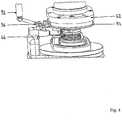
- the fourth station 60 is the novel winding station. This station 60 is shown in greater detail in Figs. 4 and 5 .
- the winding station 60 has a novel winding head 62.
- This winding head 62 provides the winding machine 10 with several different options that will enable the winding machine 10 to work with trays 14 of different designs and shapes.
- the winding head 62 has configurable suture guiding pins 64.
- the suture guiding pins 64 engage the floor of the tray 14 and keep it flat.
- the suture guiding pins 64 in conjunction with the suture control arm 66 and in conjunction with the winding speed work to place the suture in a specific pattern into the winding channel of the tray 14.
- the first wind of the suture should be placed at the bottom of the winding pin and the last wind of the suture should be placed at the top.
- a stripper plate 68 is actuated and pushes the suture off the suture guiding pins 64.
- the suture comes to lie on the bottom of the tray 14 in a controlled pattern.
- the suture guiding pins 64 have an angle 70 on their end that is configurable. This angle depends on the needs of the package 14 and its requirements for size and shape.
- the stripper plate 68 is able to hold a vacuum. This is necessary if the lid of the tray 14 can be placed before the winding of the suture. In this case, the stripper plate 68 will push the lid into its place at the same time it pushes the suture off the suture guiding pins 64. If the lid is placed after finishing the winding of the suture, the vacuum for the stripper plate 68 can be deactivated; it is also possible to do without the possibility of holding vacuum for the stripper plate 68.
- the suture control arm 66 is shown in more detail in Fig. 5 .
- the suture control arm 66 has a proximal end 80, a distal end 82, a top side 84 and a bottom side.
- the distal end 82 has a unique design that allows it to function with trays 14 that are top loaded and trays that are side loaded. This design also allows the suture control arm 66 to work with trays that have a top with pedals, a solid plastic top, a paper top or no top at all.
- the distal end 82 of the suture control arm 66 has a front standoff 86 and a rear standoff 88 incorporating a suture guiding channel 90.
- the suture guiding channel 90 keeps the suture located in reference to the bottom of the tray 14 without back pressure because this may cause damage of the suture.
- the top of the front standoff 86 of the distal end 82 has a predominantly rounded shape. This shape lessens the impact of a plastic tray to or of petals compared to an angled front and a flat top with a vertical drop at the back.
- the rear standoff 88 of the distal end 82 is basically a U shaped member with the opening of the U pointing towards the front standoff 86. This shape controls the entry point and the height of the suture. This facilitates the alignment of the suture wind therefore allowing for an easier removal of the suture.
- This specific shape of the distal end 82 of the suture control arm 66 allows for the minimal opening and the faster closing of the opened channel and allows for speeds above 1000 rpm. In contrast to that, most pedal trays with conventional stylus known in the art run at 400 rpm or even less.
- the suture control arm 66 is able to work with trays 14 known in the art both top loading trays and side loading trays. It works with trays with periphery shapes from round, oval, square and with side indentations (peanut shaped).
- the suture control arm 66 is mounted to a base member 92 (see Fig. 4 ).
- the winding head 62 of the winding station 60 has an outer ring 94.
- This outer ring 94 maintains the relative relationship between the winding station 60 and the base member 92.
- the base member 92 has a running pulley 96 piloted by the outer ring 94.
- the winding head 62 is rotated.
- the base member 92 is not rotated but it can adapt to the relative position of the winding head 62.
- This winding station 60 can wind trays with vacuum present or without vacuum present. If there is no vacuum present during the winding, it is usually necessary to have the lid placed directly after the needle parking and before starting the winding of the suture. Therefore, in this case the fifth station 50 should be placed after the third station 46 and before the fourth station 60.
- the fifth station 100 is a printing and lid placement station.
- the lids of the trays 14 are loaded from a stack onto a line 102.
- the lids could be pre-printed paper lids of plastic lids or the like. This type of station 100 is widely used in the art so it is not described in detail.
- the sixth station 104 is the lid attachment station.
- the lid could be attached by using ultrasonic sound or heated die, for example. By using ultrasonic sound or heated die it is possible to deform the standoff members of the trays, thereby locking the lid in place.
- This type of station 104 is widely used in the art so it is not described in detail.
- the seventh station 106 is an offloading station. After offloading, the trays 14 are usually transported to an intermediate inspection station (not shown). This type of station 106 is widely used in the art so it is not described in detail.
- the intermediate inspection station is usually the station where all camera inspections are performed.
- the tray 14 is then transferred to an outfeed section 108 which can be a belt or a magazine, for example. It could also be transferred to a reject area. This kind of intermediate inspection station is widely used in the art so it is not described in detail.
- the eighth station 110 is an open station for further options.
- this station 110 could be used for a camera check in order to confirm the offloading of the tray.
- the manual suture winding machine 10 is loaded and unloaded manually.
- the semi-automatic suture winding machine 12 as shown in Fig. 2 is loaded and unloaded automatically.
Landscapes
- Health & Medical Sciences (AREA)
- Surgery (AREA)
- Life Sciences & Earth Sciences (AREA)
- Engineering & Computer Science (AREA)
- Heart & Thoracic Surgery (AREA)
- Nuclear Medicine, Radiotherapy & Molecular Imaging (AREA)
- Dentistry (AREA)
- Biomedical Technology (AREA)
- Medical Informatics (AREA)
- Molecular Biology (AREA)
- Animal Behavior & Ethology (AREA)
- General Health & Medical Sciences (AREA)
- Public Health (AREA)
- Veterinary Medicine (AREA)
- Mechanical Engineering (AREA)
- Surgical Instruments (AREA)
Abstract
Description
- This invention relates to packages for surgical sutures and surgical needles, more particularly to equipment for winding surgical sutures and attached surgical needles into suture packages. Conventional surgical suture and needle packages serve several useful functions, including protecting the needles and sutures during handling, shipping, and storage. In addition, the packages facilitate access and release of the needles and sutures during surgery or other medical procedures prior to application. The packages may be used for surgical sutures armed with surgical needles or for unarmed surgical sutures without needles.
- Surgical needles and attached surgical sutures are well known in the art. Surgical needles and sutures are packaged in a variety of packages for delivery of the needles and sutures to the surgeon. The packages need to have a number of important characteristics, including ease of loading, ease of dispensing, and protection of the needle and the suture during handling, sterilization, shipping and storage.
- The common tray-type packages having a peripheral channel formed by a bottom channel with attached top portion with flaps or doors for receiving a suture are commonly used to package needles and suture combinations. These tray packages are typically made with moveable doors or members that cover the top of the track to prevent the suture from moving out of the track. These tray packages have a number of advantages. For example, the packages are relatively inexpensive to manufacture and are typically molded from biocompatible, inert polymeric materials. The track packages provide excellent protection to the sutures during processing, sterilization, shipment and storage. The packages are easy to handle by the surgical staff, and sutures are easy to withdraw from the tray packages in a consistent manner without tangles or lock-ups. One particular advantage of tray packages is their ease of suture loading in high speed, automated packaging process. Examples of tray packages are disclosed in
US 6,135,272 ,US 6,047,815 ,US 6,644,469 , andUS 8,011,499 . - Surgical sutures are packaged in tray packages by using conventional winding fixtures. The fixture typically has a rotatable base with mounting pins. A tray package is mounted on the base and the pins such that the top of the tray package is facing upwardly. Then a winding stylus mounted to a winding head directs a length of suture down into a track of the suture tray. As the tray rotates the stylus rides or touches the bottom thereby opening the upper or lid flaps so that the suture is placed in the track in a uniform manner. Examples of such winding fixtures and styluses are disclosed in
US 5,660,024 ,US 5,664,404 ,US 6,804,937 andUS 6,463,719 . - Although conventional winding processes with winding fixtures and styluses perform adequately for their intended use, there may be deficiencies associated with such winding processes.
- For example, the current winding processes require a plastic tray with both a top piece and a bottom piece attached together. The top piece needs to have flaps or doors for receiving a suture. These flaps need to be opened to allow the suture to be guided in. This does not allow for other designs of packages such as a plastic tray consisting of a single piece bottom only or a side loaded package. The opening of the flaps influences the rpm (rounds per minute) that the package can be run at due to damage caused as the stylus impacts and pushes the flaps up.
- Also for example, a stylus in a conventional winding fixture is rigidly mounted to the winding fixture and this does not allow for variations in the dimensions of tray packages. This may also result in potentially improper placement of the suture in the track of the package. This is caused because the stylus uses its back heel and its top along with the floor of the package to form the guidance of the suture. The suture changes speed as it is wound in an oval tray. It moves fast on the straight part of the tray while slowing down as it is going around the corners. Therefore, the suture can be anywhere from being on the floor of the tray during deceleration to being in contact with the top of the stylus during acceleration.
- Also the automated winding processes where the needle is automatically placed in the suture tray and then automatically wound are limited to single arm sutures of about 5/0 and above. The double armed sutures are typically hand placed in a plastic tray or a paper tray. The sutures in the smaller sizes are typically also hand placed in a foam retainer on a paper tray. There are new suture retainers that are being developed to reduce medical waste by going to a plastic bottom with a channel and a paper lid that also serves as a label. The paper is required as a desiccant for the suture but there is not a current process to wind automatically.
- There is a need in this art for a novel automated suture tray winding process that overcomes the deficiencies of the prior art and that will be easily and quickly adapted for all of the new and the old suture trays both top load or side load. Also there is a need to automatically load and wind micro needles and micro sutures and double armed sutures.
- Proceeding from this previously known prior art, it is an object of the present invention to provide a novel suture winding machine which can be easily adapted for different designs of tray packages and which is useful in a high-speed packaging process for packaging surgical sutures.
- Accordingly, a novel adaptive suture and tray process is disclosed. This process starts with a multi station machine. It can be circular or inline and can contain as many stations as desired. The preferred embodiment is an eight station rotary type machine. The idea is to maintain the basic design while allowing for different tray designs such as
- one piece bottom with paper top,
- one piece bottom with flat plastic top
- two piece bottom with a top with pedals or doors and paper lid,
- a tray without an outside lip or
- a tray with sideloading of suture.
- The first station would be for the infeed of the desired tray using existing methods and devices.
- The second station is fundamentally open for custom modules required for packages such as pre-arming a needle retention area or adding a piece of foam for small needles. This station could also provide confirmation of tray present.
- The third station is for the loading of the needle. Additionally attached to station 3 can be a loading slide. This slide allows for the manual placing of the needle to be transported to the transfer to the tray. This is designed to accommodate double armed sutures down to 5/0. With a quick change of the slide grippers and robot grippers it will accommodate needle to 8/0 sutures (8 millimetre needles). The transfer of micro-needles with attached sutures into foam having been attached in a prior station can be robotically performed. This loading slide will also have locating points to attach an automated crimping station with direct loading of single armed suture sets.
- Station 4 of the present invention is a suture winding assembly. The suture winding assembly has a nest member for receiving a suture tray package having a winding channel. The assembly can provide a vacuum for assisting the winding of the sutures into a one piece bottom tray. The assembly also has a winding head for rotability and engaging the nest and tray package. Furthermore, the winding assembly has a suture control arm with a base member. The base member can have a top side, a bottom side and opposed front and rear lateral sides. The suture control arm can have a top side and a bottom side with a frontal opening mechanism fundamentally in a rounded shape. Furthermore, there is a U shaped member at the rear of the suture control arm that controls the entry point and the height of the suture. This facilitates the alignment of the suture wind therefore allowing for an easier removal of the suture. The suture control arm does not need to ride on the bottom of the tray floor in order to capture the suture. Therefore, the same suture control arm can be used, independent the height of the wall of the tray and independent of the kind of tray (top-loading or side-loading).
- The suture control arm is mounted to the base member. An outer ring that maintains the relative relationship of the suture control arm to the inside of the suture track of the package is formed to the rotatable winding head. The base member with the mounted suture control arm can be engaged in this outer ring. This could be realized by one or more running pulleys at the base member.
- The assembly also has a novel suture winding head with a multitude of suture guiding pins that either touch the floor of the tray or extend through it. These suture guiding pins have an angle to facilitate the control of the winds. There is a stripper plate that pushes down after winding and before the winding head disengages the winding nest. This stripping motion causes the sutures to lay in a controlled manner.
- Station 5 is for the lid placement. Either a paper lid or a plastic top can be placed by this station. When the winding of the suture is performed under vacuum, station 4 is usually followed by station 5. Nevertheless, if the winding of the suture is done without vacuum, it can be advantageous to have station 5 followed by station 4.
- Station 6 is for the lid attachment. For example, there could be either staking or ultrasonic attachment.
- Station 7 is the offload station to an intermediate station. In this station, a camera inspection can be completed. There can be an offload to either an outfeed belt, a magazine or a rejection bin.
- Station 8 will be used for the verification of a successful unloading operation.
- Yet another aspect of the present invention is a method of winding a suture into a suture channel of a suture tray package using the suture control arm and the suture winding assembly specified above. This method can allow for speeds above 1000 rpm (rounds per minute). The state of the art is usually less than 400 rpm.
- The vacuum can be supplied in a constant manner from station 4 to station 6 as required by the package design.
- These and other features and advantages of the present invention will become more apparent from the following description and accompanying drawings.
- Further advantages and features of the invention can be gathered from the features which are further specified in the claims and from the following exemplary embodiments.
- In the following text, the invention will be described and explained in greater detail using the exemplary embodiments which are shown in the drawings.
- Fig. 1
- is a schematic view of a first embodiment of the machine showing a manual winder.
- Fig. 2
- is a schematic view of a second embodiment of the machine showing a semi-automatic winder.
- Fig. 3
- is a schematic view of one of the winding nests of the machine according to
Figs. 1 or2 with a tray placed into it. - Fig. 4
- is a schematic view of the winding station according to
Figs 1 or2 with winding head, suture control arm and base member. - Fig. 5
- is a schematic view of the winding head of the winding station according to
Fig. 4 . - Fig. 6
- is a schematic view of the suture control arm of the winding station according to
Fig. 4 . - The winding process of the present invention can be used in a manual
suture winding machine 10 according toFig. 1 or in a semi-automaticsuture winding machine 12 according toFig. 2 . In both cases, tray suture packages 14 of various designs can be used. The shape of thetray 14 can be essentially circular to oval. It can also be oval with finger indentations on the outer periphery (peanut shape). - Referring to
Fig. 1 , the manualsuture winding machine 10 has abase platform 20 with arotary dial 22 mounted thereon. In this preferred embodiment there are eightpackage nests 24 on therotary dial 22. Each of thepackage nests 24 is labelled so it will be possible to track thetrays 14 during the winding process. There could be more than eightpackage nests 24 or less than this, depending on the number of stations necessary for the winding process. - This type of
rotary dial 22 is widely used in the art so it is not described in detail. On the outside of therotary dial 22 is thebase plate 26 for mounting each of the stations. This modular design allows for quick customization of the stations as may be required by the design of thetray 14 or by station requirements. - The
package nest 24 is shown in greater detail inFig. 3 . Thepackage nest 24 has aninset 30 with anoval cavity 32. Thecavity 32 is adapted for thespecific tray 14 which is loaded into thiscavity 32. In order to load adifferent tray 14, only theinset 30 has to be changed in order to accommodate atray 14 with a different shape or a different diameter. Thepackage nest 24 has two locatingpins tray 14. The locating pins 34 and 36 can be mounted directly on thepackage nest 24 so they will be fixed in a specific position. In contrast to that, the locating pins 34 and 36 can be mounted on theinset 30 so they can be adapted according to the specific design of thetray 14. Thepackage nest 24 is capable of creating a vacuum through slots (not shown) that match theair slots 38 of thetray 14. Those slots can also be adapted according to the specific design of thetray 14. Therefore, only theinset 30 of thepackage nest 24 has to be changed in order to adapt the windingmachine 10 for different designs oftrays 14. There is no need for a further adjustment performed by an operator. - The
first station 40 is the tray infeed. Thisstation 40 is shown at nine o'clock of therotary dial 22 according toFig. 1 . This type ofinfeed station 40 is widely used in the art so it is not described in detail. In principal, there are two options. There could be a single stack oftrays 14 to be loaded into thepackage nests 24 or there could be a multi stack carrousel. In both cases thetrays 14 are singularized and placed onto thepackage nests 24. - In the shown embodiment, the
package nests 24 are rotated in ananticlockwise direction 42. Thesecond station 44 is an open station for further options. For example, thisstation 44 could be used to load a top of thetray 14. It would also be possible to cut and place a foam in thisstation 44. If micro-needles do not fit into the needle park of the tray, such a foam might be necessary. - In the third station 46 a needle with an attached suture is fed in and parked in the
tray 14. The needles are fed by an operator onto the loadingshuttle 50. The loadingshuttle 50 then moves in a linear motion to thepickup station 52. A motion slide like this is widely used in the art so it is not described in detail. At thepickup station 52 therobot grippers 54 grip the needles from the loadingshuttle 50. Theshuttle 50 then returns to its loading position. The robot grippers 54 now travel to thepackage nest 24 of therotary dial 22 and load the needle into the needle park of thetray 14. - Depending on the kind and the size of the needle to be loaded into the needle park, it might be necessary to change the tools of the loading
shuttle 50 and of therobot grippers 54. For micro-needles, the loadingshuttle 50 should provide a novel land area for gripping these micro-needles. Furthermore, therobot grippers 54 should be changed to tweezer-type grippers. At thepackage nest 24, the micro-needles are rotated into the added foam park of thetray 14 and then released. - The
fourth station 60 is the novel winding station. Thisstation 60 is shown in greater detail inFigs. 4 and5 . The windingstation 60 has anovel winding head 62. This windinghead 62 provides the windingmachine 10 with several different options that will enable the windingmachine 10 to work withtrays 14 of different designs and shapes. The windinghead 62 has configurable suture guiding pins 64. The suture guiding pins 64 engage the floor of thetray 14 and keep it flat. Furthermore, the suture guiding pins 64 in conjunction with thesuture control arm 66 and in conjunction with the winding speed work to place the suture in a specific pattern into the winding channel of thetray 14. In order to facilitate the withdrawing of the suture, the first wind of the suture should be placed at the bottom of the winding pin and the last wind of the suture should be placed at the top. After finishing the winding astripper plate 68 is actuated and pushes the suture off the suture guiding pins 64. The suture comes to lie on the bottom of thetray 14 in a controlled pattern. - The suture guiding pins 64 have an
angle 70 on their end that is configurable. This angle depends on the needs of thepackage 14 and its requirements for size and shape. - The
stripper plate 68 is able to hold a vacuum. This is necessary if the lid of thetray 14 can be placed before the winding of the suture. In this case, thestripper plate 68 will push the lid into its place at the same time it pushes the suture off the suture guiding pins 64. If the lid is placed after finishing the winding of the suture, the vacuum for thestripper plate 68 can be deactivated; it is also possible to do without the possibility of holding vacuum for thestripper plate 68. - The
suture control arm 66 is shown in more detail inFig. 5 . Thesuture control arm 66 has aproximal end 80, a distal end 82, atop side 84 and a bottom side. The distal end 82 has a unique design that allows it to function withtrays 14 that are top loaded and trays that are side loaded. This design also allows thesuture control arm 66 to work with trays that have a top with pedals, a solid plastic top, a paper top or no top at all. The distal end 82 of thesuture control arm 66 has afront standoff 86 and arear standoff 88 incorporating asuture guiding channel 90. Thesuture guiding channel 90 keeps the suture located in reference to the bottom of thetray 14 without back pressure because this may cause damage of the suture. The top of thefront standoff 86 of the distal end 82 has a predominantly rounded shape. This shape lessens the impact of a plastic tray to or of petals compared to an angled front and a flat top with a vertical drop at the back. Therear standoff 88 of the distal end 82 is basically a U shaped member with the opening of the U pointing towards thefront standoff 86. This shape controls the entry point and the height of the suture. This facilitates the alignment of the suture wind therefore allowing for an easier removal of the suture. - This specific shape of the distal end 82 of the
suture control arm 66 allows for the minimal opening and the faster closing of the opened channel and allows for speeds above 1000 rpm. In contrast to that, most pedal trays with conventional stylus known in the art run at 400 rpm or even less. - The
suture control arm 66 is able to work withtrays 14 known in the art both top loading trays and side loading trays. It works with trays with periphery shapes from round, oval, square and with side indentations (peanut shaped). - The
suture control arm 66 is mounted to a base member 92 (seeFig. 4 ). The windinghead 62 of the windingstation 60 has anouter ring 94. Thisouter ring 94 maintains the relative relationship between the windingstation 60 and thebase member 92. For this purpose thebase member 92 has a runningpulley 96 piloted by theouter ring 94. During the winding process, the windinghead 62 is rotated. Thebase member 92 is not rotated but it can adapt to the relative position of the windinghead 62. - This winding
station 60 can wind trays with vacuum present or without vacuum present. If there is no vacuum present during the winding, it is usually necessary to have the lid placed directly after the needle parking and before starting the winding of the suture. Therefore, in this case thefifth station 50 should be placed after thethird station 46 and before thefourth station 60. - The
fifth station 100 is a printing and lid placement station. In this station, the lids of thetrays 14 are loaded from a stack onto aline 102. In contrast to that, there could also be fan-fold lid, which are separated at the end of theline 102. The lids could be pre-printed paper lids of plastic lids or the like. This type ofstation 100 is widely used in the art so it is not described in detail. - The
sixth station 104 is the lid attachment station. The lid could be attached by using ultrasonic sound or heated die, for example. By using ultrasonic sound or heated die it is possible to deform the standoff members of the trays, thereby locking the lid in place. This type ofstation 104 is widely used in the art so it is not described in detail. - The
seventh station 106 is an offloading station. After offloading, thetrays 14 are usually transported to an intermediate inspection station (not shown). This type ofstation 106 is widely used in the art so it is not described in detail. The intermediate inspection station is usually the station where all camera inspections are performed. Thetray 14 is then transferred to anoutfeed section 108 which can be a belt or a magazine, for example. It could also be transferred to a reject area. This kind of intermediate inspection station is widely used in the art so it is not described in detail. - The
eighth station 110 is an open station for further options. For example, thisstation 110 could be used for a camera check in order to confirm the offloading of the tray. - The manual
suture winding machine 10 is loaded and unloaded manually. In contrast to that, the semi-automaticsuture winding machine 12 as shown inFig. 2 is loaded and unloaded automatically. - In contrast to the circular layout of the
rotary dial 22, there could also be an inline form for thesuture winding machine rotary dial 22 and an inline form.
Claims (14)
- A machine (10, 12) for winding suture into a suture tray package (14) comprising:- a base platform (20)- a plurality of package nests (24), each package nest (24) comprising at least two locating pins (34, 36) extending up from the package nests (24),- a first workstation (40) for placing an empty tray (14) onto one of the package nests (24),- a further workstation (46) for feeding a needle with an attached suture in the tray and parking said needle in the tray,- a winding station (60) for winding the suture into a winding channel of the tray, said winding station (60) comprising- - a rotatable winding head (62) with a plurality of configurable suture guiding pins (64), the guiding pins (64) being configured as to engage the floor of the tray (14) and to keep it flat,- - a stripper plate (68) for pushing the wound suture off the suture guiding pins (64),- - a suture control arm (66), said suture control arm (66) having a proximal end (80), a distal end (82), a top side (84) and a bottom side, said distal end (82) of the suture control arm (66) having a front standoff (86) and a rear standoff (88) incorporating a suture guiding channel (90),- - a base member (92) for mounting the suture control (66) arm to the base platform (20),- a lid placement station (100) for placing a lids onto one of the package nests (24),- a lid attachment station (104) for attaching the lid to the tray (14),- an offloading station (106) for removing said trays (14) from the package nests (24).
- Winding machine according to Claim 1,
wherein- each package nest (24) comprises a plurality of slots in order to create a vacuum. - Winding machine according to Claim 1 or 2,
wherein- each package nest (24) comprises an inset (30) with a cavity (32) adapted for the tray. - Winding machine according to Claim 3,
wherein- the locating pins (34, 36) are mounted to the inset (30). - Winding machine according to Claim 3 or 4,
wherein- the inset (30) comprises a plurality of air slots (38) in order to create a vacuum. - Winding machine according to one of the preceding claims, wherein- the suture guiding pins (64) have a configurable angle (70) in their end.
- Winding machine according to one of the preceding claims, wherein- the stripper plate (68) is able to hold a vacuum.
- Winding machine according to one of the preceding claims, wherein- the top of the front standoff member (86) of the distal end (82) of the suture control arm (66) has a predominantly rounded shape.
- Winding machine according to one of the preceding claims, wherein- the rear standoff (88) of the distal end (82) of the suture control arm (66) is basically a U shaped member with to opening of the U pointing towards the front standoff (86).
- Winding machine according to one of the preceding claims, wherein- the winding head (62) of the winding station (60) has an outer ring (94),- the base member (92) of the winding station (60) has at least one running pulley (94) piloted by the outer ring (94).
- Winding machine according to one of the preceding claims, further comprising- a rotary dial (22) rotatably mounted to the base platform 820)- a plurality of package nests (24), each package nest (24) rotatably mounted to the rotary dial (22), each package nest (24) comprising at least two locating pins (34, 36) extending up from the package nests (24).
- Winding machine according to Claim 11,
wherein- there is a base plate (26) outside of the rotary dial (22) mounted to the base platform (20),- the workstations (40, 44, 46, 60, 100, 104, 106, 110) are mounted to the base plate (26). - Winding machine according to one of the preceding claims, wherein- there are eight package nests (24) mounted to the rotary dial (22).
- Winding machine according to one of the preceding claims, wherein- there is second workstation (44) between the first workstation (40) and the next workstation (46).
Priority Applications (5)
| Application Number | Priority Date | Filing Date | Title |
|---|---|---|---|
| EP17001348.6A EP3438029B1 (en) | 2017-08-01 | 2017-08-01 | Universal winding machine for a multitude of tray designs |
| ES17001348T ES2770352T3 (en) | 2017-08-01 | 2017-08-01 | Universal winder machine for a multitude of tray designs |
| CA3010818A CA3010818C (en) | 2017-08-01 | 2018-07-09 | Universal winding machine for a multitude of tray designs |
| US16/047,454 US10981686B2 (en) | 2017-08-01 | 2018-07-27 | Universal winding machine for a multitude of tray designs |
| CN201810859501.3A CN109316216B (en) | 2017-08-01 | 2018-07-31 | Universal winding machine for multiple tray designs |
Applications Claiming Priority (1)
| Application Number | Priority Date | Filing Date | Title |
|---|---|---|---|
| EP17001348.6A EP3438029B1 (en) | 2017-08-01 | 2017-08-01 | Universal winding machine for a multitude of tray designs |
Publications (2)
| Publication Number | Publication Date |
|---|---|
| EP3438029A1 true EP3438029A1 (en) | 2019-02-06 |
| EP3438029B1 EP3438029B1 (en) | 2019-11-20 |
Family
ID=59569102
Family Applications (1)
| Application Number | Title | Priority Date | Filing Date |
|---|---|---|---|
| EP17001348.6A Active EP3438029B1 (en) | 2017-08-01 | 2017-08-01 | Universal winding machine for a multitude of tray designs |
Country Status (5)
| Country | Link |
|---|---|
| US (1) | US10981686B2 (en) |
| EP (1) | EP3438029B1 (en) |
| CN (1) | CN109316216B (en) |
| CA (1) | CA3010818C (en) |
| ES (1) | ES2770352T3 (en) |
Cited By (1)
| Publication number | Priority date | Publication date | Assignee | Title |
|---|---|---|---|---|
| EP3909518A1 (en) | 2020-05-14 | 2021-11-17 | B. Braun Surgical, S.A. | Needle holder and package for surgical suture material |
Families Citing this family (6)
| Publication number | Priority date | Publication date | Assignee | Title |
|---|---|---|---|---|
| EP3620396B1 (en) * | 2018-09-10 | 2021-05-19 | Harro Höfliger Verpackungsmaschinen GmbH | Universal winding machine for a multitude of tray designs |
| EP3725718B1 (en) * | 2019-04-18 | 2021-09-08 | Harro Höfliger Verpackungsmaschinen GmbH | Winding head for surgical sutures |
| ES2932482B2 (en) * | 2021-07-09 | 2023-05-19 | Gp Tecnic Sl | WINDING MACHINE FOR RAFFIA REELS |
| EP4666961A4 (en) | 2023-02-17 | 2026-05-27 | Mani Inc | Device for winding reinforced sutures, tray for receiving reinforced sutures and tray for receiving medical instruments |
| CN117022739B (en) * | 2023-06-27 | 2025-08-01 | 哈工大机器人(中山)无人装备与人工智能研究院 | Box-packed putting is gone into in winding plastic |
| CN121084728B (en) * | 2025-10-24 | 2026-06-23 | 长恩精机(长兴)有限公司 | Full-automatic wire winding encapsulation equipment of medical suture line |
Citations (11)
| Publication number | Priority date | Publication date | Assignee | Title |
|---|---|---|---|---|
| JPS60209470A (en) * | 1984-04-03 | 1985-10-22 | Teijin Ltd | Peeling device of outermost layer thread of thread package |
| EP0760228A1 (en) * | 1995-08-31 | 1997-03-05 | Ethicon, Inc. | Zipper package winding tool mechanism |
| US5664404A (en) | 1995-08-31 | 1997-09-09 | Ethicon, Inc. | Automatic zipper package winding and packaging machine |
| US6047815A (en) | 1998-08-31 | 2000-04-11 | Ethicon, Inc. | Package for sutures |
| US6135272A (en) | 1999-10-22 | 2000-10-24 | Ethicon, Inc. | Package for sutures |
| US6463719B2 (en) | 2000-12-13 | 2002-10-15 | Ethicon | Suture winding machine, suture tray package, and method of winding sutures |
| US6644469B2 (en) | 2001-07-11 | 2003-11-11 | Ethicon, Inc. | Large needle oval wound plastic suture package |
| US20040177594A1 (en) * | 2003-03-13 | 2004-09-16 | Dey Clifford A. | Package winding machine |
| US20080017526A1 (en) * | 2005-03-11 | 2008-01-24 | Michael Prescott | Suture winding device and methods of use thereof |
| US8011499B2 (en) | 2008-12-16 | 2011-09-06 | Ethicon, Inc. | Suture tray package |
| WO2016175935A1 (en) * | 2015-04-29 | 2016-11-03 | Ethicon, Inc. | Stylus winding fixture for winding surgical sutures |
Family Cites Families (6)
| Publication number | Priority date | Publication date | Assignee | Title |
|---|---|---|---|---|
| US5052551A (en) | 1991-01-31 | 1991-10-01 | Ethicon, Inc. | Oval wrap suture package with unequal end radii |
| US5271495A (en) * | 1992-04-01 | 1993-12-21 | Ethicon, Inc. | Oval wrap suture package with rotary wheel |
| US5487216A (en) | 1994-01-13 | 1996-01-30 | Ethicon, Inc. | Control system for an automatic needle-suture assembly and packaging machine |
| US5661954A (en) * | 1995-08-31 | 1997-09-02 | Ethicon, Inc. | Needle feed wheel and needle transfer mechanism |
| US5695138A (en) * | 1996-09-03 | 1997-12-09 | Ethicon, Inc. | Winding fixture for surgical suture package |
| US7837455B2 (en) | 2006-07-28 | 2010-11-23 | Ethicon, Inc. | Apparatus and method for making suture packages |
-
2017
- 2017-08-01 ES ES17001348T patent/ES2770352T3/en active Active
- 2017-08-01 EP EP17001348.6A patent/EP3438029B1/en active Active
-
2018
- 2018-07-09 CA CA3010818A patent/CA3010818C/en active Active
- 2018-07-27 US US16/047,454 patent/US10981686B2/en active Active
- 2018-07-31 CN CN201810859501.3A patent/CN109316216B/en active Active
Patent Citations (13)
| Publication number | Priority date | Publication date | Assignee | Title |
|---|---|---|---|---|
| JPS60209470A (en) * | 1984-04-03 | 1985-10-22 | Teijin Ltd | Peeling device of outermost layer thread of thread package |
| EP0760228A1 (en) * | 1995-08-31 | 1997-03-05 | Ethicon, Inc. | Zipper package winding tool mechanism |
| US5660024A (en) | 1995-08-31 | 1997-08-26 | Ethicon, Inc. | Zipper package winding tool mechanism |
| US5664404A (en) | 1995-08-31 | 1997-09-09 | Ethicon, Inc. | Automatic zipper package winding and packaging machine |
| US6047815A (en) | 1998-08-31 | 2000-04-11 | Ethicon, Inc. | Package for sutures |
| US6135272A (en) | 1999-10-22 | 2000-10-24 | Ethicon, Inc. | Package for sutures |
| US6463719B2 (en) | 2000-12-13 | 2002-10-15 | Ethicon | Suture winding machine, suture tray package, and method of winding sutures |
| US6644469B2 (en) | 2001-07-11 | 2003-11-11 | Ethicon, Inc. | Large needle oval wound plastic suture package |
| US20040177594A1 (en) * | 2003-03-13 | 2004-09-16 | Dey Clifford A. | Package winding machine |
| US6804937B2 (en) | 2003-03-13 | 2004-10-19 | Ethicon, Inc. | Package winding machine |
| US20080017526A1 (en) * | 2005-03-11 | 2008-01-24 | Michael Prescott | Suture winding device and methods of use thereof |
| US8011499B2 (en) | 2008-12-16 | 2011-09-06 | Ethicon, Inc. | Suture tray package |
| WO2016175935A1 (en) * | 2015-04-29 | 2016-11-03 | Ethicon, Inc. | Stylus winding fixture for winding surgical sutures |
Cited By (2)
| Publication number | Priority date | Publication date | Assignee | Title |
|---|---|---|---|---|
| EP3909518A1 (en) | 2020-05-14 | 2021-11-17 | B. Braun Surgical, S.A. | Needle holder and package for surgical suture material |
| WO2021228962A1 (en) | 2020-05-14 | 2021-11-18 | B. Braun Surgical S.A. | Needle holder and package for surgical suture material |
Also Published As
| Publication number | Publication date |
|---|---|
| CA3010818A1 (en) | 2019-02-01 |
| CN109316216A (en) | 2019-02-12 |
| EP3438029B1 (en) | 2019-11-20 |
| US10981686B2 (en) | 2021-04-20 |
| ES2770352T3 (en) | 2020-07-01 |
| CA3010818C (en) | 2020-01-07 |
| US20190039769A1 (en) | 2019-02-07 |
| CN109316216B (en) | 2021-05-28 |
Similar Documents
| Publication | Publication Date | Title |
|---|---|---|
| CA3010818C (en) | Universal winding machine for a multitude of tray designs | |
| EP1214912B1 (en) | Suture winding machine and method of use | |
| US5473854A (en) | Machine for the automated packaging of needles and attached sutures and method of utilizing the packaging machine | |
| CA2184466C (en) | Automatic zipper package winding and packaging machine | |
| US5661954A (en) | Needle feed wheel and needle transfer mechanism | |
| US5660024A (en) | Zipper package winding tool mechanism | |
| EP2804817B1 (en) | Apparatus and method for placing a scoop in a container | |
| US20040177594A1 (en) | Package winding machine | |
| US5983601A (en) | Machine for the automated packaging of needles and attached sutures | |
| US5491954A (en) | Suture winder machine | |
| US6014851A (en) | Package feed arrangement in a machine for the automated packaging of needles and attached sutures | |
| US5987848A (en) | Needle transfer arrangement in a machine for the automated packaging of needles and attached sutures | |
| US5970686A (en) | Suture winding arrangement in a machine for the automated packaging of needles and attached sutures | |
| US5956927A (en) | Suture capture and tensioning arrangement in a machine for the automated packaging of needles and attached sutures | |
| CA3052602C (en) | Universal winding machine for a multitude of tray designs | |
| US5964075A (en) | Cover or label-applying arrangement in a machine for the automated packaging of needles and attached sutures | |
| US20030196416A1 (en) | Package winder inserter |
Legal Events
| Date | Code | Title | Description |
|---|---|---|---|
| PUAI | Public reference made under article 153(3) epc to a published international application that has entered the european phase |
Free format text: ORIGINAL CODE: 0009012 |
|
| STAA | Information on the status of an ep patent application or granted ep patent |
Free format text: STATUS: THE APPLICATION HAS BEEN PUBLISHED |
|
| AK | Designated contracting states |
Kind code of ref document: A1 Designated state(s): AL AT BE BG CH CY CZ DE DK EE ES FI FR GB GR HR HU IE IS IT LI LT LU LV MC MK MT NL NO PL PT RO RS SE SI SK SM TR |
|
| AX | Request for extension of the european patent |
Extension state: BA ME |
|
| STAA | Information on the status of an ep patent application or granted ep patent |
Free format text: STATUS: REQUEST FOR EXAMINATION WAS MADE |
|
| 17P | Request for examination filed |
Effective date: 20190305 |
|
| RBV | Designated contracting states (corrected) |
Designated state(s): AL AT BE BG CH CY CZ DE DK EE ES FI FR GB GR HR HU IE IS IT LI LT LU LV MC MK MT NL NO PL PT RO RS SE SI SK SM TR |
|
| GRAP | Despatch of communication of intention to grant a patent |
Free format text: ORIGINAL CODE: EPIDOSNIGR1 |
|
| STAA | Information on the status of an ep patent application or granted ep patent |
Free format text: STATUS: GRANT OF PATENT IS INTENDED |
|
| INTG | Intention to grant announced |
Effective date: 20190621 |
|
| GRAS | Grant fee paid |
Free format text: ORIGINAL CODE: EPIDOSNIGR3 |
|
| GRAA | (expected) grant |
Free format text: ORIGINAL CODE: 0009210 |
|
| STAA | Information on the status of an ep patent application or granted ep patent |
Free format text: STATUS: THE PATENT HAS BEEN GRANTED |
|
| AK | Designated contracting states |
Kind code of ref document: B1 Designated state(s): AL AT BE BG CH CY CZ DE DK EE ES FI FR GB GR HR HU IE IS IT LI LT LU LV MC MK MT NL NO PL PT RO RS SE SI SK SM TR |
|
| REG | Reference to a national code |
Ref country code: GB Ref legal event code: FG4D |
|
| REG | Reference to a national code |
Ref country code: CH Ref legal event code: EP |
|
| REG | Reference to a national code |
Ref country code: IE Ref legal event code: FG4D |
|
| REG | Reference to a national code |
Ref country code: DE Ref legal event code: R096 Ref document number: 602017008759 Country of ref document: DE |
|
| REG | Reference to a national code |
Ref country code: AT Ref legal event code: REF Ref document number: 1203971 Country of ref document: AT Kind code of ref document: T Effective date: 20191215 |
|
| REG | Reference to a national code |
Ref country code: NL Ref legal event code: MP Effective date: 20191120 |
|
| REG | Reference to a national code |
Ref country code: LT Ref legal event code: MG4D |
|
| PG25 | Lapsed in a contracting state [announced via postgrant information from national office to epo] |
Ref country code: SE Free format text: LAPSE BECAUSE OF FAILURE TO SUBMIT A TRANSLATION OF THE DESCRIPTION OR TO PAY THE FEE WITHIN THE PRESCRIBED TIME-LIMIT Effective date: 20191120 Ref country code: LV Free format text: LAPSE BECAUSE OF FAILURE TO SUBMIT A TRANSLATION OF THE DESCRIPTION OR TO PAY THE FEE WITHIN THE PRESCRIBED TIME-LIMIT Effective date: 20191120 Ref country code: NL Free format text: LAPSE BECAUSE OF FAILURE TO SUBMIT A TRANSLATION OF THE DESCRIPTION OR TO PAY THE FEE WITHIN THE PRESCRIBED TIME-LIMIT Effective date: 20191120 Ref country code: FI Free format text: LAPSE BECAUSE OF FAILURE TO SUBMIT A TRANSLATION OF THE DESCRIPTION OR TO PAY THE FEE WITHIN THE PRESCRIBED TIME-LIMIT Effective date: 20191120 Ref country code: BG Free format text: LAPSE BECAUSE OF FAILURE TO SUBMIT A TRANSLATION OF THE DESCRIPTION OR TO PAY THE FEE WITHIN THE PRESCRIBED TIME-LIMIT Effective date: 20200220 Ref country code: LT Free format text: LAPSE BECAUSE OF FAILURE TO SUBMIT A TRANSLATION OF THE DESCRIPTION OR TO PAY THE FEE WITHIN THE PRESCRIBED TIME-LIMIT Effective date: 20191120 Ref country code: GR Free format text: LAPSE BECAUSE OF FAILURE TO SUBMIT A TRANSLATION OF THE DESCRIPTION OR TO PAY THE FEE WITHIN THE PRESCRIBED TIME-LIMIT Effective date: 20200221 Ref country code: NO Free format text: LAPSE BECAUSE OF FAILURE TO SUBMIT A TRANSLATION OF THE DESCRIPTION OR TO PAY THE FEE WITHIN THE PRESCRIBED TIME-LIMIT Effective date: 20200220 |
|
| PG25 | Lapsed in a contracting state [announced via postgrant information from national office to epo] |
Ref country code: RS Free format text: LAPSE BECAUSE OF FAILURE TO SUBMIT A TRANSLATION OF THE DESCRIPTION OR TO PAY THE FEE WITHIN THE PRESCRIBED TIME-LIMIT Effective date: 20191120 Ref country code: HR Free format text: LAPSE BECAUSE OF FAILURE TO SUBMIT A TRANSLATION OF THE DESCRIPTION OR TO PAY THE FEE WITHIN THE PRESCRIBED TIME-LIMIT Effective date: 20191120 Ref country code: IS Free format text: LAPSE BECAUSE OF FAILURE TO SUBMIT A TRANSLATION OF THE DESCRIPTION OR TO PAY THE FEE WITHIN THE PRESCRIBED TIME-LIMIT Effective date: 20200320 |
|
| PG25 | Lapsed in a contracting state [announced via postgrant information from national office to epo] |
Ref country code: AL Free format text: LAPSE BECAUSE OF FAILURE TO SUBMIT A TRANSLATION OF THE DESCRIPTION OR TO PAY THE FEE WITHIN THE PRESCRIBED TIME-LIMIT Effective date: 20191120 |
|
| REG | Reference to a national code |
Ref country code: ES Ref legal event code: FG2A Ref document number: 2770352 Country of ref document: ES Kind code of ref document: T3 Effective date: 20200701 |
|
| PG25 | Lapsed in a contracting state [announced via postgrant information from national office to epo] |
Ref country code: RO Free format text: LAPSE BECAUSE OF FAILURE TO SUBMIT A TRANSLATION OF THE DESCRIPTION OR TO PAY THE FEE WITHIN THE PRESCRIBED TIME-LIMIT Effective date: 20191120 Ref country code: CZ Free format text: LAPSE BECAUSE OF FAILURE TO SUBMIT A TRANSLATION OF THE DESCRIPTION OR TO PAY THE FEE WITHIN THE PRESCRIBED TIME-LIMIT Effective date: 20191120 Ref country code: EE Free format text: LAPSE BECAUSE OF FAILURE TO SUBMIT A TRANSLATION OF THE DESCRIPTION OR TO PAY THE FEE WITHIN THE PRESCRIBED TIME-LIMIT Effective date: 20191120 Ref country code: PT Free format text: LAPSE BECAUSE OF FAILURE TO SUBMIT A TRANSLATION OF THE DESCRIPTION OR TO PAY THE FEE WITHIN THE PRESCRIBED TIME-LIMIT Effective date: 20200412 Ref country code: DK Free format text: LAPSE BECAUSE OF FAILURE TO SUBMIT A TRANSLATION OF THE DESCRIPTION OR TO PAY THE FEE WITHIN THE PRESCRIBED TIME-LIMIT Effective date: 20191120 |
|
| REG | Reference to a national code |
Ref country code: AT Ref legal event code: MK05 Ref document number: 1203971 Country of ref document: AT Kind code of ref document: T Effective date: 20191120 |
|
| REG | Reference to a national code |
Ref country code: DE Ref legal event code: R097 Ref document number: 602017008759 Country of ref document: DE |
|
| PG25 | Lapsed in a contracting state [announced via postgrant information from national office to epo] |
Ref country code: SK Free format text: LAPSE BECAUSE OF FAILURE TO SUBMIT A TRANSLATION OF THE DESCRIPTION OR TO PAY THE FEE WITHIN THE PRESCRIBED TIME-LIMIT Effective date: 20191120 Ref country code: SM Free format text: LAPSE BECAUSE OF FAILURE TO SUBMIT A TRANSLATION OF THE DESCRIPTION OR TO PAY THE FEE WITHIN THE PRESCRIBED TIME-LIMIT Effective date: 20191120 |
|
| PLBE | No opposition filed within time limit |
Free format text: ORIGINAL CODE: 0009261 |
|
| STAA | Information on the status of an ep patent application or granted ep patent |
Free format text: STATUS: NO OPPOSITION FILED WITHIN TIME LIMIT |
|
| 26N | No opposition filed |
Effective date: 20200821 |
|
| PG25 | Lapsed in a contracting state [announced via postgrant information from national office to epo] |
Ref country code: SI Free format text: LAPSE BECAUSE OF FAILURE TO SUBMIT A TRANSLATION OF THE DESCRIPTION OR TO PAY THE FEE WITHIN THE PRESCRIBED TIME-LIMIT Effective date: 20191120 Ref country code: AT Free format text: LAPSE BECAUSE OF FAILURE TO SUBMIT A TRANSLATION OF THE DESCRIPTION OR TO PAY THE FEE WITHIN THE PRESCRIBED TIME-LIMIT Effective date: 20191120 Ref country code: PL Free format text: LAPSE BECAUSE OF FAILURE TO SUBMIT A TRANSLATION OF THE DESCRIPTION OR TO PAY THE FEE WITHIN THE PRESCRIBED TIME-LIMIT Effective date: 20191120 |
|
| PG25 | Lapsed in a contracting state [announced via postgrant information from national office to epo] |
Ref country code: MC Free format text: LAPSE BECAUSE OF FAILURE TO SUBMIT A TRANSLATION OF THE DESCRIPTION OR TO PAY THE FEE WITHIN THE PRESCRIBED TIME-LIMIT Effective date: 20191120 |
|
| REG | Reference to a national code |
Ref country code: CH Ref legal event code: PL |
|
| PG25 | Lapsed in a contracting state [announced via postgrant information from national office to epo] |
Ref country code: LU Free format text: LAPSE BECAUSE OF NON-PAYMENT OF DUE FEES Effective date: 20200801 Ref country code: LI Free format text: LAPSE BECAUSE OF NON-PAYMENT OF DUE FEES Effective date: 20200831 Ref country code: CH Free format text: LAPSE BECAUSE OF NON-PAYMENT OF DUE FEES Effective date: 20200831 |
|
| REG | Reference to a national code |
Ref country code: BE Ref legal event code: MM Effective date: 20200831 |
|
| PG25 | Lapsed in a contracting state [announced via postgrant information from national office to epo] |
Ref country code: BE Free format text: LAPSE BECAUSE OF NON-PAYMENT OF DUE FEES Effective date: 20200831 |
|
| PG25 | Lapsed in a contracting state [announced via postgrant information from national office to epo] |
Ref country code: MT Free format text: LAPSE BECAUSE OF FAILURE TO SUBMIT A TRANSLATION OF THE DESCRIPTION OR TO PAY THE FEE WITHIN THE PRESCRIBED TIME-LIMIT Effective date: 20191120 Ref country code: CY Free format text: LAPSE BECAUSE OF FAILURE TO SUBMIT A TRANSLATION OF THE DESCRIPTION OR TO PAY THE FEE WITHIN THE PRESCRIBED TIME-LIMIT Effective date: 20191120 |
|
| PG25 | Lapsed in a contracting state [announced via postgrant information from national office to epo] |
Ref country code: MK Free format text: LAPSE BECAUSE OF FAILURE TO SUBMIT A TRANSLATION OF THE DESCRIPTION OR TO PAY THE FEE WITHIN THE PRESCRIBED TIME-LIMIT Effective date: 20191120 |
|
| P01 | Opt-out of the competence of the unified patent court (upc) registered |
Effective date: 20230528 |
|
| REG | Reference to a national code |
Ref country code: DE Ref legal event code: R082 Ref document number: 602017008759 Country of ref document: DE Representative=s name: SCHMID, BARBARA, DIPL.-CHEM. UNIV. DR. RER. NA, DE Ref country code: DE Ref legal event code: R082 Ref document number: 602017008759 Country of ref document: DE Representative=s name: GLEIM PETRI PATENT- UND RECHTSANWALTSPARTNERSC, DE |
|
| REG | Reference to a national code |
Ref country code: DE Ref legal event code: R082 Ref document number: 602017008759 Country of ref document: DE Representative=s name: SCHMID, BARBARA, DIPL.-CHEM. UNIV. DR. RER. NA, DE |
|
| PGFP | Annual fee paid to national office [announced via postgrant information from national office to epo] |
Ref country code: ES Payment date: 20250917 Year of fee payment: 9 |
|
| PGFP | Annual fee paid to national office [announced via postgrant information from national office to epo] |
Ref country code: DE Payment date: 20250623 Year of fee payment: 9 |
|
| PGFP | Annual fee paid to national office [announced via postgrant information from national office to epo] |
Ref country code: IT Payment date: 20250829 Year of fee payment: 9 Ref country code: TR Payment date: 20250729 Year of fee payment: 9 |
|
| PGFP | Annual fee paid to national office [announced via postgrant information from national office to epo] |
Ref country code: GB Payment date: 20250822 Year of fee payment: 9 |
|
| PGFP | Annual fee paid to national office [announced via postgrant information from national office to epo] |
Ref country code: FR Payment date: 20250821 Year of fee payment: 9 |
|
| PGFP | Annual fee paid to national office [announced via postgrant information from national office to epo] |
Ref country code: IE Payment date: 20250821 Year of fee payment: 9 |