EP3438027A1 - Printer - Google Patents
Printer Download PDFInfo
- Publication number
- EP3438027A1 EP3438027A1 EP18175419.3A EP18175419A EP3438027A1 EP 3438027 A1 EP3438027 A1 EP 3438027A1 EP 18175419 A EP18175419 A EP 18175419A EP 3438027 A1 EP3438027 A1 EP 3438027A1
- Authority
- EP
- European Patent Office
- Prior art keywords
- paper
- roll
- remaining amount
- printer
- holding member
- Prior art date
- Legal status (The legal status is an assumption and is not a legal conclusion. Google has not performed a legal analysis and makes no representation as to the accuracy of the status listed.)
- Withdrawn
Links
Images




Classifications
-
- B—PERFORMING OPERATIONS; TRANSPORTING
- B41—PRINTING; LINING MACHINES; TYPEWRITERS; STAMPS
- B41J—TYPEWRITERS; SELECTIVE PRINTING MECHANISMS, i.e. MECHANISMS PRINTING OTHERWISE THAN FROM A FORME; CORRECTION OF TYPOGRAPHICAL ERRORS
- B41J13/00—Devices or arrangements of selective printing mechanisms, e.g. ink-jet printers or thermal printers, specially adapted for supporting or handling copy material in short lengths, e.g. sheets
- B41J13/0009—Devices or arrangements of selective printing mechanisms, e.g. ink-jet printers or thermal printers, specially adapted for supporting or handling copy material in short lengths, e.g. sheets control of the transport of the copy material
-
- B—PERFORMING OPERATIONS; TRANSPORTING
- B41—PRINTING; LINING MACHINES; TYPEWRITERS; STAMPS
- B41J—TYPEWRITERS; SELECTIVE PRINTING MECHANISMS, i.e. MECHANISMS PRINTING OTHERWISE THAN FROM A FORME; CORRECTION OF TYPOGRAPHICAL ERRORS
- B41J15/00—Devices or arrangements of selective printing mechanisms, e.g. ink-jet printers or thermal printers, specially adapted for supporting or handling copy material in continuous form, e.g. webs
- B41J15/04—Supporting, feeding, or guiding devices; Mountings for web rolls or spindles
- B41J15/046—Supporting, feeding, or guiding devices; Mountings for web rolls or spindles for the guidance of continuous copy material, e.g. for preventing skewed conveyance of the continuous copy material
-
- B—PERFORMING OPERATIONS; TRANSPORTING
- B65—CONVEYING; PACKING; STORING; HANDLING THIN OR FILAMENTARY MATERIAL
- B65H—HANDLING THIN OR FILAMENTARY MATERIAL, e.g. SHEETS, WEBS, CABLES
- B65H1/00—Supports or magazines for piles from which articles are to be separated
- B65H1/08—Supports or magazines for piles from which articles are to be separated with means for advancing the articles to present the articles to the separating device
- B65H1/12—Supports or magazines for piles from which articles are to be separated with means for advancing the articles to present the articles to the separating device comprising spring
-
- B—PERFORMING OPERATIONS; TRANSPORTING
- B41—PRINTING; LINING MACHINES; TYPEWRITERS; STAMPS
- B41J—TYPEWRITERS; SELECTIVE PRINTING MECHANISMS, i.e. MECHANISMS PRINTING OTHERWISE THAN FROM A FORME; CORRECTION OF TYPOGRAPHICAL ERRORS
- B41J15/00—Devices or arrangements of selective printing mechanisms, e.g. ink-jet printers or thermal printers, specially adapted for supporting or handling copy material in continuous form, e.g. webs
- B41J15/04—Supporting, feeding, or guiding devices; Mountings for web rolls or spindles
- B41J15/042—Supporting, feeding, or guiding devices; Mountings for web rolls or spindles for loading rolled-up continuous copy material into printers, e.g. for replacing a used-up paper roll; Point-of-sale printers with openable casings allowing access to the rolled-up continuous copy material
-
- B—PERFORMING OPERATIONS; TRANSPORTING
- B65—CONVEYING; PACKING; STORING; HANDLING THIN OR FILAMENTARY MATERIAL
- B65H—HANDLING THIN OR FILAMENTARY MATERIAL, e.g. SHEETS, WEBS, CABLES
- B65H16/00—Unwinding, paying-out webs
- B65H16/02—Supporting web roll
- B65H16/028—Supporting web roll on its outer circumference
-
- B—PERFORMING OPERATIONS; TRANSPORTING
- B65—CONVEYING; PACKING; STORING; HANDLING THIN OR FILAMENTARY MATERIAL
- B65H—HANDLING THIN OR FILAMENTARY MATERIAL, e.g. SHEETS, WEBS, CABLES
- B65H26/00—Warning or safety devices, e.g. automatic fault detectors, stop-motions, for web-advancing mechanisms
-
- B—PERFORMING OPERATIONS; TRANSPORTING
- B65—CONVEYING; PACKING; STORING; HANDLING THIN OR FILAMENTARY MATERIAL
- B65H—HANDLING THIN OR FILAMENTARY MATERIAL, e.g. SHEETS, WEBS, CABLES
- B65H26/00—Warning or safety devices, e.g. automatic fault detectors, stop-motions, for web-advancing mechanisms
- B65H26/08—Warning or safety devices, e.g. automatic fault detectors, stop-motions, for web-advancing mechanisms responsive to a predetermined diameter
-
- B—PERFORMING OPERATIONS; TRANSPORTING
- B41—PRINTING; LINING MACHINES; TYPEWRITERS; STAMPS
- B41J—TYPEWRITERS; SELECTIVE PRINTING MECHANISMS, i.e. MECHANISMS PRINTING OTHERWISE THAN FROM A FORME; CORRECTION OF TYPOGRAPHICAL ERRORS
- B41J11/00—Devices or arrangements of selective printing mechanisms, e.g. ink-jet printers or thermal printers, for supporting or handling copy material in sheet or web form
- B41J11/0075—Low-paper indication, i.e. indicating the state when copy material has been used up nearly or completely
-
- B—PERFORMING OPERATIONS; TRANSPORTING
- B41—PRINTING; LINING MACHINES; TYPEWRITERS; STAMPS
- B41J—TYPEWRITERS; SELECTIVE PRINTING MECHANISMS, i.e. MECHANISMS PRINTING OTHERWISE THAN FROM A FORME; CORRECTION OF TYPOGRAPHICAL ERRORS
- B41J2/00—Typewriters or selective printing mechanisms characterised by the printing or marking process for which they are designed
- B41J2/315—Typewriters or selective printing mechanisms characterised by the printing or marking process for which they are designed characterised by selective application of heat to a heat sensitive printing or impression-transfer material
- B41J2/32—Typewriters or selective printing mechanisms characterised by the printing or marking process for which they are designed characterised by selective application of heat to a heat sensitive printing or impression-transfer material using thermal heads
-
- B—PERFORMING OPERATIONS; TRANSPORTING
- B65—CONVEYING; PACKING; STORING; HANDLING THIN OR FILAMENTARY MATERIAL
- B65H—HANDLING THIN OR FILAMENTARY MATERIAL, e.g. SHEETS, WEBS, CABLES
- B65H2301/00—Handling processes for sheets or webs
- B65H2301/40—Type of handling process
- B65H2301/41—Winding, unwinding
- B65H2301/413—Supporting web roll
- B65H2301/4137—Supporting web roll on its outer circumference
- B65H2301/41387—Supporting web roll on its outer circumference on inclined surface
-
- B—PERFORMING OPERATIONS; TRANSPORTING
- B65—CONVEYING; PACKING; STORING; HANDLING THIN OR FILAMENTARY MATERIAL
- B65H—HANDLING THIN OR FILAMENTARY MATERIAL, e.g. SHEETS, WEBS, CABLES
- B65H2402/00—Constructional details of the handling apparatus
- B65H2402/40—Details of frames, housings or mountings of the whole handling apparatus
- B65H2402/41—Portable or hand-held apparatus
-
- B—PERFORMING OPERATIONS; TRANSPORTING
- B65—CONVEYING; PACKING; STORING; HANDLING THIN OR FILAMENTARY MATERIAL
- B65H—HANDLING THIN OR FILAMENTARY MATERIAL, e.g. SHEETS, WEBS, CABLES
- B65H2402/00—Constructional details of the handling apparatus
- B65H2402/40—Details of frames, housings or mountings of the whole handling apparatus
- B65H2402/43—Wall apparatus, i.e. mounted on vertical support
-
- B—PERFORMING OPERATIONS; TRANSPORTING
- B65—CONVEYING; PACKING; STORING; HANDLING THIN OR FILAMENTARY MATERIAL
- B65H—HANDLING THIN OR FILAMENTARY MATERIAL, e.g. SHEETS, WEBS, CABLES
- B65H2511/00—Dimensions; Position; Numbers; Identification; Occurrences
- B65H2511/10—Size; Dimensions
- B65H2511/11—Length
- B65H2511/114—Remaining length of web roll
-
- B—PERFORMING OPERATIONS; TRANSPORTING
- B65—CONVEYING; PACKING; STORING; HANDLING THIN OR FILAMENTARY MATERIAL
- B65H—HANDLING THIN OR FILAMENTARY MATERIAL, e.g. SHEETS, WEBS, CABLES
- B65H2511/00—Dimensions; Position; Numbers; Identification; Occurrences
- B65H2511/10—Size; Dimensions
- B65H2511/14—Diameter, e.g. of roll or package
-
- B—PERFORMING OPERATIONS; TRANSPORTING
- B65—CONVEYING; PACKING; STORING; HANDLING THIN OR FILAMENTARY MATERIAL
- B65H—HANDLING THIN OR FILAMENTARY MATERIAL, e.g. SHEETS, WEBS, CABLES
- B65H2551/00—Means for control to be used by operator; User interfaces
- B65H2551/20—Display means; Information output means
- B65H2551/22—Numerical displays
-
- B—PERFORMING OPERATIONS; TRANSPORTING
- B65—CONVEYING; PACKING; STORING; HANDLING THIN OR FILAMENTARY MATERIAL
- B65H—HANDLING THIN OR FILAMENTARY MATERIAL, e.g. SHEETS, WEBS, CABLES
- B65H2553/00—Sensing or detecting means
- B65H2553/40—Sensing or detecting means using optical, e.g. photographic, elements
- B65H2553/41—Photoelectric detectors
-
- B—PERFORMING OPERATIONS; TRANSPORTING
- B65—CONVEYING; PACKING; STORING; HANDLING THIN OR FILAMENTARY MATERIAL
- B65H—HANDLING THIN OR FILAMENTARY MATERIAL, e.g. SHEETS, WEBS, CABLES
- B65H2553/00—Sensing or detecting means
- B65H2553/80—Arangement of the sensing means
-
- B—PERFORMING OPERATIONS; TRANSPORTING
- B65—CONVEYING; PACKING; STORING; HANDLING THIN OR FILAMENTARY MATERIAL
- B65H—HANDLING THIN OR FILAMENTARY MATERIAL, e.g. SHEETS, WEBS, CABLES
- B65H2801/00—Application field
- B65H2801/03—Image reproduction devices
-
- B—PERFORMING OPERATIONS; TRANSPORTING
- B65—CONVEYING; PACKING; STORING; HANDLING THIN OR FILAMENTARY MATERIAL
- B65H—HANDLING THIN OR FILAMENTARY MATERIAL, e.g. SHEETS, WEBS, CABLES
- B65H2801/00—Application field
- B65H2801/03—Image reproduction devices
- B65H2801/12—Single-function printing machines, typically table-top machines
Definitions
- Embodiments of the present invention relate to a printer.
- a sheet feeder having a function to detect the remaining amount of a roll of paper as disclosed in, for example, Japanese Patent Application Publication No. 2007-76849 .
- Such a sheet feeder detects the remaining amount of a roll of paper by calculating a distance from a contact member that is in contact with the roll of paper to the bottom surface based on the rotation angle of a rotary switch.
- a thermal printer having a thermal print unit is widely used as a mobile printer, an ATM, a KIOSK terminal, or a convenience store payment terminal printer.
- the administrator cannot reside and the timing for replacing a roll of paper is limited like ATM, implementation of a mechanism for detecting the state where the remaining amount of paper is small, that is, the so-called near-end of a roll of paper is desired.
- the outside diameter of the roll of paper increases due to loosening of the roll of paper.
- the detection accuracy of the near-end of the roll of paper may decrease due to the increase in outside diameter of the roll of paper.
- a printer (1) including: a holding member (3) configured to hold a roll of paper (10); an elastic member (13) configured to support the holding member (3) so that the holding member is slidable in a vertical direction; a first detection unit (12) configured to detect a position of the holding member (13); and a second detection unit (5) that detects a near-end of the roll of paper (10) based on a detection result by the first detection unit (13).
- FIG. 1 is a perspective view of a printer in accordance with a present embodiment.
- FIG. 2A is a cross-sectional view taken along line A-A in FIG. 1 when the remaining amount of a roll of paper is large.
- FIG. 2B is a cross-sectional view taken along line A-A in FIG. 1 when the remaining amount of a roll of paper is small.
- the front and rear, the top and bottom, and the right and left of the printer are defined as illustrated in FIG. 1 .
- a printer 1 illustrated in FIG. 1 is, for example, a thermal printer, and is installed in a mobile printer, an ATM, or a KIOSK terminal.
- the printer 1 includes: an outside holder 2 that regulates the movement of a roll of paper in the right-and-left direction and holds the roll of paper; an inside holder 3 as a holding member that is slidable relative to the outside holder 2 in the vertical direction and holds the roll of paper from below; a print unit 4 that includes a thermal head and a platen roller, which are not illustrated, and prints data on a roll of paper; a microcomputer 5 as a second detection unit that controls operations of the print unit 4 and receives signals from a mechanical switch or optical sensor described later; and a circuit board 6 having the microcomputer 5 mounted thereon and attached to the side surface of the outside holder 2.
- the microcomputer 5 is coupled to an LED 7, and when detecting the near-end of a roll of paper, notifies the user of the near-end of the roll of paper by lighting or blinking the LED 7.
- the near-end of a roll of paper indicates the state in which the remaining amount of the roll of paper is below a predetermined threshold value, and indicates the state in which replacement of the roll of paper is recommended.
- a roll of paper falls in a space 8 surrounded by the outside holder 2 and the inside holder 3, and is then held along the curved shape of the inside holder 3, but a roll of paper may be held by a shaft penetrating through the center of the roll of paper.
- a roll of paper is held by a shaft, both ends of the shaft is rotatably supported by the outside holder 2 or the inside holder 3.
- the structure of the printer 1 in FIG. 1 is merely an example, and does not intend to suggest any limitation.
- FIG. 2A is a partial cross-sectional view taken along line A-A in FIG. 1 when the remaining amount of a roll of paper is large.
- FIG. 2B is a partial cross-sectional view taken along line A-A in FIG. 1 when the remaining amount of a roll of paper is small.
- the inside holder 3 is located on a bottom plate 11 of the printer 1 through springs 13 as elastic members.
- the springs 13 allow the inside holder 3 to slide in the vertical direction.
- the spring 13 is a coil spring, but may be a plate spring or a torsion coil spring. Alternatively, an elastic body such as rubber may be used instead of the spring 13.
- the outside holder 2 and the bottom plate 11 function as the chassis of the printer 1.
- a mechanical switch 12 as a first detection unit is located under the inside holder 3 and on the bottom plate 11.
- the mechanical switch 12 is surrounded by the outside holder 2, the inside holder 3, and the bottom plate 11, thus being less affected by dust or the like.
- the mechanical switch 12 has a protrusion portion 12a that protrudes in one direction, and detects the position of the inside holder 3 in the vertical direction based on the up-and-down motion of the protrusion portion 12a.
- the roll of paper 10 weighs down the inside holder 3, and the inside holder 3 thus compresses the springs 13.
- the bottom surface of the inside holder 3 is in contact with the protrusion portion 12a of the mechanical switch 12, and presses the protrusion portion 12a of the mechanical switch 12.
- an ON signal is output from the mechanical switch 12 to the microcomputer 5. Accordingly, the microcomputer 5 determines that the remaining amount of the roll of paper 10 is large.
- the restoring force of the spring 13 lifts up the inside holder 3.
- the bottom surface of the inside holder 3 separates from the protrusion portion 12a of the mechanical switch 12, and the mechanical switch 12 is turned off.
- the mechanical switch 12 is turned off, no signal is output from the mechanical switch 12 to the microcomputer 5.
- the microcomputer 5 determines that the remaining amount of the roll of paper 10 is small. That is, the microcomputer 5 is able to detect the near-end of a roll of paper. In this case, the microcomputer 5 lights or blinks the LED 7 to notify the user of the near-end of the roll of paper.
- the mechanical switch 12 is located under the inside holder 3 and on the bottom plate 11.
- the mechanical switch 12 may be arranged, for example, on the outside holder 2 (i.e., the side surface of the printer 1) as illustrated in FIG. 3A and FIG. 3B .
- the mechanical switch 12 is located between the outside holder 2 and a side surface 3a of the inside holder 3, and the mechanical switch 12 remains pressed.
- FIG. 3A when the remaining amount of a roll of paper is large, the roll of paper 10 weighs down the inside holder 3, the mechanical switch 12 is located between the outside holder 2 and a side surface 3a of the inside holder 3, and the mechanical switch 12 remains pressed.
- FIG. 3A illustrates a variation of the cross-section of the printer 1 when the remaining amount of a roll of paper is large.
- FIG. 3B illustrates a variation of the cross-section of the printer 1 when the remaining amount of a roll of paper is small.
- FIG. 3A and FIG. 3B illustrate the cross-section taken along line A-A in FIG. 1 .
- the inside holder 3 may have a structure without lateral sides as illustrated in FIG. 2A and FIG. 2B , or a structure having lateral sides as illustrated in FIG. 3A and FIG. 3B .
- the mechanical switch 12 is located on the outside holder 2 at the left side, but may be located on the outside holder 2 at the right side.
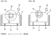
- FIG. 4A illustrates another variation of the cross-section of the printer 1 when the remaining amount of a roll of paper is large.
- FIG. 4B illustrates another variation of the cross-section of the printer 1 when the remaining amount of a roll of paper is small.
- FIG. 4A and FIG. 4B illustrate the cross-section of the printer 1 as viewed from the right in FIG. 1 .
- the roll of paper 10 is held by a shaft 14 penetrating through the center of the roll of paper 10, and both ends of the shaft 14 are rotatably supported by recess portions 3b of the inside holder 3.
- a roll of paper may be held along the curved shape of the inside holder 3 as illustrated in FIG. 1 without using the shaft 14.
- the mechanical switch 12 is located above the inside holder 3.
- the roll of paper 10 weighs down the inside holder 3, and the inside holder 3 compresses the springs 13. Accordingly, the mechanical switch 12 faces the inside holder 3 while being apart from the inside holder 3, and the mechanical switch 12 is thus off. Thus, no signal is output from the mechanical switch 12 to the microcomputer 5.
- the microcomputer 5 determines that the remaining amount of the roll of paper 10 is large.
- the restoring force of the spring 13 lifts up the inside holder 3.
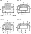
- FIG. 5A and FIG. 5C illustrate other variations of the cross-section of the printer 1 when the remaining amount of a roll of paper is large.
- FIG. 5B and FIG. 5D illustrate other variations of the cross-section of the printer 1 when the remaining amount of a roll of paper is small.
- FIG. 5A through FIG. 5D illustrate the cross-section of the printer 1 as viewed from the front in FIG. 1 .
- the mechanical switch 12 is located on the side surface, which faces the outside holder 2, of the inside holder 3.
- a penetration hole 2a illustrated in FIG. 5A and FIG. 5B or a recess portion 2b illustrated in FIG. 5C and FIG. 5D is formed in the outside holder 2.
- the mechanical switch 12 is located between the outside holder 2 and the side surface of the inside holder 3, and the mechanical switch 12 remains pressed. In this case, an ON signal is output from the mechanical switch 12 to the microcomputer 5, and the microcomputer 5 determines that the remaining amount of the roll of paper 10 is large.
- the microcomputer 5 determines that the remaining amount of the roll of paper 10 is small.
- the microcomputer 5 lights or blinks the LED 7 to notify the user of the near-end of a roll of paper.
- FIG. 6A and FIG. 6C are yet other variations of the cross-section of the printer 1 when the remaining amount of a roll of paper is large.
- FIG. 6B and FIG. 6D are yet other variations of the cross-section of the printer 1 when the remaining amount of a roll of paper is small.
- FIG. 6A through FIG. 6D illustrate the cross-section of the printer 1 as viewed from the front in FIG. 1 .
- a reflective optical sensor 15 as the first detection unit is provided instead of the mechanical switch 12.
- the optical sensor 15 is located on the outside holder 2 toward the inside holder 3, and is electrically connected to the microcomputer 5.
- the optical sensor 15 emits a light, receives a reflected light, and outputs a signal indicating the amount of light received to the microcomputer 5.
- the distance between the optical sensor 15 and the inside holder 3 is short, the amount of light received is large.
- the distance between the optical sensor 15 and the inside holder 3 is long, the amount of light received is small. Accordingly, when the amount of light received is equal to or greater than a threshold value, this means that the distance between the optical sensor 15 and the inside holder 3 is short and the inside holder 3 is weighed down with the roll of paper 10.
- the microcomputer 5 determines that the remaining amount of a roll of paper is large.
- the microcomputer 5 determines that the remaining amount of a roll of paper is small.
- the microcomputer 5 may calculate the distance between the optical sensor 15 and the inside holder 3 based on a signal indicating the amount of light received.
- the microcomputer 5 may determine that the remaining amount of a roll of paper is large when the calculated distance is less than a threshold value, and determine that the remaining amount of a roll of paper is small when the calculated distance is equal to or greater than the threshold value.
- the roll of paper 10 weighs down the inside holder 3
- the optical sensor 15 faces the inside holder 3, emits a light, receives a reflected light, and outputs a signal indicating the amount of light received to the microcomputer 5.
- the amount of light received by the optical sensor 15 is equal to or greater than the threshold value.
- the microcomputer 5 determines that the remaining amount of a roll of paper is large.
- the restoring force of the spring 13 lifts up the inside holder 3.
- the optical sensor 15 receives no reflected light or receives a reflected light from the outside holder 2 facing the optical sensor 15.
- the amount of light received by the optical sensor 15 is less than the threshold value. Accordingly, the microcomputer 5 determines that the remaining amount of the roll of paper 10 is small.
- the microcomputer 5 lights or blinks the LED 7, and notifies the user of the near-end of a roll of paper.
- steps may be formed on the side surface of the inside holder 3. More specifically, steps may be formed on the side surface of the inside holder 3 so that the width in the horizontal direction increases from the bottom to the top of the side surface.
- the step (position) of the inside holder 3 reflecting a light from the optical sensor 15 in FIG. 6C differs from that in FIG. 6D .
- the amount of light received is greater than that in FIG. 6D .
- the microcomputer 5 is able to appropriately determine whether the remaining amount of a roll of paper is large or small.
- the sensor level changes, and it becomes possible to detect the change in remaining amount of a roll of paper.
- FIG. 7A is a cross-sectional view of the printer 1 as viewed from the right in FIG. 1 .
- FIG. 7B illustrates yet another variation of the cross-section of the printer 1 when the remaining amount of a roll of paper is large.
- FIG. 7C illustrates yet another variation of the cross-section of the printer 1 when the remaining amount of a roll of paper is small.
- FIG. 7B and FIG. 7C illustrate the cross-section of the printer 1 as viewed from the front in FIG. 1 .
- a transmissive optical sensor 16 is located on the bottom plate 11.
- the optical sensor 16 is electrically connected to the microcomputer 5.
- the optical sensor 16 includes a light-emitting unit 16a that emits a light and a light-receiving unit 16b that receives the light emitted from the light-emitting unit 16a.
- the light-receiving unit 16b When receiving a light from the light-emitting unit 16a within a predetermined time period from the light emission, the light-receiving unit 16b outputs an ON signal to the microcomputer 5, and when not receiving a light from the light-emitting unit 16a within the predetermined time period from the light emission, outputs an OFF signal to the microcomputer 5.
- a protrusion portion 30 protruding downward is formed at the lower end of the inside holder 3.
- the protrusion portion 30 is configured so as to be located between the light-emitting unit 16a and the light-receiving unit 16b when the remaining amount of a roll of paper is large.
- the roll of paper 10 weighs down the inside holder 3, and the light-emitting unit 16a of the optical sensor 16 emits a light. Since the protrusion portion 30 is located between the light-emitting unit 16a and the light-receiving unit 16b and blocks the light from the light-emitting unit 16a, the light-receiving unit 16b does not receive the light from the light-emitting unit 16a and thus outputs an OFF signal to the microcomputer 5.
- the microcomputer 5 determines that the remaining amount of a roll of paper is large based on the off signal from the light-receiving unit 16b.
- the restoring force of the spring 13 lifts up the inside holder 3 and the protrusion portion 30.
- the protrusion portion 30 does not block a light from the light-emitting unit 16a, and the light-receiving unit 16b receives the light from the light-emitting unit 16a and outputs an ON signal to the microcomputer 5.
- the microcomputer 5 determines that the remaining amount of a roll of paper is small based on the ON signal from the light-receiving unit 16b.
- the microcomputer 5 lights or blinks the LED 7, and notifies the user of the near-end of a roll of paper.
- the printer 1 includes the inside holder 3 holding the roll of paper 10, the spring 13 supporting the inside holder 3 so that the inside holder 3 is slidable in the vertical direction, the mechanical switch 12 that detects whether the mechanical switch 12 is in contact with the inside holder 3, and the microcomputer 5 that detects the near-end of the roll of paper 10 based on the detection result by the mechanical switch 12. Accordingly, unlike the conventional technique, the near-end of the roll of paper 10 is detected based on the contact position or non-contact position with the inside holder 3 by the mechanical switch 12 without detecting the outside diameter of the roll of paper 10. Therefore, regardless of the state of the outside diameter of the roll of paper 10, the detection accuracy of the near-end of the roll of paper 10 is improved.
- the printer 1 includes the inside holder 3 that holds the roll of paper 10, the spring 13 that supports the inside holder 3 so that the inside holder 3 is slidable in the vertical direction, the optical sensor 15 that emits a light to the inside holder 3 and detects the amount of received reflected light by the inside holder 3, and the microcomputer 5 that detects the near-end of the roll of paper 10 based on the detection result by the optical sensor 15. Accordingly, unlike the conventional technique, the near-end of the roll of paper 10 is detected based on the amount of light received by the optical sensor 15 without detecting the outside diameter of the roll of paper 10. Therefore, regardless of the state of the outside diameter of the roll of paper 10, the detection accuracy of the near-end of the roll of paper 10 is improved.
- none of the mechanical switch 12 and the optical sensors 15 and 16 is in direct contact with the roll of paper 10. Thus, scratching or folding of the roll of paper 10 is prevented.
- the present embodiment uses the LED 7 for notification of the near-end, but the notification of the near-end may be executed by other methods. For example, notification of the near-end may be performed by data communication to a superior device connected to the printer 1.
Landscapes
- Engineering & Computer Science (AREA)
- Mechanical Engineering (AREA)
- Controlling Sheets Or Webs (AREA)
- Handling Of Continuous Sheets Of Paper (AREA)
- Controlling Rewinding, Feeding, Winding, Or Abnormalities Of Webs (AREA)
- Accessory Devices And Overall Control Thereof (AREA)
Abstract
Description
- Embodiments of the present invention relate to a printer.
- There has been conventionally known a sheet feeder having a function to detect the remaining amount of a roll of paper as disclosed in, for example, Japanese Patent Application Publication No.
2007-76849 - In addition, a thermal printer having a thermal print unit is widely used as a mobile printer, an ATM, a KIOSK terminal, or a convenience store payment terminal printer. In the case where the administrator cannot reside and the timing for replacing a roll of paper is limited like ATM, implementation of a mechanism for detecting the state where the remaining amount of paper is small, that is, the so-called near-end of a roll of paper is desired.
- There has been known a technique that detects the outside diameter of a roll of paper by attaching a switch or an optical sensor to the side surface or the bottom surface of a paper holder to detect the near-end of a roll of paper.
- As the remaining amount of a roll of paper decreases, the outside diameter of the roll of paper increases due to loosening of the roll of paper. Thus, with the technique that detects the outside diameter of a roll of paper, the detection accuracy of the near-end of the roll of paper may decrease due to the increase in outside diameter of the roll of paper.
- It is desirable to provide a printer that improves the detection accuracy of the near-end of a roll of paper regardless of the state of the outside diameter of the roll of paper.
- According to an embodiment of one aspect of the present invention, there is provided a printer (1) including: a holding member (3) configured to hold a roll of paper (10); an elastic member (13) configured to support the holding member (3) so that the holding member is slidable in a vertical direction; a first detection unit (12) configured to detect a position of the holding member (13); and a second detection unit (5) that detects a near-end of the roll of paper (10) based on a detection result by the first detection unit (13).
- Embodiments of the invention are set out, by way of example only, with reference to the following drawings, in which:
-
FIG. 1 is a perspective view of a printer in accordance with a present embodiment; -
FIG. 2A is a partial cross-sectional view taken along line A-A inFIG. 1 when the remaining amount of a roll of paper is large, andFIG. 2B is a partial cross-sectional view taken along line A-A inFIG. 1 when the remaining amount of a roll of paper is small; -
FIG. 3A illustrates a variation of the cross-section of the printer when the remaining amount of a roll of paper is large, andFIG. 3B illustrates a variation of the cross-section of the printer when the remaining amount of a roll of paper is small; -
FIG. 4A illustrates another variation of the cross-section of the printer when the remaining amount of a roll of paper is large, andFIG. 4B illustrates another variation of the cross-section of the printer when the remaining amount of a roll of paper is small; -
FIG. 5A and FIG. 5C illustrate other variations of the cross-section of the printer when the remaining amount of a roll of paper is large, andFIG. 5B and FIG. 5D illustrate other variations of the cross-section of the printer when the remaining amount of a roll of paper is small; -
FIG. 6A and FIG. 6C illustrate yet other variations of the cross-section of the printer when the remaining amount of a roll of paper is large, andFIG. 6B and FIG. 6D illustrate yet other variations of the cross-section of the printer when the remaining amount of a roll of paper is small; and -
FIG. 7A is a cross-sectional view of the printer as viewed from the right inFIG. 1 ,FIG. 7B illustrates yet another variation of the cross-section of the printer when the remaining amount of a roll of paper is large, andFIG. 7C illustrates yet another variation of the cross-section of the printer when the remaining amount of a roll of paper is small. - Hereinafter, embodiments of the present invention will be described with reference to the accompanying drawings.
-
FIG. 1 is a perspective view of a printer in accordance with a present embodiment.FIG. 2A is a cross-sectional view taken along line A-A inFIG. 1 when the remaining amount of a roll of paper is large.FIG. 2B is a cross-sectional view taken along line A-A inFIG. 1 when the remaining amount of a roll of paper is small. The front and rear, the top and bottom, and the right and left of the printer are defined as illustrated inFIG. 1 . - A
printer 1 illustrated inFIG. 1 is, for example, a thermal printer, and is installed in a mobile printer, an ATM, or a KIOSK terminal. Theprinter 1 includes: anoutside holder 2 that regulates the movement of a roll of paper in the right-and-left direction and holds the roll of paper; aninside holder 3 as a holding member that is slidable relative to theoutside holder 2 in the vertical direction and holds the roll of paper from below; a print unit 4 that includes a thermal head and a platen roller, which are not illustrated, and prints data on a roll of paper; amicrocomputer 5 as a second detection unit that controls operations of the print unit 4 and receives signals from a mechanical switch or optical sensor described later; and acircuit board 6 having themicrocomputer 5 mounted thereon and attached to the side surface of theoutside holder 2. Themicrocomputer 5 is coupled to anLED 7, and when detecting the near-end of a roll of paper, notifies the user of the near-end of the roll of paper by lighting or blinking theLED 7. The near-end of a roll of paper indicates the state in which the remaining amount of the roll of paper is below a predetermined threshold value, and indicates the state in which replacement of the roll of paper is recommended. - A roll of paper falls in a
space 8 surrounded by theoutside holder 2 and theinside holder 3, and is then held along the curved shape of theinside holder 3, but a roll of paper may be held by a shaft penetrating through the center of the roll of paper. When a roll of paper is held by a shaft, both ends of the shaft is rotatably supported by theoutside holder 2 or theinside holder 3. The structure of theprinter 1 inFIG. 1 is merely an example, and does not intend to suggest any limitation. -
FIG. 2A is a partial cross-sectional view taken along line A-A inFIG. 1 when the remaining amount of a roll of paper is large.FIG. 2B is a partial cross-sectional view taken along line A-A inFIG. 1 when the remaining amount of a roll of paper is small. - In
FIG. 2A and FIG. 2B , theinside holder 3 is located on abottom plate 11 of theprinter 1 throughsprings 13 as elastic members. Thesprings 13 allow theinside holder 3 to slide in the vertical direction. Thespring 13 is a coil spring, but may be a plate spring or a torsion coil spring. Alternatively, an elastic body such as rubber may be used instead of thespring 13. Theoutside holder 2 and thebottom plate 11 function as the chassis of theprinter 1. - A
mechanical switch 12 as a first detection unit is located under theinside holder 3 and on thebottom plate 11. Themechanical switch 12 is surrounded by theoutside holder 2, theinside holder 3, and thebottom plate 11, thus being less affected by dust or the like. Themechanical switch 12 has aprotrusion portion 12a that protrudes in one direction, and detects the position of theinside holder 3 in the vertical direction based on the up-and-down motion of theprotrusion portion 12a. - In the case illustrated in
FIG. 2A , as the remaining amount of a roll ofpaper 10 is large, the roll ofpaper 10 weighs down theinside holder 3, and theinside holder 3 thus compresses thesprings 13. In this case, the bottom surface of theinside holder 3 is in contact with theprotrusion portion 12a of themechanical switch 12, and presses theprotrusion portion 12a of themechanical switch 12. When theprotrusion portion 12a of themechanical switch 12 is pressed, an ON signal is output from themechanical switch 12 to themicrocomputer 5. Accordingly, themicrocomputer 5 determines that the remaining amount of the roll ofpaper 10 is large. - When the remaining amount of the roll of
paper 10 is small as illustrated inFIG. 2B , the restoring force of thespring 13 lifts up theinside holder 3. In this case, the bottom surface of theinside holder 3 separates from theprotrusion portion 12a of themechanical switch 12, and themechanical switch 12 is turned off. When themechanical switch 12 is turned off, no signal is output from themechanical switch 12 to themicrocomputer 5. Accordingly, themicrocomputer 5 determines that the remaining amount of the roll ofpaper 10 is small. That is, themicrocomputer 5 is able to detect the near-end of a roll of paper. In this case, themicrocomputer 5 lights or blinks theLED 7 to notify the user of the near-end of the roll of paper. - In
FIG. 2A and FIG. 2B , themechanical switch 12 is located under theinside holder 3 and on thebottom plate 11. However, themechanical switch 12 may be arranged, for example, on the outside holder 2 (i.e., the side surface of the printer 1) as illustrated inFIG. 3A and FIG. 3B . In this case, as illustrated inFIG. 3A , when the remaining amount of a roll of paper is large, the roll ofpaper 10 weighs down theinside holder 3, themechanical switch 12 is located between theoutside holder 2 and aside surface 3a of theinside holder 3, and themechanical switch 12 remains pressed. As illustrated inFIG. 3B , when the remaining amount of the roll ofpaper 10 is small, the restoring force of thespring 13 lifts up theinside holder 3, theside surface 3a of theinside holder 3 separates from themechanical switch 12, and themechanical switch 12 is turned off.FIG. 3A illustrates a variation of the cross-section of theprinter 1 when the remaining amount of a roll of paper is large.FIG. 3B illustrates a variation of the cross-section of theprinter 1 when the remaining amount of a roll of paper is small.FIG. 3A and FIG. 3B illustrate the cross-section taken along line A-A inFIG. 1 . - The
inside holder 3 may have a structure without lateral sides as illustrated inFIG. 2A and FIG. 2B , or a structure having lateral sides as illustrated inFIG. 3A and FIG. 3B . InFIG. 3A and FIG. 3B , themechanical switch 12 is located on theoutside holder 2 at the left side, but may be located on theoutside holder 2 at the right side. -
FIG. 4A illustrates another variation of the cross-section of theprinter 1 when the remaining amount of a roll of paper is large.FIG. 4B illustrates another variation of the cross-section of theprinter 1 when the remaining amount of a roll of paper is small.FIG. 4A and FIG. 4B illustrate the cross-section of theprinter 1 as viewed from the right inFIG. 1 . - In
FIG. 4A and FIG. 4B , the roll ofpaper 10 is held by ashaft 14 penetrating through the center of the roll ofpaper 10, and both ends of theshaft 14 are rotatably supported byrecess portions 3b of theinside holder 3. A roll of paper may be held along the curved shape of theinside holder 3 as illustrated inFIG. 1 without using theshaft 14. - In
FIG. 4A and FIG. 4B , themechanical switch 12 is located above theinside holder 3. As illustrated inFIG. 4A , when the remaining amount of a roll of paper is large, the roll ofpaper 10 weighs down theinside holder 3, and theinside holder 3 compresses thesprings 13. Accordingly, themechanical switch 12 faces theinside holder 3 while being apart from theinside holder 3, and themechanical switch 12 is thus off. Thus, no signal is output from themechanical switch 12 to themicrocomputer 5. In this case, themicrocomputer 5 determines that the remaining amount of the roll ofpaper 10 is large. As illustrated inFIG. 4B , when the remaining amount of the roll ofpaper 10 is small, the restoring force of thespring 13 lifts up theinside holder 3. In this case, a part of the upper surface of theinside holder 3 comes in contact with themechanical switch 12, and presses themechanical switch 12. When themechanical switch 12 is pressed, an ON signal is output from themechanical switch 12 to themicrocomputer 5, and themicrocomputer 5 determines that the remaining amount of the roll ofpaper 10 is small. Themicrocomputer 5 lights or blinks theLED 7 to notify the user of the near-end of the roll of paper. -
FIG. 5A and FIG. 5C illustrate other variations of the cross-section of theprinter 1 when the remaining amount of a roll of paper is large.FIG. 5B and FIG. 5D illustrate other variations of the cross-section of theprinter 1 when the remaining amount of a roll of paper is small.FIG. 5A through FIG. 5D illustrate the cross-section of theprinter 1 as viewed from the front inFIG. 1 . - In
FIG. 5A through FIG. 5D , themechanical switch 12 is located on the side surface, which faces theoutside holder 2, of theinside holder 3. Apenetration hole 2a illustrated inFIG. 5A and FIG. 5B or arecess portion 2b illustrated inFIG. 5C and FIG. 5D is formed in theoutside holder 2. As illustrated inFIG. 5A and FIG. 5C , when the remaining amount of a roll of paper is large, the roll ofpaper 10 weighs down theinside holder 3, themechanical switch 12 is located between theoutside holder 2 and the side surface of theinside holder 3, and themechanical switch 12 remains pressed. In this case, an ON signal is output from themechanical switch 12 to themicrocomputer 5, and themicrocomputer 5 determines that the remaining amount of the roll ofpaper 10 is large. - As illustrated in
FIG. 5B and FIG. 5D , as the remaining amount of the roll ofpaper 10 decreases, the restoring force of thespring 13 lifts up theinside holder 3, and themechanical switch 12 gets into thepenetration hole 2a or therecess portion 2b of the outside holder and is turned off. When themechanical switch 12 is turned off, no signal is output from themechanical switch 12 to themicrocomputer 5. Thus, themicrocomputer 5 determines that the remaining amount of the roll ofpaper 10 is small. Themicrocomputer 5 lights or blinks theLED 7 to notify the user of the near-end of a roll of paper. -
FIG. 6A and FIG. 6C are yet other variations of the cross-section of theprinter 1 when the remaining amount of a roll of paper is large.FIG. 6B and FIG. 6D are yet other variations of the cross-section of theprinter 1 when the remaining amount of a roll of paper is small.FIG. 6A through FIG. 6D illustrate the cross-section of theprinter 1 as viewed from the front inFIG. 1 . - In
FIG. 6A through FIG. 6D , a reflectiveoptical sensor 15 as the first detection unit is provided instead of themechanical switch 12. Theoptical sensor 15 is located on theoutside holder 2 toward theinside holder 3, and is electrically connected to themicrocomputer 5. - The
optical sensor 15 emits a light, receives a reflected light, and outputs a signal indicating the amount of light received to themicrocomputer 5. When the distance between theoptical sensor 15 and theinside holder 3 is short, the amount of light received is large. When the distance between theoptical sensor 15 and theinside holder 3 is long, the amount of light received is small. Accordingly, when the amount of light received is equal to or greater than a threshold value, this means that the distance between theoptical sensor 15 and theinside holder 3 is short and theinside holder 3 is weighed down with the roll ofpaper 10. Thus, themicrocomputer 5 determines that the remaining amount of a roll of paper is large. When the amount of light received is less than the threshold value, this means that the distance between theoptical sensor 15 and theinside holder 3 is long and theinside holder 3 is being lifted by the restoring force of thespring 13. Thus, themicrocomputer 5 determines that the remaining amount of a roll of paper is small. - The
microcomputer 5 may calculate the distance between theoptical sensor 15 and theinside holder 3 based on a signal indicating the amount of light received. Themicrocomputer 5 may determine that the remaining amount of a roll of paper is large when the calculated distance is less than a threshold value, and determine that the remaining amount of a roll of paper is small when the calculated distance is equal to or greater than the threshold value. - As illustrated in
FIG. 6A , when the remaining amount of a roll of paper is large, the roll ofpaper 10 weighs down theinside holder 3, theoptical sensor 15 faces theinside holder 3, emits a light, receives a reflected light, and outputs a signal indicating the amount of light received to themicrocomputer 5. In this case, the amount of light received by theoptical sensor 15 is equal to or greater than the threshold value. Thus, themicrocomputer 5 determines that the remaining amount of a roll of paper is large. - When the remaining amount of the roll of
paper 10 is small as illustrated inFIG. 6B , the restoring force of thespring 13 lifts up theinside holder 3. In this case, theoptical sensor 15 receives no reflected light or receives a reflected light from theoutside holder 2 facing theoptical sensor 15. Thus, the amount of light received by theoptical sensor 15 is less than the threshold value. Accordingly, themicrocomputer 5 determines that the remaining amount of the roll ofpaper 10 is small. Themicrocomputer 5 lights or blinks theLED 7, and notifies the user of the near-end of a roll of paper. - As illustrated in
FIG. 6C and FIG. 6D , steps may be formed on the side surface of theinside holder 3. More specifically, steps may be formed on the side surface of theinside holder 3 so that the width in the horizontal direction increases from the bottom to the top of the side surface. - The step (position) of the
inside holder 3 reflecting a light from theoptical sensor 15 inFIG. 6C differs from that inFIG. 6D . In the case ofFIG. 6C , since the distance between theoptical sensor 15 and theinside holder 3 is less than that inFIG. 6D , the amount of light received is greater than that inFIG. 6D . Thus, by setting a threshold value at a value between the amount of light received in the case ofFIG. 6C and the amount of light received in the case ofFIG. 6D , themicrocomputer 5 is able to appropriately determine whether the remaining amount of a roll of paper is large or small. In addition, by providing steps on the side surface of theinside holder 3 to change the reflection distance of a light from theoptical sensor 15, the sensor level changes, and it becomes possible to detect the change in remaining amount of a roll of paper. -
FIG. 7A is a cross-sectional view of theprinter 1 as viewed from the right inFIG. 1 .FIG. 7B illustrates yet another variation of the cross-section of theprinter 1 when the remaining amount of a roll of paper is large.FIG. 7C illustrates yet another variation of the cross-section of theprinter 1 when the remaining amount of a roll of paper is small.FIG. 7B and FIG. 7C illustrate the cross-section of theprinter 1 as viewed from the front inFIG. 1 . - As illustrated in
FIG. 7A through FIG. 7C , a transmissiveoptical sensor 16 is located on thebottom plate 11. Theoptical sensor 16 is electrically connected to themicrocomputer 5. Theoptical sensor 16 includes a light-emittingunit 16a that emits a light and a light-receivingunit 16b that receives the light emitted from the light-emittingunit 16a. When receiving a light from the light-emittingunit 16a within a predetermined time period from the light emission, the light-receivingunit 16b outputs an ON signal to themicrocomputer 5, and when not receiving a light from the light-emittingunit 16a within the predetermined time period from the light emission, outputs an OFF signal to themicrocomputer 5. - As illustrated in
FIG. 7A , aprotrusion portion 30 protruding downward is formed at the lower end of theinside holder 3. As illustrated inFIG. 7B , theprotrusion portion 30 is configured so as to be located between the light-emittingunit 16a and the light-receivingunit 16b when the remaining amount of a roll of paper is large. - As illustrated in
FIG. 7B , when the remaining amount of a roll of paper is large, the roll ofpaper 10 weighs down theinside holder 3, and the light-emittingunit 16a of theoptical sensor 16 emits a light. Since theprotrusion portion 30 is located between the light-emittingunit 16a and the light-receivingunit 16b and blocks the light from the light-emittingunit 16a, the light-receivingunit 16b does not receive the light from the light-emittingunit 16a and thus outputs an OFF signal to themicrocomputer 5. Themicrocomputer 5 determines that the remaining amount of a roll of paper is large based on the off signal from the light-receivingunit 16b. - As illustrated in
FIG. 7C , when the remaining amount of the roll ofpaper 10 is small, the restoring force of thespring 13 lifts up theinside holder 3 and theprotrusion portion 30. In this case, theprotrusion portion 30 does not block a light from the light-emittingunit 16a, and the light-receivingunit 16b receives the light from the light-emittingunit 16a and outputs an ON signal to themicrocomputer 5. Themicrocomputer 5 determines that the remaining amount of a roll of paper is small based on the ON signal from the light-receivingunit 16b. Themicrocomputer 5 lights or blinks theLED 7, and notifies the user of the near-end of a roll of paper. - As described above, the
printer 1 includes theinside holder 3 holding the roll ofpaper 10, thespring 13 supporting theinside holder 3 so that theinside holder 3 is slidable in the vertical direction, themechanical switch 12 that detects whether themechanical switch 12 is in contact with theinside holder 3, and themicrocomputer 5 that detects the near-end of the roll ofpaper 10 based on the detection result by themechanical switch 12. Accordingly, unlike the conventional technique, the near-end of the roll ofpaper 10 is detected based on the contact position or non-contact position with theinside holder 3 by themechanical switch 12 without detecting the outside diameter of the roll ofpaper 10. Therefore, regardless of the state of the outside diameter of the roll ofpaper 10, the detection accuracy of the near-end of the roll ofpaper 10 is improved. - The
printer 1 includes theinside holder 3 that holds the roll ofpaper 10, thespring 13 that supports theinside holder 3 so that theinside holder 3 is slidable in the vertical direction, theoptical sensor 15 that emits a light to theinside holder 3 and detects the amount of received reflected light by theinside holder 3, and themicrocomputer 5 that detects the near-end of the roll ofpaper 10 based on the detection result by theoptical sensor 15. Accordingly, unlike the conventional technique, the near-end of the roll ofpaper 10 is detected based on the amount of light received by theoptical sensor 15 without detecting the outside diameter of the roll ofpaper 10. Therefore, regardless of the state of the outside diameter of the roll ofpaper 10, the detection accuracy of the near-end of the roll ofpaper 10 is improved. - Furthermore, in the present embodiment, none of the
mechanical switch 12 and theoptical sensors paper 10. Thus, scratching or folding of the roll ofpaper 10 is prevented. - The present embodiment uses the
LED 7 for notification of the near-end, but the notification of the near-end may be executed by other methods. For example, notification of the near-end may be performed by data communication to a superior device connected to theprinter 1. - The present invention is not limited to the specifically disclosed embodiment and variations but may include other embodiments and variations without departing from the scope of the present invention.
Claims (5)
- A printer (1) comprising:a holding member (3) configured to hold a roll of paper (10);an elastic member (13) configured to support the holding member (3) so that the holding member is slidable in a vertical direction;a first detection unit (12) configured to detect a position of the holding member (13); anda second detection unit (5) that detects a near-end of the roll of paper (10) based on a detection result by the first detection unit (13).
- The printer according to claim 1, wherein
the first detection unit is located above the holding member (3), under the holding member (3), or at a location facing a side surface (3a) of the holding member (3). - The printer according to claim 1, further comprising
a chassis (2, 11) configured to hold the holding member (3) through the elastic member (13), wherein
the first detection unit (12) is located on a side surface, which faces the chassis, of the holding member (3), and
the chassis has a penetration hole (2a) or a recess portion (2b) at a position facing a position at which the first detection unit (12) is located when the first detection unit (12) detects a near-end of the roll of paper (10). - The printer according to claim 1, wherein
a side surface, which faces the first detection unit (15), of the holding member (3) has a step that makes a width of the holding member (3) in a horizontal direction increase toward a bottom or a top. - The printer according to claim 1, wherein
the first detection unit (12) includes a protrusion portion (12a) protruding in one direction, and detects a position of the holding member (3) in the vertical direction by the protrusion portion (12a).
Applications Claiming Priority (1)
| Application Number | Priority Date | Filing Date | Title |
|---|---|---|---|
| JP2017148403A JP2019026441A (en) | 2017-07-31 | 2017-07-31 | Printer |
Publications (1)
| Publication Number | Publication Date |
|---|---|
| EP3438027A1 true EP3438027A1 (en) | 2019-02-06 |
Family
ID=62495644
Family Applications (1)
| Application Number | Title | Priority Date | Filing Date |
|---|---|---|---|
| EP18175419.3A Withdrawn EP3438027A1 (en) | 2017-07-31 | 2018-05-31 | Printer |
Country Status (5)
| Country | Link |
|---|---|
| US (1) | US10525743B2 (en) |
| EP (1) | EP3438027A1 (en) |
| JP (1) | JP2019026441A (en) |
| KR (1) | KR20190013484A (en) |
| CN (1) | CN109319536A (en) |
Citations (3)
| Publication number | Priority date | Publication date | Assignee | Title |
|---|---|---|---|---|
| EP0649808A1 (en) * | 1993-10-21 | 1995-04-26 | Fujitsu Isotec Limited | Device for detecting near end state of a roll of paper |
| JP2007076849A (en) | 2005-09-15 | 2007-03-29 | Ricoh Co Ltd | Paper feeder |
| EP2514599A1 (en) * | 2009-12-17 | 2012-10-24 | Shandong New Beiyang Information Technology Co., Ltd. | Printer, web accommodating component thereof, and web exhaustion detecting mechanism |
Family Cites Families (8)
| Publication number | Priority date | Publication date | Assignee | Title |
|---|---|---|---|---|
| JPS5636837Y2 (en) * | 1976-02-24 | 1981-08-29 | ||
| JPH0589348A (en) | 1991-06-28 | 1993-04-09 | Sharp Corp | Vending machine product unloading device |
| JPH0589348U (en) * | 1991-08-27 | 1993-12-07 | 日本電気ホームエレクトロニクス株式会社 | Printer |
| JP2001048379A (en) | 1999-08-17 | 2001-02-20 | Nec Niigata Ltd | Paper feeder |
| JP2002193511A (en) * | 2000-12-27 | 2002-07-10 | Sato Corp | Printer paper feeder |
| US7549814B1 (en) | 2007-12-18 | 2009-06-23 | International Business Machines Corporation | Compact low paper sensor mechanism |
| CN104418143A (en) | 2013-08-20 | 2015-03-18 | 芯发威达电子(上海)有限公司 | Paper roll device with paper roll consumption detection function |
| CN204751635U (en) * | 2015-07-01 | 2015-11-11 | 浙江索凡胶粘制品有限公司 | A adjustable coiling mechanism for on coating machine |
-
2017
- 2017-07-31 JP JP2017148403A patent/JP2019026441A/en active Pending
-
2018
- 2018-05-31 EP EP18175419.3A patent/EP3438027A1/en not_active Withdrawn
- 2018-06-04 US US15/996,762 patent/US10525743B2/en not_active Expired - Fee Related
- 2018-07-06 KR KR1020180078577A patent/KR20190013484A/en not_active Ceased
- 2018-07-17 CN CN201810780318.4A patent/CN109319536A/en active Pending
Patent Citations (3)
| Publication number | Priority date | Publication date | Assignee | Title |
|---|---|---|---|---|
| EP0649808A1 (en) * | 1993-10-21 | 1995-04-26 | Fujitsu Isotec Limited | Device for detecting near end state of a roll of paper |
| JP2007076849A (en) | 2005-09-15 | 2007-03-29 | Ricoh Co Ltd | Paper feeder |
| EP2514599A1 (en) * | 2009-12-17 | 2012-10-24 | Shandong New Beiyang Information Technology Co., Ltd. | Printer, web accommodating component thereof, and web exhaustion detecting mechanism |
Also Published As
| Publication number | Publication date |
|---|---|
| KR20190013484A (en) | 2019-02-11 |
| US20190030926A1 (en) | 2019-01-31 |
| JP2019026441A (en) | 2019-02-21 |
| US10525743B2 (en) | 2020-01-07 |
| CN109319536A (en) | 2019-02-12 |
Similar Documents
| Publication | Publication Date | Title |
|---|---|---|
| US5915690A (en) | Adjustable low paper sensor | |
| US6599041B1 (en) | Sheet movement sensor | |
| US7507045B1 (en) | Multiple attitude low paper sensor mechanism | |
| EP3438027A1 (en) | Printer | |
| KR20080016322A (en) | Paper size sensing device and image forming apparatus having same | |
| JP6819069B2 (en) | Image forming device | |
| US20190263151A1 (en) | Printer | |
| EP3238983B1 (en) | Seating detection device | |
| JP2005349746A (en) | Printer and control method thereof | |
| US9770923B2 (en) | Detector apparatus for detecting near end of roll paper | |
| KR100233119B1 (en) | Apparatus for detecting paper of printer | |
| JP6812915B2 (en) | Image forming device | |
| CN111847025B (en) | Business machine with media quantity sensing function | |
| JP2011051158A (en) | Thermal printer | |
| CN214149142U (en) | Detection mechanism for paper size of printer | |
| JP2011056773A (en) | Thermal printer | |
| KR100485804B1 (en) | Paper size sensing apparatus for printer | |
| CN216001876U (en) | Printing apparatus | |
| KR100437119B1 (en) | Printer having device for sensing size of paper | |
| KR19980063849U (en) | Remaining paper detection device of paper cassette | |
| JP2021123019A (en) | Image recording device | |
| JPH0891627A (en) | Paper remaining amount detecting device in paper feeding device | |
| JP2002254676A (en) | Ink jet recording device | |
| KR100286804B1 (en) | Head feed distance adjusting device of dot printer | |
| KR20060127669A (en) | Image Forming Device |
Legal Events
| Date | Code | Title | Description |
|---|---|---|---|
| PUAI | Public reference made under article 153(3) epc to a published international application that has entered the european phase |
Free format text: ORIGINAL CODE: 0009012 |
|
| STAA | Information on the status of an ep patent application or granted ep patent |
Free format text: STATUS: THE APPLICATION HAS BEEN PUBLISHED |
|
| AK | Designated contracting states |
Kind code of ref document: A1 Designated state(s): AL AT BE BG CH CY CZ DE DK EE ES FI FR GB GR HR HU IE IS IT LI LT LU LV MC MK MT NL NO PL PT RO RS SE SI SK SM TR |
|
| AX | Request for extension of the european patent |
Extension state: BA ME |
|
| STAA | Information on the status of an ep patent application or granted ep patent |
Free format text: STATUS: REQUEST FOR EXAMINATION WAS MADE |
|
| 17P | Request for examination filed |
Effective date: 20190805 |
|
| RBV | Designated contracting states (corrected) |
Designated state(s): AL AT BE BG CH CY CZ DE DK EE ES FI FR GB GR HR HU IE IS IT LI LT LU LV MC MK MT NL NO PL PT RO RS SE SI SK SM TR |
|
| STAA | Information on the status of an ep patent application or granted ep patent |
Free format text: STATUS: THE APPLICATION HAS BEEN WITHDRAWN |
|
| 18W | Application withdrawn |
Effective date: 20200722 |