EP3437944A1 - Vehicle brake hydraulic control device - Google Patents
Vehicle brake hydraulic control device Download PDFInfo
- Publication number
- EP3437944A1 EP3437944A1 EP17774020.6A EP17774020A EP3437944A1 EP 3437944 A1 EP3437944 A1 EP 3437944A1 EP 17774020 A EP17774020 A EP 17774020A EP 3437944 A1 EP3437944 A1 EP 3437944A1
- Authority
- EP
- European Patent Office
- Prior art keywords
- pressure increasing
- control
- time
- pressure
- road surface
- Prior art date
- Legal status (The legal status is an assumption and is not a legal conclusion. Google has not performed a legal analysis and makes no representation as to the accuracy of the status listed.)
- Granted
Links
Images


Classifications
-
- B—PERFORMING OPERATIONS; TRANSPORTING
- B60—VEHICLES IN GENERAL
- B60T—VEHICLE BRAKE CONTROL SYSTEMS OR PARTS THEREOF; BRAKE CONTROL SYSTEMS OR PARTS THEREOF, IN GENERAL; ARRANGEMENT OF BRAKING ELEMENTS ON VEHICLES IN GENERAL; PORTABLE DEVICES FOR PREVENTING UNWANTED MOVEMENT OF VEHICLES; VEHICLE MODIFICATIONS TO FACILITATE COOLING OF BRAKES
- B60T8/00—Arrangements for adjusting wheel-braking force to meet varying vehicular or ground-surface conditions, e.g. limiting or varying distribution of braking force
- B60T8/17—Using electrical or electronic regulation means to control braking
- B60T8/176—Brake regulation specially adapted to prevent excessive wheel slip during vehicle deceleration, e.g. ABS
- B60T8/1763—Brake regulation specially adapted to prevent excessive wheel slip during vehicle deceleration, e.g. ABS responsive to the coefficient of friction between the wheels and the ground surface
- B60T8/17636—Microprocessor-based systems
-
- B—PERFORMING OPERATIONS; TRANSPORTING
- B60—VEHICLES IN GENERAL
- B60T—VEHICLE BRAKE CONTROL SYSTEMS OR PARTS THEREOF; BRAKE CONTROL SYSTEMS OR PARTS THEREOF, IN GENERAL; ARRANGEMENT OF BRAKING ELEMENTS ON VEHICLES IN GENERAL; PORTABLE DEVICES FOR PREVENTING UNWANTED MOVEMENT OF VEHICLES; VEHICLE MODIFICATIONS TO FACILITATE COOLING OF BRAKES
- B60T8/00—Arrangements for adjusting wheel-braking force to meet varying vehicular or ground-surface conditions, e.g. limiting or varying distribution of braking force
- B60T8/17—Using electrical or electronic regulation means to control braking
- B60T8/172—Determining control parameters used in the regulation, e.g. by calculations involving measured or detected parameters
-
- B—PERFORMING OPERATIONS; TRANSPORTING
- B60—VEHICLES IN GENERAL
- B60T—VEHICLE BRAKE CONTROL SYSTEMS OR PARTS THEREOF; BRAKE CONTROL SYSTEMS OR PARTS THEREOF, IN GENERAL; ARRANGEMENT OF BRAKING ELEMENTS ON VEHICLES IN GENERAL; PORTABLE DEVICES FOR PREVENTING UNWANTED MOVEMENT OF VEHICLES; VEHICLE MODIFICATIONS TO FACILITATE COOLING OF BRAKES
- B60T8/00—Arrangements for adjusting wheel-braking force to meet varying vehicular or ground-surface conditions, e.g. limiting or varying distribution of braking force
- B60T8/17—Using electrical or electronic regulation means to control braking
- B60T8/176—Brake regulation specially adapted to prevent excessive wheel slip during vehicle deceleration, e.g. ABS
- B60T8/1761—Brake regulation specially adapted to prevent excessive wheel slip during vehicle deceleration, e.g. ABS responsive to wheel or brake dynamics, e.g. wheel slip, wheel acceleration or rate of change of brake fluid pressure
-
- B—PERFORMING OPERATIONS; TRANSPORTING
- B60—VEHICLES IN GENERAL
- B60T—VEHICLE BRAKE CONTROL SYSTEMS OR PARTS THEREOF; BRAKE CONTROL SYSTEMS OR PARTS THEREOF, IN GENERAL; ARRANGEMENT OF BRAKING ELEMENTS ON VEHICLES IN GENERAL; PORTABLE DEVICES FOR PREVENTING UNWANTED MOVEMENT OF VEHICLES; VEHICLE MODIFICATIONS TO FACILITATE COOLING OF BRAKES
- B60T8/00—Arrangements for adjusting wheel-braking force to meet varying vehicular or ground-surface conditions, e.g. limiting or varying distribution of braking force
- B60T8/17—Using electrical or electronic regulation means to control braking
- B60T8/176—Brake regulation specially adapted to prevent excessive wheel slip during vehicle deceleration, e.g. ABS
- B60T8/1763—Brake regulation specially adapted to prevent excessive wheel slip during vehicle deceleration, e.g. ABS responsive to the coefficient of friction between the wheels and the ground surface
-
- B—PERFORMING OPERATIONS; TRANSPORTING
- B60—VEHICLES IN GENERAL
- B60T—VEHICLE BRAKE CONTROL SYSTEMS OR PARTS THEREOF; BRAKE CONTROL SYSTEMS OR PARTS THEREOF, IN GENERAL; ARRANGEMENT OF BRAKING ELEMENTS ON VEHICLES IN GENERAL; PORTABLE DEVICES FOR PREVENTING UNWANTED MOVEMENT OF VEHICLES; VEHICLE MODIFICATIONS TO FACILITATE COOLING OF BRAKES
- B60T8/00—Arrangements for adjusting wheel-braking force to meet varying vehicular or ground-surface conditions, e.g. limiting or varying distribution of braking force
- B60T8/17—Using electrical or electronic regulation means to control braking
- B60T8/176—Brake regulation specially adapted to prevent excessive wheel slip during vehicle deceleration, e.g. ABS
- B60T8/1764—Regulation during travel on surface with different coefficients of friction, e.g. between left and right sides, mu-split or between front and rear
-
- B—PERFORMING OPERATIONS; TRANSPORTING
- B60—VEHICLES IN GENERAL
- B60T—VEHICLE BRAKE CONTROL SYSTEMS OR PARTS THEREOF; BRAKE CONTROL SYSTEMS OR PARTS THEREOF, IN GENERAL; ARRANGEMENT OF BRAKING ELEMENTS ON VEHICLES IN GENERAL; PORTABLE DEVICES FOR PREVENTING UNWANTED MOVEMENT OF VEHICLES; VEHICLE MODIFICATIONS TO FACILITATE COOLING OF BRAKES
- B60T8/00—Arrangements for adjusting wheel-braking force to meet varying vehicular or ground-surface conditions, e.g. limiting or varying distribution of braking force
- B60T8/32—Arrangements for adjusting wheel-braking force to meet varying vehicular or ground-surface conditions, e.g. limiting or varying distribution of braking force responsive to a speed condition, e.g. acceleration or deceleration
- B60T8/34—Arrangements for adjusting wheel-braking force to meet varying vehicular or ground-surface conditions, e.g. limiting or varying distribution of braking force responsive to a speed condition, e.g. acceleration or deceleration having a fluid pressure regulator responsive to a speed condition
- B60T8/343—Systems characterised by their lay-out
- B60T8/344—Hydraulic systems
-
- B—PERFORMING OPERATIONS; TRANSPORTING
- B60—VEHICLES IN GENERAL
- B60T—VEHICLE BRAKE CONTROL SYSTEMS OR PARTS THEREOF; BRAKE CONTROL SYSTEMS OR PARTS THEREOF, IN GENERAL; ARRANGEMENT OF BRAKING ELEMENTS ON VEHICLES IN GENERAL; PORTABLE DEVICES FOR PREVENTING UNWANTED MOVEMENT OF VEHICLES; VEHICLE MODIFICATIONS TO FACILITATE COOLING OF BRAKES
- B60T2210/00—Detection or estimation of road or environment conditions; Detection or estimation of road shapes
- B60T2210/10—Detection or estimation of road conditions
- B60T2210/12—Friction
-
- B—PERFORMING OPERATIONS; TRANSPORTING
- B60—VEHICLES IN GENERAL
- B60T—VEHICLE BRAKE CONTROL SYSTEMS OR PARTS THEREOF; BRAKE CONTROL SYSTEMS OR PARTS THEREOF, IN GENERAL; ARRANGEMENT OF BRAKING ELEMENTS ON VEHICLES IN GENERAL; PORTABLE DEVICES FOR PREVENTING UNWANTED MOVEMENT OF VEHICLES; VEHICLE MODIFICATIONS TO FACILITATE COOLING OF BRAKES
- B60T2210/00—Detection or estimation of road or environment conditions; Detection or estimation of road shapes
- B60T2210/10—Detection or estimation of road conditions
- B60T2210/12—Friction
- B60T2210/124—Roads with different friction levels
-
- G—PHYSICS
- G01—MEASURING; TESTING
- G01N—INVESTIGATING OR ANALYSING MATERIALS BY DETERMINING THEIR CHEMICAL OR PHYSICAL PROPERTIES
- G01N19/00—Investigating materials by mechanical methods
- G01N19/02—Measuring coefficient of friction between materials
Definitions
- the present invention relates to a brake fluid pressure control device for a vehicle to determine changes in a frictional coefficient of a road surface on which the vehicle is travelling.
- An antilock braking system is a device to avoid locking of wheels.
- ABS antilock braking system
- a technique for determining whether a road surface on which a motorcycle is travelling has changed to a road surface with a high frictional coefficient from a road surface with a low frictional coefficient (whether a ⁇ jump has occurred) is known in, for example, Patent Literature Document 1.
- Patent Literature Document 1 Japanese Patent Application Laid-Open Publication No. Hei 5-105066
- An object of the present invention is to provide a brake fluid pressure control device for a vehicle that can accurately determine, with a simple method, whether a frictional coefficient of a road surface on which a vehicle is travelling has changed (whether the ⁇ jump has occurred or not).
- the invention according to claim 1 is directed to a brake fluid pressure control device for a vehicle, configured to be able to perform fluid pressure control for controlling brake fluid pressure acting on a wheel brake by repeating a control cycle including, at least, pressure increasing control and pressure reducing control.
- the brake fluid pressure control device is configured to determine whether pressure increasing time of current pressure increasing control exceeds determination time, which is set based on pressure increasing time of past pressure increasing control, during the fluid pressure control.
- the brake fluid pressure control device is configured to make a determination that a road surface on which the vehicle is travelling has changed to a road surface with a high frictional coefficient from a road surface with a low frictional coefficient if the pressure increasing time of the current pressure increasing control exceeds the determination time.
- the invention according to claim 2 is directed to the brake fluid pressure control device for a vehicle of claim 1, wherein a pressure increasing rate is altered to a higher value in the current pressure increasing control if the pressure increasing time of the current pressure increasing control reaches prescribed time that is shorter than the determination time.
- the invention according to claim 3 is directed to the brake fluid pressure control device for a vehicle of claim 1 or 2, wherein the determination time is set based on the pressure increasing time of a predetermined number of past pressure increasing control immediately prior to the current pressure increasing control.
- the invention according to claim 4 is directed to the brake fluid pressure control device for a vehicle of claim 3, wherein the determination time is set by adding a predetermined offset value to a maximum value of the pressure increasing time among a predetermined number of past pressure increasing control immediately prior to the current pressure increasing control.
- the brake fluid pressure control device makes a determination that the vehicle's traveling road surface has changed to a road surface with a high frictional coefficient from a road surface with a low frictional coefficient if the pressure increasing time of the current pressure increasing control exceeds the determination time.
- the pressure increasing rate of the current pressure increasing control when the pressure increasing time of the current pressure increasing control reaches the prescribed time, which is shorter than the determination time, the pressure increasing rate is altered to a higher value in the current pressure increasing control. Because the pressure increasing rate is raised to determine the occurrence of the ⁇ jump at the stage (point) prior to reaching the determination time, the lock-equivalent-fluid-pressure becomes considerably high if the change from the road surface with the low frictional coefficient to the road surface with the high frictional coefficient has actually occurred (if the ⁇ jump has occurred). Thus, the current pressure increasing control continues for a while even if the pressure increasing rate is raised. As a result, the pressure increasing time of the current pressure increasing control exceeds the determination time, and it is determined that the ⁇ jump has occurred.
- the brake fluid pressure will quickly reach the lock-equivalent-fluid-pressure upon raising the pressure increasing rate.
- the pressure increasing time of the current pressure increasing control does not exceed the determination time, and it is not determined that the ⁇ jump has occurred. For example, in a situation that the pressure increasing time becomes longer for some reasons although the ⁇ jump has not actually occurred, it is possible to avoid erroneous determination by intentionally raising the pressure increasing rate as described above, and to further improve the accuracy of the ⁇ jump determination.
- the determination time is set based on the pressure increasing time of a predetermined number of past pressure increasing control immediately prior to the current pressure increasing control.
- the determination time is set by adding the predetermined offset value to the maximum value of the pressure increasing time among a predetermined number of past pressure increasing control immediately prior to the current pressure increasing control.
- a brake fluid pressure control device 10 for a vehicle is configured to appropriately control a braking force (brake fluid pressure) applied onto wheels of the vehicle.
- a braking force brake fluid pressure
- the brake fluid pressure control device is mounted on a bar handle vehicle, and applied on a front wheel of, for example, a two-wheel vehicle.
- the brake fluid pressure control device for a vehicle 10 includes, as its major elements, a fluid pressure unit 100, which has fluid passages (brake fluid passages) and various parts, and a control device 200 to control various parts in the fluid pressure unit 100.
- the fluid pressure unit 100 is arranged between a master cylinder 12, which serves as a fluid pressure source, and a wheel brake 14.
- the fluid pressure unit 100 includes an inlet control valve 15 (control valve means 15), which is a normally open solenoid valve disposed on a fluid pressure passage from the master cylinder 12 to the wheel brake 14, an outlet control valve 16 (control valve means 16), which is a normally closed solenoid valve disposed on the fluid pressure passage from the master cylinder 12 to the wheel brake 14, a reservoir 13 to temporarily reserve the working fluid, a check valve 18 arranged in parallel to the inlet control valve 15 to only admit the flow of the fluid toward the master cylinder 12, a pump part 21 to discharge the working fluid from the reservoir 13 toward the master cylinder 12, and an actuator (motor) 22 to drive (actuate) the pump part 21.
- control valve means 15 which is a normally open solenoid valve disposed on a fluid pressure passage from the master cylinder 12 to the wheel brake 14
- outlet control valve 16 control valve means 16
- reservoir 13 to temporarily reserve the working fluid
- a check valve 18 arranged in parallel to the inlet control valve 15 to only admit the flow of the fluid toward the master cylinder 12, a
- the control device 200 includes a control device 30 configured to control the actuation of the actuator 22, and control opening and closing of the inlet control valve 15 and the outlet control valve 16.
- the control device 200 also includes a determination device 31 configured to determine whether the road surface on which the vehicle is traveling has changed from a road surface with a low frictional coefficient to a road surface with a high frictional coefficient (whether the ⁇ jump has taken placed).
- a wheel speed sensor 25 configured to detect the wheel speed of the wheel 23 is connected to the control device 200.
- the wheel speed is obtained by the determination device 31, and the estimated vehicle body speed is calculated on the basis of the wheel speed.
- a signal that represents the ⁇ jump determination, which is prepared by the determination device 31, a signal that represents the wheel speed, and a signal that represents the estimated vehicle body speed are transmitted to the control device 30, and the control device 30 performs ABS control and other processing, depending upon the result of the ⁇ jump determination. Therefore, it is possible to improve qualities of the control such as the ABS control.
- the brake fluid pressure control device for a vehicle 10 has a function to switch between a normal state during the normal braking and states (reduced-pressure state, a holding state, and an increased-pressure state) during the ABS control.
- the master cylinder 12 communicates with the wheel brake 14 (the inlet control valve 15 is open), and the wheel brake 14 is disconnected from the reservoir 13 (the outlet control valve 16 is closed).
- the working fluid pressure is applied to the wheel brake 14 from the master cylinder 12 through the inlet control valve 15 to brake the wheel.
- the control device 200 switches among the reduced-pressure state, the holding state and the increased-pressure state so as to perform the ABS control.
- the current flows to the inlet control valve 15 and the outlet control valve 16 such that the master cylinder 12 is disconnected from the wheel brake 14 (the inlet control valve 15 is closed), and the wheel brake 14 communicates with the reservoir 13 (the outlet control valve 16 is open).
- the working fluid flowing to the wheel brake 14 is released to the reservoir 13 through the outlet control valve 16, and therefore the working fluid pressure acting on the wheel brake 14 is reduced.
- the current flows to the inlet control valve 15 only, the master cylinder 12 is disconnected from the wheel brake 14, and the wheel brake 14 is disconnected from the reservoir 13 (the inlet control valve 15 and the outlet control valve 16 are closed).
- the working fluid is confined in the fluid passage closed by the wheel brake 14, the inlet control valve 15 and the outlet control valve 16, and the working fluid pressure acting on the wheel brake is maintained at a constant value.
- the feeding of the current to the inlet control valve 15 and the outlet control valve 16 is halted, the master cylinder 12 communicates with the wheel brake 14 (the inlet control valve 15 is open), and the wheel brake 14 is disconnected from the reservoir 13 (the outlet control valve 16 is closed).
- the fluid pressure of the wheel brake 14 is increased by the working fluid pressure from the master cylinder 12.
- the control device 200 activates the actuator 22 so that the pump 21 is activated. Accordingly, the working fluid, which is temporarily reserved in the reservoir 13, is caused to return toward the master cylinder 12.
- the brake fluid pressure control device for a vehicle 10 can perform the fluid pressure control on the brake fluid pressure that acts on the wheel brake 14 by repeating the pressure increasing control, including the control on the reduced-pressure state, the holding state and the increased-pressure state.
- a determination device for determining whether the road surface on which the vehicle is traveling has changed from a road surface with a low frictional coefficient (may be referred to as a low ⁇ road) to a road surface with a high frictional coefficient (may be referred to as a high ⁇ road) (whether the ⁇ jump has taken placed) will be described.
- FIG. 2A shows a correlation diagram between the time and the speed during the ABS control.
- the solid line indicates the wheel speed
- the imaginary line indicates the estimated speed of the vehicle.
- Tn represents the pressure increasing time of the pressure increasing control in the current control cycle (current pressure increasing control)
- Tn-1 represents the pressure increasing time of the pressure increasing control in a control cycle of one-cycle-before the current control cycle
- Tn-2 represents the pressure increasing time of the pressure increasing control in a control cycle of two-cycles-before the current control cycle
- Tn-3 represents the pressure increasing time of the pressure increasing control in a control cycle of three-cycles-before the current control cycle.
- the wheel speed gradually decreases as a whole, and the estimated speed of the vehicle also gradually decreases by repeating the control cycle including the increased-pressure state, the holding state and the reduced-pressure state of the brake fluid pressure.
- the road surface on which the vehicle is travelling is a low ⁇ road up to the time t13.
- the road surface on which the vehicle is travelling changes to a high ⁇ road from the low ⁇ road.
- FIG. 2A shows the wheel speed
- FIG. 2B shows the brake fluid pressure
- the brake fluid pressure P1 is pressure at which the wheel tends to lock when the traveling road surface is the low ⁇ road (this pressure may be referred to as low- ⁇ -road lock-equivalent fluid pressure)
- the brake fluid pressure P2 is pressure at which the wheel tends to lock when the traveling road surface is the high ⁇ road (this pressure may be referred to as high- ⁇ -road lock-equivalent pressure).
- the brake fluid pressure is lowered by the pressure reducing control upon the brake fluid pressure reaching the low- ⁇ -road lock-equivalent fluid pressure (time t1, t4, t7, t10).
- the brake fluid pressure is maintained at a constant value by the holding control (time t2, t5, t8, t11).
- the brake fluid pressure is raised by the pressure increasing control (time t3, t6, t9, t12). Such cycle of control is repeated.
- the traveling road surface is a low ⁇ road up to a certain point in time (time t13) in the current control cycle Cn. After that point in the current control cycle Cn, the road surface on which the vehicle is travelling changes to a high ⁇ road.
- the traveling road surface is the high ⁇ road, the brake fluid pressure is increased until the brake fluid pressure reaches the-high- ⁇ -road lock-equivalent fluid pressure P2, which is greater than low- ⁇ -road lock-equivalent fluid pressure P1.
- the determination device 31 reads the stored pressure increasing time Tn-3, Tn-2 and Tn-1 in the three immediately preceding pressure increasing control at Step 01 (Step is abbreviated to ST hereinafter).
- the maximum value among the pressure increasing time Tn-3, Tn-2 and Tn-1 is taken as Tmax.
- the control device makes a determination that the road surface on which the vehicle is travelling has changed to the road surface with the high frictional coefficient from the road surface with the low frictional coefficient.
- the lock-equivalent-fluid-pressure becomes considerably high if the ⁇ jump has actually occurred (the change from the road surface with the low frictional coefficient to the road surface with the high frictional coefficient has actually occurred).
- the pressure increasing rate is raised, the current pressure increasing control continues for a while.
- the pressure increasing time of the current pressure increasing control exceeds the determination time, and it is determined that the ⁇ jump has occurred.
- the brake fluid pressure will quickly reach the lock-equivalent-fluid-pressure upon raising the pressure increasing rate.
- the pressure increasing time of the current pressure increasing control does not exceed the determination time, and the determination of the occurrence of the ⁇ jump is not made.
- the pressure increasing time becomes longer for some reasons although the ⁇ jump has not actually occurred, it is possible to avoid erroneous determination by intentionally raising the pressure increasing rate as described above, and further improve the accuracy of the ⁇ jump determination.
- the determination time is set on the basis of the three pressure increasing time of the pressure increasing control in the three immediately preceding control cycles in the embodiment, the present invention is not limited to this.
- the determination time may be set on the basis of arbitrary pressure increasing time of the past pressure increasing control, e.g., the single or two pressure increasing time in the single or two immediately preceding control cycle, the five or more pressure increasing time in the five or more immediately preceding control cycles, or the three pressure increasing time in the three control cycles immediately prior to the immediately preceding control cycle.
- the determination time is decided by adding the predetermined offset to the maximum value of the pressure increasing time among a predetermined number of pressure increasing control immediately prior to the current pressure increasing control in the embodiment, the present invention is not limited to this.
- the determination time may be decided by adding a predetermined offset value to an average value of the pressure increasing time in a predetermined number of past pressure increasing control.
- the determination time may be decided by adding the offset value to the above-mentioned maximum value, the above-mentioned average value or a value of arbitrary pressure increasing control, the present invention is not limited to them.
- the determination time may be decided by multiplying the above-mentioned maximum value, the above-mentioned average value or the value of arbitrary pressure increasing control by a predetermined coefficient such as 1.1 or 1.2.
- FIGS. 4A and 4B are views useful to describe a modification to the embodiment of FIGS. 2A and 2B .
- the modification is different from the above-described embodiment in that the pressure increasing rate is raised when the prescribed time Tth2, which is shorter than the determination time Tth1, is reached in the current control cycle.
- the brake fluid pressure is reduced by the pressure reducing control upon the brake fluid pressure reaching the low- ⁇ -road lock-equivalent-liquid-pressure (time t21, t24, t27, t30).
- the brake fluid pressure is maintained at a constant value by the holding control (t22, t25, t28, t31).
- the brake fluid pressure is increased by the pressure increasing control (time t23, t26, t29, t32). Such cycle of control is repeated.
- the traveling road surface is the low ⁇ road up to a certain point in time (time t33) in the current control cycle Cn. After that point in the current control cycle Cn, the road surface on which the vehicle is travelling changes to the high ⁇ road.
- the travelling road surface is the high ⁇ road, the fluid pressure is increased until the fluid pressure reaches the high- ⁇ -road lock-equivalent-liquid-pressure P2, which is greater than the low- ⁇ -road lock-equivalent-liquid-pressure P1.
- the lock-equivalent-fluid-pressure becomes considerably high if the ⁇ jump has actually occurred (the change from the road surface with the low frictional coefficient to the road surface with the high frictional coefficient has actually occurred).
- the pressure increasing rate is raised, the current pressure increasing control continues for a while.
- the pressure increasing time of the current pressure increasing control exceeds the determination time, and it is determined that the ⁇ jump has occurred.
- the brake fluid pressure will quickly reach the lock-equivalent-fluid-pressure upon raising the pressure increasing rate.
- the pressure increasing time of the current pressure increasing control does not exceed the determination time, and the determination of the occurrence of the ⁇ jump is not made.
- the pressure increasing time becomes longer for some reasons although the ⁇ jump has not actually occurred, it is possible to avoid erroneous determination by intentionally raising the pressure increasing rate as described above, and further improve the accuracy of the ⁇ jump determination.
- the wheel brake fluid pressure control device may be disposed only on the front wheel or both of the wheels.
- the present invention is advantageously applied to the brake fluid pressure control device mounted on the motorcycle.
Landscapes
- Engineering & Computer Science (AREA)
- Transportation (AREA)
- Mechanical Engineering (AREA)
- Physics & Mathematics (AREA)
- Fluid Mechanics (AREA)
- Microelectronics & Electronic Packaging (AREA)
- Regulating Braking Force (AREA)
Abstract
Description
- The present invention relates to a brake fluid pressure control device for a vehicle to determine changes in a frictional coefficient of a road surface on which the vehicle is travelling.
- An antilock braking system (ABS) is a device to avoid locking of wheels. For example, a technique for determining whether a road surface on which a motorcycle is travelling has changed to a road surface with a high frictional coefficient from a road surface with a low frictional coefficient (whether a µ jump has occurred) is known in, for example,
Patent Literature Document 1. - In the brake fluid pressure control of
Patent Literature Document 1, an estimated vehicle body deceleration in a previous instance (previous control cycle) is compared to an estimated vehicle body deceleration in the current instance (current control cycle) to determine whether or not the µ jump has occurred. - In order to accurately determine the µ jump using the estimated vehicle body deceleration, however, high accuracy is also required to the estimation of the vehicle body deceleration. Thus, the processing may become complicated. In view of this, there is a demand for a technique that can accurately determine the µ jump with a simple method.
- Patent Literature Document 1: Japanese Patent Application Laid-Open Publication No.
Hei 5-105066 - An object of the present invention is to provide a brake fluid pressure control device for a vehicle that can accurately determine, with a simple method, whether a frictional coefficient of a road surface on which a vehicle is travelling has changed (whether the µ jump has occurred or not).
- The invention according to
claim 1 is directed to a brake fluid pressure control device for a vehicle, configured to be able to perform fluid pressure control for controlling brake fluid pressure acting on a wheel brake by repeating a control cycle including, at least, pressure increasing control and pressure reducing control. The brake fluid pressure control device is configured to determine whether pressure increasing time of current pressure increasing control exceeds determination time, which is set based on pressure increasing time of past pressure increasing control, during the fluid pressure control. The brake fluid pressure control device is configured to make a determination that a road surface on which the vehicle is travelling has changed to a road surface with a high frictional coefficient from a road surface with a low frictional coefficient if the pressure increasing time of the current pressure increasing control exceeds the determination time. - The invention according to
claim 2 is directed to the brake fluid pressure control device for a vehicle ofclaim 1, wherein a pressure increasing rate is altered to a higher value in the current pressure increasing control if the pressure increasing time of the current pressure increasing control reaches prescribed time that is shorter than the determination time. - The invention according to
claim 3 is directed to the brake fluid pressure control device for a vehicle ofclaim - The invention according to claim 4 is directed to the brake fluid pressure control device for a vehicle of
claim 3, wherein the determination time is set by adding a predetermined offset value to a maximum value of the pressure increasing time among a predetermined number of past pressure increasing control immediately prior to the current pressure increasing control. - In the invention according to
claim 1, it is determined whether the pressure increasing time of the current pressure increasing control exceeds the determination time, which is set based on the pressure increasing time of the past pressure increasing control, during the fluid pressure control. Then, the brake fluid pressure control device makes a determination that the vehicle's traveling road surface has changed to a road surface with a high frictional coefficient from a road surface with a low frictional coefficient if the pressure increasing time of the current pressure increasing control exceeds the determination time. - It is possible to determine from the current and past pressure increasing time a fact that the vehicle's traveling road surface has changed to the road surface with the high frictional coefficient from the road surface with the low frictional coefficient. Thus, unlike the prior art, it is not necessary to estimate the vehicle body deceleration. It is possible to accurately determine, with a simple method, whether the vehicle's traveling road surface has changed to the road surface with the high frictional coefficient from the road surface with the low frictional coefficient (determine whether the µ jump has occurred).
- In the invention according to
claim 2, when the pressure increasing time of the current pressure increasing control reaches the prescribed time, which is shorter than the determination time, the pressure increasing rate is altered to a higher value in the current pressure increasing control. Because the pressure increasing rate is raised to determine the occurrence of the µ jump at the stage (point) prior to reaching the determination time, the lock-equivalent-fluid-pressure becomes considerably high if the change from the road surface with the low frictional coefficient to the road surface with the high frictional coefficient has actually occurred (if the µ jump has occurred). Thus, the current pressure increasing control continues for a while even if the pressure increasing rate is raised. As a result, the pressure increasing time of the current pressure increasing control exceeds the determination time, and it is determined that the µ jump has occurred. On the other hand, if the µ jump has not actually occurred, the brake fluid pressure will quickly reach the lock-equivalent-fluid-pressure upon raising the pressure increasing rate. Thus, the pressure increasing time of the current pressure increasing control does not exceed the determination time, and it is not determined that the µ jump has occurred. For example, in a situation that the pressure increasing time becomes longer for some reasons although the µ jump has not actually occurred, it is possible to avoid erroneous determination by intentionally raising the pressure increasing rate as described above, and to further improve the accuracy of the µ jump determination. - In the invention according to
claim 3, the determination time is set based on the pressure increasing time of a predetermined number of past pressure increasing control immediately prior to the current pressure increasing control. Thus, it is possible to appropriately set the determination time, depending upon the immediately preceding operation conditions and variations in the frictional coefficient of the traveling road surface, and further improve the determination accuracy. - In the invention according to claim 4, the determination time is set by adding the predetermined offset value to the maximum value of the pressure increasing time among a predetermined number of past pressure increasing control immediately prior to the current pressure increasing control. Thus, it is possible to avoid the erroneous determination more reliably by appropriately setting the offset value.
-
-
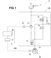
FIG. 1 is a fluid pressure circuit diagram of a brake fluid pressure control device for a vehicle, according to an embodiment of the present invention. -
FIG. 2A depicts a correlation diagram between time and speed. -
FIG. 2B depicts a correlation diagram between time and brake fluid pressure. -
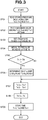
FIG. 3 is a control flowchart. -
FIG. 4A describes a modification to theFIG. 2A embodiment. -
FIG. 4B describes a modification to theFIG. 2B embodiment. - An embodiment of the present invention will be described below with reference to the accompanying drawings.
- As shown in
FIG. 1 , a brake fluidpressure control device 10 for a vehicle is configured to appropriately control a braking force (brake fluid pressure) applied onto wheels of the vehicle. In this embodiment, described is an example in which the brake fluid pressure control device is mounted on a bar handle vehicle, and applied on a front wheel of, for example, a two-wheel vehicle. - The brake fluid pressure control device for a
vehicle 10 includes, as its major elements, afluid pressure unit 100, which has fluid passages (brake fluid passages) and various parts, and acontrol device 200 to control various parts in thefluid pressure unit 100. Thefluid pressure unit 100 is arranged between amaster cylinder 12, which serves as a fluid pressure source, and awheel brake 14. - The
fluid pressure unit 100 includes an inlet control valve 15 (control valve means 15), which is a normally open solenoid valve disposed on a fluid pressure passage from themaster cylinder 12 to thewheel brake 14, an outlet control valve 16 (control valve means 16), which is a normally closed solenoid valve disposed on the fluid pressure passage from themaster cylinder 12 to thewheel brake 14, areservoir 13 to temporarily reserve the working fluid, acheck valve 18 arranged in parallel to theinlet control valve 15 to only admit the flow of the fluid toward themaster cylinder 12, apump part 21 to discharge the working fluid from thereservoir 13 toward themaster cylinder 12, and an actuator (motor) 22 to drive (actuate) thepump part 21. Thecontrol device 200 includes acontrol device 30 configured to control the actuation of theactuator 22, and control opening and closing of theinlet control valve 15 and theoutlet control valve 16. Thecontrol device 200 also includes adetermination device 31 configured to determine whether the road surface on which the vehicle is traveling has changed from a road surface with a low frictional coefficient to a road surface with a high frictional coefficient (whether the µ jump has taken placed). - A
wheel speed sensor 25 configured to detect the wheel speed of thewheel 23 is connected to thecontrol device 200. The wheel speed is obtained by thedetermination device 31, and the estimated vehicle body speed is calculated on the basis of the wheel speed. A signal that represents the µ jump determination, which is prepared by thedetermination device 31, a signal that represents the wheel speed, and a signal that represents the estimated vehicle body speed are transmitted to thecontrol device 30, and thecontrol device 30 performs ABS control and other processing, depending upon the result of the µ jump determination. Therefore, it is possible to improve qualities of the control such as the ABS control. - Firstly, fundamental operations during normal braking and the ABS control will be described. The brake fluid pressure control device for a
vehicle 10 has a function to switch between a normal state during the normal braking and states (reduced-pressure state, a holding state, and an increased-pressure state) during the ABS control. - During the normal braking: in the normal state (i.e., when no current is fed to the
inlet control valve 15 and the outlet control valve 16), themaster cylinder 12 communicates with the wheel brake 14 (theinlet control valve 15 is open), and thewheel brake 14 is disconnected from the reservoir 13 (theoutlet control valve 16 is closed). As an operation part (activating part) 11 is manipulated, the working fluid pressure is applied to thewheel brake 14 from themaster cylinder 12 through theinlet control valve 15 to brake the wheel. - During the ABS control; when the vehicle's wheel is about to lock, the
control device 200 switches among the reduced-pressure state, the holding state and the increased-pressure state so as to perform the ABS control. - In the reduced-pressure state of the ABS control, the current flows to the
inlet control valve 15 and theoutlet control valve 16 such that themaster cylinder 12 is disconnected from the wheel brake 14 (theinlet control valve 15 is closed), and thewheel brake 14 communicates with the reservoir 13 (theoutlet control valve 16 is open). The working fluid flowing to thewheel brake 14 is released to thereservoir 13 through theoutlet control valve 16, and therefore the working fluid pressure acting on thewheel brake 14 is reduced. - In the holding state of the ABS control, the current flows to the
inlet control valve 15 only, themaster cylinder 12 is disconnected from thewheel brake 14, and thewheel brake 14 is disconnected from the reservoir 13 (theinlet control valve 15 and theoutlet control valve 16 are closed). The working fluid is confined in the fluid passage closed by thewheel brake 14, theinlet control valve 15 and theoutlet control valve 16, and the working fluid pressure acting on the wheel brake is maintained at a constant value. - In the increased-pressure state of the ABS control, the feeding of the current to the
inlet control valve 15 and theoutlet control valve 16 is halted, themaster cylinder 12 communicates with the wheel brake 14 (theinlet control valve 15 is open), and thewheel brake 14 is disconnected from the reservoir 13 (theoutlet control valve 16 is closed). - As a result, the fluid pressure of the
wheel brake 14 is increased by the working fluid pressure from themaster cylinder 12. During the ABS control, thecontrol device 200 activates theactuator 22 so that thepump 21 is activated. Accordingly, the working fluid, which is temporarily reserved in thereservoir 13, is caused to return toward themaster cylinder 12. - In this manner, the brake fluid pressure control device for a
vehicle 10 can perform the fluid pressure control on the brake fluid pressure that acts on thewheel brake 14 by repeating the pressure increasing control, including the control on the reduced-pressure state, the holding state and the increased-pressure state. - Now, a determination device for determining whether the road surface on which the vehicle is traveling has changed from a road surface with a low frictional coefficient (may be referred to as a low µ road) to a road surface with a high frictional coefficient (may be referred to as a high µ road) (whether the µ jump has taken placed) will be described.
-
FIG. 2A shows a correlation diagram between the time and the speed during the ABS control. The solid line indicates the wheel speed, and the imaginary line indicates the estimated speed of the vehicle. Tn represents the pressure increasing time of the pressure increasing control in the current control cycle (current pressure increasing control), Tn-1 represents the pressure increasing time of the pressure increasing control in a control cycle of one-cycle-before the current control cycle, Tn-2 represents the pressure increasing time of the pressure increasing control in a control cycle of two-cycles-before the current control cycle, and Tn-3 represents the pressure increasing time of the pressure increasing control in a control cycle of three-cycles-before the current control cycle. - During the ABS control, the wheel speed gradually decreases as a whole, and the estimated speed of the vehicle also gradually decreases by repeating the control cycle including the increased-pressure state, the holding state and the reduced-pressure state of the brake fluid pressure.
- In
FIGS. 2A and 2B , the road surface on which the vehicle is travelling is a low µ road up to the time t13. At the time t13, the road surface on which the vehicle is travelling changes to a high µ road from the low µ road. -
FIG. 2A shows the wheel speed, andFIG. 2B shows the brake fluid pressure. The brake fluid pressure P1 is pressure at which the wheel tends to lock when the traveling road surface is the low µ road (this pressure may be referred to as low-µ-road lock-equivalent fluid pressure), and the brake fluid pressure P2 is pressure at which the wheel tends to lock when the traveling road surface is the high µ road (this pressure may be referred to as high-µ-road lock-equivalent pressure). - During the ABS control, if the traveling road surface is the low µ road, the brake fluid pressure is lowered by the pressure reducing control upon the brake fluid pressure reaching the low-µ-road lock-equivalent fluid pressure (time t1, t4, t7, t10). After the pressure reducing control, the brake fluid pressure is maintained at a constant value by the holding control (time t2, t5, t8, t11). Subsequently, the brake fluid pressure is raised by the pressure increasing control (time t3, t6, t9, t12). Such cycle of control is repeated.
- In
FIGS. 2A and 2B , the traveling road surface is a low µ road up to a certain point in time (time t13) in the current control cycle Cn. After that point in the current control cycle Cn, the road surface on which the vehicle is travelling changes to a high µ road. When the traveling road surface is the high µ road, the brake fluid pressure is increased until the brake fluid pressure reaches the-high-µ-road lock-equivalent fluid pressure P2, which is greater than low-µ-road lock-equivalent fluid pressure P1. Therefore, although the pressure increasing time Tn-3, Tn-2 and Tn-1 in those control cycles which are prior to the current control cycle does not change significantly, the pressure increasing time Tn becomes significantly long (large) in the current control cycle Cn, as compared to the pressure increasing time Tn-3, Tn-2 and Tn-1 in the immediately preceding pressure increasing control. Thus, when the pressure increasing time Tn is greater than the time Tth1 (Tn > Tth1) (time t14), it is determined that the µ jump has occurred. - A flowchart for determining whether the travelling road surface has changed to the high µ road from the low µ road for use with the above-described brake fluid pressure control device for a vehicle will be described below.
- As illustrated in
FIG. 3 , during the ABS control, thedetermination device 31 reads the stored pressure increasing time Tn-3, Tn-2 and Tn-1 in the three immediately preceding pressure increasing control at Step 01 (Step is abbreviated to ST hereinafter). - At ST02, the maximum value among the pressure increasing time Tn-3, Tn-2 and Tn-1 is taken as Tmax.
- At ST03, a predetermined offset value α is added to the maximum value Tmax, and the determination time Tth1 is set (Tht1 = Tmax + α). Then, the determination time Tth1 is taken as a threshold value.
- At ST04, the pressure increasing time Tn in the current pressure increasing control is measured.
- At ST05, it is determined whether the pressure increasing time Tn of the current pressure increasing control exceeds the determination time Tth1. If the pressure increasing time Tn exceeds the determination time Tth1 (ST05: YES), the processing goes to ST06; otherwise (ST05: NO), the processing goes to ST07.
- At ST06, generated is a signal that presents a fact that the frictional coefficient of the traveling road surface to the tire has changed to the high frictional coefficient (high µ) from the low frictional coefficient (low µ) (i.e., the µ jump has occurred). Then, the processing goes to ST07.
- After ST06 or when it is determined at ST05 that Tn is equal to or smaller than Tth1 (Tn ≤ Tth1), then at ST07 the pressure increasing time Tn-2 of the pressure increasing control of two-cycles-before the current pressure increasing control is rewritten to Tn-3, and the pressure increasing time Tn-1 of the pressure increasing control of one-cycle-before the current pressure increasing control is rewritten to Tn-2.
- At ST08, the value of time Tn-1 is rewritten to the pressure increasing time Tn of the current pressure increasing control.
- At ST09, the pressure increasing time Tn-3, Tn-2 and Tn-1 obtained upon rewriting is stored, and the processing ends.
- As described above, it is determined during the fluid pressure control whether the pressuring increasing time Tn of the current pressure increasing control exceeds the determination time Tth1 (Tmax +α), which is set on the basis of the pressure increasing time Tn-3, Tn-2 and Tn-1 of the past pressure increasing control. If the pressuring increasing time Tn of the current pressure increasing control exceeds the determination time Tth1 (Tmax +α), the control device makes a determination that the road surface on which the vehicle is travelling has changed to the road surface with the high frictional coefficient from the road surface with the low frictional coefficient.
- In this manner, it is possible to determine from the current and past pressure increasing time whether the road surface on which the vehicle is travelling has changed to the road surface with the high frictional coefficient from the road surface with the low frictional coefficient. Therefore, unlike the prior art, it is not necessary to estimate the deceleration of the vehicle body, and it is possible accurately determine, with a simple method, whether the road surface on which the vehicle is travelling has changed the road surface with the high frictional coefficient from the road surface with the low frictional coefficient (whether the µ jump has occurred).
- Furthermore, because the pressure increasing rate is raised to determine the occurrence of the µ jump at a stage prior to reaching the determination time, the lock-equivalent-fluid-pressure becomes considerably high if the µ jump has actually occurred (the change from the road surface with the low frictional coefficient to the road surface with the high frictional coefficient has actually occurred). Thus, even if the pressure increasing rate is raised, the current pressure increasing control continues for a while. As a result, the pressure increasing time of the current pressure increasing control exceeds the determination time, and it is determined that the µ jump has occurred. On the other hand, if the µ jump has not actually occurred, the brake fluid pressure will quickly reach the lock-equivalent-fluid-pressure upon raising the pressure increasing rate. Thus, the pressure increasing time of the current pressure increasing control does not exceed the determination time, and the determination of the occurrence of the µ jump is not made. For example, in a situation that the pressure increasing time becomes longer for some reasons although the µ jump has not actually occurred, it is possible to avoid erroneous determination by intentionally raising the pressure increasing rate as described above, and further improve the accuracy of the µ jump determination.
- It should be noted that although the determination time is set on the basis of the three pressure increasing time of the pressure increasing control in the three immediately preceding control cycles in the embodiment, the present invention is not limited to this. The determination time may be set on the basis of arbitrary pressure increasing time of the past pressure increasing control, e.g., the single or two pressure increasing time in the single or two immediately preceding control cycle, the five or more pressure increasing time in the five or more immediately preceding control cycles, or the three pressure increasing time in the three control cycles immediately prior to the immediately preceding control cycle.
- It should also be noted that although the determination time is decided by adding the predetermined offset to the maximum value of the pressure increasing time among a predetermined number of pressure increasing control immediately prior to the current pressure increasing control in the embodiment, the present invention is not limited to this. For example, the determination time may be decided by adding a predetermined offset value to an average value of the pressure increasing time in a predetermined number of past pressure increasing control. It should also be noted that although the determination time may be decided by adding the offset value to the above-mentioned maximum value, the above-mentioned average value or a value of arbitrary pressure increasing control, the present invention is not limited to them. For example, the determination time may be decided by multiplying the above-mentioned maximum value, the above-mentioned average value or the value of arbitrary pressure increasing control by a predetermined coefficient such as 1.1 or 1.2.
- Now, a modification to the determination device will be described.
-
FIGS. 4A and 4B are views useful to describe a modification to the embodiment ofFIGS. 2A and 2B . The modification is different from the above-described embodiment in that the pressure increasing rate is raised when the prescribed time Tth2, which is shorter than the determination time Tth1, is reached in the current control cycle. - During the ABS control, if the traveling road surface is a low µ road, the brake fluid pressure is reduced by the pressure reducing control upon the brake fluid pressure reaching the low-µ-road lock-equivalent-liquid-pressure (time t21, t24, t27, t30). After the pressure reducing control, the brake fluid pressure is maintained at a constant value by the holding control (t22, t25, t28, t31). Subsequently, the brake fluid pressure is increased by the pressure increasing control (time t23, t26, t29, t32). Such cycle of control is repeated.
- In
FIGS. 4A and 4B , the traveling road surface is the low µ road up to a certain point in time (time t33) in the current control cycle Cn. After that point in the current control cycle Cn, the road surface on which the vehicle is travelling changes to the high µ road. When the travelling road surface is the high µ road, the fluid pressure is increased until the fluid pressure reaches the high-µ-road lock-equivalent-liquid-pressure P2, which is greater than the low-µ-road lock-equivalent-liquid-pressure P1. Therefore, although the pressure increasing time Tn-3, Tn-2 and Tn-1 do not change significantly in those control cycles which are prior to the current control cycle, the pressure increasing time Tn considerably becomes longer (larger) in the current control cycle Cn, as compared to the pressure increasing time Tn-3, Tn-2 and Tn-1 in the immediately preceding pressure increasing control. Thus, when the pressure increasing time Tn is greater than the time Tth1 (Tn > Tth1) (time t35), it is determined that the µ jump has occurred. - Because the pressure increasing rate is raised to determine the occurrence of the µ jump at a stage prior to reaching the determination time, the lock-equivalent-fluid-pressure becomes considerably high if the µ jump has actually occurred (the change from the road surface with the low frictional coefficient to the road surface with the high frictional coefficient has actually occurred). Thus, even if the pressure increasing rate is raised, the current pressure increasing control continues for a while. As a result, the pressure increasing time of the current pressure increasing control exceeds the determination time, and it is determined that the µ jump has occurred. On the other hand, if the µ jump has not actually occurred, the brake fluid pressure will quickly reach the lock-equivalent-fluid-pressure upon raising the pressure increasing rate. Thus, the pressure increasing time of the current pressure increasing control does not exceed the determination time, and the determination of the occurrence of the µ jump is not made. For example, in a situation that the pressure increasing time becomes longer for some reasons although the µ jump has not actually occurred, it is possible to avoid erroneous determination by intentionally raising the pressure increasing rate as described above, and further improve the accuracy of the µ jump determination.
- It should be noted that although the embodiment has described an example in which the wheel brake fluid pressure control device is disposed only on the front wheel, the wheel brake fluid pressure control device may be disposed only on the rear wheel or both of the wheels.
- The present invention is advantageously applied to the brake fluid pressure control device mounted on the motorcycle.
-
- 10: Brake fluid pressure control device for a vehicle
- 14: Wheel brake
- 21: Pump (solenoid pump)
- 30: Control device
- 31: Determination device
- Tn: Pressure increasing time in the current pressure increasing control
- Tn-1, Tn-2, Tn-3: Pressure increasing time in the past pressure increasing control
- Tth1 (Tmax + α): Determination time
Claims (4)
- A brake fluid pressure control device for a vehicle, configured to be able to perform fluid pressure control for controlling brake fluid pressure acting on a wheel brake by repeating a control cycle including, at least, pressure increasing control and pressure reducing control,
the brake fluid pressure control device configured to determine whether pressure increasing time of current pressure increasing control exceeds determination time, which is set based on pressure increasing time of past pressure increasing control, during the fluid pressure control, and
the brake fluid pressure control device configured to make a determination that a road surface on which the vehicle is travelling has changed to a road surface with a high frictional coefficient from a road surface with a low frictional coefficient if the pressure increasing time of the current pressure increasing control exceeds the determination time. - The brake fluid pressure control device for a vehicle according to claim 1, wherein a pressure increasing rate is altered to a higher value in the current pressure increasing control when the pressure increasing time of the current pressure increasing control reaches prescribed time that is shorter than the determination time.
- The brake fluid pressure control device for a vehicle according to claim 1 or claim 2, wherein the determination time is set based on the pressure increasing time of a predetermined number of past pressure increasing control immediately prior to the current pressure increasing control.
- The brake fluid pressure control device for a vehicle according to claim 3, wherein the determination time is set by adding a predetermined offset value to a maximum value of the pressure increasing time among a predetermined number of past pressure increasing control immediately prior to the current pressure increasing control.
Applications Claiming Priority (2)
| Application Number | Priority Date | Filing Date | Title |
|---|---|---|---|
| JP2016073548 | 2016-03-31 | ||
| PCT/JP2017/007926 WO2017169475A1 (en) | 2016-03-31 | 2017-02-28 | Vehicle brake hydraulic control device |
Publications (3)
| Publication Number | Publication Date |
|---|---|
| EP3437944A1 true EP3437944A1 (en) | 2019-02-06 |
| EP3437944A4 EP3437944A4 (en) | 2019-10-23 |
| EP3437944B1 EP3437944B1 (en) | 2020-11-11 |
Family
ID=59964017
Family Applications (1)
| Application Number | Title | Priority Date | Filing Date |
|---|---|---|---|
| EP17774020.6A Active EP3437944B1 (en) | 2016-03-31 | 2017-02-28 | Vehicle brake hydraulic control device |
Country Status (7)
| Country | Link |
|---|---|
| US (1) | US10737670B2 (en) |
| EP (1) | EP3437944B1 (en) |
| JP (1) | JP6611912B2 (en) |
| AU (1) | AU2017242180B2 (en) |
| CA (1) | CA3016425C (en) |
| ES (1) | ES2850598T3 (en) |
| WO (1) | WO2017169475A1 (en) |
Families Citing this family (1)
| Publication number | Priority date | Publication date | Assignee | Title |
|---|---|---|---|---|
| JP2021030782A (en) * | 2019-08-20 | 2021-03-01 | ロベルト・ボッシュ・ゲゼルシャフト・ミト・ベシュレンクテル・ハフツングRobert Bosch Gmbh | Control device and control method |
Family Cites Families (10)
| Publication number | Priority date | Publication date | Assignee | Title |
|---|---|---|---|---|
| US4881784A (en) * | 1989-02-03 | 1989-11-21 | General Motors Corporation | ABS pressure apply algorithm |
| JP2682125B2 (en) * | 1989-04-05 | 1997-11-26 | トヨタ自動車株式会社 | Anti-skid control device |
| JPH04356261A (en) * | 1991-05-31 | 1992-12-09 | Jidosha Kiki Co Ltd | Method for judging coefficient of friction of road surface and method for controlling anti-skid brake using this judging method |
| JP3215463B2 (en) | 1991-10-14 | 2001-10-09 | 本田技研工業株式会社 | Brake control method |
| JP3735903B2 (en) * | 1995-09-19 | 2006-01-18 | アイシン精機株式会社 | Anti-skid control device for electric vehicle |
| DE19849773A1 (en) * | 1997-10-29 | 1999-06-17 | Aisin Seiki | Antiskid controller used in motor vehicle |
| JPH11129883A (en) * | 1997-10-29 | 1999-05-18 | Aisin Seiki Co Ltd | Anti-skid control device |
| JP2003048526A (en) * | 2001-08-02 | 2003-02-18 | Hitachi Unisia Automotive Ltd | Anti-skid control device for four-wheel drive vehicle |
| JP5123917B2 (en) * | 2009-10-19 | 2013-01-23 | 日信工業株式会社 | Brake hydraulic pressure control device for vehicles |
| JP5884239B2 (en) | 2012-03-30 | 2016-03-15 | オートリブ日信ブレーキシステムジャパン株式会社 | Brake hydraulic pressure control device for vehicles |
-
2017
- 2017-02-28 EP EP17774020.6A patent/EP3437944B1/en active Active
- 2017-02-28 ES ES17774020T patent/ES2850598T3/en active Active
- 2017-02-28 US US16/082,827 patent/US10737670B2/en active Active
- 2017-02-28 AU AU2017242180A patent/AU2017242180B2/en active Active
- 2017-02-28 CA CA3016425A patent/CA3016425C/en active Active
- 2017-02-28 JP JP2018508829A patent/JP6611912B2/en active Active
- 2017-02-28 WO PCT/JP2017/007926 patent/WO2017169475A1/en not_active Ceased
Also Published As
| Publication number | Publication date |
|---|---|
| WO2017169475A1 (en) | 2017-10-05 |
| CA3016425A1 (en) | 2017-10-05 |
| JP6611912B2 (en) | 2019-11-27 |
| ES2850598T3 (en) | 2021-08-30 |
| EP3437944B1 (en) | 2020-11-11 |
| CA3016425C (en) | 2020-09-22 |
| BR112018070077A2 (en) | 2019-02-12 |
| US10737670B2 (en) | 2020-08-11 |
| US20190092293A1 (en) | 2019-03-28 |
| JPWO2017169475A1 (en) | 2018-12-20 |
| EP3437944A4 (en) | 2019-10-23 |
| AU2017242180A1 (en) | 2018-09-13 |
| AU2017242180B2 (en) | 2019-08-22 |
| BR112018070077A8 (en) | 2022-07-05 |
Similar Documents
| Publication | Publication Date | Title |
|---|---|---|
| US8007054B2 (en) | Vehicle brake hydraulic pressure control apparatus | |
| US20100023237A1 (en) | Brake control device for two-wheeled motor vehicle | |
| US8417429B2 (en) | Vehicle brake fluid pressure control apparatus | |
| CA3016425C (en) | Vehicle brake hydraulic control device | |
| JP6393600B2 (en) | Brake control device for bar handle vehicle | |
| JP5884244B2 (en) | Brake hydraulic pressure control device for vehicles | |
| CA3018944C (en) | Brake fluid pressure control device for vehicle | |
| JP4897598B2 (en) | Brake hydraulic pressure control device for vehicles | |
| CA3017587C (en) | Brake fluid pressure control device for vehicle | |
| CN114222688B (en) | Control device and control method | |
| AU2017242181B2 (en) | Vehicle brake hydraulic control device | |
| BR112018070077B1 (en) | BRAKE FLUID PRESSURE CONTROL DEVICE FOR A VEHICLE |
Legal Events
| Date | Code | Title | Description |
|---|---|---|---|
| STAA | Information on the status of an ep patent application or granted ep patent |
Free format text: STATUS: THE INTERNATIONAL PUBLICATION HAS BEEN MADE |
|
| PUAI | Public reference made under article 153(3) epc to a published international application that has entered the european phase |
Free format text: ORIGINAL CODE: 0009012 |
|
| STAA | Information on the status of an ep patent application or granted ep patent |
Free format text: STATUS: REQUEST FOR EXAMINATION WAS MADE |
|
| 17P | Request for examination filed |
Effective date: 20180828 |
|
| AK | Designated contracting states |
Kind code of ref document: A1 Designated state(s): AL AT BE BG CH CY CZ DE DK EE ES FI FR GB GR HR HU IE IS IT LI LT LU LV MC MK MT NL NO PL PT RO RS SE SI SK SM TR |
|
| AX | Request for extension of the european patent |
Extension state: BA ME |
|
| DAV | Request for validation of the european patent (deleted) | ||
| DAX | Request for extension of the european patent (deleted) | ||
| A4 | Supplementary search report drawn up and despatched |
Effective date: 20190923 |
|
| RIC1 | Information provided on ipc code assigned before grant |
Ipc: B60T 8/1764 20060101ALI20190917BHEP Ipc: B60T 8/172 20060101AFI20190917BHEP Ipc: B60T 8/1763 20060101ALI20190917BHEP Ipc: B60T 8/1761 20060101ALI20190917BHEP |
|
| GRAP | Despatch of communication of intention to grant a patent |
Free format text: ORIGINAL CODE: EPIDOSNIGR1 |
|
| STAA | Information on the status of an ep patent application or granted ep patent |
Free format text: STATUS: GRANT OF PATENT IS INTENDED |
|
| INTG | Intention to grant announced |
Effective date: 20200623 |
|
| GRAS | Grant fee paid |
Free format text: ORIGINAL CODE: EPIDOSNIGR3 |
|
| GRAA | (expected) grant |
Free format text: ORIGINAL CODE: 0009210 |
|
| STAA | Information on the status of an ep patent application or granted ep patent |
Free format text: STATUS: THE PATENT HAS BEEN GRANTED |
|
| AK | Designated contracting states |
Kind code of ref document: B1 Designated state(s): AL AT BE BG CH CY CZ DE DK EE ES FI FR GB GR HR HU IE IS IT LI LT LU LV MC MK MT NL NO PL PT RO RS SE SI SK SM TR |
|
| REG | Reference to a national code |
Ref country code: GB Ref legal event code: FG4D |
|
| REG | Reference to a national code |
Ref country code: CH Ref legal event code: EP |
|
| REG | Reference to a national code |
Ref country code: AT Ref legal event code: REF Ref document number: 1333175 Country of ref document: AT Kind code of ref document: T Effective date: 20201115 |
|
| REG | Reference to a national code |
Ref country code: DE Ref legal event code: R096 Ref document number: 602017027446 Country of ref document: DE |
|
| REG | Reference to a national code |
Ref country code: IE Ref legal event code: FG4D |
|
| REG | Reference to a national code |
Ref country code: NL Ref legal event code: MP Effective date: 20201111 |
|
| REG | Reference to a national code |
Ref country code: AT Ref legal event code: MK05 Ref document number: 1333175 Country of ref document: AT Kind code of ref document: T Effective date: 20201111 |
|
| PG25 | Lapsed in a contracting state [announced via postgrant information from national office to epo] |
Ref country code: FI Free format text: LAPSE BECAUSE OF FAILURE TO SUBMIT A TRANSLATION OF THE DESCRIPTION OR TO PAY THE FEE WITHIN THE PRESCRIBED TIME-LIMIT Effective date: 20201111 Ref country code: RS Free format text: LAPSE BECAUSE OF FAILURE TO SUBMIT A TRANSLATION OF THE DESCRIPTION OR TO PAY THE FEE WITHIN THE PRESCRIBED TIME-LIMIT Effective date: 20201111 Ref country code: PT Free format text: LAPSE BECAUSE OF FAILURE TO SUBMIT A TRANSLATION OF THE DESCRIPTION OR TO PAY THE FEE WITHIN THE PRESCRIBED TIME-LIMIT Effective date: 20210311 Ref country code: NO Free format text: LAPSE BECAUSE OF FAILURE TO SUBMIT A TRANSLATION OF THE DESCRIPTION OR TO PAY THE FEE WITHIN THE PRESCRIBED TIME-LIMIT Effective date: 20210211 Ref country code: GR Free format text: LAPSE BECAUSE OF FAILURE TO SUBMIT A TRANSLATION OF THE DESCRIPTION OR TO PAY THE FEE WITHIN THE PRESCRIBED TIME-LIMIT Effective date: 20210212 |
|
| PG25 | Lapsed in a contracting state [announced via postgrant information from national office to epo] |
Ref country code: AT Free format text: LAPSE BECAUSE OF FAILURE TO SUBMIT A TRANSLATION OF THE DESCRIPTION OR TO PAY THE FEE WITHIN THE PRESCRIBED TIME-LIMIT Effective date: 20201111 Ref country code: BG Free format text: LAPSE BECAUSE OF FAILURE TO SUBMIT A TRANSLATION OF THE DESCRIPTION OR TO PAY THE FEE WITHIN THE PRESCRIBED TIME-LIMIT Effective date: 20210211 Ref country code: LV Free format text: LAPSE BECAUSE OF FAILURE TO SUBMIT A TRANSLATION OF THE DESCRIPTION OR TO PAY THE FEE WITHIN THE PRESCRIBED TIME-LIMIT Effective date: 20201111 Ref country code: PL Free format text: LAPSE BECAUSE OF FAILURE TO SUBMIT A TRANSLATION OF THE DESCRIPTION OR TO PAY THE FEE WITHIN THE PRESCRIBED TIME-LIMIT Effective date: 20201111 Ref country code: IS Free format text: LAPSE BECAUSE OF FAILURE TO SUBMIT A TRANSLATION OF THE DESCRIPTION OR TO PAY THE FEE WITHIN THE PRESCRIBED TIME-LIMIT Effective date: 20210311 Ref country code: SE Free format text: LAPSE BECAUSE OF FAILURE TO SUBMIT A TRANSLATION OF THE DESCRIPTION OR TO PAY THE FEE WITHIN THE PRESCRIBED TIME-LIMIT Effective date: 20201111 |
|
| REG | Reference to a national code |
Ref country code: LT Ref legal event code: MG9D |
|
| PG25 | Lapsed in a contracting state [announced via postgrant information from national office to epo] |
Ref country code: HR Free format text: LAPSE BECAUSE OF FAILURE TO SUBMIT A TRANSLATION OF THE DESCRIPTION OR TO PAY THE FEE WITHIN THE PRESCRIBED TIME-LIMIT Effective date: 20201111 |
|
| PG25 | Lapsed in a contracting state [announced via postgrant information from national office to epo] |
Ref country code: SK Free format text: LAPSE BECAUSE OF FAILURE TO SUBMIT A TRANSLATION OF THE DESCRIPTION OR TO PAY THE FEE WITHIN THE PRESCRIBED TIME-LIMIT Effective date: 20201111 Ref country code: RO Free format text: LAPSE BECAUSE OF FAILURE TO SUBMIT A TRANSLATION OF THE DESCRIPTION OR TO PAY THE FEE WITHIN THE PRESCRIBED TIME-LIMIT Effective date: 20201111 Ref country code: SM Free format text: LAPSE BECAUSE OF FAILURE TO SUBMIT A TRANSLATION OF THE DESCRIPTION OR TO PAY THE FEE WITHIN THE PRESCRIBED TIME-LIMIT Effective date: 20201111 Ref country code: LT Free format text: LAPSE BECAUSE OF FAILURE TO SUBMIT A TRANSLATION OF THE DESCRIPTION OR TO PAY THE FEE WITHIN THE PRESCRIBED TIME-LIMIT Effective date: 20201111 Ref country code: EE Free format text: LAPSE BECAUSE OF FAILURE TO SUBMIT A TRANSLATION OF THE DESCRIPTION OR TO PAY THE FEE WITHIN THE PRESCRIBED TIME-LIMIT Effective date: 20201111 Ref country code: CZ Free format text: LAPSE BECAUSE OF FAILURE TO SUBMIT A TRANSLATION OF THE DESCRIPTION OR TO PAY THE FEE WITHIN THE PRESCRIBED TIME-LIMIT Effective date: 20201111 |
|
| REG | Reference to a national code |
Ref country code: DE Ref legal event code: R097 Ref document number: 602017027446 Country of ref document: DE |
|
| REG | Reference to a national code |
Ref country code: ES Ref legal event code: FG2A Ref document number: 2850598 Country of ref document: ES Kind code of ref document: T3 Effective date: 20210830 |
|
| PG25 | Lapsed in a contracting state [announced via postgrant information from national office to epo] |
Ref country code: DK Free format text: LAPSE BECAUSE OF FAILURE TO SUBMIT A TRANSLATION OF THE DESCRIPTION OR TO PAY THE FEE WITHIN THE PRESCRIBED TIME-LIMIT Effective date: 20201111 |
|
| PLBE | No opposition filed within time limit |
Free format text: ORIGINAL CODE: 0009261 |
|
| STAA | Information on the status of an ep patent application or granted ep patent |
Free format text: STATUS: NO OPPOSITION FILED WITHIN TIME LIMIT |
|
| PG25 | Lapsed in a contracting state [announced via postgrant information from national office to epo] |
Ref country code: MC Free format text: LAPSE BECAUSE OF FAILURE TO SUBMIT A TRANSLATION OF THE DESCRIPTION OR TO PAY THE FEE WITHIN THE PRESCRIBED TIME-LIMIT Effective date: 20201111 |
|
| 26N | No opposition filed |
Effective date: 20210812 |
|
| REG | Reference to a national code |
Ref country code: BE Ref legal event code: MM Effective date: 20210228 |
|
| PG25 | Lapsed in a contracting state [announced via postgrant information from national office to epo] |
Ref country code: NL Free format text: LAPSE BECAUSE OF FAILURE TO SUBMIT A TRANSLATION OF THE DESCRIPTION OR TO PAY THE FEE WITHIN THE PRESCRIBED TIME-LIMIT Effective date: 20201111 Ref country code: CH Free format text: LAPSE BECAUSE OF NON-PAYMENT OF DUE FEES Effective date: 20210228 Ref country code: AL Free format text: LAPSE BECAUSE OF FAILURE TO SUBMIT A TRANSLATION OF THE DESCRIPTION OR TO PAY THE FEE WITHIN THE PRESCRIBED TIME-LIMIT Effective date: 20201111 Ref country code: LU Free format text: LAPSE BECAUSE OF NON-PAYMENT OF DUE FEES Effective date: 20210228 Ref country code: LI Free format text: LAPSE BECAUSE OF NON-PAYMENT OF DUE FEES Effective date: 20210228 |
|
| REG | Reference to a national code |
Ref country code: DE Ref legal event code: R081 Ref document number: 602017027446 Country of ref document: DE Owner name: HITACHI ASTEMO, LTD., HITACHINAKA-SHI, JP Free format text: FORMER OWNER: NISSIN KOGYO CO., LTD., TOMI-CITY, NAGANO, JP |
|
| PG25 | Lapsed in a contracting state [announced via postgrant information from national office to epo] |
Ref country code: SI Free format text: LAPSE BECAUSE OF FAILURE TO SUBMIT A TRANSLATION OF THE DESCRIPTION OR TO PAY THE FEE WITHIN THE PRESCRIBED TIME-LIMIT Effective date: 20201111 |
|
| REG | Reference to a national code |
Ref country code: GB Ref legal event code: 732E Free format text: REGISTERED BETWEEN 20211210 AND 20211215 |
|
| PG25 | Lapsed in a contracting state [announced via postgrant information from national office to epo] |
Ref country code: IE Free format text: LAPSE BECAUSE OF NON-PAYMENT OF DUE FEES Effective date: 20210228 |
|
| REG | Reference to a national code |
Ref country code: ES Ref legal event code: PC2A Owner name: HITACHI ASTEMO, LTD. Effective date: 20220512 |
|
| PG25 | Lapsed in a contracting state [announced via postgrant information from national office to epo] |
Ref country code: IS Free format text: LAPSE BECAUSE OF FAILURE TO SUBMIT A TRANSLATION OF THE DESCRIPTION OR TO PAY THE FEE WITHIN THE PRESCRIBED TIME-LIMIT Effective date: 20210311 |
|
| PG25 | Lapsed in a contracting state [announced via postgrant information from national office to epo] |
Ref country code: BE Free format text: LAPSE BECAUSE OF NON-PAYMENT OF DUE FEES Effective date: 20210228 |
|
| PG25 | Lapsed in a contracting state [announced via postgrant information from national office to epo] |
Ref country code: CY Free format text: LAPSE BECAUSE OF FAILURE TO SUBMIT A TRANSLATION OF THE DESCRIPTION OR TO PAY THE FEE WITHIN THE PRESCRIBED TIME-LIMIT Effective date: 20201111 |
|
| PG25 | Lapsed in a contracting state [announced via postgrant information from national office to epo] |
Ref country code: HU Free format text: LAPSE BECAUSE OF FAILURE TO SUBMIT A TRANSLATION OF THE DESCRIPTION OR TO PAY THE FEE WITHIN THE PRESCRIBED TIME-LIMIT; INVALID AB INITIO Effective date: 20170228 |
|
| PG25 | Lapsed in a contracting state [announced via postgrant information from national office to epo] |
Ref country code: MK Free format text: LAPSE BECAUSE OF FAILURE TO SUBMIT A TRANSLATION OF THE DESCRIPTION OR TO PAY THE FEE WITHIN THE PRESCRIBED TIME-LIMIT Effective date: 20201111 |
|
| PG25 | Lapsed in a contracting state [announced via postgrant information from national office to epo] |
Ref country code: MT Free format text: LAPSE BECAUSE OF FAILURE TO SUBMIT A TRANSLATION OF THE DESCRIPTION OR TO PAY THE FEE WITHIN THE PRESCRIBED TIME-LIMIT Effective date: 20201111 |
|
| PG25 | Lapsed in a contracting state [announced via postgrant information from national office to epo] |
Ref country code: TR Free format text: LAPSE BECAUSE OF FAILURE TO SUBMIT A TRANSLATION OF THE DESCRIPTION OR TO PAY THE FEE WITHIN THE PRESCRIBED TIME-LIMIT Effective date: 20201111 |
|
| PGFP | Annual fee paid to national office [announced via postgrant information from national office to epo] |
Ref country code: FR Payment date: 20251231 Year of fee payment: 10 |
|
| PGFP | Annual fee paid to national office [announced via postgrant information from national office to epo] |
Ref country code: GB Payment date: 20260106 Year of fee payment: 10 |
|
| PGFP | Annual fee paid to national office [announced via postgrant information from national office to epo] |
Ref country code: ES Payment date: 20260304 Year of fee payment: 10 |
|
| PGFP | Annual fee paid to national office [announced via postgrant information from national office to epo] |
Ref country code: DE Payment date: 20260102 Year of fee payment: 10 |
|
| PGFP | Annual fee paid to national office [announced via postgrant information from national office to epo] |
Ref country code: IT Payment date: 20260122 Year of fee payment: 10 |