EP3437845A1 - Method for making polarized and photochromic thermoplastic lenses - Google Patents
Method for making polarized and photochromic thermoplastic lenses Download PDFInfo
- Publication number
- EP3437845A1 EP3437845A1 EP17306036.9A EP17306036A EP3437845A1 EP 3437845 A1 EP3437845 A1 EP 3437845A1 EP 17306036 A EP17306036 A EP 17306036A EP 3437845 A1 EP3437845 A1 EP 3437845A1
- Authority
- EP
- European Patent Office
- Prior art keywords
- layer
- adhesion
- optical article
- functional
- lens
- Prior art date
- Legal status (The legal status is an assumption and is not a legal conclusion. Google has not performed a legal analysis and makes no representation as to the accuracy of the status listed.)
- Withdrawn
Links
Images


Classifications
-
- B—PERFORMING OPERATIONS; TRANSPORTING
- B29—WORKING OF PLASTICS; WORKING OF SUBSTANCES IN A PLASTIC STATE IN GENERAL
- B29D—PRODUCING PARTICULAR ARTICLES FROM PLASTICS OR FROM SUBSTANCES IN A PLASTIC STATE
- B29D11/00—Producing optical elements, e.g. lenses or prisms
- B29D11/00009—Production of simple or compound lenses
- B29D11/00432—Auxiliary operations, e.g. machines for filling the moulds
-
- B—PERFORMING OPERATIONS; TRANSPORTING
- B29—WORKING OF PLASTICS; WORKING OF SUBSTANCES IN A PLASTIC STATE IN GENERAL
- B29C—SHAPING OR JOINING OF PLASTICS; SHAPING OF MATERIAL IN A PLASTIC STATE, NOT OTHERWISE PROVIDED FOR; AFTER-TREATMENT OF THE SHAPED PRODUCTS, e.g. REPAIRING
- B29C45/00—Injection moulding, i.e. forcing the required volume of moulding material through a nozzle into a closed mould; Apparatus therefor
- B29C45/14—Injection moulding, i.e. forcing the required volume of moulding material through a nozzle into a closed mould; Apparatus therefor incorporating preformed parts or layers, e.g. injection moulding around inserts or for coating articles
- B29C45/14778—Injection moulding, i.e. forcing the required volume of moulding material through a nozzle into a closed mould; Apparatus therefor incorporating preformed parts or layers, e.g. injection moulding around inserts or for coating articles the article consisting of a material with particular properties, e.g. porous, brittle
- B29C45/14811—Multilayered articles
-
- B—PERFORMING OPERATIONS; TRANSPORTING
- B29—WORKING OF PLASTICS; WORKING OF SUBSTANCES IN A PLASTIC STATE IN GENERAL
- B29D—PRODUCING PARTICULAR ARTICLES FROM PLASTICS OR FROM SUBSTANCES IN A PLASTIC STATE
- B29D11/00—Producing optical elements, e.g. lenses or prisms
- B29D11/00634—Production of filters
- B29D11/00644—Production of filters polarizing
-
- B—PERFORMING OPERATIONS; TRANSPORTING
- B29—WORKING OF PLASTICS; WORKING OF SUBSTANCES IN A PLASTIC STATE IN GENERAL
- B29D—PRODUCING PARTICULAR ARTICLES FROM PLASTICS OR FROM SUBSTANCES IN A PLASTIC STATE
- B29D11/00—Producing optical elements, e.g. lenses or prisms
- B29D11/00634—Production of filters
- B29D11/00653—Production of filters photochromic
-
- B—PERFORMING OPERATIONS; TRANSPORTING
- B29—WORKING OF PLASTICS; WORKING OF SUBSTANCES IN A PLASTIC STATE IN GENERAL
- B29D—PRODUCING PARTICULAR ARTICLES FROM PLASTICS OR FROM SUBSTANCES IN A PLASTIC STATE
- B29D11/00—Producing optical elements, e.g. lenses or prisms
- B29D11/0073—Optical laminates
Definitions
- the present disclosure relates generally to methods for making optical articles having single or multi-layer functional wafer and thermoplastic lenses by using adhesion-promoting layers; such methods may include using injection molding methods to produce an optical article.
- Methods of making an optical element through injection molding include injecting a molten lens material against a functional wafer or by overmolding a functional wafer onto a lens.
- the molten lens material cools to form a lens, and the lens, together with the functional wafer, form an optical article.
- it is required and important to have a clear, non-hazy, invisible interface and strong adhesion between the functional wafer and the lens.
- the material of the functional wafer needs to be the same or compatible with the material of the lens.
- the resulting optical article will have poor adhesion between the functional wafer and the lens material and/or the interface between the functional wafer and the lens material will be cloudy and non-clear, both of which are unsuitable for optical lens applications. Since not many clear lens materials are compatible (or miscible) to form an invisible interface and create a strong fuse-bonding with commercially available functional wafers, methods employed by the industry are forced to use functional wafers having the same material as the lens material when making optical elements by injection molding.
- the present disclosure addresses the need for an efficient and cost effective method of making an optical article using single or multi-functional wafers and a thermoplastic lens material.
- the inventors have found that using an adhesive-promoting layer enables the production of optical articles using widely available single or multi-functional wafers while at the same time ensuring not only an invisible interface but also a strong bond between the single or multi-functional wafer and the lens material, regardless of the materials of the functional wafer and lens.
- an optical article comprising a single or multi-layered functional wafer having: a first outer surface; a second outer surface opposite the first outer surface; and at least one light filtering functional layer disposed between the first outer surface and the second outer surface. At least one of the first outer surface and the second outer surface may be coated with an adhesion-promoting layer.
- the optical article comprises a lens comprised of a thermoplastic material, the lens being coupled to the optical article via the adhesion-promoting layer.
- the at least one light filtering functional layer may be a polarizing layer and/or a photochromic layer. The at least one light filtering functional layer may partially block visible light in the 400-500 nm wavelength range, visible light in the 500-700 nm wavelength range, and/or near-infrared light in the 700-1400 nm wavelength range.
- the at least one light filtering functional may be a multi-layer optical film (MOF) filter, for example, a 3M MOF filter.
- the at least one light filtering functional layer may be a holographic film, for example, a Covestro light filtering functional layer, in which the at least one light filtering functional layer is a spectral filtering layer and provides augmented reality display by reflecting light from a light source embedded in, for example, eye wear associated with the optical article.
- the lens may be coupled to the adhesion-promoting layer using injection molding techniques, and the lens may be a polyamide (PA), a thermoplastic polyurethane (TPU), a polycarbonate (PC), a polymethyl methacrylate (PMMA), a cyclic olefin copolymer (COC), and/or a cyclic olefin polymer (COP).
- PA polyamide
- TPU thermoplastic polyurethane
- PC polycarbonate
- PMMA polymethyl methacrylate
- COC cyclic olefin copolymer
- COP cyclic olefin polymer
- the adhesion-promoting layer may be a UV curable acrylic and/or a polyurethane modified ethoxylated bisphenol A diacrylate.
- the single or multi-layered functional wafer may comprise first and second protective layers, the first and second protective layers defining upper and lower surfaces of the single or multi-functional wafer.
- the upper and/or lower surface of the single or multi-layered functional wafer may be coated with an adhesion-promoting layer.
- the at least one light filtering functional layer may be a polyvinyl alcohol (PVA), polyurethane (PU), triacetate cellulose (TAC), or cellulose acetate butyrate (CAB), and the first and second protective layers are polycarbonate (PC) and/or the first and second protective layers are triacetate cellulose (TAC).
- the first and second protective layers may be polycarbonate (PC), and the adhesion-promoting layer may include a UV curable acrylic and may have a thickness in a range of essentially 1 ⁇ m to 10 ⁇ m
- the first and second protective layers may be polycarbonate (PC)
- the adhesion-promoting layer may include polyurethane modified ethoxylated bisphenol A diacrylate and may be coated onto the upper surface and the lower surface of the single or multi-layered functional wafer.
- a method for producing an optical article using injection molding comprises the steps of coating an adhesion-promoting layer onto a single or multi-layer functional wafer having: a first outer surface; a second outer surface opposite the first outer surface; and at least one light filtering functional layer disposed between the first outer surface and the second outer surface, where the adhesion-promoting layer coats the first outer surface and/or the second outer surface; inserting the single or multi-layer functional wafer into a mold cavity; and injecting a thermoplastic lens material bonding onto the adhesion-promoting layer to form an optical article, the optical article including: the single or multi-layer functional wafer; the adhesion-promoting layer; and a lens comprising the thermoplastic material.
- the at least one light filtering functional layer may be a polarizing layer and/or a photochromic layer. In some aspects, the at least one light filtering functional layer may partially block visible light in the 400-500 nm wavelength range, visible light in the 500-700 nm wavelength range, and/or near-infrared light in the 700-1400 nm wavelength range.
- the thermoplastic lens material may be a polyamide (PA), a thermoplastic polyurethane (TPU), a polycarbonate (PC), a polymethyl methacrylate (PMMA), a cyclic olefin copolymer (COC), and/or (vi) cyclic olefin polymer (COP).
- the adhesion promoting layer may be a UV curable acrylic, and/or a polyurethane modified ethoxylated bisphenol A diacrylate.
- the single or multi-layer functional wafer may comprise: first and second protective layers with the at least one light filtering functional layer disposed between them, the at least one light filtering functional layer being a (i) polyvinyl alcohol (PVA), (ii) polyurethane (PU), (iii) triacetate cellulose (TAC), or (iv) cellulose acetate butyrate (CAB).
- the first and second protective layers are polycarbonate (PC), and/or the first and second protective layers are triacetate cellulose (TAC).
- optical article is defined as a transparent or translucent object through which a person on one side of the optical article may visually perceive an object on the opposite side.
- optical articles include sunglasses, fashion lenses, non-prescription and prescription lenses, sport masks, and goggles.
- compositions and/or methods can consist of or consist essentially of-rather than comprise/include/contain/have-any of the described elements and/or features and/or steps.
- the term “consisting of” or “consisting essentially of” can be substituted for any of the open-ended linking verbs recited above, in order to change the scope of a given claim from what it would otherwise be using the open-ended linking verb.
- substantially and its variations are defined as being largely but not necessarily wholly what is specified as understood by one of ordinary skill in the art, and in one non-limiting embodiment substantially refers to ranges within 10%, within 5%, within 1%, or within 0.5%.
- the words “comprising” (and any form of comprising, such as “comprise” and “comprises”), “having” (and any form of having, such as “have” and “has”), "including” (and any form of including, such as “includes” and “include”) or “containing” (and any form of containing, such as “contains” and “contain”) are inclusive or open-ended and do not exclude additional, unrecited elements or method steps.
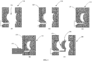
- step 101 shown is a traditional method for an injection molding technique for making optical article 150.
- step 101 cavity 109 of mold 110 is opened.
- step 102 a wafer 120 is placed inside cavity 109 of mold 110.
- step 103 mold 110 is closed.
- step 104 lens material 130 is injected into cavity 109 of mold 110 against wafer 120. After the lens material is sufficiently cooled, mold 110 is opened and lens 150 is ejected from mold 110 at step 105.
- the method depicted in FIG. 1 has disadvantages.
- the most widely available commercial wafers used for injection molding a lens are composed of certain materials, e.g., polycarbonate, tri-acetate cellulose, etc. These materials are not suitable for injection molding an optical article due to poor adhesion resulting from the incompatibility between the wafer materials and the lens material (e.g., Nylon (polyamide), TPU (thermoplastic polyurethane), COC (cyclic olefin copolymer) or COP (cyclic olefin polymer)).
- the lens material e.g., Nylon (polyamide), TPU (thermoplastic polyurethane), COC (cyclic olefin copolymer) or COP (cyclic olefin polymer)
- wafers of Nylon, TPU, COC, and/or COP must be produced first before injecting the lens material to ensure a suitable bond is created between the wafer and the lens material. This process is costly and time consuming.
- step 201 cavity 209 of mold 210 may be moved into an open position.
- various functional wafers may be prepared.
- functional wafer 211 may be prepared as a single layer functional wafer having a first surface 211a and a second surface 211b;
- functional wafer 212 may be prepared as a multi-layer functional wafer having a first outer surface 215, at least one light filtering functional layer 216, and second outer surface 217;
- functional wafer 213 may be prepared having a first protective layer 218 with upper surface 218a, at least one light filtering functional layer 216, and second protective layer 219 with lower surface 219a;
- functional wafer 214 may be prepared as a multi-layer functional wafer having at least one light filtering functional layer 216 and may be coated with adhesion-promoting layer 230.
- wafers 211, 212, 213, 214 may be coated with adhesion-promoting layer 230 on one surface or both surfaces of each wafer, respectively.
- wafers 211, 212, 213, 214 may be coated with adhesion-promoting layer 230 on one surface or both surfaces of each wafer, respectively.
- Wafers 211, 212, 213, and 214 may be coated with the adhesion-promoting layer(s) prior to being inserted into a mold cavity for injection molding.
- functional wafers 211, 212, 213, and 214 may be prepared inside cavity 209 of mold 210.
- step 203 functional wafer 220 is placed inside cavity 209 of mold 210.
- functional wafer 220 may be coated with adhesion-promoting layers 230 on both first and second outer surfaces of functional wafer 220, and functional wafer 220 includes at least one light filtering functional layer 221.
- step 204 mold 210 is closed.
- step 205 lens material 240 is injected into cavity 209 against adhesion-promoting layers 230.
- adhesion-promoting layers 230 facilitate bonding between lens material 240 and functional wafer 220 so that a strong, clear bond occurs between functional wafer 220 and lens material 240.
- mold 210 is opened and optical article 250 is ejected from mold 210.
- optical article 250 includes adhesion-promoting layers 230, at least one light filtering functional layer 221, and lens 241. Furthermore, in this example, exposed adhesion-promoting layer 230 may serve as a primer for subsequent coating operations or to facilitate bonding for an additional overmolding step.
- the injection molding technique depicted in FIG. 2 utilizes adhesion-promoting layer 230 to facilitate the bonding of functional wafer 220 to lens 241, resulting in a clear and strongly bonded optical article 250 despite the potential of functional wafer 220 to be a different material than the material of lens 241.
- a multi-layer functional wafer having a first outer surface 315, at least one light filtering functional layer 316, and second outer surface 317
- functional wafer 313 may be prepared having a first protective layer 318 with upper surface 318a, at least one light filtering functional layer 316, and second protective layer 319 with lower surface 319a
- functional wafer 314 may be prepared as a multi-layer functional wafer having at least one light filtering functional layer 316 and may be coated with adhesion-promoting layer 330.
- wafers 311, 312, 313, 314 may be coated with adhesion-promoting layer 230 on one surface or both surfaces of each wafer, respectively.
- wafers 311, 312, 313, 314 may be coated with adhesion-promoting layer 230 on one surface or both surfaces of each wafer, respectively.
- Wafers 311, 312, 313, and 314 may be coated with the adhesion-promoting layer(s) prior to being inserted into a mold cavity for injection molding.
- functional wafers 311, 312, 313, and 314 may be prepared inside cavity 309 of mold 310.
- step 303 functional wafer 320 is placed inside cavity 309 of mold 310.
- functional wafer 320 may be coated with adhesion-promoting layer 330 on first outer surface of functional wafer 330, and functional wafer 320 includes at least one light filtering functional layer 321.
- step 304 mold 310 is closed.
- step 305 lens material 340 is injected into cavity 309 against adhesion-promoting layer 330. After the lens material has sufficiently solidified, mold 310 is opened and optical article 350 is ejected from mold 310.
- optical article 350 includes adhesion-promoting layer 330, at least one light filtering functional layer 321, and lens 341.
- the injection molding technique depicted in FIG. 3 utilizes adhesion-promoting layer 330 to facilitate the bonding of functional wafer 320 to lens 341, resulting in a clear and strongly bonded optical article 350 regardless of functional wafer 320 being a different material than the material of lens 341.
- the first experiment was conducted using 0.8 mm thick 3.50-base PC/PVA/PC polarizing wafers that were coated with a 5-10 ⁇ m thick layer of UV curable acrylic (Essilor ESSUV) on the concave surface. All the resulting lens laminates not only had very strong bonding between the polarizing wafers and the TPU lenses but also exhibited very good polarization. The resulting lens laminates were subjected to aggressive RX edging without showing any delamination of the wafer from the lens.
- Example 2 Injection Molding of Nylon (Polyamide) polarized lenses
Landscapes
- Engineering & Computer Science (AREA)
- Manufacturing & Machinery (AREA)
- Mechanical Engineering (AREA)
- Health & Medical Sciences (AREA)
- Ophthalmology & Optometry (AREA)
- Injection Moulding Of Plastics Or The Like (AREA)
Abstract
Provided is a method for producing an optical article (250, 350) using an adhesion-promoting layer (230, 330) and injection molding techniques and optical articles (250, 350) having such an adhesion-promoting layer (230, 330). The method disclosed herein include applying the adhesion-promoting layer (230, 330) to a single or multilayered functional wafer (211, 311) to facilitate bonding between the functional wafer (211, 311) and a lens material (240, 340) injected onto functional wafer (211, 311) to form the optical article (250, 350).
Description
- The present disclosure relates generally to methods for making optical articles having single or multi-layer functional wafer and thermoplastic lenses by using adhesion-promoting layers; such methods may include using injection molding methods to produce an optical article.
- Methods of making an optical element through injection molding include injecting a molten lens material against a functional wafer or by overmolding a functional wafer onto a lens. The molten lens material cools to form a lens, and the lens, together with the functional wafer, form an optical article. For optical articles, it is required and important to have a clear, non-hazy, invisible interface and strong adhesion between the functional wafer and the lens. To produce an optical article with these characteristics, the material of the functional wafer needs to be the same or compatible with the material of the lens. For example, if the surface of the functional wafer is not the same material as the lens material or is not compatible with the lens material, the resulting optical article will have poor adhesion between the functional wafer and the lens material and/or the interface between the functional wafer and the lens material will be cloudy and non-clear, both of which are unsuitable for optical lens applications. Since not many clear lens materials are compatible (or miscible) to form an invisible interface and create a strong fuse-bonding with commercially available functional wafers, methods employed by the industry are forced to use functional wafers having the same material as the lens material when making optical elements by injection molding.
- The present disclosure addresses the need for an efficient and cost effective method of making an optical article using single or multi-functional wafers and a thermoplastic lens material. The inventors have found that using an adhesive-promoting layer enables the production of optical articles using widely available single or multi-functional wafers while at the same time ensuring not only an invisible interface but also a strong bond between the single or multi-functional wafer and the lens material, regardless of the materials of the functional wafer and lens.
- In some aspects, an optical article may be provided, the optical article comprising a single or multi-layered functional wafer having: a first outer surface; a second outer surface opposite the first outer surface; and at least one light filtering functional layer disposed between the first outer surface and the second outer surface. At least one of the first outer surface and the second outer surface may be coated with an adhesion-promoting layer. In some aspects, the optical article comprises a lens comprised of a thermoplastic material, the lens being coupled to the optical article via the adhesion-promoting layer. In some aspects, the at least one light filtering functional layer may be a polarizing layer and/or a photochromic layer. The at least one light filtering functional layer may partially block visible light in the 400-500 nm wavelength range, visible light in the 500-700 nm wavelength range, and/or near-infrared light in the 700-1400 nm wavelength range.
- In some aspects, the at least one light filtering functional may be a multi-layer optical film (MOF) filter, for example, a 3M MOF filter. In some aspects, the at least one light filtering functional layer may be a holographic film, for example, a Covestro light filtering functional layer, in which the at least one light filtering functional layer is a spectral filtering layer and provides augmented reality display by reflecting light from a light source embedded in, for example, eye wear associated with the optical article.
- In some aspects, the lens may be coupled to the adhesion-promoting layer using injection molding techniques, and the lens may be a polyamide (PA), a thermoplastic polyurethane (TPU), a polycarbonate (PC), a polymethyl methacrylate (PMMA), a cyclic olefin copolymer (COC), and/or a cyclic olefin polymer (COP). In some aspects, the adhesion-promoting layer may be a UV curable acrylic and/or a polyurethane modified ethoxylated bisphenol A diacrylate.
- In some aspects, the single or multi-layered functional wafer may comprise first and second protective layers, the first and second protective layers defining upper and lower surfaces of the single or multi-functional wafer. The upper and/or lower surface of the single or multi-layered functional wafer may be coated with an adhesion-promoting layer. In some aspects, the at least one light filtering functional layer may be a polyvinyl alcohol (PVA), polyurethane (PU), triacetate cellulose (TAC), or cellulose acetate butyrate (CAB), and the first and second protective layers are polycarbonate (PC) and/or the first and second protective layers are triacetate cellulose (TAC). In some aspects, the first and second protective layers may be polycarbonate (PC), and the adhesion-promoting layer may include a UV curable acrylic and may have a thickness in a range of essentially 1 µm to 10 µm In some aspects, the first and second protective layers may be polycarbonate (PC), and the adhesion-promoting layer may include polyurethane modified ethoxylated bisphenol A diacrylate and may be coated onto the upper surface and the lower surface of the single or multi-layered functional wafer.
- In some aspects, a method for producing an optical article using injection molding comprises the steps of coating an adhesion-promoting layer onto a single or multi-layer functional wafer having: a first outer surface; a second outer surface opposite the first outer surface; and at least one light filtering functional layer disposed between the first outer surface and the second outer surface, where the adhesion-promoting layer coats the first outer surface and/or the second outer surface; inserting the single or multi-layer functional wafer into a mold cavity; and injecting a thermoplastic lens material bonding onto the adhesion-promoting layer to form an optical article, the optical article including: the single or multi-layer functional wafer; the adhesion-promoting layer; and a lens comprising the thermoplastic material. In some aspects, the at least one light filtering functional layer may be a polarizing layer and/or a photochromic layer. In some aspects, the at least one light filtering functional layer may partially block visible light in the 400-500 nm wavelength range, visible light in the 500-700 nm wavelength range, and/or near-infrared light in the 700-1400 nm wavelength range. In some aspects, the thermoplastic lens material may be a polyamide (PA), a thermoplastic polyurethane (TPU), a polycarbonate (PC), a polymethyl methacrylate (PMMA), a cyclic olefin copolymer (COC), and/or (vi) cyclic olefin polymer (COP). In some aspects, the adhesion promoting layer may be a UV curable acrylic, and/or a polyurethane modified ethoxylated bisphenol A diacrylate.
- In other aspects, the single or multi-layer functional wafer may comprise: first and second protective layers with the at least one light filtering functional layer disposed between them, the at least one light filtering functional layer being a (i) polyvinyl alcohol (PVA), (ii) polyurethane (PU), (iii) triacetate cellulose (TAC), or (iv) cellulose acetate butyrate (CAB). In some aspects, the first and second protective layers are polycarbonate (PC), and/or the first and second protective layers are triacetate cellulose (TAC).
- "Optical article," according to the disclosure, is defined as a transparent or translucent object through which a person on one side of the optical article may visually perceive an object on the opposite side. Examples of optical articles include sunglasses, fashion lenses, non-prescription and prescription lenses, sport masks, and goggles.
- Any embodiment of any of the disclosed compositions and/or methods can consist of or consist essentially of-rather than comprise/include/contain/have-any of the described elements and/or features and/or steps. Thus, in any of the claims, the term "consisting of" or "consisting essentially of" can be substituted for any of the open-ended linking verbs recited above, in order to change the scope of a given claim from what it would otherwise be using the open-ended linking verb.
- The term "substantially" and its variations are defined as being largely but not necessarily wholly what is specified as understood by one of ordinary skill in the art, and in one non-limiting embodiment substantially refers to ranges within 10%, within 5%, within 1%, or within 0.5%.
- The term "about" or "approximately" or "substantially unchanged" are defined as being close to as understood by one of ordinary skill in the art, and in one non-limiting embodiment the terms are defined to be within 10%, preferably within 5%, more preferably within 1%, and most preferably within 0.5%.
- The use of the word "a" or "an" when used in conjunction with the term "comprising" in the claims and/or the specification may mean "one," but it is also consistent with the meaning of "one or more," "at least one," and "one or more than one."
- As used in this specification and claim(s), the words "comprising" (and any form of comprising, such as "comprise" and "comprises"), "having" (and any form of having, such as "have" and "has"), "including" (and any form of including, such as "includes" and "include") or "containing" (and any form of containing, such as "contains" and "contain") are inclusive or open-ended and do not exclude additional, unrecited elements or method steps.
- Other objects, features and advantages of the present invention will become apparent from the following detailed description. It should be understood, however, that the detailed description and the examples, while indicating specific embodiments of the invention, are given by way of illustration only. Additionally, it is contemplated that changes and modifications within the spirit and scope of the invention will become apparent to those skilled in the art from this detailed description.
- The following drawings illustrate by way of example and not limitation. For the sake of brevity and clarity, every feature of a given structure is not always labeled in every figure in which that structure appears. Identical reference numbers do not necessarily indicate an identical structure. Rather, the same reference number may be used to indicate a similar feature or a feature with similar functionality, as may non-identical reference numbers. The figures are drawn to scale (unless otherwise noted), meaning the sizes of the depicted elements are accurate relative to each other for at least the embodiment depicted in the figures.
-
FIG. 1 depicts a traditional injection molding technique for making an optical article whereby wafer is placed inside a cavity of a mold before injecting lens material onto the functional wafer. -
FIG. 2 depicts an injection molding technique for making an optical article whereby a single or multi-layered functional wafer is coated with an adhesion-promoting layer before injecting molten plastic onto the functional wafer. -
FIG. 3 depicts a second injection molding technique for making an optical article whereby a single or multi-layered functional wafer is coated with an adhesion-promoting layer before injecting molten plastic onto the functional wafer. - Various features and advantageous details are explained more fully with reference to the non-limiting embodiments that are illustrated in the accompanying drawings and detailed in the following description. It should be understood, however, that the detailed description and the specific examples, while indicating embodiments, are given by way of illustration only, and not by way of limitation. Various substitutions, modifications, additions, and/or rearrangements will be apparent to those of ordinary skill in the art from this disclosure.
- In the following description, numerous specific details are provided to provide a thorough understanding of the disclosed embodiments. One of ordinary skill in the relevant art will recognize, however, that the invention may be practiced without one or more of the specific details, or with other methods, components, materials, and so forth. In other instances, well-known structures, materials, or operations are not shown or described in detail to avoid obscuring aspects of the invention.
- Referring now to
FIG. 1 , shown is a traditional method for an injection molding technique for makingoptical article 150. Instep 101,cavity 109 ofmold 110 is opened. Instep 102, awafer 120 is placed insidecavity 109 ofmold 110. Instep 103,mold 110 is closed. Instep 104,lens material 130 is injected intocavity 109 ofmold 110 againstwafer 120. After the lens material is sufficiently cooled,mold 110 is opened andlens 150 is ejected frommold 110 atstep 105. - In this manner, the method depicted in
FIG. 1 has disadvantages. For example, the most widely available commercial wafers used for injection molding a lens are composed of certain materials, e.g., polycarbonate, tri-acetate cellulose, etc. These materials are not suitable for injection molding an optical article due to poor adhesion resulting from the incompatibility between the wafer materials and the lens material (e.g., Nylon (polyamide), TPU (thermoplastic polyurethane), COC (cyclic olefin copolymer) or COP (cyclic olefin polymer)). Accordingly, to produce a lens composed of commercial available wafers and a lens material using injection molding techniques, wafers of Nylon, TPU, COC, and/or COP must be produced first before injecting the lens material to ensure a suitable bond is created between the wafer and the lens material. This process is costly and time consuming. - Referring now to
FIG. 2 , shown is an injection molding technique for makingoptical article 250 according to one embodiment. For example, atstep 201,cavity 209 ofmold 210 may be moved into an open position. Atstep 202, various functional wafers may be prepared. For example,functional wafer 211 may be prepared as a single layer functional wafer having afirst surface 211a and asecond surface 211b;functional wafer 212 may be prepared as a multi-layer functional wafer having a firstouter surface 215, at least one light filteringfunctional layer 216, and secondouter surface 217;functional wafer 213 may be prepared having a firstprotective layer 218 withupper surface 218a, at least one light filteringfunctional layer 216, and secondprotective layer 219 withlower surface 219a; andfunctional wafer 214 may be prepared as a multi-layer functional wafer having at least one light filteringfunctional layer 216 and may be coated with adhesion-promotinglayer 230. Additionally,wafers layer 230 on one surface or both surfaces of each wafer, respectively. In one aspect,wafers layer 230 on one surface or both surfaces of each wafer, respectively.Wafers functional wafers cavity 209 ofmold 210. - In
step 203,functional wafer 220 is placed insidecavity 209 ofmold 210. In this example,functional wafer 220 may be coated with adhesion-promotinglayers 230 on both first and second outer surfaces offunctional wafer 220, andfunctional wafer 220 includes at least one light filteringfunctional layer 221. Instep 204,mold 210 is closed. Instep 205,lens material 240 is injected intocavity 209 against adhesion-promotinglayers 230. During the injection process, adhesion-promotinglayers 230 facilitate bonding betweenlens material 240 andfunctional wafer 220 so that a strong, clear bond occurs betweenfunctional wafer 220 andlens material 240. After the lens material has sufficiently solidified,mold 210 is opened andoptical article 250 is ejected frommold 210. In this example,optical article 250 includes adhesion-promotinglayers 230, at least one light filteringfunctional layer 221, andlens 241. Furthermore, in this example, exposed adhesion-promotinglayer 230 may serve as a primer for subsequent coating operations or to facilitate bonding for an additional overmolding step. - In this manner, the injection molding technique depicted in
FIG. 2 utilizes adhesion-promotinglayer 230 to facilitate the bonding offunctional wafer 220 tolens 241, resulting in a clear and strongly bondedoptical article 250 despite the potential offunctional wafer 220 to be a different material than the material oflens 241. - Referring now to
FIG. 3 , shown is an injection molding technique for makingoptical article 350 according to one embodiment. For example, atstep 301,cavity 309 ofmold 310 may be moved into an open position. Atstep 303, various functional wafers may be prepared. For example,functional wafer 311 may be prepared as a single layer functional wafer having afirst surface 311a and asecond surface 311b;functional wafer 312 may be prepared as a multi-layer functional wafer having a firstouter surface 315, at least one light filteringfunctional layer 316, and secondouter surface 317;functional wafer 313 may be prepared having a firstprotective layer 318 withupper surface 318a, at least one light filteringfunctional layer 316, and secondprotective layer 319 withlower surface 319a; andfunctional wafer 314 may be prepared as a multi-layer functional wafer having at least one light filteringfunctional layer 316 and may be coated with adhesion-promotinglayer 330. Additionally,wafers layer 230 on one surface or both surfaces of each wafer, respectively. In one aspect,wafers layer 230 on one surface or both surfaces of each wafer, respectively.Wafers functional wafers cavity 309 ofmold 310. - In
step 303,functional wafer 320 is placed insidecavity 309 ofmold 310. In this example,functional wafer 320 may be coated with adhesion-promotinglayer 330 on first outer surface offunctional wafer 330, andfunctional wafer 320 includes at least one light filteringfunctional layer 321. Instep 304,mold 310 is closed. Instep 305,lens material 340 is injected intocavity 309 against adhesion-promotinglayer 330. After the lens material has sufficiently solidified,mold 310 is opened andoptical article 350 is ejected frommold 310. In this example,optical article 350 includes adhesion-promotinglayer 330, at least one light filteringfunctional layer 321, and lens 341. - In this manner, the injection molding technique depicted in
FIG. 3 utilizes adhesion-promotinglayer 330 to facilitate the bonding offunctional wafer 320 to lens 341, resulting in a clear and strongly bondedoptical article 350 regardless offunctional wafer 320 being a different material than the material of lens 341. - Injection molding experiments for making polarizing TPU lenses were performed using a Nissei FN4000 injection molding machine equipped with a 2-cavity φ76mm mold having a 3.25-base concave insert and a 6.10-base convex insert installed in each cavity. Following the operational procedure mentioned above, injection molding trials were carried out using the process parameters listed below:
Material: Lubrizol Isoplast 301Melt temperature: 470 °F Mold temperature: 220 °F Shot size: 60 mm Injection speed: 6% Injection time: 25 seconds Packing pressure: 55% Cooling time: 225 seconds - The first experiment was conducted using 0.8 mm thick 3.50-base PC/PVA/PC polarizing wafers that were coated with a 5-10 µm thick layer of UV curable acrylic (Essilor ESSUV) on the concave surface. All the resulting lens laminates not only had very strong bonding between the polarizing wafers and the TPU lenses but also exhibited very good polarization. The resulting lens laminates were subjected to aggressive RX edging without showing any delamination of the wafer from the lens.
- A second experiment was done with 0.8 mm thick 3.50-base PC/PVA/PC wafers that were coated with polyurethane modified ethoxylated bisphenol A diacrylate on both the concave and the convex surfaces. Again, all the resulting lens laminates had very good polarization and very strong bonding between the polarizing wafers and the TPU lenses. The resulting lens laminates were objected to aggressive RX edging without showing any delamination of the wafer from the lens.
- Injection molding experiments for making polarizing Nylon lenses were performed using a Nissei FN4000 injection molding machine equipped with a 2-cavity φ76mm mold having a 3.25-base concave insert and a 6.10-base convex insert installed in each cavity. Following the operational procedure mentioned above, injection molding trials were carried out using the process parameters listed below:
Material: EMS-Grivory Grilamid Melt temperature: 550 °F Mold temperature: 250 °F Shot size: 63 mm Injection speed: 6% Injection time: 25 seconds Packing pressure: 30% Cooling time: 250 seconds - Similar to Example 1, experiments were conducted using 0.8 mm thick 3.50-base PC/PVA/PC polarizing wafers that were coated with UV curable acrylic (Essilor ESSUV) or on the concave surface or with polyurethane modified ethoxylated bisphenol A diacrylate on both the concave and the convex surfaces. All the resulting lens laminates not only had very strong bonding between the polarizing wafers and the Nylon lenses but also exhibited very good polarization. The resulting lens laminates were subjected to aggressive RX edging without showing any delamination of the wafer from the lens.
- The above specification and examples provide a complete description of the structure and use of illustrative embodiments. Although certain embodiments have been described above with a certain degree of particularity, or with reference to one or more individual embodiments, those skilled in the art could make numerous alterations to the disclosed embodiments without departing from the scope of this invention. As such, the various illustrative embodiments of the methods and systems are not intended to be limited to the particular forms disclosed. Rather, they include all modifications and alternatives falling within the scope of the claims, and embodiments other than the one shown may include some or all of the features of the depicted embodiment. For example, elements may be omitted or combined as a unitary structure, and/or connections may be substituted. Further, where appropriate, aspects of any of the examples described above may be combined with aspects of any of the other examples described to form further examples having comparable or different properties and/or functions, and addressing the same or different problems. Similarly, it will be understood that the benefits and advantages described above may relate to one embodiment or may relate to several embodiments.
- The claims are not to be interpreted as including means-plus- or step-plus-function limitations, unless such a limitation is explicitly recited in a given claim using the phrase(s) "means for" or "step for," respectively.
Claims (15)
- An optical article comprising:a single or multi-layer functional wafer having:a first outer surface;a second outer surface opposite the first outer surface; andat least one light filtering functional layer disposed between the first outer surface and the second outer surface, wherein at least one of the first outer surface and the second outer surface is coated with an adhesion-promoting layer; anda lens comprising a thermoplastic material, the lens coupled to the optical article via the adhesion-promoting layer.
- The optical article of claim 1, wherein the at least one light filtering functional layer is (i) a polarizing layer and/or (ii) a photochromic layer.
- The optical article of claim 1, wherein the at least one light filtering functional layer partially blocks at least one of: (i) visible light in the 400-500 nm wavelength range; (ii) visible light in the 500-700 nm wavelength range; and (iii) near-infrared light in the 700-1400 nm wavelength range.
- The optical article of claim 1, wherein the lens is coupled to the adhesion-promoting layer using injection molding techniques, and the lens is at least one of a (i) polyamide (PA); (ii) thermoplastic polyurethane (TPU); (iii) polycarbonate (PC); (iv) polymethyl methacrylate (PMMA); (v) cyclic olefin copolymer (COC); and (vi) cyclic olefin polymer (COP).
- The optical article of claim 1, wherein the adhesion-promoting layer is at least one of (i) a UV curable acrylic; and (ii) a polyurethane modified ethoxylated bisphenol A diacrylate.
- The optical article of claim 1, wherein the single or multi-layer functional wafer comprises first and second protective layers, the first and second protective layers defining upper and lower surfaces of the single or multi-layer functional wafer, and wherein the upper and/or lower surface of the single or multi-layer functional wafer is coated with an adhesion-promoting layer.
- The optical article of claim 6, wherein the at least one light filtering functional layer is a (i) polyvinyl alcohol (PVA); (ii) polyurethane (PU); (iii) triacetate cellulose (TAC); or (iv) cellulose acetate butyrate (CAB), and wherein at least one of (i) the first and second protective layers are polycarbonate (PC), and/or (ii) the first and second protective layers are triacetate cellulose (TAC).
- The optical article of claim 6, wherein the first and second protective layers are polycarbonate (PC), wherein the adhesion-promoting layer includes a UV curable acrylic, and wherein the adhesion-promoting layer has a thickness in a range of essentially 1 µm to 10 µm.
- The optical article of claim 6, wherein the first and second protective layers are polycarbonate (PC), wherein the adhesion-promoting layer includes polyurethane modified ethoxylated bisphenol A diacrylate, and wherein the adhesion-promoting layer is coated onto the upper surface and the lower surface of the single or multi-layer functional wafer.
- A method for producing an optical article using injection molding, the method comprising:(a) coating an adhesion-promoting layer onto a single or multi-layer functional wafer having:a first outer surface; a second outer surface opposite the first outer surface; andat least one light filtering functional layer disposed between the first outer surface and the second outer surface, wherein the adhesion-promoting layer coats at least one of the first outer surface and the second outer surface;(b) inserting the single or multi-layer functional wafer into a mold cavity; and(c) injecting a thermoplastic lens material bonding onto the adhesion-promoting layer to form an optical article, the optical article including:the single or multi-layer functional wafer;the adhesion-promoting layer; anda lens comprising the thermoplastic material.
- The method of claim 10, wherein the at least one light filtering functional layer is (i) a polarizing layer and/or (ii) a photochromic layer.
- The method of claim 10, wherein the at least one light filtering functional layer partially blocks at least one of: (i) visible light in the 400-500 nm wavelength range; (ii) visible light in the 500-700 nm wavelength range; and/or (iii) near-infrared light in the 700-1400 nm wavelength range.
- The method of claim 10, wherein the thermoplastic lens material is at least one of a (i) polyamide (PA); (ii) thermoplastic polyurethane (TPU); (iii) polycarbonate (PC); (iv) polymethyl methacrylate (PMMA); (v) cyclic olefin copolymer (COC); and (vi) cyclic olefin polymer (COP).
- The method of claim 10, wherein the adhesion-promoting layer is at least one of (i) a UV curable acrylic; and (ii) a polyurethane modified ethoxylated bisphenol A diacrylate.
- The method of claim 10, wherein the single or multi-layer functional wafer comprises first and second protective layers with the at least one light filtering functional layer disposed between them, and wherein the at least one light filtering functional layer is a (i) polyvinyl alcohol (PVA); (ii) polyurethane (PU); (iii) triacetate cellulose (TAC); or (iv) cellulose acetate butyrate (CAB); and wherein at least one of (i) the first and second protective layers are polycarbonate (PC), and (ii) the first and second protective layers are triacetate cellulose (TAC).
Priority Applications (1)
| Application Number | Priority Date | Filing Date | Title |
|---|---|---|---|
| EP17306036.9A EP3437845A1 (en) | 2017-08-03 | 2017-08-03 | Method for making polarized and photochromic thermoplastic lenses |
Applications Claiming Priority (1)
| Application Number | Priority Date | Filing Date | Title |
|---|---|---|---|
| EP17306036.9A EP3437845A1 (en) | 2017-08-03 | 2017-08-03 | Method for making polarized and photochromic thermoplastic lenses |
Publications (1)
| Publication Number | Publication Date |
|---|---|
| EP3437845A1 true EP3437845A1 (en) | 2019-02-06 |
Family
ID=59699638
Family Applications (1)
| Application Number | Title | Priority Date | Filing Date |
|---|---|---|---|
| EP17306036.9A Withdrawn EP3437845A1 (en) | 2017-08-03 | 2017-08-03 | Method for making polarized and photochromic thermoplastic lenses |
Country Status (1)
| Country | Link |
|---|---|
| EP (1) | EP3437845A1 (en) |
Cited By (7)
| Publication number | Priority date | Publication date | Assignee | Title |
|---|---|---|---|---|
| WO2021198374A1 (en) * | 2020-03-31 | 2021-10-07 | Essilor International | Functional wafers by 3d printing |
| EP3910411A1 (en) * | 2020-05-13 | 2021-11-17 | Essilor International | Primer for ophthalmic lenses |
| US20220276409A1 (en) * | 2019-07-02 | 2022-09-01 | Essilor International | Method for Making Optical Lenses Using 3D Printed Functional Wafers |
| EP4079481A1 (en) * | 2021-04-22 | 2022-10-26 | Essilor International | Method and apparatus for adjusting recess depth of a mold insert |
| US12226968B2 (en) | 2019-07-02 | 2025-02-18 | Essilor International | Injection overmolding with heat/cool cycling for making optical lenses using 3D-printed functional wafers |
| US12226951B2 (en) | 2019-07-02 | 2025-02-18 | Essilor International | FDM 3D printing of optical lens with high clarity and mechanical strength |
| EP4737104A1 (en) * | 2024-10-29 | 2026-05-06 | Essilor International | Method for manufacturing an optical article for controlling eye-length related disorders with light filtering functions |
Citations (6)
| Publication number | Priority date | Publication date | Assignee | Title |
|---|---|---|---|---|
| US5702813A (en) * | 1994-08-12 | 1997-12-30 | Yamamoto Kogaku Co., Ltd. | Composite molded article including a polarizer of polycarbonate |
| US5800744A (en) * | 1996-08-13 | 1998-09-01 | Munakata; Yoshikazu | Method for producing a dioptric photocromic semi-finished lens |
| US20070270062A1 (en) * | 2006-05-19 | 2007-11-22 | Steven Weber | Process and System for Applying a Coating onto a Surface of a Lens Substrate |
| US20090283924A1 (en) * | 2008-05-14 | 2009-11-19 | Peiqi Jiang | Method for post-injection in mold lamination with an adhesively coated functionalized film |
| US20110090454A1 (en) * | 2009-05-15 | 2011-04-21 | Johnson David A | Curved corrective lenses configured to decode three-dimensional content |
| US20170205639A1 (en) * | 2010-04-15 | 2017-07-20 | Oakley, Inc. | Eyewear with chroma enhancement |
-
2017
- 2017-08-03 EP EP17306036.9A patent/EP3437845A1/en not_active Withdrawn
Patent Citations (6)
| Publication number | Priority date | Publication date | Assignee | Title |
|---|---|---|---|---|
| US5702813A (en) * | 1994-08-12 | 1997-12-30 | Yamamoto Kogaku Co., Ltd. | Composite molded article including a polarizer of polycarbonate |
| US5800744A (en) * | 1996-08-13 | 1998-09-01 | Munakata; Yoshikazu | Method for producing a dioptric photocromic semi-finished lens |
| US20070270062A1 (en) * | 2006-05-19 | 2007-11-22 | Steven Weber | Process and System for Applying a Coating onto a Surface of a Lens Substrate |
| US20090283924A1 (en) * | 2008-05-14 | 2009-11-19 | Peiqi Jiang | Method for post-injection in mold lamination with an adhesively coated functionalized film |
| US20110090454A1 (en) * | 2009-05-15 | 2011-04-21 | Johnson David A | Curved corrective lenses configured to decode three-dimensional content |
| US20170205639A1 (en) * | 2010-04-15 | 2017-07-20 | Oakley, Inc. | Eyewear with chroma enhancement |
Cited By (13)
| Publication number | Priority date | Publication date | Assignee | Title |
|---|---|---|---|---|
| US12226968B2 (en) | 2019-07-02 | 2025-02-18 | Essilor International | Injection overmolding with heat/cool cycling for making optical lenses using 3D-printed functional wafers |
| US20220276409A1 (en) * | 2019-07-02 | 2022-09-01 | Essilor International | Method for Making Optical Lenses Using 3D Printed Functional Wafers |
| US12226951B2 (en) | 2019-07-02 | 2025-02-18 | Essilor International | FDM 3D printing of optical lens with high clarity and mechanical strength |
| WO2021198374A1 (en) * | 2020-03-31 | 2021-10-07 | Essilor International | Functional wafers by 3d printing |
| US12233611B2 (en) | 2020-03-31 | 2025-02-25 | Essilor International | Functional wafers by 3D printing |
| US12461389B2 (en) | 2020-05-13 | 2025-11-04 | Essilor International | Primer for ophthalmic lenses |
| EP3910411A1 (en) * | 2020-05-13 | 2021-11-17 | Essilor International | Primer for ophthalmic lenses |
| CN117120233A (en) * | 2021-04-22 | 2023-11-24 | 依视路国际公司 | Method and apparatus for adjusting recess depth of mold insert |
| WO2022223475A1 (en) * | 2021-04-22 | 2022-10-27 | Essilor International | Method and apparatus for adjusting recess depth of a mold insert |
| EP4079481A1 (en) * | 2021-04-22 | 2022-10-26 | Essilor International | Method and apparatus for adjusting recess depth of a mold insert |
| US12605869B2 (en) | 2021-04-22 | 2026-04-21 | Essilor International | Method and apparatus for adjusting recess depth of a mold insert |
| EP4737104A1 (en) * | 2024-10-29 | 2026-05-06 | Essilor International | Method for manufacturing an optical article for controlling eye-length related disorders with light filtering functions |
| WO2026092899A1 (en) * | 2024-10-29 | 2026-05-07 | Essilor International | Method for manufacturing an optical article for controlling eye-length related disorders with light filtering functions |
Similar Documents
| Publication | Publication Date | Title |
|---|---|---|
| JP5684461B2 (en) | Method of manufacturing a polarizing optical article | |
| EP2119553A2 (en) | Method for laminating a film onto an injection moulded lens | |
| EP3449309B1 (en) | High refractive index polarized spectacle lens | |
| US20150331259A1 (en) | Film Laminated Ophthalmic Lenses with Improved Wheel Edging Performance | |
| US10274749B2 (en) | Producing microstructured spectacle lenses by means of transfer layer | |
| US20150277144A1 (en) | Production of opththalmic lenses with protected microstructures | |
| US20050117113A1 (en) | Method of making a thermoplastic-based article and a thermoplastic-based article made thereby | |
| CN109130260A (en) | Manufacture the method and polarization optics product of polarization optics product | |
| US11994756B2 (en) | Method for making a gradient color polar lens with a non-polar near vision zone | |
| CN104272141B (en) | Method for manufacturing polarizing lens and polarizing lens obtained by said method | |
| US12379522B2 (en) | Integrated depth sensor window lens and method | |
| JP2021531999A (en) | Improved molding equipment for casting and molding optical articles with wafers on top, corresponding methods and optical articles | |
| US20160209554A1 (en) | Fabrication Method of Lens Substrate Having Anti-Fog Film Layer and Structure Thereof | |
| US7022268B2 (en) | Process for moulding a lens having an insert | |
| US12591148B2 (en) | Eyeglass lens with decorative element | |
| CN103402743B (en) | For producing the method for polarized lenses and corresponding polarized lenses | |
| JP6211471B2 (en) | Polarized optical article and method for manufacturing the same | |
| KR100528394B1 (en) | Base sheet of polarizing 0ptical lens and method of manufacturing the same | |
| JP2025534804A (en) | METHOD FOR MANUFACTURING A TRANSPARENT PLASTIC LENS HAVING EMBEDDED DECORATIVE ELEMENTS | |
| KR20250111299A (en) | Peelable liner for protecting optical wafers | |
| JP2025536588A (en) | Polarized PVA wafer for reducing optical distortion | |
| KR20240119257A (en) | Ophthalmic element comprising a film structure comprising an auxetic film | |
| US20160297155A1 (en) | Methods for Manufacturing Articles Comprising Photochromic Film |
Legal Events
| Date | Code | Title | Description |
|---|---|---|---|
| PUAI | Public reference made under article 153(3) epc to a published international application that has entered the european phase |
Free format text: ORIGINAL CODE: 0009012 |
|
| STAA | Information on the status of an ep patent application or granted ep patent |
Free format text: STATUS: THE APPLICATION HAS BEEN PUBLISHED |
|
| AK | Designated contracting states |
Kind code of ref document: A1 Designated state(s): AL AT BE BG CH CY CZ DE DK EE ES FI FR GB GR HR HU IE IS IT LI LT LU LV MC MK MT NL NO PL PT RO RS SE SI SK SM TR |
|
| AX | Request for extension of the european patent |
Extension state: BA ME |
|
| STAA | Information on the status of an ep patent application or granted ep patent |
Free format text: STATUS: THE APPLICATION IS DEEMED TO BE WITHDRAWN |
|
| 18D | Application deemed to be withdrawn |
Effective date: 20190807 |