EP3437801A1 - Impact tool angular velocity measurement system - Google Patents
Impact tool angular velocity measurement system Download PDFInfo
- Publication number
- EP3437801A1 EP3437801A1 EP18186687.2A EP18186687A EP3437801A1 EP 3437801 A1 EP3437801 A1 EP 3437801A1 EP 18186687 A EP18186687 A EP 18186687A EP 3437801 A1 EP3437801 A1 EP 3437801A1
- Authority
- EP
- European Patent Office
- Prior art keywords
- hammer
- anvil
- impact tool
- angle sensor
- impact
- Prior art date
- Legal status (The legal status is an assumption and is not a legal conclusion. Google has not performed a legal analysis and makes no representation as to the accuracy of the status listed.)
- Granted
Links
Images


Classifications
-
- B—PERFORMING OPERATIONS; TRANSPORTING
- B25—HAND TOOLS; PORTABLE POWER-DRIVEN TOOLS; MANIPULATORS
- B25B—TOOLS OR BENCH DEVICES NOT OTHERWISE PROVIDED FOR, FOR FASTENING, CONNECTING, DISENGAGING, OR HOLDING
- B25B23/00—Details of, or accessories for, spanners, wrenches, screwdrivers
- B25B23/14—Arrangement of torque limiters or torque indicators in wrenches or screwdrivers
- B25B23/147—Arrangement of torque limiters or torque indicators in wrenches or screwdrivers specially adapted for electrically operated wrenches or screwdrivers
- B25B23/1475—Arrangement of torque limiters or torque indicators in wrenches or screwdrivers specially adapted for electrically operated wrenches or screwdrivers for impact wrenches or screwdrivers
-
- B—PERFORMING OPERATIONS; TRANSPORTING
- B25—HAND TOOLS; PORTABLE POWER-DRIVEN TOOLS; MANIPULATORS
- B25D—PERCUSSIVE TOOLS
- B25D16/00—Portable percussive machines with superimposed rotation, the rotational movement of the output shaft of a motor being modified to generate axial impacts on the tool bit
-
- B—PERFORMING OPERATIONS; TRANSPORTING
- B25—HAND TOOLS; PORTABLE POWER-DRIVEN TOOLS; MANIPULATORS
- B25B—TOOLS OR BENCH DEVICES NOT OTHERWISE PROVIDED FOR, FOR FASTENING, CONNECTING, DISENGAGING, OR HOLDING
- B25B21/00—Portable power-driven screw or nut setting or loosening tools; Attachments for drilling apparatus serving the same purpose
- B25B21/02—Portable power-driven screw or nut setting or loosening tools; Attachments for drilling apparatus serving the same purpose with means for imparting impact to screwdriver blade or nut socket
-
- B—PERFORMING OPERATIONS; TRANSPORTING
- B25—HAND TOOLS; PORTABLE POWER-DRIVEN TOOLS; MANIPULATORS
- B25B—TOOLS OR BENCH DEVICES NOT OTHERWISE PROVIDED FOR, FOR FASTENING, CONNECTING, DISENGAGING, OR HOLDING
- B25B21/00—Portable power-driven screw or nut setting or loosening tools; Attachments for drilling apparatus serving the same purpose
- B25B21/02—Portable power-driven screw or nut setting or loosening tools; Attachments for drilling apparatus serving the same purpose with means for imparting impact to screwdriver blade or nut socket
- B25B21/026—Impact clutches
-
- B—PERFORMING OPERATIONS; TRANSPORTING
- B25—HAND TOOLS; PORTABLE POWER-DRIVEN TOOLS; MANIPULATORS
- B25D—PERCUSSIVE TOOLS
- B25D11/00—Portable percussive tools with electromotor or other motor drive
- B25D11/04—Portable percussive tools with electromotor or other motor drive in which the tool bit or anvil is hit by an impulse member
-
- B—PERFORMING OPERATIONS; TRANSPORTING
- B25—HAND TOOLS; PORTABLE POWER-DRIVEN TOOLS; MANIPULATORS
- B25D—PERCUSSIVE TOOLS
- B25D17/00—Details of, or accessories for, portable power-driven percussive tools
Definitions
- the present disclosure relates, generally, to impact tools and, more particularly, to a mechanism that measures the angular velocity of components in the impact tool.
- An illustrative embodiment of the present disclosure provides an impact tool which comprises: an impact force generation unit that includes a hammer that is movable in a first direction and which applies a rotational impact force on an anvil that rotates the output drive; a first hammer angle sensor set to a first signal channel and located proximate to a surface of the hammer, and a second hammer angle sensor set to a second signal channel and located proximate to the surface of the hammer and adjacent to first hammer angle sensor; a plurality of regularly spaced targets located on the surface of the hammer; wherein each of the plurality of regularly spaced targets are detectable by the first and second hammer sensors; wherein detection of one or more of the plurality of regularly spaced targets by the first and second hammer sensors indicates movement of the hammer; a first anvil angle sensor set to a third signal channel and located proximate to a surface of the anvil, and a second anvil angle sensor set to a fourth signal channel and located
- an impact tool which comprises: a drive source configured to rotate an output drive; an impact force generation unit that includes a hammer that is movable in a first direction to apply a rotational impact force on an anvil which rotates the output drive; a first hammer angle sensor set to a first signal channel located proximate to a surface of the hammer, and a second hammer angle sensor set to a second signal channel also located proximate to the surface of the hammer and adjacent to first hammer angle sensor; a plurality of regularly spaced targets located on the surface of the hammer; wherein each of the plurality of regularly spaced targets are detectable by the first and second hammer sensors; wherein detection of one or more of the plurality of regularly spaced targets by the first and second hammer sensors indicates rotation of the hammer; and a controller configured to receive and process a plurality of signals generated by the first and second hammer angle sensors to determine the angular velocity of the output drive.
- the impact tool may further include any one or more of the following: the first and second hammer sensors being configured to detect movement of the hammer in a second direction opposite the first direction after the hammer impacts the anvil; an anvil angle sensor and a plurality of regularly spaced anvil targets mounted on a surface of the anvil; the anvil angle sensor being located proximate to the surface of the anvil, wherein each of the plurality of regularly spaced anvil targets are detectable by the anvil angle sensor, and wherein the controller being configured to receive and process a plurality of signals also generated by the anvil angle sensor to determine the angular velocity of the output drive; a three axis gyroscopic sensor mounted within a tool housing portion of the impact tool, wherein the three axis gyroscopic sensor detects housing rotation about an axis coincident with an axis of rotation of the output drive, and wherein the controller being configured to receive gyroscopic signals to assist in determining the ang
- An illustrative embodiment of the present disclosure provides an impact tool which comprises: a drive source configured to rotate an output drive; a hammer that is movable in a first direction to apply a rotational impact force on an anvil which rotates the output drive; a first hammer angle sensor set to a first signal channel and located proximate to a surface of the hammer; a plurality of regularly spaced targets located on the surface of the hammer; wherein each of the plurality of regularly spaced targets are detectable by the first hammer sensor; and wherein detection of one or more of the plurality of regularly spaced targets by the first hammer sensor indicates movement of the hammer.
- the impact tool may further include any one or more of the following: a controller configured to receive and process a plurality of signals generated by the first hammer angle sensor to determine the angular velocity of the hammer; a second hammer angle sensor set to a second signal channel also located proximate to the surface of the hammer and adjacent to first hammer angle sensor; the first and second hammer sensors being configured to detect rotation of the hammer in a second direction opposite the first direction after the hammer impacts the anvil; an anvil angle sensor and a plurality of regularly spaced anvil targets mounted on a surface of the anvil; the anvil angle sensor is located proximate to the surface of the anvil, wherein each of the plurality of regularly spaced anvil targets being detectable by the anvil angle sensor, and wherein the controller is configured to receive and process a plurality of signals also generated by the anvil angle sensor to determine the angle and velocity of the output drive; and a three axis gy
- An illustrative embodiment of the present disclosure provides electronic detectors, encoders, or sensors (referred to general as detectors) added to at least the hammer, and a controller to monitor the function of an impact wrench.
- detectors are added to both the hammer and the anvil. These detectors monitor anvil rotation and hammer velocity. These signals are processed by a controller which determines the incremental bolt angle that occurs during each impact between the hammer and anvil. The controller then calculates the quantity of energy that has been delivered to the fastener.
- An embodiment of the angular velocity measurement mechanism may include, but is not limited to, one or more of the following features: measuring the forward hammer velocity just prior to impact between the hammer and anvil and reverse velocity immediately after impact between the hammer and anvil to determine the amount of energy that left the tool during impact; measuring the sudden change of rate of angular velocity of the anvil used to detect when an impact between the hammer and anvil has occurred; measuring the incremental anvil angle associated with a single impact between the hammer and anvil to determine the fastener or bolt rotation from that impact; and measuring the cumulative anvil angle used during a fastening cycle to determine total angle the fastener or bolt was rotated.
- the controller calculates hammer velocity before and after each impact between the hammer and anvil. Given the rotational velocity of the hammer, and the rotational inertia of the hammer, it is possible to calculate the angular kinetic energy in the hammer illustratively by the formula one-half multiplied by the angular velocity multiplied by the moment of inertia squared ( i.e ., 1 2 I w 2 ) . These velocity measurements may then be used to determine how much energy has left the impact mechanism and transmitted forward into the socket.
- the angle of rotation of the fastener or bolt may be determined by measuring the angle of rotation of the impact tool's anvil. Since the tool anvil and bolt head are directly connected by the socket, the angle of rotation of the bolt should be substantially the same as that of the anvil. Using an anvil angle encoder signal generated by the detector, the controller may calculate both the incremental angle that occurs during each impact, and the cumulative angle of anvil rotation of the bolt.
- FIG. 1 A cross-sectional view of an illustrative embodiment of an impact tool 2 is shown in Fig. 1 .
- This view of impact tool 2 includes housing 4 that contains motor 6 that drives a rotating rod 8 which drives gear set assembly 10.
- gear set assembly 10 rotates cam shaft 12.
- Rotating hammer 14 draws it against the bias of spring 18 illustratively in direction 20 until hammer 14 is released moving it in direction 22 as well as rotates about an axis 24.
- Hammer 14 impacts anvil 26 causing same to rotate. Continuing this process causes hammer 14 to create continuous intermittent impacts against anvil 26 causing it to continually rotate.
- Output drive 28 extends from anvil 26 and can receive a connector or other device that engages a fastener or bolt to tighten or loosen same.
- a plurality of detectors such as detector 30 shown in Fig. 1 (see, also, detector 32 in Figs. 2 and 3 ) is attached to hammer case portion 34 of housing 4 of impact tool 2. It is appreciated that hammer case portion 34 may either be a separate structure or an integrally formed part of housing 4.
- Detector 30 is intended to be located in proximity to hammer 14.
- detectors or sensors may be rotary, incremental, shaft and/or quadrature encoders.
- two encoders (such as detectors 30 and 32) may be used, each having a unique channel output. Each encoder transmits pulses when the hammer is moving.
- an encoder with two channels allows not only measures position of the hammer but also direction and speed.
- these encoders, sensors, etc. will be herein generally referred to as detector.
- the encoders for the hammer and anvil may operate the same.
- Each of these encoders may have a minimum of two channels, as needed, to determine direction of rotation. These channels are phase shifted from each other by 90 degrees.
- the encoders may be replaced with resolvers.
- a two channel resolver may operate similar to an encoder, except the output from each sensor is an analog signal instead of digital signal.
- detector set 36 and 37 may be attached to hammer case 34 or like structure. Detectors 36 and 37 are located in proximity of a portion of anvil 26 (see, also, Fig. 3 ). In this illustrative embodiment, and as will be discussed in more detail herein, detectors 36 and 37 are configured to detect the angular movement of anvil 26. It will be appreciated by the skilled artisan upon reading this disclosure that detectors 30, 32, 36, and 37 may be electrically connected to a controller 33.
- Fig. 1 Also shown in Fig. 1 is handle assembly 38.
- Trigger 40 part of handle assembly 38, actuates motor 6 in order to rotate output drive 28.
- Controller 33 in one embodiment may be located onboard impact tool 2 in handle assembly 38. In another embodiment, controller 33 may be located remotely from impact tool 2.
- a power supply 42 may be attached to handle assembly 38 to supply power to motor 6 and any other electrical systems onboard impact tool 2.
- power supply 42 may be a 20-amp or greater lithium battery, for example, to provide sufficient power to the power tool 2.
- impact tool 2 may be supplied with power via a power supply cord also connected to a power supply outlet or other power source.
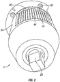
- FIG. 2 A front perspective view of impact tool 2 with a portion of its hammer case 34 removed is shown in Fig. 2 .
- This view depicts how detectors 30 and 32 are illustratively positioned relative to each other and to hammer 14.
- a plurality of markings 44 such as line markers or other indicia on hammer 14 may be read or otherwise detected by detectors 30 and 32 in order to read the positioning of hammer 14.
- each detector is electrically phase shifted from each other defining different channels as previously discussed. In this way, the detectors can determine in which direction hammer 14 is travelling and at what speed. These measurements may then be used to determine the amount of energy that may be delivered to the fastener that is being rotated by output drive 28.
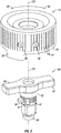
- FIG. 3 An isolated exploded view of hammer 14 and anvil 26 are shown in Fig. 3 . Also depicted in this view are detectors 30, 32 located in proximity of hammer 14 and detectors 36 and 37 located in proximity of anvil 26. Markings such as encoder lines 44 are regularly spaced about outer surface 46 of hammer 14 as illustratively shown. It will be appreciated by the skilled artisan upon reading this disclosure that such lines 44 may be placed on surface 46 in any variety of ways that allow detectors 30 and 32 to detect them. For example, lines 44 may be cut or scribed into surface 46, or may be cut into surface 46 and filled with ink or a magnetic material readable by certain detectors. Alternatively, lines 44 may take the form of an optically readable characteristic for certain detectors.
- any such variety of known readable markings may be placed on hammer 14. All that is necessary is that the markings have characteristics that can be detected by the detector. As such, the two detectors 30 and 32 are phase shifted from each other and are able to detect the markings. The will be able to detect whether hammer 14 is rotating in either direction 48 or 50. Accordingly, by embedding or otherwise placing the detectors on hammer case 34 or other location in proximity of hammer 14 sufficient to detect movement of same, detectors 30 and 32 with lines 44 or other markings, structures, or indicia, may detect the angular or rotational movement of hammer 14 in either direction.
- surface 52 of anvil 26 includes a plurality of markings 54 that are regularly spaced thereabout and configured to be read by detectors 36 and 37 are illustratively composed of two channels.
- Detectors 36 and 37 may operate similar to that described with respect to detectors 30 and 32.
- anvil 26 may be extended either axially or radially to accommodate the markings, and to ensure sufficient proximity between surface 52 and detectors 36 and 37.
- hammer 14 includes jaws 56 (jaws 58 is shown in Figs. 6 and 7 ) which is configured to strike either of flanges 60 or 62 on anvil 26. Accordingly, as hammer 14 rotates, the amount of that rotation is being detected by detectors 30 and 32. As jaws 56 (as well as head 58) strike either of flanges 60 and 62, anvil 26 is caused to rotate as well. Detectors 36 and 37 measure the angle of rotation of anvil 26 based on how many markings 54 are read. The net effect of this is that the controller can receive data about how much the hammer is rotating, and how much the anvil is rotating in response to being struck by the hammer.
- impact tool 2 may include a three axis gyroscopic sensor located thereon. This sensor measures the rotation of the housing about axis 24.
- the three axis gyroscopic sensor may be part of the circuit board of controller 33.
- controller 33 may be configured to receive these signals from the hammer, anvil, and gyroscopic sensor to determine the angular velocity of the hammer and/or anvil. And because the anvil, through the connected output drive, is connected to the fastener or bolt, the rotational velocity of the fastener or bolt can be determined as well.
- An accelerometer may be added to the circuit board of controller 33 on impact tool 2 in order to send a signal to controller 33 indicative of an impact between the hammer and anvil. It will be appreciated by a skilled artisan that the accelerometer may be mounted anywhere inside the tool housing in proximity to the impact mechanism. The shock wave created by the impact action of the mechanism is transmitted within the housing and creates a detectable spike in the output of the accelerometer. This signal may be used by the controller as an indication that an impact has occurred.
- a motor current transducer sensor may be added to the circuit board of controller 33 and configured to send an input signal to controller 33.
- Motor current is proportional to motor torque and can be used to determine how much torque is being delivered to the gearing and impact mechanisms.
- Controller 33 whether located on impact tool 2 or spaced apart, is contemplated to be configured to include storage for these signals received from such detectors.
- Impact tool 2 may include a user interface that includes a display, push buttons, audible notifications, and/or LED lighting, for example, to allow adjustment of the functional settings for the impact tool.
- a selector switch may be attached to impact tool 2 in order to allow individual socket size setting. Further, strain gages may be attached to the anvil to measure torque of same.
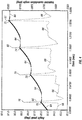
- a graph of the hammer angle signal 64 and anvil angle signal 66 values plotted against time is shown in Fig. 4 .
- Angle is represented in units of radians on the Y axis and time is represented in units of seconds on the X axis. This trace was produced by the signals from hammer 14 detectors 30, 32, and the anvil signals generated by detectors 36 and 37. Peaks 70, 72, 74, and 75 on lines 64 and 66 represent the impact of jaws 56 and 58 against respective jaw flanges 60 and 62 to rotate anvil 26.
- the value of the angular position read by the controller 33 is incremented.
- the revised angle reading can be either greater or less than the previous angle value, depending on which direction the component is rotating.
- the portion of time represented in Fig. 4 is limited to four impact events. These angle traces were collected while the tool was tightening a fastener which had already been partially tightened. From this graph the behavior and action of anvil 26 and hammer 14 may be studied. The hammer velocity increases until the hammer jaws 56 and 58 engage anvil jaw flanges 60 and 62 to cause anvil 26 to also rotate forward. This sudden connection of rotating hammer 14 to anvil 26 (and connected output drive) constitutes an impact event. Impact events occur twice per revolution of hammer 14. At the point in time when the impact occurs, the anvil angle signal indicates a sudden change from zero velocity to a very high velocity in the forward direction.
- the sudden acceleration is indicated graphically by the vertical trace, ending in peaks 76, 78, 80, and 81.
- rotational kinetic energy is delivered from hammer 14 to anvil 26 and the connected output drive.
- the connected output drive includes some rotational elasticity which temporarily stores a portion of the delivered energy which left the hammer. Some of the energy which leaves the hammer is consumed while rotating the fastener. Some energy may be consumed due to losses in the connected output drive.
- the portion of energy temporarily stored in the connected output drive applies a torque to drive the anvil and hammer in the reverse direction 50.
- Both the hammer and anvil rotate in the reverse direction briefly, until the torque delivered by the motor overcomes the inertia in the hammer and causes it to begin rotating in the forward direction again.
- This series of steps describe the process of impacting.
- the anvil and hammer angle signals are sent to controller 33, and can be used to determine many different attributes about the operation of the impact mechanism. Some of the attributes that can be calculated include hammer energy before impact, hammer energy after impact, deflection of the connected output drive, rebound velocity of the connected output drive, and rebound velocity of the hammer. These attributes can be used to calculate the status of bolt torque during the fastening process. Controller 33 can make the decision to stop the motor when a targeted torque has been reached.
- FIG. 5 depicts rotating hammer 14 located at a position just prior to impacting anvil 26.
- a reference marker 82 is highlighted for demonstrable purposes to allow it to be followed through hammer 14's rotation and impact against anvil 26.
- hammer 14 along with jaw 56 (as well as head 58 not shown in this view) is located above jaw flanges 60 and 62 of anvil 26.
- the approximate corresponding position of hammer 14 on line 64 from the chart of Fig. 4 is shown at position 88.
- Hammer 14 continues rotating illustratively in direction 48 and in direction 86 until, as shown in Fig. 6 , jaws 56 and 58 strike jaw flanges 60 and 62, respectively.
- reference marker 82 has rotated around with hammer 14 in direction 48 and ends up at this location as hammer 14 and anvil 26 impact each other. This position is depicted on the chart at peak 72 on line 64 for hammer 14 and peak 78 on line 66 for anvil 26. After this impact, however, line 64 demonstrates what happens to hammer 14.
- reference marker 82 (based on readings from detectors 30 and 32) demonstrates hammer 14 rebounds back in direction 50 opposite of direction 48. Hammer 14 also moves in direction 84 away from anvil 26. The corresponding location on line 64 of the accompanying chart is represented at position 90. As depicted by this chart, the rotational angle of hammer 14 is shown not continuing moving upwards immediately after striking anvil 26. Instead, line 64 moves downwards at 90. After that rebounding period, hammer 14 proceeds again to move upwards corresponding to hammer 14 moving in direction 48 again. As a result, the chart in Fig. 4 , and as part of Figs. 5, 6, and 7 , demonstrates that detectors 30 and 32 measure the rebounding effect exhibited by hammer 14.
Landscapes
- Engineering & Computer Science (AREA)
- Mechanical Engineering (AREA)
- Percussive Tools And Related Accessories (AREA)
- Details Of Spanners, Wrenches, And Screw Drivers And Accessories (AREA)
Abstract
Description
- The present disclosure relates, generally, to impact tools and, more particularly, to a mechanism that measures the angular velocity of components in the impact tool.
- An illustrative embodiment of the present disclosure provides an impact tool which comprises: an impact force generation unit that includes a hammer that is movable in a first direction and which applies a rotational impact force on an anvil that rotates the output drive; a first hammer angle sensor set to a first signal channel and located proximate to a surface of the hammer, and a second hammer angle sensor set to a second signal channel and located proximate to the surface of the hammer and adjacent to first hammer angle sensor; a plurality of regularly spaced targets located on the surface of the hammer; wherein each of the plurality of regularly spaced targets are detectable by the first and second hammer sensors; wherein detection of one or more of the plurality of regularly spaced targets by the first and second hammer sensors indicates movement of the hammer; a first anvil angle sensor set to a third signal channel and located proximate to a surface of the anvil, and a second anvil angle sensor set to a fourth signal channel and located proximate to the surface of the anvil and adjacent to first anvil angle sensor; a plurality of regularly spaced targets located on the surface of the anvil; wherein each of the plurality of regularly spaced targets on the anvil are detectable by the first and second anvil sensors; wherein detection of one or more of the plurality of regularly spaced targets on the anvil by the first and second anvil sensors indicates movement of the anvil that resulted from an impact force created when the hammer struck the anvil; and a controller that receives and processes a plurality of signals generated by the first and second hammer angle sensors and the first and second anvil angle sensors.
- Another illustrative embodiment of the present disclosure provides an impact tool which comprises: a drive source configured to rotate an output drive; an impact force generation unit that includes a hammer that is movable in a first direction to apply a rotational impact force on an anvil which rotates the output drive; a first hammer angle sensor set to a first signal channel located proximate to a surface of the hammer, and a second hammer angle sensor set to a second signal channel also located proximate to the surface of the hammer and adjacent to first hammer angle sensor; a plurality of regularly spaced targets located on the surface of the hammer; wherein each of the plurality of regularly spaced targets are detectable by the first and second hammer sensors; wherein detection of one or more of the plurality of regularly spaced targets by the first and second hammer sensors indicates rotation of the hammer; and a controller configured to receive and process a plurality of signals generated by the first and second hammer angle sensors to determine the angular velocity of the output drive.
- In the above and other illustrative embodiments, the impact tool may further include any one or more of the following: the first and second hammer sensors being configured to detect movement of the hammer in a second direction opposite the first direction after the hammer impacts the anvil; an anvil angle sensor and a plurality of regularly spaced anvil targets mounted on a surface of the anvil; the anvil angle sensor being located proximate to the surface of the anvil, wherein each of the plurality of regularly spaced anvil targets are detectable by the anvil angle sensor, and wherein the controller being configured to receive and process a plurality of signals also generated by the anvil angle sensor to determine the angular velocity of the output drive; a three axis gyroscopic sensor mounted within a tool housing portion of the impact tool, wherein the three axis gyroscopic sensor detects housing rotation about an axis coincident with an axis of rotation of the output drive, and wherein the controller being configured to receive gyroscopic signals to assist in determining the angular velocity of the output drive; the each of the plurality of regularly spaced targets is selected from the group consisting of a plurality of ferromagnetic markings, capacitive markings, optical markings, and physically or electronically perceptible markings; an accelerometer that sends a signal to the controller to detect an impact between the hammer and anvil; a motor sensor that sends a signal to the controller to detect motor output torque; a transmitter that wirelessly transmits signal from the impact tool; data storage to store data received by the controller; a selector switch for setting socket size; at least one strain gage on the anvil to measure the torque generated by the anvil; and an at least 20 amp lithium battery.
- An illustrative embodiment of the present disclosure provides an impact tool which comprises: a drive source configured to rotate an output drive; a hammer that is movable in a first direction to apply a rotational impact force on an anvil which rotates the output drive; a first hammer angle sensor set to a first signal channel and located proximate to a surface of the hammer; a plurality of regularly spaced targets located on the surface of the hammer; wherein each of the plurality of regularly spaced targets are detectable by the first hammer sensor; and wherein detection of one or more of the plurality of regularly spaced targets by the first hammer sensor indicates movement of the hammer.
- In the above and other illustrative embodiments, the impact tool may further include any one or more of the following: a controller configured to receive and process a plurality of signals generated by the first hammer angle sensor to determine the angular velocity of the hammer; a second hammer angle sensor set to a second signal channel also located proximate to the surface of the hammer and adjacent to first hammer angle sensor; the first and second hammer sensors being configured to detect rotation of the hammer in a second direction opposite the first direction after the hammer impacts the anvil; an anvil angle sensor and a plurality of regularly spaced anvil targets mounted on a surface of the anvil; the anvil angle sensor is located proximate to the surface of the anvil, wherein each of the plurality of regularly spaced anvil targets being detectable by the anvil angle sensor, and wherein the controller is configured to receive and process a plurality of signals also generated by the anvil angle sensor to determine the angle and velocity of the output drive; and a three axis gyroscopic sensor mounted within a tool housing portion of the impact tool, wherein the three axis gyroscopic sensor detects housing rotation about an axis coincident with an axis of rotation of the output drive, and the controller being configured to receive gyroscopic signals to assist in determining the angle and velocity of the output drive.
- Additional features and advantages of the impact tool angular velocity measurement mechanism will become apparent to those skilled in the art upon consideration of the following detailed description of the illustrated embodiments exemplifying best modes of carrying out the impact tool angular velocity measurement mechanism as presently perceived.
- The concepts described in the present disclosure are illustrated by way of example and not by way of limitation in the accompanying figures. For simplicity and clarity of illustration, elements illustrated in the figures are not necessarily drawn to scale. For example, the dimensions of some elements may be exaggerated relative to other elements for clarity.
-
Fig. 1 is a cross-sectional view of an illustrative embodiment of an impact tool; -
Fig. 2 is a front perspective view of the impact tool; -
Fig. 3 is an isolated exploded view of the hammer and anvil portions of the impact tool; -
Fig. 4 is a chart depicting cumulative hammer and anvil angle versus time; -
Fig. 5 is a portion of an isolated detailed progression view of the hammer and anvil along with an isolated portion of the chart ofFig. 4 ; -
Fig. 6 is another a portion of the isolated detailed progression view of the hammer and anvil along with an isolated portion of the chart ofFig. 4 ; and -
Fig. 7 is a another a portion of the isolated detailed progression view of the hammer and anvil along with an isolated portion of the chart ofFig. 4 . - Corresponding reference characters indicate corresponding parts throughout the several views. The exemplification set out herein illustrates embodiments of the impact tool angular velocity measurement mechanism, and such exemplification is not to be construed as limiting the scope of the impact tool angular velocity measurement mechanism in any manner.
- While the concepts of the present disclosure are susceptible to various modifications and alternative forms, specific exemplary embodiments thereof have been shown by way of example in the drawings and will herein be described in detail. It should be understood, however, that there is no intent to limit the concepts of the present disclosure to the particular forms disclosed, but on the contrary, the intention is to cover all modifications, equivalents, and alternatives falling within the spirit and scope of the present disclosure.
- An illustrative embodiment of the present disclosure provides electronic detectors, encoders, or sensors (referred to general as detectors) added to at least the hammer, and a controller to monitor the function of an impact wrench. In another embodiment the detectors are added to both the hammer and the anvil. These detectors monitor anvil rotation and hammer velocity. These signals are processed by a controller which determines the incremental bolt angle that occurs during each impact between the hammer and anvil. The controller then calculates the quantity of energy that has been delivered to the fastener.
- An embodiment of the angular velocity measurement mechanism may include, but is not limited to, one or more of the following features: measuring the forward hammer velocity just prior to impact between the hammer and anvil and reverse velocity immediately after impact between the hammer and anvil to determine the amount of energy that left the tool during impact; measuring the sudden change of rate of angular velocity of the anvil used to detect when an impact between the hammer and anvil has occurred; measuring the incremental anvil angle associated with a single impact between the hammer and anvil to determine the fastener or bolt rotation from that impact; and measuring the cumulative anvil angle used during a fastening cycle to determine total angle the fastener or bolt was rotated.
- Using a hammer encoder signal generated by the detectors directed to the hammer, the controller calculates hammer velocity before and after each impact between the hammer and anvil. Given the rotational velocity of the hammer, and the rotational inertia of the hammer, it is possible to calculate the angular kinetic energy in the hammer illustratively by the formula one-half multiplied by the angular velocity multiplied by the moment of inertia squared (i.e.,

- The angle of rotation of the fastener or bolt may be determined by measuring the angle of rotation of the impact tool's anvil. Since the tool anvil and bolt head are directly connected by the socket, the angle of rotation of the bolt should be substantially the same as that of the anvil. Using an anvil angle encoder signal generated by the detector, the controller may calculate both the incremental angle that occurs during each impact, and the cumulative angle of anvil rotation of the bolt.
- A cross-sectional view of an illustrative embodiment of an
impact tool 2 is shown inFig. 1 . This view ofimpact tool 2 includes housing 4 that containsmotor 6 that drives a rotatingrod 8 which drivesgear set assembly 10. Illustratively,gear set assembly 10 rotatescam shaft 12. This rotateshammer 14 viacam ball 16 which engages bothcam shaft 12 andhammer 14. Rotatinghammer 14 draws it against the bias ofspring 18 illustratively indirection 20 untilhammer 14 is released moving it indirection 22 as well as rotates about anaxis 24. Hammer 14impacts anvil 26 causing same to rotate. Continuing this process causeshammer 14 to create continuous intermittent impacts againstanvil 26 causing it to continually rotate.Output drive 28 extends fromanvil 26 and can receive a connector or other device that engages a fastener or bolt to tighten or loosen same. - Aspects of the present disclose may be included on impact tools of the type disclosed in
U.S. Patent No. 9,597,784 U.S. Patent No. 9,592,600 U.S. Patent No. 9,573,254 U.S. Patent No. 9,555,532 U.S. Patent No. 9,550,284 U.S. Patent No. 9,486,908 U.S. Patent No. 9,272,400 U.S. Patent No. 9,022,888 U.S. Patent No. 8,925,646 , "Right Angle Impact Tool" issued January 6, 2015;U.S. Patent No. 7,673,702 , "Impact wrench", issued March 9, 2010; andU.S. Patent No. 7,562,720 , "Electric motor impact tool", issued July 21, 2009. The disclosures of which, including their structures and mechanisms of operation, are herein incorporated by reference. It will be appreciated by the skilled artisan upon reading this disclosure that the foregoing incorporated impact tool references can be used in the present disclosure. The common thread is the rotating hammer striking the anvil. It is further appreciated any other mechanism that produces the rotating hammer and anvil mechanism is intended to be included herein and is part of the scope of this disclosure. - As part of
impact tool 2, a plurality of detectors such asdetector 30 shown inFig. 1 (see, also,detector 32 inFigs. 2 and3 ) is attached tohammer case portion 34 of housing 4 ofimpact tool 2. It is appreciated thathammer case portion 34 may either be a separate structure or an integrally formed part of housing 4.Detector 30 is intended to be located in proximity tohammer 14. Illustratively, such detectors or sensors may be rotary, incremental, shaft and/or quadrature encoders. In the illustrative embodiment, two encoders (such asdetectors 30 and 32) may be used, each having a unique channel output. Each encoder transmits pulses when the hammer is moving. Using an encoder with two channels allows not only measures position of the hammer but also direction and speed. For purposes of this disclosure these encoders, sensors, etc., will be herein generally referred to as detector. It will be appreciated by the skilled artisan upon reading this disclosure that illustratively, the encoders for the hammer and anvil may operate the same. Each of these encoders may have a minimum of two channels, as needed, to determine direction of rotation. These channels are phase shifted from each other by 90 degrees. In other illustrative embodiments, the encoders may be replaced with resolvers. A two channel resolver may operate similar to an encoder, except the output from each sensor is an analog signal instead of digital signal. - Similarly, in an illustrative embodiment, another detector set 36 and 37 may be attached to hammer
case 34 or like structure.Detectors Fig. 3 ). In this illustrative embodiment, and as will be discussed in more detail herein,detectors anvil 26. It will be appreciated by the skilled artisan upon reading this disclosure thatdetectors controller 33. - Also shown in
Fig. 1 ishandle assembly 38.Trigger 40, part ofhandle assembly 38, actuatesmotor 6 in order to rotateoutput drive 28.Controller 33, in one embodiment may be locatedonboard impact tool 2 inhandle assembly 38. In another embodiment,controller 33 may be located remotely fromimpact tool 2. Apower supply 42 may be attached to handleassembly 38 to supply power tomotor 6 and any other electrical systemsonboard impact tool 2. Illustratively,power supply 42 may be a 20-amp or greater lithium battery, for example, to provide sufficient power to thepower tool 2. In other embodiments,impact tool 2 may be supplied with power via a power supply cord also connected to a power supply outlet or other power source. - A front perspective view of
impact tool 2 with a portion of itshammer case 34 removed is shown inFig. 2 . This view depicts howdetectors markings 44 such as line markers or other indicia onhammer 14 may be read or otherwise detected bydetectors hammer 14. Illustratively, each detector is electrically phase shifted from each other defining different channels as previously discussed. In this way, the detectors can determine in which direction hammer 14 is travelling and at what speed. These measurements may then be used to determine the amount of energy that may be delivered to the fastener that is being rotated byoutput drive 28. - An isolated exploded view of
hammer 14 andanvil 26 are shown inFig. 3 . Also depicted in this view aredetectors hammer 14 anddetectors anvil 26. Markings such asencoder lines 44 are regularly spaced aboutouter surface 46 ofhammer 14 as illustratively shown. It will be appreciated by the skilled artisan upon reading this disclosure thatsuch lines 44 may be placed onsurface 46 in any variety of ways that allowdetectors surface 46, or may be cut intosurface 46 and filled with ink or a magnetic material readable by certain detectors. Alternatively, lines 44 may take the form of an optically readable characteristic for certain detectors. One skilled in the art will recognize that any such variety of known readable markings may be placed onhammer 14. All that is necessary is that the markings have characteristics that can be detected by the detector. As such, the twodetectors hammer 14 is rotating in eitherdirection hammer case 34 or other location in proximity ofhammer 14 sufficient to detect movement of same,detectors lines 44 or other markings, structures, or indicia, may detect the angular or rotational movement ofhammer 14 in either direction. - Similarly, surface 52 of
anvil 26 includes a plurality of markings 54 that are regularly spaced thereabout and configured to be read bydetectors Detectors detectors anvil 26 may be extended either axially or radially to accommodate the markings, and to ensure sufficient proximity betweensurface 52 anddetectors - It is also illustratively shown in
Fig. 3 that hammer 14 includes jaws 56 (jaws 58 is shown inFigs. 6 and 7 ) which is configured to strike either offlanges anvil 26. Accordingly, ashammer 14 rotates, the amount of that rotation is being detected bydetectors flanges anvil 26 is caused to rotate as well.Detectors anvil 26 based on how many markings 54 are read. The net effect of this is that the controller can receive data about how much the hammer is rotating, and how much the anvil is rotating in response to being struck by the hammer. - It is further appreciated that
impact tool 2 may include a three axis gyroscopic sensor located thereon. This sensor measures the rotation of the housing aboutaxis 24. Illustratively, the three axis gyroscopic sensor may be part of the circuit board ofcontroller 33. To that end,controller 33 may be configured to receive these signals from the hammer, anvil, and gyroscopic sensor to determine the angular velocity of the hammer and/or anvil. And because the anvil, through the connected output drive, is connected to the fastener or bolt, the rotational velocity of the fastener or bolt can be determined as well. - An accelerometer may be added to the circuit board of
controller 33 onimpact tool 2 in order to send a signal tocontroller 33 indicative of an impact between the hammer and anvil. It will be appreciated by a skilled artisan that the accelerometer may be mounted anywhere inside the tool housing in proximity to the impact mechanism. The shock wave created by the impact action of the mechanism is transmitted within the housing and creates a detectable spike in the output of the accelerometer. This signal may be used by the controller as an indication that an impact has occurred. - A motor current transducer sensor may be added to the circuit board of
controller 33 and configured to send an input signal tocontroller 33. Motor current is proportional to motor torque and can be used to determine how much torque is being delivered to the gearing and impact mechanisms.Controller 33, whether located onimpact tool 2 or spaced apart, is contemplated to be configured to include storage for these signals received from such detectors. -
Impact tool 2 may include a user interface that includes a display, push buttons, audible notifications, and/or LED lighting, for example, to allow adjustment of the functional settings for the impact tool. A selector switch may be attached to impacttool 2 in order to allow individual socket size setting. Further, strain gages may be attached to the anvil to measure torque of same. - A graph of the
hammer angle signal 64 andanvil angle signal 66 values plotted against time is shown inFig. 4 . Angle is represented in units of radians on the Y axis and time is represented in units of seconds on the X axis. This trace was produced by the signals fromhammer 14detectors detectors Peaks lines jaws respective jaw flanges anvil 26. As each ofmarkings 82 and 54 pass by the detectors, the value of the angular position read by thecontroller 33 is incremented. The revised angle reading can be either greater or less than the previous angle value, depending on which direction the component is rotating. - The portion of time represented in
Fig. 4 , is limited to four impact events. These angle traces were collected while the tool was tightening a fastener which had already been partially tightened. From this graph the behavior and action ofanvil 26 andhammer 14 may be studied. The hammer velocity increases until thehammer jaws anvil jaw flanges anvil 26 to also rotate forward. This sudden connection ofrotating hammer 14 to anvil 26 (and connected output drive) constitutes an impact event. Impact events occur twice per revolution ofhammer 14. At the point in time when the impact occurs, the anvil angle signal indicates a sudden change from zero velocity to a very high velocity in the forward direction. The sudden acceleration is indicated graphically by the vertical trace, ending inpeaks hammer 14 toanvil 26 and the connected output drive. Ultimately, the torque is applied to the fastener. The connected output drive includes some rotational elasticity which temporarily stores a portion of the delivered energy which left the hammer. Some of the energy which leaves the hammer is consumed while rotating the fastener. Some energy may be consumed due to losses in the connected output drive. After the torque being delivered byhammer 14 during an impact falls below the level required to continue rotating the fastener, the fastener stops rotating. - After the fastener stops rotating at 76, 78, 80, and 81 the portion of energy temporarily stored in the connected output drive applies a torque to drive the anvil and hammer in the
reverse direction 50. Both the hammer and anvil rotate in the reverse direction briefly, until the torque delivered by the motor overcomes the inertia in the hammer and causes it to begin rotating in the forward direction again. This series of steps describe the process of impacting. The anvil and hammer angle signals are sent tocontroller 33, and can be used to determine many different attributes about the operation of the impact mechanism. Some of the attributes that can be calculated include hammer energy before impact, hammer energy after impact, deflection of the connected output drive, rebound velocity of the connected output drive, and rebound velocity of the hammer. These attributes can be used to calculate the status of bolt torque during the fastening process.Controller 33 can make the decision to stop the motor when a targeted torque has been reached. - The isolated detailed views of
hammer 14 andanvil 26 engaging in an impact along with the corresponding chart positions fromFig. 4 , are shown in the progression views ofFigs. 5, 6, and 7 . The view shown inFig. 5 depicts rotatinghammer 14 located at a position just prior to impactinganvil 26. Areference marker 82 is highlighted for demonstrable purposes to allow it to be followed throughhammer 14's rotation and impact againstanvil 26. As shown inFig. 5 ,hammer 14, along with jaw 56 (as well ashead 58 not shown in this view) is located abovejaw flanges anvil 26. The approximate corresponding position ofhammer 14 online 64 from the chart ofFig. 4 is shown atposition 88. -
Hammer 14 continues rotating illustratively indirection 48 and indirection 86 until, as shown inFig. 6 ,jaws strike jaw flanges reference marker 82 has rotated around withhammer 14 indirection 48 and ends up at this location ashammer 14 andanvil 26 impact each other. This position is depicted on the chart atpeak 72 online 64 forhammer 14 andpeak 78 online 66 foranvil 26. After this impact, however,line 64 demonstrates what happens to hammer 14. - As depicted in
Fig. 7 , reference marker 82 (based on readings fromdetectors 30 and 32) demonstrateshammer 14 rebounds back indirection 50 opposite ofdirection 48.Hammer 14 also moves indirection 84 away fromanvil 26. The corresponding location online 64 of the accompanying chart is represented atposition 90. As depicted by this chart, the rotational angle ofhammer 14 is shown not continuing moving upwards immediately after strikinganvil 26. Instead,line 64 moves downwards at 90. After that rebounding period, hammer 14 proceeds again to move upwards corresponding to hammer 14 moving indirection 48 again. As a result, the chart inFig. 4 , and as part ofFigs. 5, 6, and 7 , demonstrates thatdetectors hammer 14. - For the avoidance of doubt, the subject-matter of thre present application may extend to any of the following numbered statements:
- Statement 1. An impact tool comprising:
- a drive source configured to rotate an output drive;
- an impact force generation unit that includes a hammer that is movable in a first direction and which applies a rotational impact force on an anvil that rotates the output drive;
- a first hammer angle sensor set to a first signal channel and located proximate to a surface of the hammer, and a second hammer angle sensor set to a second signal channel and located proximate to the surface of the hammer and adjacent to first hammer angle sensor;
- a plurality of regularly spaced targets located on the surface of the hammer;
- wherein each of the plurality of regularly spaced targets are detectable by the first and second hammer sensors;
- wherein detection of one or more of the plurality of regularly spaced targets by the first and second hammer sensors indicates movement of the hammer;
- a first anvil angle sensor set to a third signal channel and located proximate to a surface of the anvil, and a second anvil angle sensor set to a fourth signal channel and located proximate to the surface of the anvil and adjacent to first anvil angle sensor;
- a plurality of regularly spaced targets located on the surface of the anvil;
- wherein each of the plurality of regularly spaced targets on the anvil are detectable by the first and second anvil sensors;
- wherein detection of one or more of the plurality of regularly spaced targets on the anvil by the first and second anvil sensors indicates movement of the anvil that resulted from an impact force created when the hammer struck the anvil; and
- a controller that receives and processes a plurality of signals generated by the first and second hammer angle sensors and the first and second anvil angle sensors to determine the angular velocity of the output drive.
-
Statement 2. An impact tool comprising:- a drive source configured to rotate an output drive;
- an impact force generation unit that includes a hammer that is movable in a first direction to apply a rotational impact force on an anvil which rotates the output drive;
- a first hammer angle sensor set to a first signal channel and located proximate to a surface of the hammer, and a second hammer angle sensor set to a second signal channel and located proximate to the surface of the hammer and adjacent to first hammer angle sensor;
- a plurality of regularly spaced targets located on the surface of the hammer;
- wherein each of the plurality of regularly spaced targets are detectable by the first and second hammer sensors;
- wherein detection of one or more of the plurality of regularly spaced targets by the first and second hammer sensors indicates movement of the hammer; and
- a controller configured to receive and process a plurality of signals generated by the first and second hammer angle sensors to determine the angular velocity of the output drive.
- Statement 3. The impact tool of
Statement 2, wherein the first and second hammer sensors are configured to detect movement of the hammer in a second direction opposite the first direction after the hammer impacts the anvil. - Statement 4. The impact tool of
Statement 2, further comprising an anvil angle sensor and a plurality of regularly spaced anvil targets mounted on a surface of the anvil. - Statement 5. The impact tool of Statement 4, wherein the anvil angle sensor is located proximate to the surface of the anvil, wherein each of the plurality of regularly spaced anvil targets are detectable by the anvil angle sensor, and wherein the controller is configured to receive and process a plurality of signals also generated by the anvil angle sensor to determine the angular velocity of the output drive.
-
Statement 6. The impact tool ofStatement 2, further comprising a three axis gyroscopic sensor mounted within a tool housing portion of the impact tool, wherein the three axis gyroscopic sensor detects housing rotation about an axis coincident with an axis of rotation of the output drive, and wherein the controller is configured to receive gyroscopic signals to assist in determining the angular velocity of the output drive. -
Statement 7. The impact tool ofStatement 2, wherein the each of the plurality of regularly spaced targets is selected from the group consisting of a plurality of ferromagnetic markings, capacitive markings, optical markings, and physically or electronically perceptible markings. -
Statement 8. The impact tool ofStatement 2, further comprising an accelerometer that sends a signal to the controller to detect an impact between the hammer and anvil. - Statement 9. The impact tool of
Statement 2, further comprising a motor sensor that sends a signal to the controller to detect motor output torque. -
Statement 10. The impact tool ofStatement 2, further comprising a transmitter that wirelessly transmits signal from the impact tool. - Statement 11. The impact tool of
Statement 2, further comprising data storage to store data received by the controller. -
Statement 12. The impact tool ofStatement 2, further comprising a selector switch for setting socket size. - Statement 13. The impact tool of
Statement 2, further comprising at least one strain gage on the anvil to measure the torque generated by the anvil. -
Statement 14. The impact tool ofStatement 2, further comprising an at least 20 amp lithium battery. - Statement 15. An impact tool comprising:
- a drive source configured to rotate an output drive;
- a hammer that is movable in a first direction to apply a rotational impact force on an anvil which rotates the output drive;
- a first hammer angle sensor set to a first signal channel and located proximate to a surface of the hammer;
- a plurality of regularly spaced targets located on the surface of the hammer;
- wherein each of the plurality of regularly spaced targets are detectable by the first hammer sensor;
- wherein detection of one or more of the plurality of regularly spaced targets by the first hammer sensor indicates movement of the hammer.
-
Statement 16. The impact tool of Statement 15, further comprising a controller configured to receive and process a plurality of signals generated by the first hammer angle sensor to determine the angular velocity of the hammer. - Statement 17. The impact tool of Statement 15, further comprising a second hammer angle sensor set to a second signal channel also located proximate to the surface of the hammer and adjacent to first hammer angle sensor.
-
Statement 18. The impact tool of Statement 17, wherein the first and second hammer sensors are configured to detect movement of the hammer in a second direction opposite the first direction after the hammer impacts the anvil. - Statement 19. The impact tool of Statement 15, further comprising an anvil angle sensor and a plurality of regularly spaced anvil targets mounted on a surface of the anvil.
-
Statement 20. The impact tool of Statement 15, wherein the anvil angle sensor is located proximate to the surface of the anvil, wherein each of the plurality of regularly spaced anvil targets are detectable by the anvil angle sensor, and wherein the controller is configured to receive and process a plurality of signals also generated by the anvil angle sensor to determine the angle and velocity of the output drive. - While the concepts of the present disclosure are susceptible to various modifications and alternative forms, specific exemplary embodiments thereof have been shown by way of example in the drawings and will herein be described in detail. It should be understood, however, that there is no intent to limit the concepts of the present disclosure to the particular forms disclosed, but on the contrary, the intention is to cover all modifications, equivalents, and alternatives falling within the spirit and scope of the present disclosure.
Claims (18)
- An impact tool comprising:a drive source configured to rotate an output drive;a hammer that is movable in a first direction to apply a rotational impact force on an anvil which rotates the output drive;a first hammer angle sensor set to a first signal channel and located proximate to a surface of the hammer;a plurality of regularly spaced targets located on the surface of the hammer;wherein each of the plurality of regularly spaced targets are detectable by the first hammer sensor;wherein detection of one or more of the plurality of regularly spaced targets by the first hammer sensor indicates movement of the hammer.
- The impact tool of Claim 1, further comprising a controller configured to receive and process a plurality of signals generated by the first hammer angle sensor to determine the angular velocity or angle and velocity of the hammer.
- The impact tool of Claim 2, further comprising a three axis gyroscopic sensor mounted within a tool housing portion of the impact tool, wherein the three axis gyroscopic sensor detects housing rotation about an axis coincident with an axis of rotation of the output drive, and wherein the controller is configured to receive gyroscopic signals to assist in determining the angular velocity of the output drive.
- The impact tool of Claim 2 or 3, further comprising an accelerometer that sends a signal to the controller to detect an impact between the hammer and anvil.
- The impact tool of any one of Claims 2 to 4, further comprising a motor sensor that sends a signal to the controller to detect motor output torque.
- The impact tool of any one of Claims 2 to 5, further comprising data storage to store data received by the controller.
- The impact tool of any one of the preceding Claims, further comprising a second hammer angle sensor set to a second signal channel also located proximate to the surface of the hammer and adjacent to first hammer angle sensor.
- The impact tool of Claim 7, wherein each of the plurality of regularly spaced targets are detectable also by the second hammer sensor;
wherein detection of one or more of the plurality of regularly spaced targets also by the second hammer sensor indicates movement of the hammer; and
wherein the controller is configured to receive and process a plurality of signals generated also by the second hammer angle sensor to determine the angular velocity of the output drive. - The impact tool of Claim 8, wherein the first and second hammer sensors are configured to detect movement of the hammer in a second direction opposite the first direction after the hammer impacts the anvil.
- The impact tool of any one of the preceding Claims, further comprising an anvil angle sensor and a plurality of regularly spaced anvil targets mounted on a surface of the anvil.
- The impact tool of Claim 10 when appended to claim 2, wherein the anvil angle sensor is located proximate to the surface of the anvil, wherein each of the plurality of regularly spaced anvil targets are detectable by the anvil angle sensor, and wherein the controller is configured to receive and process a plurality of signals also generated by the anvil angle sensor to determine the angular velocity or angle and velocity of the output drive.
- The impact tool of claim 10 or 11, wherein the anvil angle sensor comprises a first anvil angle sensor set to a third signal channel and located proximate to a surface of the anvil, and a second anvil angle sensor set to a fourth signal channel and located proximate to the surface of the anvil and adjacent to first anvil angle sensor.
- The impact tool of claim 12, wherein detection of one or more of the plurality of regularly spaced targets on the anvil by the first and second anvil sensors indicates movement of the anvil that resulted from an impact force created when the hammer struck the anvil.
- The impact tool of any one of the preceding Claims, wherein the each of the plurality of regularly spaced targets is selected from the group consisting of a plurality of ferromagnetic markings, capacitive markings, optical markings, and physically or electronically perceptible markings.
- The impact tool of any one of the preceding Claims, further comprising a transmitter that wirelessly transmits signal from the impact tool.
- The impact tool of any one of the preceding Claims, further comprising a selector switch for setting socket size.
- The impact tool of any one of the preceding Claims, further comprising at least one strain gage on the anvil to measure the torque generated by the anvil.
- The impact tool of any one of the preceding Claims, further comprising an at least 20 amp lithium battery.
Applications Claiming Priority (1)
| Application Number | Priority Date | Filing Date | Title |
|---|---|---|---|
| US15/664,577 US11097405B2 (en) | 2017-07-31 | 2017-07-31 | Impact tool angular velocity measurement system |
Publications (2)
| Publication Number | Publication Date |
|---|---|
| EP3437801A1 true EP3437801A1 (en) | 2019-02-06 |
| EP3437801B1 EP3437801B1 (en) | 2022-03-16 |
Family
ID=63113395
Family Applications (1)
| Application Number | Title | Priority Date | Filing Date |
|---|---|---|---|
| EP18186687.2A Active EP3437801B1 (en) | 2017-07-31 | 2018-07-31 | Impact tool angular velocity measurement system |
Country Status (3)
| Country | Link |
|---|---|
| US (2) | US11097405B2 (en) |
| EP (1) | EP3437801B1 (en) |
| CN (1) | CN109318181B (en) |
Cited By (2)
| Publication number | Priority date | Publication date | Assignee | Title |
|---|---|---|---|---|
| WO2020123423A1 (en) | 2018-12-11 | 2020-06-18 | Milwaukee Electric Tool Corporation | Power tool component position sensing |
| EP4186642A1 (en) * | 2021-11-29 | 2023-05-31 | Ingersoll-Rand Industrial U.S., Inc. | High resolution anvil angle sensor |
Families Citing this family (29)
| Publication number | Priority date | Publication date | Assignee | Title |
|---|---|---|---|---|
| AU2019221782A1 (en) * | 2018-02-19 | 2020-10-08 | Milwaukee Electric Tool Corporation | Impact tool |
| EP3666465B1 (en) * | 2018-07-18 | 2022-09-07 | Milwaukee Electric Tool Corporation | Impulse driver |
| WO2020123245A1 (en) * | 2018-12-10 | 2020-06-18 | Milwaukee Electric Tool Corporation | High torque impact tool |
| EP3898101A4 (en) * | 2018-12-21 | 2022-11-30 | Milwaukee Electric Tool Corporation | HIGH TORQUE IMPACT TOOL |
| JP7320419B2 (en) | 2019-09-27 | 2023-08-03 | 株式会社マキタ | rotary impact tool |
| JP7386027B2 (en) * | 2019-09-27 | 2023-11-24 | 株式会社マキタ | rotary impact tool |
| EP3822034A1 (en) * | 2019-11-14 | 2021-05-19 | Hilti Aktiengesellschaft | Method for controlling and regulating a machine tool |
| EP3822032A1 (en) | 2019-11-14 | 2021-05-19 | Hilti Aktiengesellschaft | Method for controlling and regulating a machine tool and handle for machine tool |
| JP7178591B2 (en) * | 2019-11-15 | 2022-11-28 | パナソニックIpマネジメント株式会社 | Impact tool, impact tool control method and program |
| EP4644048A3 (en) | 2020-02-24 | 2025-12-24 | Milwaukee Electric Tool Corporation | Impact tool |
| USD948978S1 (en) | 2020-03-17 | 2022-04-19 | Milwaukee Electric Tool Corporation | Rotary impact wrench |
| WO2021222729A1 (en) * | 2020-05-01 | 2021-11-04 | Milwaukee Electric Tool Corporation | Rotary impact tool |
| WO2021248073A1 (en) | 2020-06-04 | 2021-12-09 | Milwaukee Electric Tool Corporation | Systems and methods for detecting anvil position using an inductive sensor |
| US12251800B2 (en) | 2020-06-17 | 2025-03-18 | Milwaukee Electric Tool Corporation | Systems and methods for detecting anvil position using a relief feature |
| CN221659178U (en) * | 2020-08-05 | 2024-09-06 | 米沃奇电动工具公司 | Rotary impact tools |
| US12325112B2 (en) | 2020-09-28 | 2025-06-10 | Milwaukee Electric Tool Corporation | Power tool with impulse assembly including a valve |
| US12551996B2 (en) * | 2020-10-07 | 2026-02-17 | Ingersoll-Rand Industrial U.S., Inc. | Torque control tool |
| EP4059650B1 (en) * | 2021-03-16 | 2026-05-06 | Newfrey LLC | Handheld welding gun with a displacement measuring system |
| EP4624088A3 (en) * | 2021-03-16 | 2025-12-24 | Newfrey LLC | Welding gun and method for monitoring a welding process |
| JP7462276B2 (en) * | 2021-06-28 | 2024-04-05 | パナソニックIpマネジメント株式会社 | Impact Tools |
| JP7611530B2 (en) * | 2021-08-10 | 2025-01-10 | パナソニックIpマネジメント株式会社 | Impact rotary tool |
| JP2023036431A (en) * | 2021-09-02 | 2023-03-14 | パナソニックホールディングス株式会社 | Power tool |
| US11759938B2 (en) * | 2021-10-19 | 2023-09-19 | Makita Corporation | Impact tool |
| JP7719701B2 (en) * | 2021-11-19 | 2025-08-06 | パナソニックホールディングス株式会社 | Impact rotary tool |
| FR3131551B1 (en) * | 2021-12-30 | 2024-02-09 | Renault Georges Ets | Method for carrying out a screwing/unscrewing operation comprising a step of determining the maximum rebound speed of the rotor |
| US12528170B2 (en) | 2023-04-25 | 2026-01-20 | Milwaukee Electric Tool Corporation | Impact tool anvil with improved durability |
| DE102023212816A1 (en) | 2023-12-15 | 2025-06-18 | Robert Bosch Gesellschaft mit beschränkter Haftung | hand tool |
| JP2025139478A (en) * | 2024-03-12 | 2025-09-26 | 株式会社マキタ | Impact tools |
| EP4686529A1 (en) * | 2024-07-30 | 2026-02-04 | Techtronic Cordless GP | Power tool and control method |
Citations (11)
| Publication number | Priority date | Publication date | Assignee | Title |
|---|---|---|---|---|
| US7562720B2 (en) | 2006-10-26 | 2009-07-21 | Ingersoll-Rand Company | Electric motor impact tool |
| US7673702B2 (en) | 2007-08-09 | 2010-03-09 | Ingersoll-Rand Company | Impact wrench |
| US8925646B2 (en) | 2011-02-23 | 2015-01-06 | Ingersoll-Rand Company | Right angle impact tool |
| US20150041163A1 (en) * | 2013-08-12 | 2015-02-12 | Ingersoll-Rand Company | Impact Tools |
| US9022888B2 (en) | 2013-03-12 | 2015-05-05 | Ingersoll-Rand Company | Angle impact tool |
| US9272400B2 (en) | 2012-12-12 | 2016-03-01 | Ingersoll-Rand Company | Torque-limited impact tool |
| DE102014116032A1 (en) * | 2014-11-04 | 2016-05-04 | C. & E. Fein Gmbh | impact wrench |
| US9486908B2 (en) | 2013-06-18 | 2016-11-08 | Ingersoll-Rand Company | Rotary impact tool |
| US9555532B2 (en) | 2013-07-01 | 2017-01-31 | Ingersoll-Rand Company | Rotary impact tool |
| US9573254B2 (en) | 2013-12-17 | 2017-02-21 | Ingersoll-Rand Company | Impact tools |
| US9592600B2 (en) | 2011-02-23 | 2017-03-14 | Ingersoll-Rand Company | Angle impact tools |
Family Cites Families (64)
| Publication number | Priority date | Publication date | Assignee | Title |
|---|---|---|---|---|
| US757587A (en) | 1903-07-18 | 1904-04-19 | Emerson Mfg Co | Divider for harvesting-machines. |
| US4609089A (en) * | 1982-12-27 | 1986-09-02 | Kabushiki Kaisha Kuken | Impact wrench for tightening to a desired level |
| JP3906606B2 (en) * | 1999-06-11 | 2007-04-18 | 松下電工株式会社 | Impact rotary tool |
| DE60128418T2 (en) | 2000-03-16 | 2008-01-17 | Makita Corp., Anjo | Driven impact tool with means for determining the impact noise |
| EP1207016B1 (en) | 2000-11-17 | 2009-01-07 | Makita Corporation | Impact power tools |
| SE519292C2 (en) | 2001-04-17 | 2003-02-11 | Atlas Copco Tools Ab | Method and tool including determination of transmitted torque as a function of deceleration and moment of inertia |
| US6508313B1 (en) | 2001-07-23 | 2003-01-21 | Snap-On Technologies, Inc. | Impact tool battery pack with acoustically-triggered timed impact shutoff |
| SE527067C2 (en) | 2003-12-01 | 2005-12-13 | Atlas Copco Tools Ab | Pulse nut puller with angle sensing means |
| JP4906236B2 (en) | 2004-03-12 | 2012-03-28 | 株式会社マキタ | Tightening tool |
| BRPI0402362A (en) | 2004-06-18 | 2006-01-31 | Metalac Sps Ind E Com Ltda | System and method for automated execution of bolted joints |
| JP2006000993A (en) | 2004-06-21 | 2006-01-05 | Maeda Metal Industries Ltd | Fastening machine with reaction receiver |
| JP3975299B2 (en) | 2004-07-08 | 2007-09-12 | 前田金属工業株式会社 | Tightening torque measuring unit and torque display tightening machine |
| DE102004058809A1 (en) | 2004-12-07 | 2006-06-08 | Robert Bosch Gmbh | Hand tool with a torque limiting unit |
| DE602006020757D1 (en) | 2005-11-04 | 2011-04-28 | Bosch Gmbh Robert | TORQUE LIMITING FEEDBACK IN AN IMPACT DRILL |
| EP2046535B1 (en) * | 2006-08-02 | 2019-03-13 | Wallace, Margaret | A method and apparatus for determining when a threaded fastener has been tightened to a predetermined tightness |
| JP4974643B2 (en) | 2006-10-30 | 2012-07-11 | 前田金属工業株式会社 | Bolt / nut tightening device |
| US7735398B2 (en) | 2007-02-13 | 2010-06-15 | Techway Industrial Co., Ltd. | Rechargeable motor-driven ratchet wrench having power-off protection |
| CN101247100B (en) | 2007-02-16 | 2012-01-25 | 苏州宝时得电动工具有限公司 | Electric tool control method and electric tool using the same |
| CN101377229B (en) * | 2007-08-29 | 2012-12-19 | 苏州宝时得电动工具有限公司 | Variable speed tool and its variable speed control method |
| EP2030710B1 (en) * | 2007-08-29 | 2014-04-23 | Positec Power Tools (Suzhou) Co., Ltd. | Power tool and control system for a power tool |
| US7823486B2 (en) | 2008-05-09 | 2010-11-02 | Wise Robert W | Cordless motor assisted torque wrench |
| WO2010017371A1 (en) | 2008-08-06 | 2010-02-11 | Milwaukee Electric Tool Corporation | Precision torque tool |
| JP5403328B2 (en) * | 2009-02-02 | 2014-01-29 | 日立工機株式会社 | Electric drilling tool |
| CN201405095Y (en) * | 2009-02-11 | 2010-02-17 | 苏州宝时得电动工具有限公司 | Electric tool |
| JP5537055B2 (en) * | 2009-03-24 | 2014-07-02 | 株式会社マキタ | Electric tool |
| DE102009002479B4 (en) * | 2009-04-20 | 2015-02-19 | Hilti Aktiengesellschaft | Impact wrench and control method for an impact wrench |
| SE533830C2 (en) | 2009-06-11 | 2011-02-01 | Atlas Copco Tools Ab | Nut wrench with gearbox and parameter transducer |
| JP5440766B2 (en) * | 2009-07-29 | 2014-03-12 | 日立工機株式会社 | Impact tools |
| DE102009047443B4 (en) | 2009-12-03 | 2024-04-11 | Robert Bosch Gmbh | Hand tool machine |
| DE102010043447A1 (en) * | 2009-12-15 | 2011-06-16 | Robert Bosch Gmbh | Hand tool with a counter-oscillator |
| US9266178B2 (en) | 2010-01-07 | 2016-02-23 | Black & Decker Inc. | Power tool having rotary input control |
| JP5510807B2 (en) * | 2010-03-08 | 2014-06-04 | 日立工機株式会社 | Impact tools |
| KR101013340B1 (en) | 2010-06-14 | 2011-02-10 | 한국전력공사 | Apparatus and method for measuring digital axial force of torque-shear high strength bolts |
| DE102011005079A1 (en) * | 2011-03-04 | 2012-09-06 | Hilti Aktiengesellschaft | Setting method for an expansion anchor and impact wrench for setting a spreading anchor |
| US20120279362A1 (en) | 2011-05-06 | 2012-11-08 | Lowell Corporation | Powered Bolt-Through Tourque Wrench |
| US8812900B2 (en) | 2011-06-30 | 2014-08-19 | International Business Machines Corporation | Managing storage providers in a clustered appliance environment |
| JP2013022681A (en) | 2011-07-21 | 2013-02-04 | Hitachi Koki Co Ltd | Electric tool |
| US9352456B2 (en) | 2011-10-26 | 2016-05-31 | Black & Decker Inc. | Power tool with force sensing electronic clutch |
| JP2013146846A (en) | 2012-01-23 | 2013-08-01 | Max Co Ltd | Rotary tool |
| US9908182B2 (en) | 2012-01-30 | 2018-03-06 | Black & Decker Inc. | Remote programming of a power tool |
| CN103286727B (en) | 2012-03-02 | 2015-06-10 | 南京德朔实业有限公司 | Impact wrench capable of adjusting twisting force |
| US9193055B2 (en) | 2012-04-13 | 2015-11-24 | Black & Decker Inc. | Electronic clutch for power tool |
| US8919456B2 (en) | 2012-06-08 | 2014-12-30 | Black & Decker Inc. | Fastener setting algorithm for drill driver |
| NL2009466C2 (en) | 2012-09-14 | 2014-03-18 | Zwanenberg Food Group B V | DEVICE FOR PASTEURIZING A MASS OF FOODSTUFF. |
| JP2014069264A (en) * | 2012-09-28 | 2014-04-21 | Hitachi Koki Co Ltd | Electric power tool |
| WO2014056905A1 (en) * | 2012-10-08 | 2014-04-17 | Robert Bosch Gmbh | Hand-held machine tool |
| JP6024446B2 (en) | 2012-12-22 | 2016-11-16 | 日立工機株式会社 | Impact tools |
| WO2014115508A1 (en) * | 2013-01-24 | 2014-07-31 | Hitachi Koki Co., Ltd. | Power tool |
| US9149917B2 (en) | 2013-05-15 | 2015-10-06 | Snap-On Incorporated | Hand tool head assembly and housing apparatus |
| CN104175267B (en) | 2013-05-20 | 2016-08-03 | 南京德朔实业有限公司 | Electric tool and control method thereof |
| US9545708B2 (en) * | 2013-07-15 | 2017-01-17 | Hsiu-Ju Chen | Pneumatic motor with built-in striker mechanism |
| EP2826596A3 (en) * | 2013-07-19 | 2015-07-22 | Panasonic Intellectual Property Management Co., Ltd. | Impact rotation tool and impact rotation tool attachment |
| US20150336248A1 (en) | 2014-05-20 | 2015-11-26 | Kevin Goe | Power Drill Having Torque Setting Mechanism |
| JP6399437B2 (en) * | 2014-06-04 | 2018-10-03 | パナソニックIpマネジメント株式会社 | Control device and work management system using the same |
| US9555536B2 (en) | 2014-06-05 | 2017-01-31 | Hsiu-Lin HSU | Two-stage locking electric screwdriver |
| JP6245367B2 (en) * | 2014-06-30 | 2017-12-13 | 日立工機株式会社 | Impact tool |
| US20160121467A1 (en) * | 2014-10-31 | 2016-05-05 | Black & Decker Inc. | Impact Driver Control System |
| DE102015000555A1 (en) | 2015-01-20 | 2016-07-21 | Frank Hohmann | Screwdrivers |
| US10184850B2 (en) | 2015-02-11 | 2019-01-22 | Raymond Quigley | Torque wrench assembly |
| US10603770B2 (en) * | 2015-05-04 | 2020-03-31 | Milwaukee Electric Tool Corporation | Adaptive impact blow detection |
| JP6523101B2 (en) * | 2015-08-24 | 2019-05-29 | 株式会社マキタ | Rotary impact tool |
| CN106896763B (en) * | 2015-12-17 | 2020-09-08 | 米沃奇电动工具公司 | System and method for configuring a power tool having an impact mechanism |
| US10078322B2 (en) * | 2016-01-08 | 2018-09-18 | Newfrey Llc | Power tool system having in-station verification utilizing radio frequency signal strength |
| EP4056321A1 (en) * | 2016-02-25 | 2022-09-14 | Milwaukee Electric Tool Corporation | Power tool including an output position sensor |
-
2017
- 2017-07-31 US US15/664,577 patent/US11097405B2/en active Active
-
2018
- 2018-07-27 CN CN201810843208.8A patent/CN109318181B/en active Active
- 2018-07-31 EP EP18186687.2A patent/EP3437801B1/en active Active
-
2021
- 2021-08-24 US US17/410,726 patent/US11731253B2/en active Active
Patent Citations (13)
| Publication number | Priority date | Publication date | Assignee | Title |
|---|---|---|---|---|
| US7562720B2 (en) | 2006-10-26 | 2009-07-21 | Ingersoll-Rand Company | Electric motor impact tool |
| US7673702B2 (en) | 2007-08-09 | 2010-03-09 | Ingersoll-Rand Company | Impact wrench |
| US8925646B2 (en) | 2011-02-23 | 2015-01-06 | Ingersoll-Rand Company | Right angle impact tool |
| US9592600B2 (en) | 2011-02-23 | 2017-03-14 | Ingersoll-Rand Company | Angle impact tools |
| US9550284B2 (en) | 2011-02-23 | 2017-01-24 | Ingersoll-Rand Company | Angle impact tool |
| US9272400B2 (en) | 2012-12-12 | 2016-03-01 | Ingersoll-Rand Company | Torque-limited impact tool |
| US9022888B2 (en) | 2013-03-12 | 2015-05-05 | Ingersoll-Rand Company | Angle impact tool |
| US9486908B2 (en) | 2013-06-18 | 2016-11-08 | Ingersoll-Rand Company | Rotary impact tool |
| US9555532B2 (en) | 2013-07-01 | 2017-01-31 | Ingersoll-Rand Company | Rotary impact tool |
| US20150041163A1 (en) * | 2013-08-12 | 2015-02-12 | Ingersoll-Rand Company | Impact Tools |
| US9597784B2 (en) | 2013-08-12 | 2017-03-21 | Ingersoll-Rand Company | Impact tools |
| US9573254B2 (en) | 2013-12-17 | 2017-02-21 | Ingersoll-Rand Company | Impact tools |
| DE102014116032A1 (en) * | 2014-11-04 | 2016-05-04 | C. & E. Fein Gmbh | impact wrench |
Cited By (5)
| Publication number | Priority date | Publication date | Assignee | Title |
|---|---|---|---|---|
| WO2020123423A1 (en) | 2018-12-11 | 2020-06-18 | Milwaukee Electric Tool Corporation | Power tool component position sensing |
| EP3894137A4 (en) * | 2018-12-11 | 2022-12-07 | Milwaukee Electric Tool Corporation | POWER TOOL COMPONENT POSITION DETECTION |
| EP4657028A3 (en) * | 2018-12-11 | 2025-12-17 | Milwaukee Electric Tool Corporation | Power tool component position sensing |
| EP4186642A1 (en) * | 2021-11-29 | 2023-05-31 | Ingersoll-Rand Industrial U.S., Inc. | High resolution anvil angle sensor |
| US12226884B2 (en) | 2021-11-29 | 2025-02-18 | Ingersoll-Rand Industrial U.S., Inc. | High resolution anvil angle sensor |
Also Published As
| Publication number | Publication date |
|---|---|
| US20190030696A1 (en) | 2019-01-31 |
| CN109318181A (en) | 2019-02-12 |
| US11731253B2 (en) | 2023-08-22 |
| US11097405B2 (en) | 2021-08-24 |
| CN109318181B (en) | 2022-04-19 |
| US20210379744A1 (en) | 2021-12-09 |
| EP3437801B1 (en) | 2022-03-16 |
Similar Documents
| Publication | Publication Date | Title |
|---|---|---|
| US11731253B2 (en) | Impact tool angular velocity measurement system | |
| EP2535139B1 (en) | Impact tool | |
| US4185701A (en) | Tightening apparatus | |
| US9701000B2 (en) | Impact rotation tool and impact rotation tool attachment | |
| EP3325225B1 (en) | Joint assembly | |
| US10124474B2 (en) | Impact screwdriver | |
| TW201729957A (en) | Power tool including an output position sensor | |
| US8438957B2 (en) | Digital beam torque wrench with an electronic sensor | |
| SE458181B (en) | SETTING AND DEVICE MOVE TO CONTROL THE TENSION OF A THROUGH TAP WITH INTERMITTENT TURNING SHEETS | |
| US12447592B2 (en) | Hybrid electromechanical torque wrench | |
| CN102015216A (en) | Discontinuously driven tool assembly and method of detecting its angle of rotation | |
| JP4560268B2 (en) | Method and apparatus for measuring torque supplied to a part as a function of deceleration and moment of inertia and impact tool system | |
| US20070103104A1 (en) | Power torque tool | |
| EP2242620B1 (en) | Power nutrunner with a power transmitting gearing and rotation sensing means and method for determining the status | |
| JP6471967B2 (en) | Impact tools | |
| EP4186642A1 (en) | High resolution anvil angle sensor | |
| WO2023164583A2 (en) | Hybrid electromechanical torque wrench | |
| US4358735A (en) | Bidirectional incremental encoding system for measuring maximum forward angular displacement of a bidirectionally rotatable rotating shaft | |
| JP2009083002A (en) | Impact rotary tool | |
| GB1558560A (en) | Encoding apparatus for measuring rotation of a shaft | |
| JP6419466B2 (en) | Torque tool | |
| AU2020251320B2 (en) | Torque application tool | |
| JP2009262273A (en) | Impact rotary tool | |
| CN118730177A (en) | Displacement measuring instruments | |
| WO2010047635A1 (en) | Power wrench with a movement indicator for a movable torque responsive power transmission element |
Legal Events
| Date | Code | Title | Description |
|---|---|---|---|
| PUAI | Public reference made under article 153(3) epc to a published international application that has entered the european phase |
Free format text: ORIGINAL CODE: 0009012 |
|
| STAA | Information on the status of an ep patent application or granted ep patent |
Free format text: STATUS: THE APPLICATION HAS BEEN PUBLISHED |
|
| STAA | Information on the status of an ep patent application or granted ep patent |
Free format text: STATUS: REQUEST FOR EXAMINATION WAS MADE |
|
| AK | Designated contracting states |
Kind code of ref document: A1 Designated state(s): AL AT BE BG CH CY CZ DE DK EE ES FI FR GB GR HR HU IE IS IT LI LT LU LV MC MK MT NL NO PL PT RO RS SE SI SK SM TR |
|
| AX | Request for extension of the european patent |
Extension state: BA ME |
|
| 17P | Request for examination filed |
Effective date: 20190118 |
|
| RBV | Designated contracting states (corrected) |
Designated state(s): AL AT BE BG CH CY CZ DE DK EE ES FI FR GB GR HR HU IE IS IT LI LT LU LV MC MK MT NL NO PL PT RO RS SE SI SK SM TR |
|
| RAP1 | Party data changed (applicant data changed or rights of an application transferred) |
Owner name: INGERSOLL-RAND INDUSTRIAL U.S., INC. |
|
| STAA | Information on the status of an ep patent application or granted ep patent |
Free format text: STATUS: EXAMINATION IS IN PROGRESS |
|
| 17Q | First examination report despatched |
Effective date: 20200525 |
|
| GRAP | Despatch of communication of intention to grant a patent |
Free format text: ORIGINAL CODE: EPIDOSNIGR1 |
|
| STAA | Information on the status of an ep patent application or granted ep patent |
Free format text: STATUS: GRANT OF PATENT IS INTENDED |
|
| INTG | Intention to grant announced |
Effective date: 20211208 |
|
| GRAS | Grant fee paid |
Free format text: ORIGINAL CODE: EPIDOSNIGR3 |
|
| GRAA | (expected) grant |
Free format text: ORIGINAL CODE: 0009210 |
|
| STAA | Information on the status of an ep patent application or granted ep patent |
Free format text: STATUS: THE PATENT HAS BEEN GRANTED |
|
| AK | Designated contracting states |
Kind code of ref document: B1 Designated state(s): AL AT BE BG CH CY CZ DE DK EE ES FI FR GB GR HR HU IE IS IT LI LT LU LV MC MK MT NL NO PL PT RO RS SE SI SK SM TR |
|
| REG | Reference to a national code |
Ref country code: GB Ref legal event code: FG4D |
|
| REG | Reference to a national code |
Ref country code: CH Ref legal event code: EP Ref country code: DE Ref legal event code: R096 Ref document number: 602018032224 Country of ref document: DE |
|
| REG | Reference to a national code |
Ref country code: IE Ref legal event code: FG4D |
|
| REG | Reference to a national code |
Ref country code: AT Ref legal event code: REF Ref document number: 1475553 Country of ref document: AT Kind code of ref document: T Effective date: 20220415 |
|
| REG | Reference to a national code |
Ref country code: LT Ref legal event code: MG9D |
|
| REG | Reference to a national code |
Ref country code: NL Ref legal event code: MP Effective date: 20220316 |
|
| PG25 | Lapsed in a contracting state [announced via postgrant information from national office to epo] |
Ref country code: SE Free format text: LAPSE BECAUSE OF FAILURE TO SUBMIT A TRANSLATION OF THE DESCRIPTION OR TO PAY THE FEE WITHIN THE PRESCRIBED TIME-LIMIT Effective date: 20220316 Ref country code: RS Free format text: LAPSE BECAUSE OF FAILURE TO SUBMIT A TRANSLATION OF THE DESCRIPTION OR TO PAY THE FEE WITHIN THE PRESCRIBED TIME-LIMIT Effective date: 20220316 Ref country code: NO Free format text: LAPSE BECAUSE OF FAILURE TO SUBMIT A TRANSLATION OF THE DESCRIPTION OR TO PAY THE FEE WITHIN THE PRESCRIBED TIME-LIMIT Effective date: 20220616 Ref country code: LT Free format text: LAPSE BECAUSE OF FAILURE TO SUBMIT A TRANSLATION OF THE DESCRIPTION OR TO PAY THE FEE WITHIN THE PRESCRIBED TIME-LIMIT Effective date: 20220316 Ref country code: HR Free format text: LAPSE BECAUSE OF FAILURE TO SUBMIT A TRANSLATION OF THE DESCRIPTION OR TO PAY THE FEE WITHIN THE PRESCRIBED TIME-LIMIT Effective date: 20220316 Ref country code: BG Free format text: LAPSE BECAUSE OF FAILURE TO SUBMIT A TRANSLATION OF THE DESCRIPTION OR TO PAY THE FEE WITHIN THE PRESCRIBED TIME-LIMIT Effective date: 20220616 |
|
| REG | Reference to a national code |
Ref country code: AT Ref legal event code: MK05 Ref document number: 1475553 Country of ref document: AT Kind code of ref document: T Effective date: 20220316 |
|
| PG25 | Lapsed in a contracting state [announced via postgrant information from national office to epo] |
Ref country code: LV Free format text: LAPSE BECAUSE OF FAILURE TO SUBMIT A TRANSLATION OF THE DESCRIPTION OR TO PAY THE FEE WITHIN THE PRESCRIBED TIME-LIMIT Effective date: 20220316 Ref country code: GR Free format text: LAPSE BECAUSE OF FAILURE TO SUBMIT A TRANSLATION OF THE DESCRIPTION OR TO PAY THE FEE WITHIN THE PRESCRIBED TIME-LIMIT Effective date: 20220617 Ref country code: FI Free format text: LAPSE BECAUSE OF FAILURE TO SUBMIT A TRANSLATION OF THE DESCRIPTION OR TO PAY THE FEE WITHIN THE PRESCRIBED TIME-LIMIT Effective date: 20220316 |
|
| PG25 | Lapsed in a contracting state [announced via postgrant information from national office to epo] |
Ref country code: NL Free format text: LAPSE BECAUSE OF FAILURE TO SUBMIT A TRANSLATION OF THE DESCRIPTION OR TO PAY THE FEE WITHIN THE PRESCRIBED TIME-LIMIT Effective date: 20220316 |
|
| PG25 | Lapsed in a contracting state [announced via postgrant information from national office to epo] |
Ref country code: SM Free format text: LAPSE BECAUSE OF FAILURE TO SUBMIT A TRANSLATION OF THE DESCRIPTION OR TO PAY THE FEE WITHIN THE PRESCRIBED TIME-LIMIT Effective date: 20220316 Ref country code: SK Free format text: LAPSE BECAUSE OF FAILURE TO SUBMIT A TRANSLATION OF THE DESCRIPTION OR TO PAY THE FEE WITHIN THE PRESCRIBED TIME-LIMIT Effective date: 20220316 Ref country code: RO Free format text: LAPSE BECAUSE OF FAILURE TO SUBMIT A TRANSLATION OF THE DESCRIPTION OR TO PAY THE FEE WITHIN THE PRESCRIBED TIME-LIMIT Effective date: 20220316 Ref country code: PT Free format text: LAPSE BECAUSE OF FAILURE TO SUBMIT A TRANSLATION OF THE DESCRIPTION OR TO PAY THE FEE WITHIN THE PRESCRIBED TIME-LIMIT Effective date: 20220718 Ref country code: ES Free format text: LAPSE BECAUSE OF FAILURE TO SUBMIT A TRANSLATION OF THE DESCRIPTION OR TO PAY THE FEE WITHIN THE PRESCRIBED TIME-LIMIT Effective date: 20220316 Ref country code: EE Free format text: LAPSE BECAUSE OF FAILURE TO SUBMIT A TRANSLATION OF THE DESCRIPTION OR TO PAY THE FEE WITHIN THE PRESCRIBED TIME-LIMIT Effective date: 20220316 Ref country code: CZ Free format text: LAPSE BECAUSE OF FAILURE TO SUBMIT A TRANSLATION OF THE DESCRIPTION OR TO PAY THE FEE WITHIN THE PRESCRIBED TIME-LIMIT Effective date: 20220316 Ref country code: AT Free format text: LAPSE BECAUSE OF FAILURE TO SUBMIT A TRANSLATION OF THE DESCRIPTION OR TO PAY THE FEE WITHIN THE PRESCRIBED TIME-LIMIT Effective date: 20220316 |
|
| PG25 | Lapsed in a contracting state [announced via postgrant information from national office to epo] |
Ref country code: PL Free format text: LAPSE BECAUSE OF FAILURE TO SUBMIT A TRANSLATION OF THE DESCRIPTION OR TO PAY THE FEE WITHIN THE PRESCRIBED TIME-LIMIT Effective date: 20220316 Ref country code: IS Free format text: LAPSE BECAUSE OF FAILURE TO SUBMIT A TRANSLATION OF THE DESCRIPTION OR TO PAY THE FEE WITHIN THE PRESCRIBED TIME-LIMIT Effective date: 20220716 Ref country code: AL Free format text: LAPSE BECAUSE OF FAILURE TO SUBMIT A TRANSLATION OF THE DESCRIPTION OR TO PAY THE FEE WITHIN THE PRESCRIBED TIME-LIMIT Effective date: 20220316 |
|
| REG | Reference to a national code |
Ref country code: DE Ref legal event code: R097 Ref document number: 602018032224 Country of ref document: DE |
|
| PLBE | No opposition filed within time limit |
Free format text: ORIGINAL CODE: 0009261 |
|
| STAA | Information on the status of an ep patent application or granted ep patent |
Free format text: STATUS: NO OPPOSITION FILED WITHIN TIME LIMIT |
|
| PG25 | Lapsed in a contracting state [announced via postgrant information from national office to epo] |
Ref country code: DK Free format text: LAPSE BECAUSE OF FAILURE TO SUBMIT A TRANSLATION OF THE DESCRIPTION OR TO PAY THE FEE WITHIN THE PRESCRIBED TIME-LIMIT Effective date: 20220316 |
|
| 26N | No opposition filed |
Effective date: 20221219 |
|
| PG25 | Lapsed in a contracting state [announced via postgrant information from national office to epo] |
Ref country code: SI Free format text: LAPSE BECAUSE OF FAILURE TO SUBMIT A TRANSLATION OF THE DESCRIPTION OR TO PAY THE FEE WITHIN THE PRESCRIBED TIME-LIMIT Effective date: 20220316 Ref country code: MC Free format text: LAPSE BECAUSE OF FAILURE TO SUBMIT A TRANSLATION OF THE DESCRIPTION OR TO PAY THE FEE WITHIN THE PRESCRIBED TIME-LIMIT Effective date: 20220316 |
|
| REG | Reference to a national code |
Ref country code: CH Ref legal event code: PL |
|
| GBPC | Gb: european patent ceased through non-payment of renewal fee |
Effective date: 20220731 |
|
| REG | Reference to a national code |
Ref country code: BE Ref legal event code: MM Effective date: 20220731 |
|
| PG25 | Lapsed in a contracting state [announced via postgrant information from national office to epo] |
Ref country code: LU Free format text: LAPSE BECAUSE OF NON-PAYMENT OF DUE FEES Effective date: 20220731 Ref country code: LI Free format text: LAPSE BECAUSE OF NON-PAYMENT OF DUE FEES Effective date: 20220731 Ref country code: CH Free format text: LAPSE BECAUSE OF NON-PAYMENT OF DUE FEES Effective date: 20220731 |
|
| PG25 | Lapsed in a contracting state [announced via postgrant information from national office to epo] |
Ref country code: GB Free format text: LAPSE BECAUSE OF NON-PAYMENT OF DUE FEES Effective date: 20220731 Ref country code: BE Free format text: LAPSE BECAUSE OF NON-PAYMENT OF DUE FEES Effective date: 20220731 |
|
| P01 | Opt-out of the competence of the unified patent court (upc) registered |
Effective date: 20230523 |
|
| PG25 | Lapsed in a contracting state [announced via postgrant information from national office to epo] |
Ref country code: IT Free format text: LAPSE BECAUSE OF FAILURE TO SUBMIT A TRANSLATION OF THE DESCRIPTION OR TO PAY THE FEE WITHIN THE PRESCRIBED TIME-LIMIT Effective date: 20220316 Ref country code: IE Free format text: LAPSE BECAUSE OF NON-PAYMENT OF DUE FEES Effective date: 20220731 |
|
| PG25 | Lapsed in a contracting state [announced via postgrant information from national office to epo] |
Ref country code: HU Free format text: LAPSE BECAUSE OF FAILURE TO SUBMIT A TRANSLATION OF THE DESCRIPTION OR TO PAY THE FEE WITHIN THE PRESCRIBED TIME-LIMIT; INVALID AB INITIO Effective date: 20180731 |
|
| PG25 | Lapsed in a contracting state [announced via postgrant information from national office to epo] |
Ref country code: MK Free format text: LAPSE BECAUSE OF FAILURE TO SUBMIT A TRANSLATION OF THE DESCRIPTION OR TO PAY THE FEE WITHIN THE PRESCRIBED TIME-LIMIT Effective date: 20220316 Ref country code: CY Free format text: LAPSE BECAUSE OF FAILURE TO SUBMIT A TRANSLATION OF THE DESCRIPTION OR TO PAY THE FEE WITHIN THE PRESCRIBED TIME-LIMIT Effective date: 20220316 |
|
| PG25 | Lapsed in a contracting state [announced via postgrant information from national office to epo] |
Ref country code: MT Free format text: LAPSE BECAUSE OF FAILURE TO SUBMIT A TRANSLATION OF THE DESCRIPTION OR TO PAY THE FEE WITHIN THE PRESCRIBED TIME-LIMIT Effective date: 20220316 |
|
| PGFP | Annual fee paid to national office [announced via postgrant information from national office to epo] |
Ref country code: DE Payment date: 20250730 Year of fee payment: 8 |
|
| PGFP | Annual fee paid to national office [announced via postgrant information from national office to epo] |
Ref country code: FR Payment date: 20250724 Year of fee payment: 8 |
|
| PG25 | Lapsed in a contracting state [announced via postgrant information from national office to epo] |
Ref country code: TR Free format text: LAPSE BECAUSE OF FAILURE TO SUBMIT A TRANSLATION OF THE DESCRIPTION OR TO PAY THE FEE WITHIN THE PRESCRIBED TIME-LIMIT Effective date: 20220316 |