EP3437689A1 - Diagonally expanding balloon catheter and balloon base - Google Patents
Diagonally expanding balloon catheter and balloon base Download PDFInfo
- Publication number
- EP3437689A1 EP3437689A1 EP16896846.9A EP16896846A EP3437689A1 EP 3437689 A1 EP3437689 A1 EP 3437689A1 EP 16896846 A EP16896846 A EP 16896846A EP 3437689 A1 EP3437689 A1 EP 3437689A1
- Authority
- EP
- European Patent Office
- Prior art keywords
- balloon
- base
- catheter body
- central axis
- lumen
- Prior art date
- Legal status (The legal status is an assumption and is not a legal conclusion. Google has not performed a legal analysis and makes no representation as to the accuracy of the status listed.)
- Pending
Links
Images



Classifications
-
- A—HUMAN NECESSITIES
- A61—MEDICAL OR VETERINARY SCIENCE; HYGIENE
- A61M—DEVICES FOR INTRODUCING MEDIA INTO, OR ONTO, THE BODY; DEVICES FOR TRANSDUCING BODY MEDIA OR FOR TAKING MEDIA FROM THE BODY; DEVICES FOR PRODUCING OR ENDING SLEEP OR STUPOR
- A61M25/00—Catheters; Hollow probes
- A61M25/10—Balloon catheters
- A61M25/1009—Balloons anchored to a disc or plate
-
- A—HUMAN NECESSITIES
- A61—MEDICAL OR VETERINARY SCIENCE; HYGIENE
- A61M—DEVICES FOR INTRODUCING MEDIA INTO, OR ONTO, THE BODY; DEVICES FOR TRANSDUCING BODY MEDIA OR FOR TAKING MEDIA FROM THE BODY; DEVICES FOR PRODUCING OR ENDING SLEEP OR STUPOR
- A61M25/00—Catheters; Hollow probes
- A61M25/10—Balloon catheters
- A61M25/1002—Balloon catheters characterised by balloon shape
-
- A—HUMAN NECESSITIES
- A61—MEDICAL OR VETERINARY SCIENCE; HYGIENE
- A61M—DEVICES FOR INTRODUCING MEDIA INTO, OR ONTO, THE BODY; DEVICES FOR TRANSDUCING BODY MEDIA OR FOR TAKING MEDIA FROM THE BODY; DEVICES FOR PRODUCING OR ENDING SLEEP OR STUPOR
- A61M25/00—Catheters; Hollow probes
- A61M25/0017—Catheters; Hollow probes specially adapted for long-term hygiene care, e.g. urethral or indwelling catheters to prevent infections
-
- A—HUMAN NECESSITIES
- A61—MEDICAL OR VETERINARY SCIENCE; HYGIENE
- A61M—DEVICES FOR INTRODUCING MEDIA INTO, OR ONTO, THE BODY; DEVICES FOR TRANSDUCING BODY MEDIA OR FOR TAKING MEDIA FROM THE BODY; DEVICES FOR PRODUCING OR ENDING SLEEP OR STUPOR
- A61M25/00—Catheters; Hollow probes
- A61M25/10—Balloon catheters
-
- A—HUMAN NECESSITIES
- A61—MEDICAL OR VETERINARY SCIENCE; HYGIENE
- A61M—DEVICES FOR INTRODUCING MEDIA INTO, OR ONTO, THE BODY; DEVICES FOR TRANSDUCING BODY MEDIA OR FOR TAKING MEDIA FROM THE BODY; DEVICES FOR PRODUCING OR ENDING SLEEP OR STUPOR
- A61M25/00—Catheters; Hollow probes
- A61M25/10—Balloon catheters
- A61M25/1018—Balloon inflating or inflation-control devices
-
- A—HUMAN NECESSITIES
- A61—MEDICAL OR VETERINARY SCIENCE; HYGIENE
- A61M—DEVICES FOR INTRODUCING MEDIA INTO, OR ONTO, THE BODY; DEVICES FOR TRANSDUCING BODY MEDIA OR FOR TAKING MEDIA FROM THE BODY; DEVICES FOR PRODUCING OR ENDING SLEEP OR STUPOR
- A61M25/00—Catheters; Hollow probes
- A61M25/10—Balloon catheters
- A61M25/104—Balloon catheters used for angioplasty
-
- A—HUMAN NECESSITIES
- A61—MEDICAL OR VETERINARY SCIENCE; HYGIENE
- A61M—DEVICES FOR INTRODUCING MEDIA INTO, OR ONTO, THE BODY; DEVICES FOR TRANSDUCING BODY MEDIA OR FOR TAKING MEDIA FROM THE BODY; DEVICES FOR PRODUCING OR ENDING SLEEP OR STUPOR
- A61M25/00—Catheters; Hollow probes
- A61M25/10—Balloon catheters
- A61M2025/1043—Balloon catheters with special features or adapted for special applications
- A61M2025/1093—Balloon catheters with special features or adapted for special applications having particular tip characteristics
-
- A—HUMAN NECESSITIES
- A61—MEDICAL OR VETERINARY SCIENCE; HYGIENE
- A61M—DEVICES FOR INTRODUCING MEDIA INTO, OR ONTO, THE BODY; DEVICES FOR TRANSDUCING BODY MEDIA OR FOR TAKING MEDIA FROM THE BODY; DEVICES FOR PRODUCING OR ENDING SLEEP OR STUPOR
- A61M2205/00—General characteristics of the apparatus
- A61M2205/33—Controlling, regulating or measuring
- A61M2205/3331—Pressure; Flow
-
- A—HUMAN NECESSITIES
- A61—MEDICAL OR VETERINARY SCIENCE; HYGIENE
- A61M—DEVICES FOR INTRODUCING MEDIA INTO, OR ONTO, THE BODY; DEVICES FOR TRANSDUCING BODY MEDIA OR FOR TAKING MEDIA FROM THE BODY; DEVICES FOR PRODUCING OR ENDING SLEEP OR STUPOR
- A61M25/00—Catheters; Hollow probes
- A61M25/10—Balloon catheters
- A61M25/1011—Multiple balloon catheters
-
- A—HUMAN NECESSITIES
- A61—MEDICAL OR VETERINARY SCIENCE; HYGIENE
- A61M—DEVICES FOR INTRODUCING MEDIA INTO, OR ONTO, THE BODY; DEVICES FOR TRANSDUCING BODY MEDIA OR FOR TAKING MEDIA FROM THE BODY; DEVICES FOR PRODUCING OR ENDING SLEEP OR STUPOR
- A61M25/00—Catheters; Hollow probes
- A61M25/10—Balloon catheters
- A61M25/1027—Making of balloon catheters
- A61M25/1034—Joining of shaft and balloon
Definitions
- the outer peripheral surface includes an outer peripheral surface of a balloon attachment central portion parallel to the central axis of the base and an outer peripheral surface of both ends curved to have a diameter gradually decreasing from the portion in claim 6 or 7.
- a lumen 6 having a substantially circular cross section is provided in an axis direction from a front end to a rear end thereof. A front end of the catheter body 2 is obliquely cut out.
- the lumen 6 is partitioned into a blood removing lumen 10 and a blood feeding lumen 11 by an integrally formed partition wall 7 extending in an axial direction.
- the blood removing lumen 10 is for removing blood from a blood vessel in a body, and the blood feeding lumen 11 is for sending blood to the blood vessel in reverse.
- an opening area of the blood removing lumen 10 on a surface orthogonal to the axial direction is slightly larger than that of the blood feeding lumen 11. A reason therefor is to carry out blood removal more rapidly, surely and efficiently.
- the lumen 16 on the base 15 is provided such that a central axis X thereof is inclined at a predetermined angle ⁇ ° with respect to a central axis Y of the base 15 which is concentric with the central axis of the catheter body 2.
- This angle of inclination is preferably in a range of 3° to 10°, particularly preferably 4° to 6°, and more particularly preferably 5° in this example.
- the total length is 30 mm
- the outer diameter is 11.7 mm
- the diameter of the lumen 16 is 8 mm
- the length of the central portion 18 is 17 mm
- the length of both ends 19 is 8.6 mm
- the length of both ends 20 is 5.0 mm.
- indwelling and fixing may be surely performed, and a contact area of the balloon 3 with respect to the blood vessel does not decrease.
- adhesion to the outer peripheral surface of the balloon base 5 is allowed, and the balloon 3 does not slip due to pressure during blood feeding.
- the catheter body 2, the balloon base 5, and the balloons 3 and 4 are made of a material suitable for a living body such as silicone rubber, and this material includes thermoplastic resins such as PP, PE, PU, and nylon. Further, a material used in medical devices may be used.
Landscapes
- Health & Medical Sciences (AREA)
- Life Sciences & Earth Sciences (AREA)
- Heart & Thoracic Surgery (AREA)
- Biomedical Technology (AREA)
- Hematology (AREA)
- Pulmonology (AREA)
- Engineering & Computer Science (AREA)
- Anesthesiology (AREA)
- Veterinary Medicine (AREA)
- Public Health (AREA)
- Biophysics (AREA)
- Animal Behavior & Ethology (AREA)
- General Health & Medical Sciences (AREA)
- Child & Adolescent Psychology (AREA)
- Epidemiology (AREA)
- Urology & Nephrology (AREA)
- Vascular Medicine (AREA)
- Media Introduction/Drainage Providing Device (AREA)
Abstract
Description
- The present invention relates to an oblique inflation type balloon catheter and a balloon base, and more specifically relates to a balloon catheter, which is indwelled mainly in a blood vessel, capable of preventing a blood flow from directly hitting against a blood vessel wall by allowing a balloon provided at a distal end of a catheter body to obliquely inflate even in a curved blood vessel and capable of suppressing occurrence of a wrinkle in a balloon deflated state, and a balloon base for attaching the balloon.
- In general, the balloon provided on the balloon catheter is adapted to inflate concentrically with respect to the catheter body. Therefore, in the case of a linear blood vessel, since the balloon is positioned at a right angle to the blood vessel, indwelling fixation is excellent, and a catheter lumen faces a center of the blood vessel against the blood vessel, so that it is possible to smoothly send blood or deliver liquid.
- For example, the balloon catheter described above is used for a mass administration system of an anticancer drug to a liver cancer patient known as percutaneous hepatic perfusion chemotherapy (PIHP: Percutaneous Isolated Hepatic Perfusion). This system selectively removes an anticancer drug largely administered in a hepatic artery from a hepatic vein together with blood, adsorbs and removes the anticancer drug using an activated carbon column, etc., and then sends the blood to a patient again. For this reason, in the system, as illustrated in
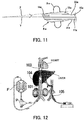
Fig. 12 , while the anticancer drug is continuously administered into the hepatic artery using acatheter 105 of an anticancer drug administration device, twoballoons balloon catheter 101 separately inserted into the blood vessel of the patient occlude upper and lower portions near a branch of the hepatic vein, and the anticancer drug largely administered from the hepatic artery is taken in together with hepatic venous blood as indicated by an arrow from a side hole provided in a part occluded by the both balloons. Thereafter, blood is removed from a blood removal lumen (not illustrated), purified through a pump P and a blood purifier F outside a body, and returned to a blood feeding lumen (not illustrated). Then, the purified and returned blood bypasses a part occluded by theballoons balloon catheter 101 to a heart. - Incidentally, in the PIHP therapy, it is necessary to indwell a distal end balloon in a short curved blood vessel portion between the heart and three hepatic vein holes (a right hepatic vein opening, a middle hepatic vein opening, and a left hepatic vein opening) to completely block a blood flow in the inferior vena cava following a right atrium of the heart using the
balloon catheter 101. When the balloon catheter is inserted into and indwelled in the curved blood vessel, as illustrated inFig. 13 , a central axis of the lumen of the curved blood vessel is shifted from a central axis of theballoon catheter 101 due to an influence of the rigidity of the balloon catheter, and there is a danger that the blood flow directly hits the blood vessel wall as illustrated in the figure and damages the blood vessel wall. In addition, depending on the shape of the blood vessel wall, there is a problem that a contact area of the balloon decreases and the balloon tends to slip due to pressure during blood feeding. Further, there is problem that the balloon may not adhere to the blood vessel wall to generate a gap due to an anatomical individual difference such as a shape of a blood vessel/a degree of curvature/a position of a hepatic vein hole, etc., and a large amount of administered anticancer drug enters circulation blood and is carried to the whole body. In this way, when the balloon catheter is inserted into and indwelled in the curved blood vessel and the blood flow is blocked by the balloon, there are problems of blood vessel wall damage due to a blood flow, balloon slipping due to a decrease in balloon contact area, and incomplete occlusion of the blood vessel (incomplete blockage of a blood flow). - According to investigation by the applicant, a prior art document for solving such problems is not present. However,
JP 5679813 B2 - Patent Literature 1 relates to a tracheostomy tube device and is an invention having a balloon below according to description in claim 1,
Fig. 4 , etc. That is, a balloon 175 disclosed herein is an inflatable balloon surrounding a part of a hollow tube 155. The balloon 175 includes a balloon distal end 180 attached to a distal end 165 of the tube by positioning the distal end of the tube substantially at a center of the balloon and a balloon proximal end 185 located below away from a head of a patient farther than a proximal face P of the device and attached to a bending region 170 of the tube by separating a center of the bending region from substantially the center of the balloon by 8 mm to 10 mm to a front side of the patient. At the time of inflation, the balloon 175 inflates around the distal end of the tube and a proximal end 160 of the tube located below the proximal face of the device to occlude a trachea below a trachea fistula without occluding the trachea fistula (reference numerals are attached for reference). - However, since the balloon 175 is a balloon formed by preliminary shaping in a configuration described above with respect to a catheter body, a wrinkle is formed in a deflated state, and unevenness due to the balloon is generated on a surface of the catheter body, so that adhesion to the surface is not allowed. For this reason, when the catheter having the balloon with unevenness formed on the surface due to the wrinkle is inserted into the blood vessel as the above-mentioned mass administration system, there is concern that an inner wall of the blood vessel may be damaged by unevenness due to the wrinkle of the balloon. Besides, similarly to the conventionally known balloon described above, the problem that the balloon easily slips may not be solved.
- Patent Literature 1:
JP 5679813 B2 Fig. 4 ) - In this regard, an object of the present invention to provide an oblique inflation type balloon catheter in which a balloon may be obliquely inflated to tilt with respect to a main body tube without a central axis of a blood vessel being shifted from a central axis of a catheter body even when the blood vessel is curved, and rarely slips without a contact area with respect to the blood vessel decreasing and a wrinkle being formed on the balloon in a deflated state, and a balloon base by solving the conventional problems described above.
- To solve the above-mentioned problems, the invention described in claim 1 is a balloon catheter in which a balloon is provided at a front end of a tubular catheter body having a predetermined length, wherein a balloon base having a larger diameter than an outer diameter of the catheter body is integrally provided in a cylindrical shape at the front end of the catheter body, the balloon base is formed such that an outer peripheral surface thereof in an axis direction is inclined at a predetermined angle with respect to a central axis of the catheter body, and the balloon is provided on the outer peripheral surface to obliquely inflate with respect to the central axis of the catheter body during inflation.
- The invention described in
claim 2 is a balloon catheter in which a balloon is provided at a front end of a tubular catheter body having a predetermined length, wherein a balloon base is provided at the front end of the catheter body, the balloon base includes a balloon and a base and includes a cylindrical base having a larger diameter than an outer diameter of the catheter body, a lumen having substantially the same diameter as the outer diameter of the catheter body is formed on the base over an entire length with both ends opened, a central axis of the lumen is inclined at a predetermined angle with respect to a central axis of the base concentric with a central axis of the catheter body, an outer peripheral surface in an axis direction is formed in parallel with the central axis of the base, and the balloon is provided on the outer peripheral surface of the parallel base to obliquely inflate with respect to the central axis of the catheter body during inflation. - In the invention described in
claim 3, the lumen of the catheter body is partitioned into a blood removing lumen for removing blood from a blood vessel and a blood feeding lumen for sending blood to the blood vessel, and an opening area of the blood removing lumen is larger than an opening area of the blood feeding lumen inclaim 1 or 2. - In the invention described in
claim 4, a second balloon is provided in the catheter body at a predetermined length behind the balloon, and a side hole for taking blood into the blood removing lumen is provided in the catheter body between the second balloon and the balloon in any one of claims 1 to 3. - In the invention described in
claim 5, the predetermined angle is in a range of 3° to 10° in any one of claims 1 to 4. - The invention described in
claim 6 is a balloon base provided at the front end of the catheter body in the oblique inflation type balloon catheter according to any one of claims 1 to 5, wherein the base includes a cylindrical base having a larger diameter than an outer diameter of the catheter body, a lumen having substantially the same diameter as the outer diameter of the catheter body is formed on the base over an entire length with both ends opened, a central axis of the lumen is inclined at a predetermined angle with respect to a central axis of the base, and an outer peripheral surface in an axis direction is formed in parallel with the central axis of the base. - In the invention described in
claim 7, the predetermined angle is in a range of 3° to 10° inclaim 6. - In the invention described in claim 8, the outer peripheral surface includes an outer peripheral surface of a balloon attachment central portion parallel to the central axis of the base and an outer peripheral surface of both ends curved to have a diameter gradually decreasing from the portion in
claim - In the invention described in claim 9, a communication passage allowing communication between the inside of the balloon and a balloon lumen provided on a peripheral wall of the catheter body is formed in the balloon base in any one of
claims 6 to 8. - The invention is as described above. According to the invention described in claim 1, a balloon base having a larger diameter than an outer diameter of the catheter body is integrally provided in a cylindrical shape at the front end of the catheter body, the balloon base is formed such that an outer peripheral surface thereof in an axis direction is inclined at a predetermined angle with respect to a central axis of the catheter body, and the balloon is provided on the outer peripheral surface to obliquely inflate with respect to the central axis of the catheter body during inflation. In addition, according to the invention described in
claim 2, a balloon base is provided at the front end of the catheter body, the balloon base includes a substantially tubular shaped-base having a larger diameter than an outer diameter of the catheter body, a lumen having substantially the same diameter as the outer diameter of the catheter body is formed on the base over an entire length with both ends opened, a central axis of the lumen is inclined at a predetermined angle with respect to a central axis of the base concentric with a central axis of the catheter body, an outer peripheral surface is formed in parallel with the central axis of the base, and the balloon is provided on the outer peripheral surface of the parallel base to obliquely inflate with respect to the central axis of the catheter body during inflation. Thus, in either case, the balloon may obliquely inflate with respect to the catheter body. For this reason, even in a curved blood vessel, a central axis thereof does not shift from the central axis of the catheter body. Therefore, unlike the conventional one, the central axis of the lumen of the curved blood vessel does not shift from the central axis of the catheter, and the blood flow does not directly hit the blood vessel wall to damage the blood vessel wall due to the rigidity of the catheter. In addition, at the same time, a contact area of the balloon with respect to the blood vessel does not decrease, and adhesion to the outer peripheral surface of the base is allowed since the balloon is not shaped and a wrinkle is not formed even in a balloon deflated state. Therefore, the balloon does not slip due to pressure during blood feeding, and there is an effect that indwelling and fixing may be firmly performed. Further, there are effects that an oblique inflation direction of the balloon may be adjusted by rotating a catheter central axis according to an anatomical individual difference such as a curved shape or a position of a hepatic vein ostium in a short blood vessel lumen between the heart and the liver during use, and the balloon on the distal end side may be appropriately indwelled and fixed. On the other hand, in a conventional balloon incapable of inflating in an oblique direction, a contact position between a balloon and a blood vessel lumen may not be changed even when a central axis of a catheter is rotated. - According to the invention described in
claim 3, since the lumen of the catheter body is partitioned into a blood removing lumen for removing blood from a blood vessel and a blood feeding lumen for sending blood to the blood vessel, and an opening area of the blood removing lumen is larger than an opening area of the blood feeding lumen, it is possible to rapidly, surely, and efficiently remove blood. - According to the invention described in
claim 4, since a second balloon is provided in the catheter body at a predetermined length behind the balloon, and a side hole for taking blood into the blood removing lumen is provided in the catheter body between the second balloon and the balloon, it is possible to effectively withdraw blood between the both balloons from the side hole to the blood removing lumen. - According to the invention described in
claim 5, since the predetermined angle is in a range of 3° to 10°, it is possible to effectively deal with a curved blood vessel of a patient having some individual differences. - According to the invention described in
claim 6, since the base includes a cylindrical base having a larger diameter than an outer diameter of the catheter body, a lumen having substantially the same diameter as the outer diameter of the catheter body is formed on the base over an entire length with both ends opened, a central axis of the lumen is inclined at a predetermined angle with respect to a central axis of the base, and an outer peripheral surface in an axis direction is formed in parallel with the central axis of the base, the balloon attached to the outer peripheral surface with the base interposed therebetween may be inflated to be inclined with respect to the catheter body. - According to the invention described in
claim 7, since the predetermined angle is in a range of 3° to 10°, it is possible to effectively deal with a curved blood vessel of a patient having some individual differences. - According to the invention described in claim 8, since the outer peripheral surface includes an outer peripheral surface of a balloon attachment central portion parallel to the central axis of the base and an outer peripheral surface of both ends curved to have a diameter gradually decreasing from the portion, it is possible to smoothly attach the balloon to the outer peripheral surface of the central portion, and to prevent damage to the blood vessel wall by the outer peripheral surface of the curved both ends.
- According to the invention described in claim 9, since a communication passage for communication between the inside of the balloon and a balloon lumen provided on a peripheral wall of the catheter body is formed in the balloon base, the balloon may be inflated and deflated through the communication passage even when the balloon is attached with the base interposed therebetween.
-
-
Fig. 1 is a front view of an oblique inflation type balloon catheter according to an embodiment of the present invention in which a part of a length of a catheter body is omitted. -
Fig. 2 is an enlarged cross-sectional view of a balloon portion of the same. -
Fig. 3 is an enlarged cross-sectional view taken along III-III line ofFig. 2 . -
Fig. 4 illustrates a balloon base,Fig. 4(A) is a front view,Fig. 4(B) is a rear view,Fig. 4(C) is a left side view, andFig. 4(D) is a right side view. -
Fig. 5 is an enlarged cross-sectional view of the balloon base. -
Fig. 6 is a diagram illustrating a state where a balloon is attached to the balloon base and a step between the balloon and the base is made gentle in a manufacturing process of the balloon catheter of the same. -
Fig. 7 is a diagram illustrating a state where the balloon base to which the balloon is attached is mounted and attached to a main body tube in the manufacturing process of the balloon catheter of the same. -
Fig. 8 is a diagram illustrating a completed state (balloon deflation) of the balloon catheter of the same. -
Fig. 9 is a diagram illustrating a completed state (balloon inflation) of the balloon catheter of the same. -
Fig. 10 is an operation explanatory view illustrating a state where the balloon catheter is inserted into a curved blood vessel of the same. -
Fig. 11 is an enlarged cross-sectional view of a balloon portion corresponding toFig. 2 illustrating a modification. -
Fig. 12 is a schematic explanatory view illustrating an example of a conventionally known mass administration system of anticancer drug. -
Fig. 13 is an operation explanatory view illustrating a state where a conventional balloon catheter is inserted into a curved blood vessel. - Hereinafter, an oblique inflation type balloon catheter according to an embodiment of the present invention will be described with reference to drawings.
- In
Figs. 1 to 3 , reference numeral 1 denotes a balloon catheter made of a material suitable for a living body such as silicone rubber. The balloon catheter 1 mainly includes atubular catheter body 2, balloons 3 and 4, and aballoon base 5. - In the
catheter body 2, alumen 6 having a substantially circular cross section is provided in an axis direction from a front end to a rear end thereof. A front end of thecatheter body 2 is obliquely cut out. Thelumen 6 is partitioned into ablood removing lumen 10 and ablood feeding lumen 11 by an integrally formedpartition wall 7 extending in an axial direction. Theblood removing lumen 10 is for removing blood from a blood vessel in a body, and theblood feeding lumen 11 is for sending blood to the blood vessel in reverse. In this example, an opening area of theblood removing lumen 10 on a surface orthogonal to the axial direction is slightly larger than that of theblood feeding lumen 11. A reason therefor is to carry out blood removal more rapidly, surely and efficiently. A ratio of the opening area of theblood removing lumen 10 to the opening area of theblood feeding lumen 11 is not particularly limited, and is preferably 6 : 4 ratio in terms of ratio. In this example, theblood removing lumen 10 and theblood feeding lumen 11 are partitioned by thepartition wall 7. However, a small-diameter pipe may be concentrically arranged in thelumen 6 without partitioning by thepartition wall 7, and an inside or an outside of the pipe may be used as either theblood removing lumen 10 or theblood feeding lumen 11. - As illustrated in
Fig. 3 , alumen 12 for theballoon 3 at the front and alumen 13 for theballoon 4 at the rear are formed along the axis direction on a wall of thecatheter body 2 near both proximal ends of thepartition wall 7, and communicate with theballoons balloon base 5, respectively. Physiological saline, etc. is injected from a syringe, etc. (not illustrated) into each of thelumens balloons Fig. 2 ,reference numeral 14 denotes a rod-like filling as a padding material which is filled in a front end opening of theblood removing lumen 10 to close the opening. - The
balloon base 5 includes a component independently manufactured separately from thecatheter body 2 and is provided at a front end of thecatheter body 2. Thisballoon base 5 has of an eccentric type single lumen tube type. That is, as specifically illustrated inFigs. 4(A) to 4(D) and Fig. 5 , theballoon base 5 includes a base 15 which has a diameter larger than an outer diameter of thecatheter body 2, is formed in a substantially tubular shape, and has a predetermined length, and alumen 16 having substantially the same diameter as the outer diameter of thecatheter body 2 is formed on the base to open at front and rear ends thereof. - When the base is provided at the front end of the
catheter body 2, thelumen 16 on thebase 15 is provided such that a central axis X thereof is inclined at a predetermined angle θ° with respect to a central axis Y of the base 15 which is concentric with the central axis of thecatheter body 2. This angle of inclination is preferably in a range of 3° to 10°, particularly preferably 4° to 6°, and more particularly preferably 5° in this example. The angle of inclination is not limited to the angle in the range of 3° to 10°, and may be set to an arbitrary angle around the range, particularly in a range of an angle of 16° to 25° for a large angle as necessary since there is an individual difference in degree of curvature of a blood vessel depending on the patient. When thelumen 16 is inclined as described above, a front end opening thereof is located closer to an upper side of thebase 15, and a rear end opening is located closer to a lower side of thebase 15. - At a central portion of the
base 15, twowater passing holes 17 are provided as communication passages for communication between the inside of theballoon 3 and theballoon lumen 12 provided on a peripheral wall of thecatheter body 2. - The
base 15 includes acentral portion 18 which is an outer peripheral surface parallel to the central axis Y of the base 15 concentric with the central axis of thecatheter body 2 as described above and both ends 19 and 20 which are outer peripheral surfaces curved in tapered shapes to have diameters gradually decreasing from the portion. Further, theballoon 3 is provided on the outer peripheral surface of thecentral portion 18 which is parallel. The both ends 19 and 20 have a large degree of curvature on a thicker side and a small degree of curvature on a thinner side. As is clear fromFig. 5 , theballoon base 5 is formed in a point-symmetrical shape centered on a center point P, and a right half and a left half have bilateral symmetry at 180° opposite positions. - Due to the above-described shape, the
balloon base 5 is viewed from the left side in a shape in which the front end opening of thelumen 16 faces upward to face the inside of the lumen as illustrated inFig. 4(C) , and is viewed from the right side in a shape in which the rear end opening of thelumen 16 faces downward to face the inside of the lumen as illustrated inFig. 4(D) . - When dimensions of each component of the
balloon base 5 are described for reference, the total length is 30 mm, the outer diameter is 11.7 mm, the diameter of thelumen 16 is 8 mm, the length of thecentral portion 18 is 17 mm, the length of both ends 19 is 8.6 mm, and the length of both ends 20 is 5.0 mm. - As described above, in the
catheter body 2 between theballoon 4 and theballoon 3 in which theballoon base 5 provided with theballoon 3 is provided at the front end of thecatheter body 2, as illustrated inFig. 2 , a plurality of (three in this example) side holes 22 is provided in the axial direction to communicate with theblood removing lumen 10 and may withdraw blood between both theballoons blood removing lumen 10. For example, a gap between theballoon 3 and theballoon 4 in which the side holes 22 are provided is set to 40 mm to 60 mm. Theballoon 3 is a so-called flat balloon which can flatly adhere to an outer peripheral surface of thecentral portion 18 of theballoon base 5 in a deflated state without forming unevenness. For this reason, a wrinkle as in a conventional case is not formed. - According to the configuration of the
base 5, as is clear fromFigs. 1 and 2 , an outer peripheral surface of thebase 15, to which theballoon 3 is attached, in the axial direction is inclined at the same angle as an inclination angle of thelumen 16, and thus theballoon 3 attached to the front end of thecatheter body 2 through theballoon base 5 obliquely inflates since a line orthogonal to the central axis thereof is inclined at a predetermined angle θ with respect to the central axis of thecatheter body 2 in an inflated state. Theother balloon 4 attached to thecatheter body 2 does not obliquely inflate since a line orthogonal to the central axis thereof is not inclined while being orthogonal to the central axis of thecatheter body 2 in an inflated state. - In
Fig. 1 ,reference numerals main body tube 2. Theconnector 23 communicates with theblood removing lumen 10, and theconnector 24 communicates with theblood feeding lumen 11. A circulation tube having a blood purifier F and a pump P included in the mass administration system of the anticancer drug as a closed circuit described above is connected to theconnector 23 and theconnector 24, blood sent from theblood removing lumen 10 via theconnector 23 is purified by the blood purifier F, and the purified blood is further circulated and sent to theblood feeding lumen 11 via theconnector 24. In addition,reference numerals main body tube 2, a syringe (not illustrated) is connected to these connectingconnectors balloons balloon lumens -
Figs. 6 to 9 are diagrams for description of a method of manufacturing the catheter. This method will be sequentially described as follows. That is, first, theballoon 3 is attached to the individually manufactured balloon base 5 (Fig. 6 ). This attaching operation is performed on the outer peripheral surface of thecentral portion 18 which is a flat cylindrical surface of theballoon base 5, and thus is not difficult and may be smoothly carried out. Thereafter, theballoon base 5 to which theballoon 3 is attached is inserted from the front end of the catheter body 2 (Fig. 7 ), and theballoon base 5 is attached and fixed to thecatheter body 2 when a predetermined attachment position is reached (Fig. 8 ). A dotted line ofFig. 7 indicates an attachment assumed position of thebase 5. When theballoon base 5 is inserted into thecatheter body 2, since thelumen 16 of theballoon base 5 is substantially the same as the outer diameter of thecatheter body 2, an inserted distal end of thecatheter body 2 is bent and fit into thelumen 16 of theballoon base 5 by being adapted thereto. For this reason, theballoon base 5 is provided to be inclined by eccentricity of theballoon base 5 with respect to thecatheter body 2 in a completed state (Fig. 8 ). That is, when theballoon 3 is inflated, theballoon 3 apparently inflates obliquely (Fig. 9 ). The inclination of theballoon 3 can be adjusted by changing an eccentric angle of theballoon base 5. - A method of using the balloon catheter 1 will be described. Basically, the method is similar to the content described in the conventional system for administering a large amount of anticancer drug to the patient with liver cancer illustrated in
Fig. 12 . The balloon catheter 1 is put in a blood vessel of the patient from a front end side thereof, and inserted into a curved blood vessel connecting the superior vena cava and the inferior vena cava close to the heart, so that theballoon 3 is located in the curved blood vessel. Then, when physiological saline is sent via theballoon lumens balloons balloons Fig. 10 ). In this instance, theballoon 3 is in an attachment state described above, and thus obliquely inflates to incline with respect to thecatheter body 2. Meanwhile, when theconnector 23 of the balloon catheter 1 is connected to one end of the circulation tube, and theconnector 24 is connected to the other end of the circulation tube outside the body, the mass administration system of the anticancer drug against liver cancer is constructed in a closed circuit, and the system has a blood purification action in a state where the anticancer drug is continuously administered into the hepatic artery from thecatheter 105 of the anticancer drug administration device as illustrated inFig. 12 . Upon blood purification action, a large amount of anticancer drug administered from thecatheter 105 of the anticancer drug administration device is taken into theblood removing lumen 10 together with the hepatic venous blood from theside hole 22 provided in a occluded part between the twoballoons blood removing lumen 10, purified through the blood purifier F, and returned to theblood feeding lumen 11. The purified and returned blood is sent to the heart from the distal end opening of the balloon catheter 1 by bypassing the part occluded by theballoons - In the operation of the system, the
balloon 3 of the balloon catheter 1 obliquely inflates to incline with respect to thecatheter body 2, and thus a central axis of a blood vessel does not shift from the central axis of thecatheter body 2 even when the blood vessel is curved as illustrated inFig. 10 . For this reason, the blood flow is along the central axis of the blood vessel, and does not directly hit the blood vessel wall as illustrated in the drawing. In other words, unlike the conventional one, the central axis of the lumen of the curved blood vessel does not shift from the central axis of the catheter, and the blood flow does not directly hit the blood vessel wall to damage the blood vessel wall due to the rigidity of the catheter. In addition, even in the curved blood vessel, indwelling and fixing may be surely performed, and a contact area of theballoon 3 with respect to the blood vessel does not decrease. Thus, even in the deflated state of theballoon 3, adhesion to the outer peripheral surface of theballoon base 5 is allowed, and theballoon 3 does not slip due to pressure during blood feeding. - In addition, in the shaped balloon 175 cited as the conventional art, a wrinkle is generated in the balloon in a deflated state, and unevenness of the balloon occurs on the surface of the catheter. Thus, when the catheter of the shaped balloon is inserted into the blood vessel, there is concern that the inner wall of the blood vessel may be damaged due to the wrinkle of the balloon. However, the
balloon 3 of the balloon catheter 1 is a flat balloon that can adhere to the outer peripheral surface of thebase 5 in the deflated state and does not cause unevenness. Thus, even when the catheter is inserted into the lumen, the inner wall of the blood vessel is not damaged. - In this embodiment, the
catheter body 2, theballoon base 5, and theballoons -
Fig. 11 illustrates a modification. The modification is basically different from the embodiment in that a balloon base 5a is formed integrally with a catheter body 2a and is the same as or similar to the embodiment in other respects. For this reason, a description of the same or similar configuration as that in the embodiment will be simplified by attaching an alphabet letter a to the same reference numeral as that in the embodiment. - In more detail, the balloon base 5a is integrally provided in a cylindrical shape having a larger diameter than an outer diameter of the catheter body at a front end of the catheter body 2a. In the balloon base 5a, as is clear from the drawing, an outer peripheral surface in an axis direction, in other words, a central axial formed by the outer peripheral surface is formed to incline at a predetermined angle θ° with respect to a central axis of the catheter body 2a, and a balloon 3a is provided on the outer peripheral surface. The balloon 3a is a flat balloon mentioned above, and obliquely inflates with respect to the central axis of the catheter body 2a in an inflated state. As described above, the predetermined angle θ° is preferably in a range of 3° to 10°. In the figure, Z denotes an axis extending along the outer peripheral surface of the balloon base 5a and intersecting the central axis Y of the catheter body 2a, and Z and Y form the predetermined angle θ°.
- The embodiment is merely a preferable example, and design of details, etc. of the present invention may be appropriately modified and corrected within a range described in claims. For example, the inclination angle of the
lumen 16 of theballoon base 5, the shape of the outer peripheral surface of the both ends 19 and 20 of thebase 15, etc. may be appropriately designed in practice. In addition, theballoon base 5 may not be a separate body as shown in the example of the embodiment, and may be formed integrally with the catheter body 2a as shown in the modification. In addition, even though the embodiment shows an example in which the balloon catheter 1 is used for the mass administration system of the anticancer drug for the liver cancer patient, it goes without saying that the balloon catheter 1 may be used for another purpose. -
- 1
- BALLOON CATHETER
- 2, 2a
- CATHETER BODY
- 3, 3a
- BALLOON
- 4
- BALLOON (SECOND BALLOON)
- 5, 5a
- BALLOON BASE
- 6
- LUMEN
- 7
- PARTITION WALL
- 10, 10a
- BLOOD REMOVING LUMEN
- 11, 11a
- BLOOD FEEDING LUMEN
- 12, 13
- LUMEN FOR BALLOON
- 15, 15a
- BASE
- 16
- LUMEN
- 17
- WATER PASSING HOLE (COMMUNICATION PASSAGE)
- 18
- CENTRAL PORTION
- 19, 20
- BOTH ENDS
- 22, 22a
- SIDE HOLE
- 23, 24
- CONNECTOR
- 25, 26
- CONNECTING CONNECTOR
Claims (9)
- An oblique inflation type balloon catheter in which a balloon is provided at a front end of a tubular catheter body having a predetermined length, wherein
a balloon base having a larger diameter than an outer diameter of the catheter body is integrally provided in a cylindrical shape at the front end of the catheter body, the balloon base is formed such that an outer peripheral surface thereof in an axis direction is inclined at a predetermined angle with respect to a central axis of the catheter body, and the balloon is provided on the outer peripheral surface to obliquely inflate with respect to the central axis of the catheter body during inflation. - An oblique inflation type balloon catheter in which a balloon is provided at a front end of a tubular catheter body having a predetermined length, wherein
a balloon base is provided at the front end of the catheter body, the balloon base includes a balloon and a base and includes a cylindrical base having a larger diameter than an outer diameter of the catheter body, a lumen having substantially the same diameter as the outer diameter of the catheter body is formed on the base over an entire length with both ends opened, a central axis of the lumen is inclined at a predetermined angle with respect to a central axis of the base concentric with a central axis of the catheter body, an outer peripheral surface in an axis direction is formed in parallel with the central axis of the base, and the balloon is provided on the outer peripheral surface of the parallel base to obliquely inflate with respect to the central axis of the catheter body during inflation. - The oblique inflation type balloon catheter according to claim 1 or 2, wherein the lumen of the catheter body is partitioned into a blood removing lumen for removing blood from a blood vessel and a blood feeding lumen for sending blood to the blood vessel, and an opening area of the blood removing lumen is larger than an opening area of the blood feeding lumen.
- The oblique inflation type balloon catheter according to any one of claims 1 to 3, wherein a second balloon is provided in the catheter body at a predetermined length behind the balloon, and a side hole for taking blood into the blood removing lumen is provided in the catheter body between the second balloon and the balloon.
- The oblique inflation type balloon catheter according to any one of claims 1 to 4, wherein the predetermined angle is in a range of 3° to 10°.
- The balloon base provided at the front end of the catheter body in the oblique inflation type balloon catheter according to any one of claims 1 to 5, wherein
the base includes a cylindrical base having a larger diameter than an outer diameter of the catheter body, a lumen having substantially the same diameter as the outer diameter of the catheter body is formed on the base over an entire length with both ends opened, a central axis of the lumen is inclined at a predetermined angle with respect to a central axis of the base, and an outer peripheral surface in an axis direction is formed in parallel with the central axis of the base. - The balloon base according to claim 6, wherein the predetermined angle is in a range of 3° to 10°.
- The balloon base according to claim 6 or 7, wherein the outer peripheral surface includes an outer peripheral surface of a balloon attachment central portion parallel to the central axis of the base and an outer peripheral surface of both ends curved to have a diameter gradually decreasing from the portion.
- The balloon base according to any one of claims 6 to 8, wherein a communication passage allowing communication between the inside of the balloon and a balloon lumen provided on a peripheral wall of the catheter body is formed in the balloon base.
Applications Claiming Priority (1)
| Application Number | Priority Date | Filing Date | Title |
|---|---|---|---|
| PCT/JP2016/060359 WO2017168627A1 (en) | 2016-03-30 | 2016-03-30 | Diagonally expanding balloon catheter and balloon base |
Publications (2)
| Publication Number | Publication Date |
|---|---|
| EP3437689A1 true EP3437689A1 (en) | 2019-02-06 |
| EP3437689A4 EP3437689A4 (en) | 2019-11-27 |
Family
ID=59962766
Family Applications (1)
| Application Number | Title | Priority Date | Filing Date |
|---|---|---|---|
| EP16896846.9A Pending EP3437689A4 (en) | 2016-03-30 | 2016-03-30 | BALLOON CATHETER WITH DIAGONAL EXTENSION AND BALLOON BASE |
Country Status (5)
| Country | Link |
|---|---|
| US (1) | US11617868B2 (en) |
| EP (1) | EP3437689A4 (en) |
| JP (1) | JP6220102B1 (en) |
| CN (1) | CN108738314B (en) |
| WO (1) | WO2017168627A1 (en) |
Families Citing this family (1)
| Publication number | Priority date | Publication date | Assignee | Title |
|---|---|---|---|---|
| CN110743088B (en) * | 2019-11-25 | 2024-11-05 | 无锡市人民医院 | Three-chamber double-balloon blood oxygenation in situ perfusion system |
Family Cites Families (14)
| Publication number | Priority date | Publication date | Assignee | Title |
|---|---|---|---|---|
| US4886059A (en) * | 1988-06-23 | 1989-12-12 | Applied Biometrics, Incorporated | Endotracheal tube with asymmetric balloon |
| US5250029A (en) * | 1991-11-06 | 1993-10-05 | Edward Lin | Zero-residual zero-tip balloon catheter |
| GB9710645D0 (en) | 1997-05-22 | 1997-07-16 | Smiths Industries Plc | Cuffed tube assemblies |
| US6652515B1 (en) * | 1997-07-08 | 2003-11-25 | Atrionix, Inc. | Tissue ablation device assembly and method for electrically isolating a pulmonary vein ostium from an atrial wall |
| AU748342B2 (en) | 1998-03-09 | 2002-06-06 | Avent, Inc. | Tracheal breathing apparatus |
| JP3737057B2 (en) | 2002-03-05 | 2006-01-18 | 新弥 勝山 | Medical catheter |
| JP4119904B2 (en) | 2005-04-28 | 2008-07-16 | 富士システムズ株式会社 | Medical catheter fixture |
| US8460240B2 (en) | 2006-08-07 | 2013-06-11 | W. L. Gore & Associates, Inc. | Inflatable toroidal-shaped balloons |
| US8607795B2 (en) | 2007-09-20 | 2013-12-17 | Kimberly-Clark Worldwide, Inc. | Balloon cuff tracheostomy tube |
| CN201135683Y (en) | 2007-11-07 | 2008-10-22 | 乐普(北京)医疗器械股份有限公司 | A tapered balloon dilatation catheter |
| US8034022B2 (en) * | 2008-04-08 | 2011-10-11 | Cook Medical Technologies Llc | Weeping balloon catheter |
| CN201814973U (en) | 2010-07-27 | 2011-05-04 | 微创医疗器械(上海)有限公司 | Balloon dilating catheter |
| JP2012200573A (en) | 2011-03-28 | 2012-10-22 | Kobe Univ | Two-balloon catheter |
| US9108029B2 (en) * | 2012-05-21 | 2015-08-18 | Nfusion Vascular Systems, Llc | Recovery catheter assembly and method |
-
2016
- 2016-03-30 CN CN201680083231.0A patent/CN108738314B/en active Active
- 2016-03-30 JP JP2017513822A patent/JP6220102B1/en active Active
- 2016-03-30 WO PCT/JP2016/060359 patent/WO2017168627A1/en not_active Ceased
- 2016-03-30 US US16/088,635 patent/US11617868B2/en active Active
- 2016-03-30 EP EP16896846.9A patent/EP3437689A4/en active Pending
Also Published As
| Publication number | Publication date |
|---|---|
| CN108738314A (en) | 2018-11-02 |
| EP3437689A4 (en) | 2019-11-27 |
| JPWO2017168627A1 (en) | 2018-04-05 |
| US11617868B2 (en) | 2023-04-04 |
| US20190366058A1 (en) | 2019-12-05 |
| WO2017168627A1 (en) | 2017-10-05 |
| CN108738314B (en) | 2020-11-10 |
| JP6220102B1 (en) | 2017-10-25 |
Similar Documents
| Publication | Publication Date | Title |
|---|---|---|
| US6132397A (en) | Integral aortic arch infusion clamp catheter | |
| US20220031486A1 (en) | Detachable metal balloon delivery device and method | |
| EP1351738B1 (en) | Drug delivery catheter having a highly compliant balloon with infusion holes | |
| US7273469B1 (en) | Modified needle catheter for directional orientation delivery | |
| US6248121B1 (en) | Blood vessel occlusion device | |
| CN105007973B (en) | Infusion Catheters with Wire Valve Tuning | |
| EP1850902B1 (en) | Infusion catheter | |
| US20130158511A1 (en) | Thrombus removal apparatus and method | |
| US6468243B1 (en) | Balloon catheter | |
| CN106455904A (en) | Interventional sinus endoscope | |
| JPH08508186A (en) | Balloon catheter and device for perfusion with balloon catheter | |
| US20180280666A1 (en) | Medical elongated body | |
| CN104043187A (en) | Controlling Catheter Flow | |
| CN103055409B (en) | Transthoracic aortic cannulation for minimally invasive cardiac surgery | |
| US6068608A (en) | Method of using integral aortic arch infusion clamp | |
| CN107530533A (en) | Conduit of the top with sacculus for continuous nerve block | |
| JP2012200573A (en) | Two-balloon catheter | |
| US11617868B2 (en) | Oblique inflation type balloon catheter and balloon base | |
| US10625045B2 (en) | Expandable intra-venous catheter for a faster intra-venous fluid challenge | |
| JP6275317B2 (en) | Balloon base and oblique inflatable balloon catheter | |
| US10398880B2 (en) | Medical systems, devices, and related methods | |
| US12208193B2 (en) | Cannula and balloon system for extracorporeal membrane oxygenation | |
| WO2022046369A1 (en) | Cannula and balloon system for extracorporeal membrane oxygenation | |
| JPH0938208A (en) | Aortic balloon catheter with suction route for injection of cardiac muscle protecting fluid | |
| JP2012130512A (en) | Guiding catheter |
Legal Events
| Date | Code | Title | Description |
|---|---|---|---|
| STAA | Information on the status of an ep patent application or granted ep patent |
Free format text: STATUS: THE INTERNATIONAL PUBLICATION HAS BEEN MADE |
|
| PUAI | Public reference made under article 153(3) epc to a published international application that has entered the european phase |
Free format text: ORIGINAL CODE: 0009012 |
|
| STAA | Information on the status of an ep patent application or granted ep patent |
Free format text: STATUS: REQUEST FOR EXAMINATION WAS MADE |
|
| 17P | Request for examination filed |
Effective date: 20181026 |
|
| AK | Designated contracting states |
Kind code of ref document: A1 Designated state(s): AL AT BE BG CH CY CZ DE DK EE ES FI FR GB GR HR HU IE IS IT LI LT LU LV MC MK MT NL NO PL PT RO RS SE SI SK SM TR |
|
| AX | Request for extension of the european patent |
Extension state: BA ME |
|
| DAV | Request for validation of the european patent (deleted) | ||
| DAX | Request for extension of the european patent (deleted) | ||
| A4 | Supplementary search report drawn up and despatched |
Effective date: 20191025 |
|
| RIC1 | Information provided on ipc code assigned before grant |
Ipc: A61M 25/10 20130101AFI20191021BHEP |
|
| STAA | Information on the status of an ep patent application or granted ep patent |
Free format text: STATUS: EXAMINATION IS IN PROGRESS |
|
| 17Q | First examination report despatched |
Effective date: 20210525 |
|
| GRAP | Despatch of communication of intention to grant a patent |
Free format text: ORIGINAL CODE: EPIDOSNIGR1 |
|
| STAA | Information on the status of an ep patent application or granted ep patent |
Free format text: STATUS: GRANT OF PATENT IS INTENDED |
|
| INTG | Intention to grant announced |
Effective date: 20250915 |
|
| STAA | Information on the status of an ep patent application or granted ep patent |
Free format text: STATUS: THE APPLICATION IS DEEMED TO BE WITHDRAWN |