EP3437574A1 - Ultrasonic transmission components of ultrasonic surgical instruments and methods of manufacturing the same - Google Patents
Ultrasonic transmission components of ultrasonic surgical instruments and methods of manufacturing the same Download PDFInfo
- Publication number
- EP3437574A1 EP3437574A1 EP18186751.6A EP18186751A EP3437574A1 EP 3437574 A1 EP3437574 A1 EP 3437574A1 EP 18186751 A EP18186751 A EP 18186751A EP 3437574 A1 EP3437574 A1 EP 3437574A1
- Authority
- EP
- European Patent Office
- Prior art keywords
- waveguide
- blade
- body portion
- lumen
- additive manufacturing
- Prior art date
- Legal status (The legal status is an assumption and is not a legal conclusion. Google has not performed a legal analysis and makes no representation as to the accuracy of the status listed.)
- Granted
Links
Images

Classifications
-
- A—HUMAN NECESSITIES
- A61—MEDICAL OR VETERINARY SCIENCE; HYGIENE
- A61B—DIAGNOSIS; SURGERY; IDENTIFICATION
- A61B17/00—Surgical instruments, devices or methods
- A61B17/32—Surgical cutting instruments
- A61B17/320068—Surgical cutting instruments using mechanical vibrations, e.g. ultrasonic
-
- A—HUMAN NECESSITIES
- A61—MEDICAL OR VETERINARY SCIENCE; HYGIENE
- A61B—DIAGNOSIS; SURGERY; IDENTIFICATION
- A61B17/00—Surgical instruments, devices or methods
- A61B17/22—Implements for squeezing-off ulcers or the like on inner organs of the body; Implements for scraping-out cavities of body organs, e.g. bones; for invasive removal or destruction of calculus using mechanical vibrations; for removing obstructions in blood vessels, not otherwise provided for
- A61B17/22004—Implements for squeezing-off ulcers or the like on inner organs of the body; Implements for scraping-out cavities of body organs, e.g. bones; for invasive removal or destruction of calculus using mechanical vibrations; for removing obstructions in blood vessels, not otherwise provided for using mechanical vibrations, e.g. ultrasonic shock waves
- A61B17/22012—Implements for squeezing-off ulcers or the like on inner organs of the body; Implements for scraping-out cavities of body organs, e.g. bones; for invasive removal or destruction of calculus using mechanical vibrations; for removing obstructions in blood vessels, not otherwise provided for using mechanical vibrations, e.g. ultrasonic shock waves in direct contact with, or very close to, the obstruction or concrement
-
- A—HUMAN NECESSITIES
- A61—MEDICAL OR VETERINARY SCIENCE; HYGIENE
- A61B—DIAGNOSIS; SURGERY; IDENTIFICATION
- A61B17/00—Surgical instruments, devices or methods
- A61B17/22—Implements for squeezing-off ulcers or the like on inner organs of the body; Implements for scraping-out cavities of body organs, e.g. bones; for invasive removal or destruction of calculus using mechanical vibrations; for removing obstructions in blood vessels, not otherwise provided for
- A61B17/22004—Implements for squeezing-off ulcers or the like on inner organs of the body; Implements for scraping-out cavities of body organs, e.g. bones; for invasive removal or destruction of calculus using mechanical vibrations; for removing obstructions in blood vessels, not otherwise provided for using mechanical vibrations, e.g. ultrasonic shock waves
- A61B17/22012—Implements for squeezing-off ulcers or the like on inner organs of the body; Implements for scraping-out cavities of body organs, e.g. bones; for invasive removal or destruction of calculus using mechanical vibrations; for removing obstructions in blood vessels, not otherwise provided for using mechanical vibrations, e.g. ultrasonic shock waves in direct contact with, or very close to, the obstruction or concrement
- A61B17/2202—Implements for squeezing-off ulcers or the like on inner organs of the body; Implements for scraping-out cavities of body organs, e.g. bones; for invasive removal or destruction of calculus using mechanical vibrations; for removing obstructions in blood vessels, not otherwise provided for using mechanical vibrations, e.g. ultrasonic shock waves in direct contact with, or very close to, the obstruction or concrement the ultrasound transducer being inside patient's body at the distal end of the catheter
-
- A—HUMAN NECESSITIES
- A61—MEDICAL OR VETERINARY SCIENCE; HYGIENE
- A61B—DIAGNOSIS; SURGERY; IDENTIFICATION
- A61B17/00—Surgical instruments, devices or methods
- A61B17/32—Surgical cutting instruments
- A61B17/320068—Surgical cutting instruments using mechanical vibrations, e.g. ultrasonic
- A61B17/320092—Surgical cutting instruments using mechanical vibrations, e.g. ultrasonic with additional movable means for clamping or cutting tissue, e.g. with a pivoting jaw
-
- B—PERFORMING OPERATIONS; TRANSPORTING
- B33—ADDITIVE MANUFACTURING TECHNOLOGY
- B33Y—ADDITIVE MANUFACTURING, i.e. MANUFACTURING OF THREE-DIMENSIONAL [3D] OBJECTS BY ADDITIVE DEPOSITION, ADDITIVE AGGLOMERATION OR ADDITIVE LAYERING, e.g. BY 3D PRINTING, STEREOLITHOGRAPHY OR SELECTIVE LASER SINTERING
- B33Y10/00—Processes of additive manufacturing
-
- B—PERFORMING OPERATIONS; TRANSPORTING
- B33—ADDITIVE MANUFACTURING TECHNOLOGY
- B33Y—ADDITIVE MANUFACTURING, i.e. MANUFACTURING OF THREE-DIMENSIONAL [3D] OBJECTS BY ADDITIVE DEPOSITION, ADDITIVE AGGLOMERATION OR ADDITIVE LAYERING, e.g. BY 3D PRINTING, STEREOLITHOGRAPHY OR SELECTIVE LASER SINTERING
- B33Y80/00—Products made by additive manufacturing
-
- A—HUMAN NECESSITIES
- A61—MEDICAL OR VETERINARY SCIENCE; HYGIENE
- A61B—DIAGNOSIS; SURGERY; IDENTIFICATION
- A61B17/00—Surgical instruments, devices or methods
- A61B17/00234—Surgical instruments, devices or methods for minimally invasive surgery
- A61B2017/00349—Needle-like instruments having hook or barb-like gripping means, e.g. for grasping suture or tissue
-
- A—HUMAN NECESSITIES
- A61—MEDICAL OR VETERINARY SCIENCE; HYGIENE
- A61B—DIAGNOSIS; SURGERY; IDENTIFICATION
- A61B17/00—Surgical instruments, devices or methods
- A61B2017/00526—Methods of manufacturing
-
- A—HUMAN NECESSITIES
- A61—MEDICAL OR VETERINARY SCIENCE; HYGIENE
- A61B—DIAGNOSIS; SURGERY; IDENTIFICATION
- A61B17/00—Surgical instruments, devices or methods
- A61B2017/00681—Aspects not otherwise provided for
- A61B2017/00734—Aspects not otherwise provided for battery operated
-
- A—HUMAN NECESSITIES
- A61—MEDICAL OR VETERINARY SCIENCE; HYGIENE
- A61B—DIAGNOSIS; SURGERY; IDENTIFICATION
- A61B17/00—Surgical instruments, devices or methods
- A61B17/22—Implements for squeezing-off ulcers or the like on inner organs of the body; Implements for scraping-out cavities of body organs, e.g. bones; for invasive removal or destruction of calculus using mechanical vibrations; for removing obstructions in blood vessels, not otherwise provided for
- A61B17/22004—Implements for squeezing-off ulcers or the like on inner organs of the body; Implements for scraping-out cavities of body organs, e.g. bones; for invasive removal or destruction of calculus using mechanical vibrations; for removing obstructions in blood vessels, not otherwise provided for using mechanical vibrations, e.g. ultrasonic shock waves
- A61B17/22012—Implements for squeezing-off ulcers or the like on inner organs of the body; Implements for scraping-out cavities of body organs, e.g. bones; for invasive removal or destruction of calculus using mechanical vibrations; for removing obstructions in blood vessels, not otherwise provided for using mechanical vibrations, e.g. ultrasonic shock waves in direct contact with, or very close to, the obstruction or concrement
- A61B2017/22014—Implements for squeezing-off ulcers or the like on inner organs of the body; Implements for scraping-out cavities of body organs, e.g. bones; for invasive removal or destruction of calculus using mechanical vibrations; for removing obstructions in blood vessels, not otherwise provided for using mechanical vibrations, e.g. ultrasonic shock waves in direct contact with, or very close to, the obstruction or concrement the ultrasound transducer being outside patient's body; with an ultrasound transmission member; with a wave guide; with a vibrated guide wire
-
- A—HUMAN NECESSITIES
- A61—MEDICAL OR VETERINARY SCIENCE; HYGIENE
- A61B—DIAGNOSIS; SURGERY; IDENTIFICATION
- A61B17/00—Surgical instruments, devices or methods
- A61B17/28—Surgical forceps
- A61B17/29—Forceps for use in minimally invasive surgery
- A61B2017/2926—Details of heads or jaws
- A61B2017/2945—Curved jaws
-
- A—HUMAN NECESSITIES
- A61—MEDICAL OR VETERINARY SCIENCE; HYGIENE
- A61B—DIAGNOSIS; SURGERY; IDENTIFICATION
- A61B17/00—Surgical instruments, devices or methods
- A61B17/32—Surgical cutting instruments
- A61B17/320068—Surgical cutting instruments using mechanical vibrations, e.g. ultrasonic
- A61B2017/320069—Surgical cutting instruments using mechanical vibrations, e.g. ultrasonic for ablating tissue
-
- A—HUMAN NECESSITIES
- A61—MEDICAL OR VETERINARY SCIENCE; HYGIENE
- A61B—DIAGNOSIS; SURGERY; IDENTIFICATION
- A61B17/00—Surgical instruments, devices or methods
- A61B17/32—Surgical cutting instruments
- A61B17/320068—Surgical cutting instruments using mechanical vibrations, e.g. ultrasonic
- A61B2017/320072—Working tips with special features, e.g. extending parts
- A61B2017/320073—Working tips with special features, e.g. extending parts probe
-
- A—HUMAN NECESSITIES
- A61—MEDICAL OR VETERINARY SCIENCE; HYGIENE
- A61B—DIAGNOSIS; SURGERY; IDENTIFICATION
- A61B17/00—Surgical instruments, devices or methods
- A61B17/32—Surgical cutting instruments
- A61B17/320068—Surgical cutting instruments using mechanical vibrations, e.g. ultrasonic
- A61B2017/320072—Working tips with special features, e.g. extending parts
- A61B2017/320074—Working tips with special features, e.g. extending parts blade
-
- A—HUMAN NECESSITIES
- A61—MEDICAL OR VETERINARY SCIENCE; HYGIENE
- A61B—DIAGNOSIS; SURGERY; IDENTIFICATION
- A61B17/00—Surgical instruments, devices or methods
- A61B17/32—Surgical cutting instruments
- A61B17/320068—Surgical cutting instruments using mechanical vibrations, e.g. ultrasonic
- A61B17/320092—Surgical cutting instruments using mechanical vibrations, e.g. ultrasonic with additional movable means for clamping or cutting tissue, e.g. with a pivoting jaw
- A61B2017/320094—Surgical cutting instruments using mechanical vibrations, e.g. ultrasonic with additional movable means for clamping or cutting tissue, e.g. with a pivoting jaw additional movable means performing clamping operation
-
- A—HUMAN NECESSITIES
- A61—MEDICAL OR VETERINARY SCIENCE; HYGIENE
- A61B—DIAGNOSIS; SURGERY; IDENTIFICATION
- A61B18/00—Surgical instruments, devices or methods for transferring non-mechanical forms of energy to or from the body
- A61B2018/00005—Cooling or heating of the probe or tissue immediately surrounding the probe
- A61B2018/00011—Cooling or heating of the probe or tissue immediately surrounding the probe with fluids
- A61B2018/00023—Cooling or heating of the probe or tissue immediately surrounding the probe with fluids closed, i.e. without wound contact by the fluid
-
- A—HUMAN NECESSITIES
- A61—MEDICAL OR VETERINARY SCIENCE; HYGIENE
- A61B—DIAGNOSIS; SURGERY; IDENTIFICATION
- A61B2560/00—Constructional details of operational features of apparatus; Accessories for medical measuring apparatus
- A61B2560/02—Operational features
- A61B2560/0204—Operational features of power management
- A61B2560/0214—Operational features of power management of power generation or supply
Definitions
- the present disclosure relates to ultrasonic surgical instruments and, more specifically, to ultrasonic transmission components, e.g., waveguides, end effectors, etc., of ultrasonic surgical instruments and methods of manufacturing ultrasonic transmission components of ultrasonic surgical instruments.
- ultrasonic transmission components e.g., waveguides, end effectors, etc.
- Energy-based tissue treatment is well known in the art.
- Various types of energy e.g., electrical, ultrasonic, microwave, cryogenic, thermal, laser, etc.
- Ultrasonic energy for example, may be delivered to tissue to treat, e.g., coagulate and/or cut, tissue.
- Ultrasonic surgical instruments typically include a waveguide having a transducer coupled thereto at a proximal end of the waveguide and an end effector disposed at a distal end of the waveguide.
- the waveguide transmits ultrasonic energy produced by the transducer to the end effector for treating tissue at the end effector.
- the end effector may include a blade, hook, ball, shears, etc., and/or other features such as one or more jaws for grasping or manipulating tissue.
- distal refers to the portion that is being described which is further from a user
- proximal refers to the portion that is being described which is closer to a user
- an ultrasonic transmission component of an ultrasonic surgical instrument including forming, via additive manufacturing, a waveguide.
- the waveguide is formed to include a body portion and a curved blade extending distally from the body portion and to define a lumen extending through a portion or the entirety of the body portion and a portion or the entirety of the curved blade.
- the waveguide is formed via Direct Metal Laser Sintering.
- the waveguide is formed via Selective Laser Sintering or other additive manufacturing technique.
- the method further includes modeling the waveguide using a computer-aided design program and using the modeled waveguide to form the waveguide via additive manufacturing.
- the lumen extends a majority of a length of the body potion and a majority of a length of the curved blade.
- the lumen may additionally or alternatively define a closed distal end portion.
- the waveguide is formed from titanium.
- the body portion and/or the curved blade are formed to include a varied density. Additionally or alternatively, at least a portion of the body portion and/or at least a portion of the curved blade are formed to include a lattice structure.
- the method further includes inserting an inner tube at least partially into the lumen.
- Another method of manufacturing an ultrasonic transmission component of an ultrasonic surgical instrument includes forming, via additive manufacturing, a waveguide including a body portion and a blade extending distally from the body portion.
- the body portion and/or the blade defines a varied density.
- the waveguide is formed via Direct Metal Laser Sintering.
- the waveguide is formed via Selective Laser Sintering or other additive manufacturing technique.
- the method further includes modeling the waveguide using a computer-aided design program and using the modeled waveguide to form the waveguide via additive manufacturing.
- the waveguide is further formed to define a lumen extending through a portion of the body portion and a portion of the blade.
- the lumen in aspects, may extend a majority of a length of the body potion and/or a majority of a length of the blade.
- the method may further include inserting an inner tube at least partially into the lumen.
- the waveguide is formed from titanium.
- At least a portion of the body portion and/or at least a portion of the blade is formed to include a lattice structure.
- the blade is curved.
- ultrasonic surgical instrument 10 FIG. 1
- the present disclosure provides ultrasonic transmission components of ultrasonic surgical instruments and methods of manufacturing the same. Although detailed below with respect to ultrasonic surgical instrument 10 ( FIG. 1 ), the aspects and features of the present disclosure are equally applicable for use with other ultrasonic surgical instruments. For the purposes herein, ultrasonic surgical instrument 10 ( FIG. 1 ) is general described.
- Ultrasonic surgical instrument 10 generally includes a handle assembly 100, an elongated assembly 200 extending distally from handle assembly 100, an ultrasonic transducer and generator assembly ("TAG") 300 configured for releasable engagement with handle assembly 100, a battery assembly 400 configured for releasable receipt within handle assembly 100, and a cooling system 500 operably disposed within and extending through handle assembly 100 and elongated assembly 200.
- TAG ultrasonic transducer and generator assembly
- ultrasonic surgical instrument 10 is configured as a cordless, hand-held device.
- the present disclosure is equally applicable for use with corded ultrasonic surgical instruments configured to connect to a remote generator.
- Handle assembly 100 includes a housing 110 defining a body portion 112 configured to enable releasable mounting of TAG 300 thereon and a fixed handle portion 114 depending from body portion 112.
- Fixed handle portion 114 defines a battery compartment 116 including a door 118 configured to enable releasable receipt and enclosure of battery assembly 400 within fixed handle portion 114.
- Handle assembly 100 further includes an activation button 120 operably positioned to electrically couple between TAG 300 and battery assembly 400 when TAG 300 is mounted on body portion 112 of housing 110 and battery assembly 400 is enclosed within compartment 116 of fixed handle portion 114 of housing 110 to enable selective energization of ultrasonic surgical instrument 10, as detailed below.
- a clamp trigger 130 extends from housing 110 of handle assembly 100 adjacent fixed handle portion 114 of housing 110.
- Clamp trigger 130 includes a drive portion (not shown) extending into body portion 112 of housing 110 and operably coupled to a drive assembly (not shown) to enable actuation of ultrasonic surgical instrument 10 in response to actuation of clamp trigger 130 relative to fixed handle portion 114 of housing 110, as also detailed below.
- elongated assembly 200 of ultrasonic surgical instrument 10 includes a waveguide 210 which extends from housing 110 to an end effector 220 disposed at the distal end portion of elongated assembly 200.
- Elongated assembly 200 further includes an outer tube 230 and an inner tube (not shown).
- Waveguide 210 includes a body portion 212 that extends through housing 110 and outer tube 230 and a distal end portion that extends distally from outer tube 230 and defines blade 222 of end effector 220.
- Waveguide 210 may be formed from titanium, a titanium alloy, or other suitable material(s).
- the proximal end portion of body portion 212 of waveguide 210 includes features, e.g., threading 214, configured to enable operable engagement thereof with TAG 300, e.g., with a female threaded receiver (not shown) of the transducer of TAG 300.
- Outer tube 230 is slidably disposed about waveguide 210 and extends between housing 110 and end effector 220.
- a rotating assembly 240 is rotatably mounted on housing 110 and operably coupled to elongated assembly 200 so as to enable rotation of elongated assembly 200 and, thus, end effector 220 relative to housing 110 upon rotation of rotation wheel 242 of rotating assembly 240 relative to housing 110.
- End effector 220 is disposed at a distal end portion of elongated assembly 200 and includes blade 222 of waveguide 210 and a jaw member 224.
- Jaw member 224 is pivotable relative to blade 222 between an open position, wherein jaw member 224 is spaced-apart from blade 222, and a closed position, wherein jaw member 224 is approximated relative to blade 222 in juxtaposed alignment therewith for clamping tissue therebetween.
- Jaw member 224 is operably coupled to the distal end portion of outer tube 230 and a proximal end portion of outer tube 230, in turn, is operably coupled to clamp trigger 130 by way of the drive assembly (not shown) such that jaw member 224 is movable between the open position and the closed position in response to actuation of clamp trigger 130 relative to fixed handle portion 114 of housing 110 of handle assembly 100.
- Blade 222 is configured to serve as an active or oscillating ultrasonic member that is selectively activatable to ultrasonically treat tissue grasped between blade 222 and jaw member 224. As shown in FIG. 2 , blade 222 is formed to define a curved configuration, although straight configurations are also contemplated. Blade 222 may be curved in any direction relative to jaw member 224, for example, such that the distal tip of blade 222 is curved towards jaw member 224, away from jaw member 224, or laterally (in either direction) relative to jaw member 224. Further, blade 222 may be formed to include multiple curves in similar directions, multiple curves in different directions within a single plane, and/or multiple curves in different directions in different planes.
- Blade 222 may additionally or alternatively be formed to include a tapered configuration, various different cross-sectional configurations along its length, cut-outs, indents, edges, protrusions, straight surfaces, curved surfaces, angled surfaces, wide edges, narrow edges, and/or other features. Blade 222 may also be formed to include a varying density and/or a lattice structure to reinforce portions thereof, provide increased flexibility in portions thereof, increase or decrease displacement of portions thereof, increase or decrease operating temperature of portions thereof, etc. Put more generally, blade 222 may be formed to include any suitable configuration and/or features to facilitate use in a particular fashion(s), achieve a particular tissue effect(s), generate particular resonant frequency(s), facilitate a particular heating and/or cooling profile, etc.
- Body portion 212 of waveguide 210 may likewise be formed to include various features. As noted above, body portion 212 of waveguide 210 includes threading 214 to enable threaded engagement of waveguide 210 with TAG 300 ( FIG. 1 ). Body portion 212 of waveguide 210 may further include a torque block 216 formed thereon towards a proximal end portion thereof to facilitate coupling of waveguide 210 with rotating assembly 240. Body portion 212 of waveguide 210 may additionally or alternatively include a tapered configuration, various different cross-sectional configurations along its length, flats, various different diameters, coupling features to facilitate coupling of waveguide 210 to other components of ultrasonic surgical instrument 10 ( FIG. 1 ), and/or other features.
- Body portion 212 of waveguide 210 may also be formed to include a varying density and/or a lattice structure to reinforce portions thereof, provide increased flexibility in portions thereof, etc.
- body portion 212 of waveguide 210 like blade 222, may be formed to include any suitable configuration and/or features to facilitate use in a particular fashion(s), achieve a particular tissue effect(s), generate particular resonant frequency(s), facilitate a particular heating and/or cooling profile, etc.
- Body portion 212 of waveguide 210 and blade 222 may be monolithically formed, e.g., from a titanium alloy, or may be separately formed and then connected to one another.
- body portion 212 of waveguide 210 and/or blade 222 may be formed to include a longitudinally-extending lumen 218 defined through at least a portion thereof.
- Lumen 218 may define a constant diameter, varying diameter, or other suitable configuration, and may follow the curvature of blade 222 or define a different curvature, for example.
- Lumen 218 may define a closed distal end portion that is proximally-spaced from the distal end portion of blade 222, or may include an open distal end portion.
- Lumen 218 may include an open proximal end portion (not shown) at the proximal end portion of waveguide 210.
- lumen 218 may be defined through a side surface of blade 222 or body portion 212 of waveguide 210 at any suitable position along the length thereof.
- lumen 218 enables flow and/or circulation of cooling fluid through waveguide 210 and/or blade 222 to cool waveguide 210 and blade 222 before, during, and/or after use.
- waveguide 210 and/or blade 222 may additionally be formed to include an inner tube 219 extending at least partially through longitudinally-extending lumen 218.
- inner tube 219 may be inserted into lumen 218 after formation of waveguide 210 and blade 222.
- inner tube 219 may define a constant diameter, varying diameter, or other suitable configuration.
- Inner tube 219 may define an open distal end portion and/or may include apertures, slots, etc. (not shown) defined therethrough at one or more locations along a length thereof.
- inner tube 219 cooperates with lumen 218 to enable circulation of cooling fluid through waveguide 210 and/or blade 222 to cool waveguide 210 and blade 222 before, during, and/or after use.
- TAG 300 is configured to convert electrical energy provided by battery assembly 400 into mechanical energy that is transmitted along waveguide 210 to blade 222. More specifically, TAG 300 is configured to convert the electrical energy provided by battery assembly 400 into a high voltage alternating current (AC) waveform that drives the transducer (not shown) of TAG 300.
- Activation button 120 of handle assembly 100 is electrically coupled between battery assembly 400 and TAG 300. Activation button 120 is selectively activatable in a first position and a second position to supply electrical energy from battery assembly 400 to TAG 300 for operating ultrasonic surgical instrument 10 in a low-power mode of operation and a high-power mode of operation, respectively.
- TAG 300 and battery assembly 400 are each removable from handle assembly 100 (together or separately) to facilitate disposal of handle assembly 100 after a single use or to enable sterilization of handle assembly 100 for subsequent use.
- TAG 300 may be configured to withstand sterilization such that TAG 300 may be sterilized for repeated use.
- Battery assembly 400 is configured to be aseptically transferred and retained within compartment 116 of fixed handle portion 114 of housing 110 of handle assembly 100 such that battery assembly 400 may be repeatedly used without requiring sterilization thereof, although other configurations of TAG 300 and battery assembly 400 are also contemplated.
- cooling system 500 includes a cooling module 510, a cooling activation button 520, and inflow and return conduits 530, 540, respectively.
- Cooling module 510 includes a fluid reservoir 512 and one or more fluid pumps 514 and is disposed within housing 110 of handle assembly 100 or, alternatively, incorporated into TAG 300 or battery assembly 400.
- Cooling activation button 520 is disposed on housing 110 and operably coupled to cooling module 510 to enable the selective actuation thereof to initiate cooling, although cooling may alternatively or additionally be automatically controlled.
- Inflow and return conduits 530, 540 are operably coupled between cooling module 510 and lumen 218 (and inner tube 219 (if so provided)) of waveguide 210 and/or blade 222 to supply and retrieve cooling fluid thereto and therefrom, respectively. More specifically, cooling fluid may be pumped from cooling module 510 through inflow conduit 530 into inner tube 219 to exit inner tube 219 near the distal end portion of lumen 218 and may return to cooling module 510 via the annular space of lumen 218 surrounding inner tube 219 and, eventually, return conduit 540. Other configurations are also contemplated.
- the present disclosure provides methods for manufacturing body portion 212 of waveguide 210, blade 222, or waveguide 210 in its entirety (including body portion 212 and blade 222) to include any or all of the above-noted features, as traditional manufacturing techniques are ineffective at creating such feature or, if possible to create such features, are technically challenging and/or expensive.
- Such features include, for example and without limitation: a lumen 218 extending the majority (or the entirety) of the length of body portion 212 and into blade 222; a lumen 218 extending through a curved blade 222; a body portion 212 of waveguide 210 and/or blade 222 formed of varying density and/or including a lattice structure; and a body portion 212 of waveguide 210 and/or blade 222 including various different external features.
- body portion 212 of waveguide 210 and/or blade 222 are manufactured using an additive manufacturing technique (also known as 3D printing). More specifically, body portion 212 of waveguide 210 and/or blade 222 may be manufactured via Direct Metal Laser Sintering (DMLS) or Selective Laser Sintering (SLS). As noted above, body portion 212 of waveguide 210 and/or blade 222 may be manufactured from a metal, e.g., titanium, a titanium alloy, or other suitable metal, or other material.
- DMLS Direct Metal Laser Sintering
- SLS Selective Laser Sintering
- Using an additive manufacturing technique allows the body portion 212 of waveguide 210 and/or blade 222, including the particular features and/or configuration desired, to be modeled using a Computer Aided Design (CAD) program, from which the body portion 212 of waveguide 210 and/or blade 222 is built in layer-by-later fashion via the additive manufacturing technique, e.g., Direct Metal Laser Sintering (DMLS) or Selective Laser Sintering (SLS).
- Tube 219 if provided, may be formed within lumen 218 of body portion 212 of waveguide 210 and/or blade 222 as part of the additive manufacturing technique or may be inserted into lumen 218 and subsequent to manufacture of body portion 212 of waveguide 210 and/or blade 222.
Landscapes
- Health & Medical Sciences (AREA)
- Engineering & Computer Science (AREA)
- Surgery (AREA)
- Life Sciences & Earth Sciences (AREA)
- Medical Informatics (AREA)
- General Health & Medical Sciences (AREA)
- Veterinary Medicine (AREA)
- Public Health (AREA)
- Biomedical Technology (AREA)
- Heart & Thoracic Surgery (AREA)
- Mechanical Engineering (AREA)
- Molecular Biology (AREA)
- Animal Behavior & Ethology (AREA)
- Nuclear Medicine, Radiotherapy & Molecular Imaging (AREA)
- Dentistry (AREA)
- Chemical & Material Sciences (AREA)
- Manufacturing & Machinery (AREA)
- Materials Engineering (AREA)
- Orthopedic Medicine & Surgery (AREA)
- Vascular Medicine (AREA)
- Surgical Instruments (AREA)
Abstract
Description
- The present disclosure relates to ultrasonic surgical instruments and, more specifically, to ultrasonic transmission components, e.g., waveguides, end effectors, etc., of ultrasonic surgical instruments and methods of manufacturing ultrasonic transmission components of ultrasonic surgical instruments.
- Energy-based tissue treatment is well known in the art. Various types of energy (e.g., electrical, ultrasonic, microwave, cryogenic, thermal, laser, etc.) are applied to tissue to achieve a desired result. Ultrasonic energy, for example, may be delivered to tissue to treat, e.g., coagulate and/or cut, tissue.
- Ultrasonic surgical instruments, for example, typically include a waveguide having a transducer coupled thereto at a proximal end of the waveguide and an end effector disposed at a distal end of the waveguide. The waveguide transmits ultrasonic energy produced by the transducer to the end effector for treating tissue at the end effector. The end effector may include a blade, hook, ball, shears, etc., and/or other features such as one or more jaws for grasping or manipulating tissue.
- As used herein, the term "distal" refers to the portion that is being described which is further from a user, while the term "proximal" refers to the portion that is being described which is closer to a user. Further, to the extent consistent, any of the aspects described herein may be used in conjunction with any or all of the other aspects described herein.
- Provided in accordance with aspects of the present disclosure is a method of manufacturing an ultrasonic transmission component of an ultrasonic surgical instrument including forming, via additive manufacturing, a waveguide. The waveguide is formed to include a body portion and a curved blade extending distally from the body portion and to define a lumen extending through a portion or the entirety of the body portion and a portion or the entirety of the curved blade.
- In aspects of the present disclosure, the waveguide is formed via Direct Metal Laser Sintering. Alternatively, the waveguide is formed via Selective Laser Sintering or other additive manufacturing technique.
- In aspects of the present disclosure, the method further includes modeling the waveguide using a computer-aided design program and using the modeled waveguide to form the waveguide via additive manufacturing.
- In aspects of the present disclosure, the lumen extends a majority of a length of the body potion and a majority of a length of the curved blade. The lumen may additionally or alternatively define a closed distal end portion.
- In aspects of the present disclosure, the waveguide is formed from titanium.
- In aspects of the present disclosure, the body portion and/or the curved blade are formed to include a varied density. Additionally or alternatively, at least a portion of the body portion and/or at least a portion of the curved blade are formed to include a lattice structure.
- In aspects of the present disclosure, the method further includes inserting an inner tube at least partially into the lumen.
- Another method of manufacturing an ultrasonic transmission component of an ultrasonic surgical instrument provided in accordance with aspects of the present disclosure includes forming, via additive manufacturing, a waveguide including a body portion and a blade extending distally from the body portion. The body portion and/or the blade defines a varied density.
- In aspects of the present disclosure, the waveguide is formed via Direct Metal Laser Sintering. Alternatively, the waveguide is formed via Selective Laser Sintering or other additive manufacturing technique.
- In aspects of the present disclosure, the method further includes modeling the waveguide using a computer-aided design program and using the modeled waveguide to form the waveguide via additive manufacturing.
- In aspects of the present disclosure, the waveguide is further formed to define a lumen extending through a portion of the body portion and a portion of the blade. The lumen, in aspects, may extend a majority of a length of the body potion and/or a majority of a length of the blade. The method may further include inserting an inner tube at least partially into the lumen.
- In aspects of the present disclosure, the waveguide is formed from titanium.
- In aspects of the present disclosure, at least a portion of the body portion and/or at least a portion of the blade is formed to include a lattice structure.
- In aspects of the present disclosure, the blade is curved.
- Various aspects and features of the present disclosure are described hereinbelow with reference to the drawings wherein like numerals designate identical or corresponding elements in each of the several views:
-
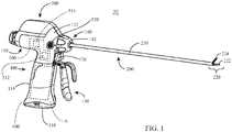
FIG. 1 is a perspective view of an ultrasonic surgical instrument provided in accordance with the present disclosure; -
FIG. 2 is a perspective view of a waveguide of the ultrasonic surgical instrument ofFIG. 1 ; -
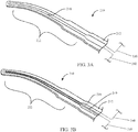
FIG. 3A is a longitudinal, cross-sectional view of a distal end portion of the waveguide ofFIG. 2 including a lumen defined therethrough; and -
FIG. 3B is a longitudinal, cross-sectional view of the distal end portion of the waveguide ofFIG. 2 including an inner tube extending through the lumen. - The present disclosure provides ultrasonic transmission components of ultrasonic surgical instruments and methods of manufacturing the same. Although detailed below with respect to ultrasonic surgical instrument 10 (
FIG. 1 ), the aspects and features of the present disclosure are equally applicable for use with other ultrasonic surgical instruments. For the purposes herein, ultrasonic surgical instrument 10 (FIG. 1 ) is general described. - Referring generally to
FIG. 1 , an ultrasonic surgical instrument provided in accordance with the aspects and features of the present disclosure is shown generally identified byreference numeral 10. Ultrasonicsurgical instrument 10 generally includes ahandle assembly 100, anelongated assembly 200 extending distally fromhandle assembly 100, an ultrasonic transducer and generator assembly ("TAG") 300 configured for releasable engagement withhandle assembly 100, abattery assembly 400 configured for releasable receipt withinhandle assembly 100, and acooling system 500 operably disposed within and extending throughhandle assembly 100 andelongated assembly 200. Thus, ultrasonicsurgical instrument 10 is configured as a cordless, hand-held device. However, the present disclosure is equally applicable for use with corded ultrasonic surgical instruments configured to connect to a remote generator. -
Handle assembly 100 includes ahousing 110 defining abody portion 112 configured to enable releasable mounting ofTAG 300 thereon and afixed handle portion 114 depending frombody portion 112. Fixedhandle portion 114 defines abattery compartment 116 including adoor 118 configured to enable releasable receipt and enclosure ofbattery assembly 400 withinfixed handle portion 114.Handle assembly 100 further includes anactivation button 120 operably positioned to electrically couple betweenTAG 300 andbattery assembly 400 when TAG 300 is mounted onbody portion 112 ofhousing 110 andbattery assembly 400 is enclosed withincompartment 116 offixed handle portion 114 ofhousing 110 to enable selective energization of ultrasonicsurgical instrument 10, as detailed below. - A
clamp trigger 130 extends fromhousing 110 ofhandle assembly 100 adjacentfixed handle portion 114 ofhousing 110.Clamp trigger 130 includes a drive portion (not shown) extending intobody portion 112 ofhousing 110 and operably coupled to a drive assembly (not shown) to enable actuation of ultrasonicsurgical instrument 10 in response to actuation ofclamp trigger 130 relative tofixed handle portion 114 ofhousing 110, as also detailed below. - With additional reference to
FIG. 2 ,elongated assembly 200 of ultrasonicsurgical instrument 10 includes awaveguide 210 which extends fromhousing 110 to anend effector 220 disposed at the distal end portion ofelongated assembly 200. Elongatedassembly 200 further includes anouter tube 230 and an inner tube (not shown). Waveguide 210 includes abody portion 212 that extends throughhousing 110 andouter tube 230 and a distal end portion that extends distally fromouter tube 230 and definesblade 222 ofend effector 220.Waveguide 210 may be formed from titanium, a titanium alloy, or other suitable material(s). The proximal end portion ofbody portion 212 ofwaveguide 210 includes features, e.g.,threading 214, configured to enable operable engagement thereof with TAG 300, e.g., with a female threaded receiver (not shown) of the transducer ofTAG 300. -
Outer tube 230 is slidably disposed aboutwaveguide 210 and extends betweenhousing 110 andend effector 220. A rotating assembly 240 is rotatably mounted onhousing 110 and operably coupled toelongated assembly 200 so as to enable rotation ofelongated assembly 200 and, thus,end effector 220 relative tohousing 110 upon rotation of rotation wheel 242 of rotating assembly 240 relative tohousing 110. -
End effector 220 is disposed at a distal end portion ofelongated assembly 200 and includesblade 222 ofwaveguide 210 and ajaw member 224. Jawmember 224 is pivotable relative toblade 222 between an open position, whereinjaw member 224 is spaced-apart fromblade 222, and a closed position, whereinjaw member 224 is approximated relative toblade 222 in juxtaposed alignment therewith for clamping tissue therebetween. Jawmember 224 is operably coupled to the distal end portion ofouter tube 230 and a proximal end portion ofouter tube 230, in turn, is operably coupled toclamp trigger 130 by way of the drive assembly (not shown) such thatjaw member 224 is movable between the open position and the closed position in response to actuation ofclamp trigger 130 relative tofixed handle portion 114 ofhousing 110 ofhandle assembly 100. -
Blade 222 is configured to serve as an active or oscillating ultrasonic member that is selectively activatable to ultrasonically treat tissue grasped betweenblade 222 andjaw member 224. As shown inFIG. 2 ,blade 222 is formed to define a curved configuration, although straight configurations are also contemplated.Blade 222 may be curved in any direction relative tojaw member 224, for example, such that the distal tip ofblade 222 is curved towardsjaw member 224, away fromjaw member 224, or laterally (in either direction) relative tojaw member 224. Further,blade 222 may be formed to include multiple curves in similar directions, multiple curves in different directions within a single plane, and/or multiple curves in different directions in different planes.Blade 222 may additionally or alternatively be formed to include a tapered configuration, various different cross-sectional configurations along its length, cut-outs, indents, edges, protrusions, straight surfaces, curved surfaces, angled surfaces, wide edges, narrow edges, and/or other features.Blade 222 may also be formed to include a varying density and/or a lattice structure to reinforce portions thereof, provide increased flexibility in portions thereof, increase or decrease displacement of portions thereof, increase or decrease operating temperature of portions thereof, etc. Put more generally,blade 222 may be formed to include any suitable configuration and/or features to facilitate use in a particular fashion(s), achieve a particular tissue effect(s), generate particular resonant frequency(s), facilitate a particular heating and/or cooling profile, etc. -
Body portion 212 ofwaveguide 210 may likewise be formed to include various features. As noted above,body portion 212 ofwaveguide 210 includes threading 214 to enable threaded engagement ofwaveguide 210 with TAG 300 (FIG. 1 ).Body portion 212 ofwaveguide 210 may further include atorque block 216 formed thereon towards a proximal end portion thereof to facilitate coupling ofwaveguide 210 with rotating assembly 240.Body portion 212 ofwaveguide 210 may additionally or alternatively include a tapered configuration, various different cross-sectional configurations along its length, flats, various different diameters, coupling features to facilitate coupling ofwaveguide 210 to other components of ultrasonic surgical instrument 10 (FIG. 1 ), and/or other features.Body portion 212 ofwaveguide 210 may also be formed to include a varying density and/or a lattice structure to reinforce portions thereof, provide increased flexibility in portions thereof, etc. Put more generally,body portion 212 ofwaveguide 210, likeblade 222, may be formed to include any suitable configuration and/or features to facilitate use in a particular fashion(s), achieve a particular tissue effect(s), generate particular resonant frequency(s), facilitate a particular heating and/or cooling profile, etc.Body portion 212 ofwaveguide 210 andblade 222 may be monolithically formed, e.g., from a titanium alloy, or may be separately formed and then connected to one another. - Referring also to
FIG. 3A ,body portion 212 ofwaveguide 210 and/orblade 222 may be formed to include a longitudinally-extendinglumen 218 defined through at least a portion thereof.Lumen 218 may define a constant diameter, varying diameter, or other suitable configuration, and may follow the curvature ofblade 222 or define a different curvature, for example.Lumen 218 may define a closed distal end portion that is proximally-spaced from the distal end portion ofblade 222, or may include an open distal end portion.Lumen 218 may include an open proximal end portion (not shown) at the proximal end portion ofwaveguide 210. Alternatively, the open proximal end portion (not shown) oflumen 218 may be defined through a side surface ofblade 222 orbody portion 212 ofwaveguide 210 at any suitable position along the length thereof. As detailed below,lumen 218 enables flow and/or circulation of cooling fluid throughwaveguide 210 and/orblade 222 tocool waveguide 210 andblade 222 before, during, and/or after use. - Referring to
FIGS. 2 and3B ,waveguide 210 and/orblade 222 may additionally be formed to include aninner tube 219 extending at least partially through longitudinally-extendinglumen 218. Alternatively,inner tube 219 may be inserted intolumen 218 after formation ofwaveguide 210 andblade 222. In either configuration,inner tube 219 may define a constant diameter, varying diameter, or other suitable configuration.Inner tube 219 may define an open distal end portion and/or may include apertures, slots, etc. (not shown) defined therethrough at one or more locations along a length thereof. As detailed below,inner tube 219 cooperates withlumen 218 to enable circulation of cooling fluid throughwaveguide 210 and/orblade 222 tocool waveguide 210 andblade 222 before, during, and/or after use. - Referring again to
FIG. 1 ,TAG 300 is configured to convert electrical energy provided bybattery assembly 400 into mechanical energy that is transmitted alongwaveguide 210 toblade 222. More specifically,TAG 300 is configured to convert the electrical energy provided bybattery assembly 400 into a high voltage alternating current (AC) waveform that drives the transducer (not shown) ofTAG 300.Activation button 120 ofhandle assembly 100, as noted above, is electrically coupled betweenbattery assembly 400 andTAG 300.Activation button 120 is selectively activatable in a first position and a second position to supply electrical energy frombattery assembly 400 toTAG 300 for operating ultrasonicsurgical instrument 10 in a low-power mode of operation and a high-power mode of operation, respectively. -
TAG 300 andbattery assembly 400 are each removable from handle assembly 100 (together or separately) to facilitate disposal ofhandle assembly 100 after a single use or to enable sterilization ofhandle assembly 100 for subsequent use.TAG 300 may be configured to withstand sterilization such thatTAG 300 may be sterilized for repeated use.Battery assembly 400, on the other hand, is configured to be aseptically transferred and retained withincompartment 116 of fixedhandle portion 114 ofhousing 110 ofhandle assembly 100 such thatbattery assembly 400 may be repeatedly used without requiring sterilization thereof, although other configurations ofTAG 300 andbattery assembly 400 are also contemplated. - With reference to
FIGS. 1-3B ,cooling system 500 includes a cooling module 510, acooling activation button 520, and inflow and returnconduits fluid reservoir 512 and one or more fluid pumps 514 and is disposed withinhousing 110 ofhandle assembly 100 or, alternatively, incorporated intoTAG 300 orbattery assembly 400.Cooling activation button 520 is disposed onhousing 110 and operably coupled to cooling module 510 to enable the selective actuation thereof to initiate cooling, although cooling may alternatively or additionally be automatically controlled. Inflow and returnconduits waveguide 210 and/orblade 222 to supply and retrieve cooling fluid thereto and therefrom, respectively. More specifically, cooling fluid may be pumped from cooling module 510 throughinflow conduit 530 intoinner tube 219 to exitinner tube 219 near the distal end portion oflumen 218 and may return to cooling module 510 via the annular space oflumen 218 surroundinginner tube 219 and, eventually, returnconduit 540. Other configurations are also contemplated. - Referring generally to
FIGS. 2-3B , the present disclosure provides methods formanufacturing body portion 212 ofwaveguide 210,blade 222, orwaveguide 210 in its entirety (includingbody portion 212 and blade 222) to include any or all of the above-noted features, as traditional manufacturing techniques are ineffective at creating such feature or, if possible to create such features, are technically challenging and/or expensive. Such features include, for example and without limitation: alumen 218 extending the majority (or the entirety) of the length ofbody portion 212 and intoblade 222; alumen 218 extending through acurved blade 222; abody portion 212 ofwaveguide 210 and/orblade 222 formed of varying density and/or including a lattice structure; and abody portion 212 ofwaveguide 210 and/orblade 222 including various different external features. - In order to achieve any or all of the above-noted features, or any other suitable feature,
body portion 212 ofwaveguide 210 and/orblade 222 are manufactured using an additive manufacturing technique (also known as 3D printing). More specifically,body portion 212 ofwaveguide 210 and/orblade 222 may be manufactured via Direct Metal Laser Sintering (DMLS) or Selective Laser Sintering (SLS). As noted above,body portion 212 ofwaveguide 210 and/orblade 222 may be manufactured from a metal, e.g., titanium, a titanium alloy, or other suitable metal, or other material. Using an additive manufacturing technique allows thebody portion 212 ofwaveguide 210 and/orblade 222, including the particular features and/or configuration desired, to be modeled using a Computer Aided Design (CAD) program, from which thebody portion 212 ofwaveguide 210 and/orblade 222 is built in layer-by-later fashion via the additive manufacturing technique, e.g., Direct Metal Laser Sintering (DMLS) or Selective Laser Sintering (SLS).Tube 219, if provided, may be formed withinlumen 218 ofbody portion 212 ofwaveguide 210 and/orblade 222 as part of the additive manufacturing technique or may be inserted intolumen 218 and subsequent to manufacture ofbody portion 212 ofwaveguide 210 and/orblade 222. - While several embodiments of the disclosure have been shown in the drawings and described hereinabove, it is not intended that the disclosure be limited thereto, as it is intended that the disclosure be as broad in scope as the art will allow and that the specification be read likewise. Therefore, the above description should not be construed as limiting, but merely as exemplifications of particular embodiments. Those skilled in the art will envision other modifications within the scope and spirit of the claims appended hereto.
- The invention may be described by reference to the following numbered paragraphs:-
- 1. A method of manufacturing an ultrasonic transmission component of an ultrasonic surgical instrument, comprising:
- forming, via additive manufacturing, a waveguide, including:
- a body portion; and
- a curved blade extending distally from the body portion,
- wherein the waveguide is formed to define a lumen extending through a portion of the body portion and a portion of the curved blade.
- forming, via additive manufacturing, a waveguide, including:
- 2. The method according to paragraph 1, wherein forming the waveguide via additive manufacturing includes forming the waveguide via Direct Metal Laser Sintering.
- 3. The method according to paragraph 1, wherein forming the waveguide via additive manufacturing includes forming the waveguide via Selective Laser Sintering.
- 4. The method according to paragraph 1, further comprising:
- modeling the waveguide using a computer-aided design program,
- wherein the modeled waveguide is utilized to form the waveguide via additive manufacturing.
- 5. The method according to paragraph 1, wherein the lumen extends a majority of a length of the body potion and a majority of a length of the curved blade.
- 6. The method according to paragraph 5, wherein the lumen defines a closed distal end portion.
- 7. The method according to paragraph 1, wherein the waveguide is formed from titanium.
- 8. The method according to paragraph 1, wherein at least one of the body portion or the curved blade of the waveguide is formed to include a varied density.
- 9. The method according to paragraph 1, wherein at least a portion of at least one of the body portion or the curved blade of the waveguide is formed to include a lattice structure.
- 10. The method according to paragraph 1, further comprising inserting an inner tube at least partially into the lumen.
- 11. A method of manufacturing an ultrasonic transmission component of an ultrasonic surgical instrument, comprising:
- forming, via additive manufacturing, a waveguide, including:
- a body portion; and
- a blade extending distally from the body portion,
- wherein at least one of the body portion or the blade defines a varied density.
- forming, via additive manufacturing, a waveguide, including:
- 12. The method according to paragraph 11, wherein forming the waveguide via additive manufacturing includes forming the waveguide via Direct Metal Laser Sintering.
- 13. The method according to paragraph 11, wherein forming the waveguide via additive manufacturing includes forming the waveguide via Selective Laser Sintering.
- 14. The method according to paragraph 11, further comprising:
- modeling the waveguide using a computer-aided design program,
- wherein the modeled waveguide is utilized to form the waveguide via additive manufacturing.
- 15. The method according to paragraph 11, wherein the waveguide is further formed to define a lumen extending through a portion of the body portion and a portion of the blade.
- 16. The method according to paragraph 15, wherein the lumen extends a majority of a length of the body potion and a majority of a length of the blade.
- 17. The method according to paragraph 15, further comprising inserting an inner tube at least partially into the lumen.
- 18. The method according to paragraph 11, wherein the waveguide is formed from titanium.
- 19. The method according to paragraph 11, wherein at least a portion of at least one of the body portion or the blade of the waveguide is formed to include a lattice structure.
- 20. The method according to paragraph 11, wherein the blade is curved.
Claims (15)
- A method of manufacturing an ultrasonic transmission component of an ultrasonic surgical instrument, comprising:forming, via additive manufacturing, a waveguide, including:a body portion; anda curved blade extending distally from the body portion,wherein the waveguide is formed to define a lumen extending through a portion of the body portion and a portion of the curved blade.
- The method according to claim 1, wherein forming the waveguide via additive manufacturing includes forming the waveguide via Direct Metal Laser Sintering or via Selective Laser Sintering.
- The method according to any preceding claim, further comprising:modeling the waveguide using a computer-aided design program,wherein the modeled waveguide is utilized to form the waveguide via additive manufacturing.
- The method according to any preceding claim, wherein the lumen extends a majority of a length of the body potion and a majority of a length of the curved blade preferably wherein the lumen defines a closed distal end portion.
- The method according to any preceding claim, wherein the waveguide is formed from titanium.
- The method according to any preceding claim, wherein at least one of the body portion or the curved blade of the waveguide is formed to include a varied density preferably formed of a lattice structure.
- The method according to any preceding claim, further comprising inserting an inner tube at least partially into the lumen.
- A method of manufacturing an ultrasonic transmission component of an ultrasonic surgical instrument, comprising:forming, via additive manufacturing, a waveguide, including:a body portion; anda blade extending distally from the body portion,wherein at least one of the body portion or the blade defines a varied density.
- The method according to claim 8, wherein forming the waveguide via additive manufacturing includes forming the waveguide via Direct Metal Laser Sintering or via Selective Laser Sintering.
- The method according to claim 8 or 9, further comprising:modeling the waveguide using a computer-aided design program,wherein the modeled waveguide is utilized to form the waveguide via additive manufacturing.
- The method according to claim 8, 9 or 10, wherein the waveguide is further formed to define a lumen extending through a portion of the body portion and a portion of the blade.
- The method according to claim 11, wherein the lumen extends a majority of a length of the body potion and a majority of a length of the blade preferably further comprising inserting an inner tube at least partially into the lumen.
- The method according to any of claims 8-12, wherein the waveguide is formed from titanium.
- The method according to any of claims 8-13, wherein at least a portion of at least one of the body portion or the blade of the waveguide is formed to include a lattice structure.
- The method according to any of claims 8-14, wherein the blade is curved.
Applications Claiming Priority (1)
| Application Number | Priority Date | Filing Date | Title |
|---|---|---|---|
| US15/666,656 US10624666B2 (en) | 2017-08-02 | 2017-08-02 | Ultrasonic transmission components of ultrasonic surgical instruments and methods of manufacturing the same |
Publications (2)
| Publication Number | Publication Date |
|---|---|
| EP3437574A1 true EP3437574A1 (en) | 2019-02-06 |
| EP3437574B1 EP3437574B1 (en) | 2021-03-10 |
Family
ID=63113417
Family Applications (1)
| Application Number | Title | Priority Date | Filing Date |
|---|---|---|---|
| EP18186751.6A Active EP3437574B1 (en) | 2017-08-02 | 2018-08-01 | Method of manufacturing ultrasonic transmission components of ultrasonic surgical instruments |
Country Status (3)
| Country | Link |
|---|---|
| US (1) | US10624666B2 (en) |
| EP (1) | EP3437574B1 (en) |
| CN (1) | CN109381245B (en) |
Cited By (1)
| Publication number | Priority date | Publication date | Assignee | Title |
|---|---|---|---|---|
| IT202300008160A1 (en) * | 2023-04-26 | 2024-10-26 | O M G Mfg | Combined surgical instrument, particularly for performing operations in small and/or non-superficial operating fields |
Families Citing this family (3)
| Publication number | Priority date | Publication date | Assignee | Title |
|---|---|---|---|---|
| EP4117547A2 (en) * | 2020-03-12 | 2023-01-18 | Covidien LP | Systems and methods for operating a surgical device |
| EP4465908A1 (en) * | 2022-01-21 | 2024-11-27 | Covidien LP | Fluid-cooled ultrasonic surgical instruments |
| WO2025052118A1 (en) * | 2023-09-05 | 2025-03-13 | Nami Surgical Limited | Ultrasonic transducer |
Citations (2)
| Publication number | Priority date | Publication date | Assignee | Title |
|---|---|---|---|---|
| WO2011151837A1 (en) * | 2010-05-31 | 2011-12-08 | Ram Srikanth Mirlay | Micro incision phaco needle assembly |
| US20150007704A1 (en) * | 2013-07-08 | 2015-01-08 | Branson Ultrasonics Corporation | Ultrasonic steel horn for tire cutting and method of manufacturing |
Family Cites Families (31)
| Publication number | Priority date | Publication date | Assignee | Title |
|---|---|---|---|---|
| US5391144A (en) | 1990-02-02 | 1995-02-21 | Olympus Optical Co., Ltd. | Ultrasonic treatment apparatus |
| IT1249059B (en) | 1991-05-22 | 1995-02-11 | Rosa Antonio | ULTRASONIC DISSECTOR-DISCONNECTOR OF ATEROSCLEROTIC PLATES |
| US6142992A (en) | 1993-05-10 | 2000-11-07 | Arthrocare Corporation | Power supply for limiting power in electrosurgery |
| EP0719113A1 (en) | 1992-11-13 | 1996-07-03 | American Cardiac Ablation Co., Inc. | Fluid cooled electrosurgical probe |
| US5897553A (en) | 1995-11-02 | 1999-04-27 | Medtronic, Inc. | Ball point fluid-assisted electrocautery device |
| US6409722B1 (en) | 1998-07-07 | 2002-06-25 | Medtronic, Inc. | Apparatus and method for creating, maintaining, and controlling a virtual electrode used for the ablation of tissue |
| US6544264B2 (en) | 1995-03-10 | 2003-04-08 | Seedling Enterprises, Llc | Electrosurgery with cooled electrodes |
| US5647871A (en) | 1995-03-10 | 1997-07-15 | Microsurge, Inc. | Electrosurgery with cooled electrodes |
| US6569158B1 (en) | 1999-01-25 | 2003-05-27 | Cryocath Technologies, Inc. | Leak detection system |
| US6379371B1 (en) | 1999-11-15 | 2002-04-30 | Misonix, Incorporated | Ultrasonic cutting blade with cooling |
| US6633234B2 (en) | 2000-10-20 | 2003-10-14 | Ethicon Endo-Surgery, Inc. | Method for detecting blade breakage using rate and/or impedance information |
| US7530986B2 (en) | 2001-01-08 | 2009-05-12 | Ethicon Endo-Surgery, Inc. | Laminated ultrasonic end effector |
| US20030181904A1 (en) | 2002-01-23 | 2003-09-25 | Levine Andy H. | Electrosurgical cutting, coagulating and suction instrument |
| US20050209578A1 (en) | 2004-01-29 | 2005-09-22 | Christian Evans Edward A | Ultrasonic catheter with segmented fluid delivery |
| US20060195106A1 (en) | 2005-02-02 | 2006-08-31 | Jones Bryan S | Ultrasonic cutting device |
| US20070016236A1 (en) * | 2005-07-18 | 2007-01-18 | Crescendo Technologies, Llc | Balanced ultrasonic curved blade |
| US9044261B2 (en) * | 2007-07-31 | 2015-06-02 | Ethicon Endo-Surgery, Inc. | Temperature controlled ultrasonic surgical instruments |
| US9050069B2 (en) | 2008-05-16 | 2015-06-09 | Medtronic Cryocath Lp | Thermocouple-controlled catheter cooling system |
| US8876814B2 (en) | 2009-09-29 | 2014-11-04 | Covidien Lp | Fluid cooled choke dielectric and coaxial cable dielectric |
| US8591459B2 (en) * | 2009-12-21 | 2013-11-26 | Ethicon Endo-Surgery, Inc. | Use of biomarkers and therapeutic agents with surgical devices |
| CN201939898U (en) | 2011-01-10 | 2011-08-24 | 武汉亚格光电技术有限公司 | Cooling-type ultrasonic therapeutic head |
| US9113943B2 (en) | 2011-03-30 | 2015-08-25 | Covidien Lp | Ultrasonic surgical instruments |
| US8974478B2 (en) | 2011-09-20 | 2015-03-10 | Covidien Lp | Ultrasonic surgical system having a fluid cooled blade and related cooling methods therefor |
| US9113930B2 (en) | 2012-01-05 | 2015-08-25 | Covidien Lp | Ablation systems, probes, and methods for reducing radiation from an ablation probe into the environment |
| JP5572780B2 (en) * | 2012-06-06 | 2014-08-13 | オリンパスメディカルシステムズ株式会社 | Ultrasonic probe and method for manufacturing ultrasonic probe |
| US9901394B2 (en) | 2013-04-04 | 2018-02-27 | Hermes Innovations Llc | Medical ablation system and method of making |
| US9655641B2 (en) | 2013-09-11 | 2017-05-23 | Covidien Lp | Ultrasonic surgical instrument with cooling system |
| US9764166B2 (en) | 2013-09-11 | 2017-09-19 | Covidien Lp | Ultrasonic surgical instrument with cooling system |
| US9622767B2 (en) | 2013-09-11 | 2017-04-18 | Covidien Lp | Ultrasonic surgical instrument with cooling system |
| US20150197063A1 (en) * | 2014-01-12 | 2015-07-16 | Zohar SHINAR | Device, method, and system of three-dimensional printing |
| US10349967B2 (en) * | 2014-02-28 | 2019-07-16 | Ethicon Llc | Ultrasonic surgical instrument with removable handle assembly |
-
2017
- 2017-08-02 US US15/666,656 patent/US10624666B2/en active Active
-
2018
- 2018-07-17 CN CN201810780306.1A patent/CN109381245B/en active Active
- 2018-08-01 EP EP18186751.6A patent/EP3437574B1/en active Active
Patent Citations (2)
| Publication number | Priority date | Publication date | Assignee | Title |
|---|---|---|---|---|
| WO2011151837A1 (en) * | 2010-05-31 | 2011-12-08 | Ram Srikanth Mirlay | Micro incision phaco needle assembly |
| US20150007704A1 (en) * | 2013-07-08 | 2015-01-08 | Branson Ultrasonics Corporation | Ultrasonic steel horn for tire cutting and method of manufacturing |
Cited By (1)
| Publication number | Priority date | Publication date | Assignee | Title |
|---|---|---|---|---|
| IT202300008160A1 (en) * | 2023-04-26 | 2024-10-26 | O M G Mfg | Combined surgical instrument, particularly for performing operations in small and/or non-superficial operating fields |
Also Published As
| Publication number | Publication date |
|---|---|
| EP3437574B1 (en) | 2021-03-10 |
| CN109381245A (en) | 2019-02-26 |
| US20190038307A1 (en) | 2019-02-07 |
| US10624666B2 (en) | 2020-04-21 |
| CN109381245B (en) | 2021-09-21 |
Similar Documents
| Publication | Publication Date | Title |
|---|---|---|
| EP3437574B1 (en) | Method of manufacturing ultrasonic transmission components of ultrasonic surgical instruments | |
| US11602371B2 (en) | Ultrasonic surgical instruments with control mechanisms | |
| JP4204324B2 (en) | Ultrasonic scalpel | |
| US5695511A (en) | Surgical instruments for minimally invasive procedures | |
| US11871955B2 (en) | Surgical instruments with articulating shafts | |
| US10709906B2 (en) | Coupling arrangements and methods for attaching tools to ultrasonic surgical instruments | |
| US9113943B2 (en) | Ultrasonic surgical instruments | |
| US20140012297A1 (en) | Ultrasonic surgical instruments | |
| US20100298743A1 (en) | Thermally-activated coupling arrangements and methods for attaching tools to ultrasonic surgical instruments | |
| CN109152592A (en) | Cooling fluid is delivered to the feature and method of the end effector of ultrasonic surgical instrument by control | |
| CN113631105A (en) | Ultrasound and pluripotent surgical instruments, systems, and methods for sealing, cutting, and/or sensing tissue | |
| JPH0751283A (en) | Laser device for endoscopic operation | |
| US20230096146A1 (en) | Energy-based surgical instruments and systems configured to minimize thermal spread | |
| CN101772325A (en) | temperature controlled ultrasonic surgical instruments | |
| US20140148799A1 (en) | Surgical instruments | |
| EP3903709B1 (en) | Surgical tool | |
| CN105943125B (en) | Ultrasonic cutter head with clamping limb driving assembly | |
| CN110856665A (en) | Enhanced Cutting Electrodes for Laparoscopic Electrosurgical Devices | |
| EP3824826B1 (en) | Surgical ultrasonic instruments incorporating cooling features | |
| CN102458271A (en) | Connection apparatus and method for attaching tool to ultrasonic surgical instrument | |
| WO2018011896A1 (en) | Probe, treatment tool and treatment device | |
| EP3406214B1 (en) | Medical apparatus, medical apparatus system | |
| JP4229535B2 (en) | Surgical coagulation and hemostatic device | |
| EP3643261A1 (en) | Oscillating surgical cutting instrument and method | |
| CN119700246A (en) | Ultrasonic surgical tool, assembleable ultrasonic surgical tool assembly and surgical robot system |
Legal Events
| Date | Code | Title | Description |
|---|---|---|---|
| PUAI | Public reference made under article 153(3) epc to a published international application that has entered the european phase |
Free format text: ORIGINAL CODE: 0009012 |
|
| STAA | Information on the status of an ep patent application or granted ep patent |
Free format text: STATUS: REQUEST FOR EXAMINATION WAS MADE |
|
| 17P | Request for examination filed |
Effective date: 20180801 |
|
| AK | Designated contracting states |
Kind code of ref document: A1 Designated state(s): AL AT BE BG CH CY CZ DE DK EE ES FI FR GB GR HR HU IE IS IT LI LT LU LV MC MK MT NL NO PL PT RO RS SE SI SK SM TR |
|
| AX | Request for extension of the european patent |
Extension state: BA ME |
|
| RBV | Designated contracting states (corrected) |
Designated state(s): AL AT BE BG CH CY CZ DE DK EE ES FI FR GB GR HR HU IE IS IT LI LT LU LV MC MK MT NL NO PL PT RO RS SE SI SK SM TR |
|
| STAA | Information on the status of an ep patent application or granted ep patent |
Free format text: STATUS: EXAMINATION IS IN PROGRESS |
|
| 17Q | First examination report despatched |
Effective date: 20200131 |
|
| GRAP | Despatch of communication of intention to grant a patent |
Free format text: ORIGINAL CODE: EPIDOSNIGR1 |
|
| STAA | Information on the status of an ep patent application or granted ep patent |
Free format text: STATUS: GRANT OF PATENT IS INTENDED |
|
| INTG | Intention to grant announced |
Effective date: 20201027 |
|
| GRAS | Grant fee paid |
Free format text: ORIGINAL CODE: EPIDOSNIGR3 |
|
| GRAA | (expected) grant |
Free format text: ORIGINAL CODE: 0009210 |
|
| STAA | Information on the status of an ep patent application or granted ep patent |
Free format text: STATUS: THE PATENT HAS BEEN GRANTED |
|
| AK | Designated contracting states |
Kind code of ref document: B1 Designated state(s): AL AT BE BG CH CY CZ DE DK EE ES FI FR GB GR HR HU IE IS IT LI LT LU LV MC MK MT NL NO PL PT RO RS SE SI SK SM TR |
|
| REG | Reference to a national code |
Ref country code: GB Ref legal event code: FG4D |
|
| REG | Reference to a national code |
Ref country code: AT Ref legal event code: REF Ref document number: 1368919 Country of ref document: AT Kind code of ref document: T Effective date: 20210315 Ref country code: CH Ref legal event code: EP |
|
| REG | Reference to a national code |
Ref country code: IE Ref legal event code: FG4D |
|
| REG | Reference to a national code |
Ref country code: DE Ref legal event code: R096 Ref document number: 602018013617 Country of ref document: DE |
|
| REG | Reference to a national code |
Ref country code: LT Ref legal event code: MG9D |
|
| PG25 | Lapsed in a contracting state [announced via postgrant information from national office to epo] |
Ref country code: LT Free format text: LAPSE BECAUSE OF FAILURE TO SUBMIT A TRANSLATION OF THE DESCRIPTION OR TO PAY THE FEE WITHIN THE PRESCRIBED TIME-LIMIT Effective date: 20210310 Ref country code: NO Free format text: LAPSE BECAUSE OF FAILURE TO SUBMIT A TRANSLATION OF THE DESCRIPTION OR TO PAY THE FEE WITHIN THE PRESCRIBED TIME-LIMIT Effective date: 20210610 Ref country code: BG Free format text: LAPSE BECAUSE OF FAILURE TO SUBMIT A TRANSLATION OF THE DESCRIPTION OR TO PAY THE FEE WITHIN THE PRESCRIBED TIME-LIMIT Effective date: 20210610 Ref country code: FI Free format text: LAPSE BECAUSE OF FAILURE TO SUBMIT A TRANSLATION OF THE DESCRIPTION OR TO PAY THE FEE WITHIN THE PRESCRIBED TIME-LIMIT Effective date: 20210310 Ref country code: GR Free format text: LAPSE BECAUSE OF FAILURE TO SUBMIT A TRANSLATION OF THE DESCRIPTION OR TO PAY THE FEE WITHIN THE PRESCRIBED TIME-LIMIT Effective date: 20210611 Ref country code: HR Free format text: LAPSE BECAUSE OF FAILURE TO SUBMIT A TRANSLATION OF THE DESCRIPTION OR TO PAY THE FEE WITHIN THE PRESCRIBED TIME-LIMIT Effective date: 20210310 |
|
| REG | Reference to a national code |
Ref country code: AT Ref legal event code: MK05 Ref document number: 1368919 Country of ref document: AT Kind code of ref document: T Effective date: 20210310 |
|
| REG | Reference to a national code |
Ref country code: NL Ref legal event code: MP Effective date: 20210310 |
|
| PG25 | Lapsed in a contracting state [announced via postgrant information from national office to epo] |
Ref country code: SE Free format text: LAPSE BECAUSE OF FAILURE TO SUBMIT A TRANSLATION OF THE DESCRIPTION OR TO PAY THE FEE WITHIN THE PRESCRIBED TIME-LIMIT Effective date: 20210310 Ref country code: LV Free format text: LAPSE BECAUSE OF FAILURE TO SUBMIT A TRANSLATION OF THE DESCRIPTION OR TO PAY THE FEE WITHIN THE PRESCRIBED TIME-LIMIT Effective date: 20210310 Ref country code: RS Free format text: LAPSE BECAUSE OF FAILURE TO SUBMIT A TRANSLATION OF THE DESCRIPTION OR TO PAY THE FEE WITHIN THE PRESCRIBED TIME-LIMIT Effective date: 20210310 |
|
| PG25 | Lapsed in a contracting state [announced via postgrant information from national office to epo] |
Ref country code: NL Free format text: LAPSE BECAUSE OF FAILURE TO SUBMIT A TRANSLATION OF THE DESCRIPTION OR TO PAY THE FEE WITHIN THE PRESCRIBED TIME-LIMIT Effective date: 20210310 |
|
| PG25 | Lapsed in a contracting state [announced via postgrant information from national office to epo] |
Ref country code: CZ Free format text: LAPSE BECAUSE OF FAILURE TO SUBMIT A TRANSLATION OF THE DESCRIPTION OR TO PAY THE FEE WITHIN THE PRESCRIBED TIME-LIMIT Effective date: 20210310 Ref country code: EE Free format text: LAPSE BECAUSE OF FAILURE TO SUBMIT A TRANSLATION OF THE DESCRIPTION OR TO PAY THE FEE WITHIN THE PRESCRIBED TIME-LIMIT Effective date: 20210310 Ref country code: AT Free format text: LAPSE BECAUSE OF FAILURE TO SUBMIT A TRANSLATION OF THE DESCRIPTION OR TO PAY THE FEE WITHIN THE PRESCRIBED TIME-LIMIT Effective date: 20210310 Ref country code: SM Free format text: LAPSE BECAUSE OF FAILURE TO SUBMIT A TRANSLATION OF THE DESCRIPTION OR TO PAY THE FEE WITHIN THE PRESCRIBED TIME-LIMIT Effective date: 20210310 |
|
| PG25 | Lapsed in a contracting state [announced via postgrant information from national office to epo] |
Ref country code: PL Free format text: LAPSE BECAUSE OF FAILURE TO SUBMIT A TRANSLATION OF THE DESCRIPTION OR TO PAY THE FEE WITHIN THE PRESCRIBED TIME-LIMIT Effective date: 20210310 Ref country code: PT Free format text: LAPSE BECAUSE OF FAILURE TO SUBMIT A TRANSLATION OF THE DESCRIPTION OR TO PAY THE FEE WITHIN THE PRESCRIBED TIME-LIMIT Effective date: 20210712 Ref country code: RO Free format text: LAPSE BECAUSE OF FAILURE TO SUBMIT A TRANSLATION OF THE DESCRIPTION OR TO PAY THE FEE WITHIN THE PRESCRIBED TIME-LIMIT Effective date: 20210310 Ref country code: SK Free format text: LAPSE BECAUSE OF FAILURE TO SUBMIT A TRANSLATION OF THE DESCRIPTION OR TO PAY THE FEE WITHIN THE PRESCRIBED TIME-LIMIT Effective date: 20210310 Ref country code: IS Free format text: LAPSE BECAUSE OF FAILURE TO SUBMIT A TRANSLATION OF THE DESCRIPTION OR TO PAY THE FEE WITHIN THE PRESCRIBED TIME-LIMIT Effective date: 20210710 |
|
| REG | Reference to a national code |
Ref country code: DE Ref legal event code: R097 Ref document number: 602018013617 Country of ref document: DE |
|
| PLBE | No opposition filed within time limit |
Free format text: ORIGINAL CODE: 0009261 |
|
| STAA | Information on the status of an ep patent application or granted ep patent |
Free format text: STATUS: NO OPPOSITION FILED WITHIN TIME LIMIT |
|
| PG25 | Lapsed in a contracting state [announced via postgrant information from national office to epo] |
Ref country code: DK Free format text: LAPSE BECAUSE OF FAILURE TO SUBMIT A TRANSLATION OF THE DESCRIPTION OR TO PAY THE FEE WITHIN THE PRESCRIBED TIME-LIMIT Effective date: 20210310 Ref country code: AL Free format text: LAPSE BECAUSE OF FAILURE TO SUBMIT A TRANSLATION OF THE DESCRIPTION OR TO PAY THE FEE WITHIN THE PRESCRIBED TIME-LIMIT Effective date: 20210310 Ref country code: ES Free format text: LAPSE BECAUSE OF FAILURE TO SUBMIT A TRANSLATION OF THE DESCRIPTION OR TO PAY THE FEE WITHIN THE PRESCRIBED TIME-LIMIT Effective date: 20210310 |
|
| 26N | No opposition filed |
Effective date: 20211213 |
|
| PG25 | Lapsed in a contracting state [announced via postgrant information from national office to epo] |
Ref country code: SI Free format text: LAPSE BECAUSE OF FAILURE TO SUBMIT A TRANSLATION OF THE DESCRIPTION OR TO PAY THE FEE WITHIN THE PRESCRIBED TIME-LIMIT Effective date: 20210310 |
|
| REG | Reference to a national code |
Ref country code: CH Ref legal event code: PL |
|
| PG25 | Lapsed in a contracting state [announced via postgrant information from national office to epo] |
Ref country code: MC Free format text: LAPSE BECAUSE OF FAILURE TO SUBMIT A TRANSLATION OF THE DESCRIPTION OR TO PAY THE FEE WITHIN THE PRESCRIBED TIME-LIMIT Effective date: 20210310 |
|
| REG | Reference to a national code |
Ref country code: BE Ref legal event code: MM Effective date: 20210831 |
|
| PG25 | Lapsed in a contracting state [announced via postgrant information from national office to epo] |
Ref country code: LI Free format text: LAPSE BECAUSE OF NON-PAYMENT OF DUE FEES Effective date: 20210831 Ref country code: IT Free format text: LAPSE BECAUSE OF FAILURE TO SUBMIT A TRANSLATION OF THE DESCRIPTION OR TO PAY THE FEE WITHIN THE PRESCRIBED TIME-LIMIT Effective date: 20210310 Ref country code: CH Free format text: LAPSE BECAUSE OF NON-PAYMENT OF DUE FEES Effective date: 20210831 |
|
| PG25 | Lapsed in a contracting state [announced via postgrant information from national office to epo] |
Ref country code: IS Free format text: LAPSE BECAUSE OF FAILURE TO SUBMIT A TRANSLATION OF THE DESCRIPTION OR TO PAY THE FEE WITHIN THE PRESCRIBED TIME-LIMIT Effective date: 20210710 Ref country code: LU Free format text: LAPSE BECAUSE OF NON-PAYMENT OF DUE FEES Effective date: 20210801 |
|
| PG25 | Lapsed in a contracting state [announced via postgrant information from national office to epo] |
Ref country code: IE Free format text: LAPSE BECAUSE OF NON-PAYMENT OF DUE FEES Effective date: 20210801 Ref country code: BE Free format text: LAPSE BECAUSE OF NON-PAYMENT OF DUE FEES Effective date: 20210831 |
|
| GBPC | Gb: european patent ceased through non-payment of renewal fee |
Effective date: 20220801 |
|
| PG25 | Lapsed in a contracting state [announced via postgrant information from national office to epo] |
Ref country code: CY Free format text: LAPSE BECAUSE OF FAILURE TO SUBMIT A TRANSLATION OF THE DESCRIPTION OR TO PAY THE FEE WITHIN THE PRESCRIBED TIME-LIMIT Effective date: 20210310 |
|
| PG25 | Lapsed in a contracting state [announced via postgrant information from national office to epo] |
Ref country code: HU Free format text: LAPSE BECAUSE OF FAILURE TO SUBMIT A TRANSLATION OF THE DESCRIPTION OR TO PAY THE FEE WITHIN THE PRESCRIBED TIME-LIMIT; INVALID AB INITIO Effective date: 20180801 |
|
| PG25 | Lapsed in a contracting state [announced via postgrant information from national office to epo] |
Ref country code: GB Free format text: LAPSE BECAUSE OF NON-PAYMENT OF DUE FEES Effective date: 20220801 |
|
| PG25 | Lapsed in a contracting state [announced via postgrant information from national office to epo] |
Ref country code: MK Free format text: LAPSE BECAUSE OF FAILURE TO SUBMIT A TRANSLATION OF THE DESCRIPTION OR TO PAY THE FEE WITHIN THE PRESCRIBED TIME-LIMIT Effective date: 20210310 |
|
| PG25 | Lapsed in a contracting state [announced via postgrant information from national office to epo] |
Ref country code: MT Free format text: LAPSE BECAUSE OF FAILURE TO SUBMIT A TRANSLATION OF THE DESCRIPTION OR TO PAY THE FEE WITHIN THE PRESCRIBED TIME-LIMIT Effective date: 20210310 |
|
| PGFP | Annual fee paid to national office [announced via postgrant information from national office to epo] |
Ref country code: DE Payment date: 20250724 Year of fee payment: 8 |
|
| PGFP | Annual fee paid to national office [announced via postgrant information from national office to epo] |
Ref country code: FR Payment date: 20250725 Year of fee payment: 8 |
|
| PG25 | Lapsed in a contracting state [announced via postgrant information from national office to epo] |
Ref country code: TR Free format text: LAPSE BECAUSE OF FAILURE TO SUBMIT A TRANSLATION OF THE DESCRIPTION OR TO PAY THE FEE WITHIN THE PRESCRIBED TIME-LIMIT Effective date: 20210310 |