EP3437032B1 - A system and method for adaptively maximizing cost savings or profits for utility usage - Google Patents
A system and method for adaptively maximizing cost savings or profits for utility usage Download PDFInfo
- Publication number
- EP3437032B1 EP3437032B1 EP17775991.7A EP17775991A EP3437032B1 EP 3437032 B1 EP3437032 B1 EP 3437032B1 EP 17775991 A EP17775991 A EP 17775991A EP 3437032 B1 EP3437032 B1 EP 3437032B1
- Authority
- EP
- European Patent Office
- Prior art keywords
- energy
- storage device
- flow
- energy storage
- limited capacity
- Prior art date
- Legal status (The legal status is an assumption and is not a legal conclusion. Google has not performed a legal analysis and makes no representation as to the accuracy of the status listed.)
- Active
Links
Images



Classifications
-
- G—PHYSICS
- G06—COMPUTING OR CALCULATING; COUNTING
- G06Q—INFORMATION AND COMMUNICATION TECHNOLOGY [ICT] SPECIALLY ADAPTED FOR ADMINISTRATIVE, COMMERCIAL, FINANCIAL, MANAGERIAL OR SUPERVISORY PURPOSES; SYSTEMS OR METHODS SPECIALLY ADAPTED FOR ADMINISTRATIVE, COMMERCIAL, FINANCIAL, MANAGERIAL OR SUPERVISORY PURPOSES, NOT OTHERWISE PROVIDED FOR
- G06Q10/00—Administration; Management
- G06Q10/04—Forecasting or optimisation specially adapted for administrative or management purposes, e.g. linear programming or "cutting stock problem"
-
- G—PHYSICS
- G06—COMPUTING OR CALCULATING; COUNTING
- G06Q—INFORMATION AND COMMUNICATION TECHNOLOGY [ICT] SPECIALLY ADAPTED FOR ADMINISTRATIVE, COMMERCIAL, FINANCIAL, MANAGERIAL OR SUPERVISORY PURPOSES; SYSTEMS OR METHODS SPECIALLY ADAPTED FOR ADMINISTRATIVE, COMMERCIAL, FINANCIAL, MANAGERIAL OR SUPERVISORY PURPOSES, NOT OTHERWISE PROVIDED FOR
- G06Q10/00—Administration; Management
- G06Q10/06—Resources, workflows, human or project management; Enterprise or organisation planning; Enterprise or organisation modelling
-
- G—PHYSICS
- G06—COMPUTING OR CALCULATING; COUNTING
- G06Q—INFORMATION AND COMMUNICATION TECHNOLOGY [ICT] SPECIALLY ADAPTED FOR ADMINISTRATIVE, COMMERCIAL, FINANCIAL, MANAGERIAL OR SUPERVISORY PURPOSES; SYSTEMS OR METHODS SPECIALLY ADAPTED FOR ADMINISTRATIVE, COMMERCIAL, FINANCIAL, MANAGERIAL OR SUPERVISORY PURPOSES, NOT OTHERWISE PROVIDED FOR
- G06Q50/00—Information and communication technology [ICT] specially adapted for implementation of business processes of specific business sectors, e.g. utilities or tourism
- G06Q50/06—Energy or water supply
-
- H—ELECTRICITY
- H02—GENERATION; CONVERSION OR DISTRIBUTION OF ELECTRIC POWER
- H02J—ELECTRIC POWER NETWORKS; CIRCUIT ARRANGEMENTS OR SYSTEMS FOR SUPPLYING OR DISTRIBUTING ELECTRIC POWER; SYSTEMS FOR STORING ELECTRIC ENERGY
- H02J3/00—Circuit arrangements for AC mains or AC distribution networks
- H02J3/28—Arrangements for balancing of the load in networks by storage of energy
- H02J3/32—Arrangements for balancing of the load in networks by storage of energy using batteries or super capacitors with converting means
Definitions
- the present invention relates broadly, but not exclusively, to a system and method for adaptively maximising cost savings or profits, especially those that are used to maximise cost savings or profits for utility usage.
- Document US2008/046387 relates to an automated electrical energy control system for residential buildings and has electrical energy generation devices including panels connected to power circuit with switches, where panels convert solar energy into electrical energy.
- Document US2013/268132 relates to a method for charging and discharging battery storage system and involves generating regulation signal for causing bi-directional charging system to discharge energy storage device, where signal is based on selected charging rate.
- Document US2014/049109 relates to a system for controlling transfer of energy between electric load location and electric grid and has a system controller to receive created operating parameters and uses parameters to control amount of energy flowing below threshold value.
- Document US2015/202976 relates to a method for managing power flow at a local site includes site-level charging of electrical devices by a power flow manager.
- a system for adaptively maximizing cost savings or profits over a period of time in response to a time-bound variable comprising: a limited capacity energy storage device configured to provide energy to or receive energy from an electrical consumer, or a producer or an electrical grid; a bilateral flow link operatively coupled to the energy storage device and configured to control the direction and the magnitude of a flow of the energy from or to the energy storage device, the magnitude of the energy being within an operating range comprising a maximum possible flow of energy to the energy storage device (in-flow limit) and a maximum possible flow of energy from the energy storage device (out-flow limit); and a control device operatively coupled to the bilateral flow link; and a bi-directional energy flow measurement device operatively coupled to the control device and the bilateral flow link, wherein the control device controls an energy flow via the bilateral flow link in response to the time-bound variable used to adaptively maximize the cost savings or profits based on an estimated quantity of energy required by or provided by the electrical consumer and/or producer, the fill level of the
- control device is further configured to identify a multi-dimensional search space within which the optimal net metered energy (O) over an identified time period can be found; and reduce the multi-dimensional search space to a first reduced search space (C*) within which the optimal net metered energy (O) can be found based on a maximum rate of in-flow or a maximum rate of out-flow, controllable via the bilateral flow link.
- C* first reduced search space
- control device is further configured to: identify a sub-space (H*) within which the optimal net metered energy (O) can be found, so that an initial fill level and a targeted final fill level of the energy storage device are met, the sub-space (H*) being within the multi-dimensional search space; and reduce the multi-dimensional search space to a second reduced search space (CH*) within which the optimal net metered energy (O) can be found based on the maximum rate of in-flow or the maximum rate of out-flow controllable via the bilateral flow link and the initial fill level and the targeted final fill level of the energy storage device, the second reduced search space being an intersection between the sub-space (H*) and the first reduced search space (C*) within the multi-dimensional search space.
- H* sub-space
- C* first reduced search space
- control device is further configured to reduce the second reduced search space (CH*) to a third reduced search space (CH**) based on a limited capacity of the energy storage device.
- control device controls a fill level of the energy storage device via the bilateral flow link based on the difference between the initial fill level and the targeted final fill level of the energy storage device over the period of time, the level difference being used to compensate a drift of an average fill level of the energy storage device over the period of time.
- control device determines the level difference based on at least one of (i) a long-term optimization of the average fill level of the energy storage device and (ii) losses to be incurred by system.
- the energy storage device is a battery.
- the bilateral flow link comprises a bi-directional converter and a charger, the bi-directional converter and the charger being operatively coupled to the control device.
- the bi-directional energy flow measurement device is a bi-directional electrical meter.
- a method for adaptively maximizing cost savings or profits in response to a time-bound variable in a system comprises a limited capacity energy storage device configured to provide energy to or receive energy from an electrical consumer, a producer or an electrical grid; a bilateral flow link operatively coupled to the energy storage device and configured to control a direction and a magnitude of a flow of the energy from or to the energy storage device, the magnitude of the energy being within an operating range comprising a maximum possible flow of energy to the energy storage device (in-flow limit) and a maximum possible flow of energy from the energy storage device (out-flow limit); a bi-directional energy flow management device operatively coupled to the control device and the bilateral flow link; and a control device operatively coupled to the bilateral flow link, the method comprising: controlling, by the control device, an energy flow via the bilateral flow link in response to the time-bound variable used to adaptively maximize the cost savings or profits based on an estimated quantity of energy required by or provided by the electrical consumer and/or producer, the
- the step of adaptively maximizing the cost savings or profits further comprises: identifying, by the control device, a multi-dimensional search space within which the optimal net metered energy (O) over an identified time period can be found; and reducing, by the control device, the multi-dimensional search space to a first reduced search space (C*) within which the optimal net metered energy (O) can be found based on a maximum rate of in-flow or the maximum rate of out-flow controllable via the bilateral flow link.
- C* first reduced search space
- the step of adaptively maximizing the cost savings or profits further comprises: identifying, by the control device, a sub-space (H*) within which the optimal net metered energy (O) can be found, so that an initial fill level and a targeted final fill level of the energy storage device are met, the sub-space (H*) being within the multi-dimensional search space; and reducing, by the control device, the multi-dimensional search space to a second reduced search space (CH*) within which the optimal net metered energy (O) can be found based on the maximum rate of in-flow or the maximum rate of out-flow controllable via the bilateral flow link and the initial fill level and a targeted final fill level of the energy storage device, the second reduced search space being an intersection between the sub-space (H*) and the first reduced search space (C*) within the multi-dimensional search space.
- H* sub-space
- C* first reduced search space
- the step of adaptively maximizing the cost savings or profits further comprises reducing the second reduced search space (CH*) to a third reduced search space (CH**) based on a limited capacity of the energy storage device.
- the step of adaptively maximizing the cost savings or profits is further based on the difference between the initial fill level of the energy storage device and the targeted final fill level of the energy storage device over the period of time, the level difference being used to compensate a drift of an average fill level of the energy storage device over the period of time.
- the method further comprises determining the level difference based on at least one of (i) a long-term optimization of the average fill level of the energy storage device and (ii) losses to be incurred by system.
- a system for adaptively maximizing cost savings or profits over a period of time in response to a time-bound variable comprising: a limited capacity energy storage device configured to provide energy to or receive energy from an electrical consumer, a producer or an electrical grid; a bilateral flow link coupled to the energy storage device and configured to control a direction and a magnitude of a flow of the energy from or to the energy storage device, the magnitude of the energy being within an operating range comprising a maximum possible flow of energy to the energy storage device (in-flow limit) and a maximum possible flow of energy from the energy storage device (out-flow limit); and a bi-directional energy flow measurement device operatively coupled to the control device and the bilateral flow link, wherein the energy flow via the bilateral flow link is controlled in response to the time-bound variable used to adaptively maximize the cost savings or profits based on an estimated quantity of energy required by or provided by the electrical consumer or the producer, a fill level of the storage device resulting from a rate of in-flow to the energy storage device or
- the present specification also discloses apparatus for performing the operations of the methods.
- Such apparatus may be specially constructed for the required purposes, or may comprise a computer or other device selectively activated or reconfigured by a computer program stored in the computer.
- the algorithms and displays presented herein are not inherently related to any particular computer or other apparatus.
- Various machines may be used with programs in accordance with the teachings herein.
- the construction of more specialized apparatus to perform the required method steps may be appropriate.
- the structure of a computer will appear from the description below.
- the present specification also implicitly discloses a computer program, in that it would be apparent to the person skilled in the art that the individual steps of the method described herein may be put into effect by computer code.
- the computer program is not intended to be limited to any particular programming language and implementation thereof. It will be appreciated that a variety of programming languages and coding thereof may be used to implement the teachings of the disclosure contained herein.
- the computer program is not intended to be limited to any particular control flow. There are many other variants of the computer program, which can use different control.
- Such a computer program may be stored on any computer readable medium.
- the computer readable medium may include storage devices such as magnetic or optical disks, memory chips, or other storage devices suitable for interfacing with a computer.
- the computer readable medium may also include a hard-wired medium such as exemplified in the Internet system, or wireless medium such as exemplified in the GSM mobile telephone system.
- the computer program when loaded and executed on such a computer effectively results in an apparatus that implements the steps of the preferred method.
- Various embodiments of the present invention relate to systems and methods for adaptively maximizing cost savings or profits for utility usage.
- the method is a computer-implemented method which adaptively maximizes cost savings or profits for utility usage in response to a time-bound variable.
- FIG 1 illustrates a block diagram of a system 100 within which energy (for example, electrical energy) can be provided to or received from according to a first embodiment.
- the system 100 may be a Stationary Energy Storage System (SESS) which operates on operating principles of distributed behind-the-meter electrical system.
- the system 100 may include an energy storage device 102 operatively coupled to a bilateral adjustable flow link 104 and a control device 106.
- the bilateral adjustable flow link 104 is also operatively coupled to the control device 106 and an electrical junction 110 which is further coupled to an electrical consumer and/or producer 108.
- the system 100 further comprises a bi-directional energy flow measurement device (or meter) 112 that is operatively coupled to the control device 106, the electrical junction 110 and an electrical grid 114.
- the electrical junction 110 is a connecting point of the system (or SESS) 100.
- the transactional energy flow resulting from the operation of the SESS is diverted from or injected to the nominal flow between the electrical grid 114 and the electrical consumer and/or producer
- the energy storage device 102 may be any energy type known in the art, such as but without limitation, lithium-ion battery, sodium-ion battery, redox flow battery, lead-acid battery, nickel-metal-hydride battery, nickel-cadmium battery, or other fluid-energy sources, and may have a limited capacity.
- the limited capacity of the energy storage device 102 determines a fill level of the energy storage device 102.
- the energy storage device 102 is a battery and the limited capacity refers to battery capacity.
- the energy storage device 102 is configured to (i), receive energy from the electrical grid 114 or (ii) receive energy from the electrical producer 108 or (iii) receive energy from the electrical grid 114 and the electrical producer 108, or alternatively (iv) provide energy to the electrical consumer 108 or (v) supply energy to the electrical grid 114 or (vi) provide energy to the electrical consumer 108 and supply energy to the electrical grid 114.
- the bi-directional energy flow measurement device 112 is a bi-directional electrical meter that may be configured to measure a quantity of energy received from or provided to the electrical grid 114.
- the bilateral adjustable flow link 104 (or bilateral flow link) is configured to control a direction and a magnitude of a flow of energy from or to the energy storage device 102.
- the magnitude of the energy is within an operating range comprising a maximum possible flow of energy to the energy storage device 102 (or in-flow limit) and a maximum possible flow of energy from the energy storage device 102 (or out-flow limit).
- the bilateral adjustable flow link 104 functionally accounts for the energy flow flowing between the energy storage device 102 and the electrical grid 114 and/or the electrical consumer and/or producer 108. That is, the bilateral adjustable flow link 104 allows for the flow of energy to and from the energy storage device 102 at an adjustable and controllable rate and also handles necessary conversions, if necessary.
- the control device 106 is configured to control the energy flow via the bilateral flow link 104 in response to the time-bound variable used to adaptively maximise the cost savings or profits based on an estimated quantity of energy required by or provided by the electrical consumer and/or producer.
- the time-bound variable may be based on the fill level of the energy storage device 102.
- the fill level of the energy storage device 102 results from a rate of in-flow to the energy storage device 102 or a rate of out-flow from the energy storage device 102.
- control device 106 may be further configured to identify a multi-dimensional search space within which the optimal net metered energy (O) over an identified time period can be found; and reduce the multi-dimensional search space to a first reduced search space (C*) within which the optimal net metered energy (O) can be found based on a maximum rate of in-flow or a maximum rate of out-flow, controllable via the bilateral flow link 104.
- control device 106 may be further configured to identify a sub-space (H*) within which the optimal net metered energy (O) can be found, so that an initial fill level and a targeted final fill level of the energy storage device 102 are met.
- the sub-space (H*) is one that is within the multi-dimensional search space.
- the control device 106 may also be configured to reduce the multi-dimensional search space to a second reduced search space (CH*) within which the optimal net metered energy (O) can be found based on the maximum rate of in-flow or the maximum rate of out-flow controllable via the bilateral flow link 104 and an initial fill level and a targeted final fill level of the energy storage device 102, the second reduced search space being an intersection between the sub-space (H*) and the first reduced search space (C*) within the multi-dimensional search space.
- the initial fill level refers to the fill level of the energy storage device 102 at the beginning of a period of time and the targeting final fill level refers to the projected fill level of the energy storage device 102 at the end of the same period of time.
- control device 106 is further configured to reduce the second reduced search space (CH*) to a third reduced search space (CH**) based on a limited capacity of the energy storage device 102.
- CH* second reduced search space
- CH** third reduced search space
- various numerical computations may be used to reduce the second reduced search space (CH*) to the third reduced search space (CH**). For example, it is possible to withdraw all points from the second reduced search space (CH*) so that the evolution of the corresponding fill level over the period of time is never negative or greater than the limited capacity of the energy storage device.
- the reduced result is the third reduced search space (CH**).
- control device 106 controls the fill level of the energy storage device 102 via the bilateral flow link 104 based on a difference between the initial fill level and the targeted final fill level of the energy storage device over the period of time, the level difference being for instance used to compensate a drift of an average fill level of the energy storage device 102 over the period of time.
- control device 106 determines the level difference based on at least one of (i) the long-term optimization of the average fill level of the energy storage device 102 and (ii) losses to be incurred by the system 100.
- the electrical grid 114 may stand for a quasi-infinite source or a well of energy which runs the SESS.
- the "quasi-infinite" nature of the grid refers to the fact that due to its dimension relatively to the SESS, its state an features are marginally affected by the operation of the SESS, and can be considered as independent from the SESS individually.
- the bi-directional energy flow measurement device 112 is configured to measure energy flow that is exchanged between (i) the electrical consumer and/or producer 108 and the electrical grid 114 and/or (ii) the energy storage device 102 and the electrical grid 114.
- the bi-directional energy flow measurement device 112 may be a meter that is configured to measure electrical energy flow flowing from the electrical grid 114 to the energy storage 102 and the electrical consumer 108.
- the meter may be used by the utility as a reference for billing purpose.
- FIG 2 illustrates a block diagram of a system 200 within which energy can be provided to or received from according to a second embodiment.
- the energy storage device 202 may be a battery which is operatively coupled to the bilateral and adjustable flow link (or bilateral flow link) 204.
- the energy storage device 202 may be a battery, a combination or collection of batteries (including redox-flow devices), any alternate energy storage device (for example, flywheel, super-capacitors or hydrogen cycle).
- the bilateral flow link 204 includes a battery management system 204(a) and a bi-directional converter and charger 204(b).
- the battery management system 204(a) may be configured to perform low-level management of the battery 202, such as by protecting the battery 202 from operating outside predetermined operating limits, monitoring the operating state of the battery 202, processing the measurements of operating parameter of the battery 202, reporting the operating data of the battery 202 and controlling the operating environment of the battery 202.
- the bi-directional converter and charger 204(b) may be operatively coupled to a control device 206.
- the control device 206 may include a controller 206(a) and a computer 206(b).
- the bi-directional converter and charger 204(b) is configured to handle various conversions between the electrical network and the battery 202. Further, the bi-directional converter and charger 204(b) is preferably configured to directly/ indirectly charge or discharge the battery 202.
- control device 206 comprises a controller 206(a) and a remote computer 206(b) which may function together to perform various operations.
- the control device 206 is operatively coupled to a bi-directional energy flow measurement device 212.
- the bi-directional energy flow measurement device 204(b) is coupled to an electrical consumer and/or producer 208 via an electrical junction 210.
- the electrical junction 210 is a connecting point of the system (or SESS) 200.
- the transactional energy flow resulting from the operation of the SESS is diverted from or injected to the nominal flow between the electrical grid 214 and the electrical consumer and/or producer 208.
- the remote computer 206(b) may be implemented as one or more servers which may be configured to communicate via the Internet, and which may be co-located or geographically distributed, for example, as will be appreciated by those skilled in the art. That is, in one example embodiment, the remote computer 206(b) may be part of a cloud computing system.
- the electrical consumer and/or producer 208 accounts for an electrical load (for example: all the electrical devices of a building where the SESS is installed). From a functional perspective, the electrical consumer and/or producer 208 may be considered as an electrical energy consumer and / or an electrical energy producer.
- the electrical consumer and/or producer 208 may include a DC electrical source 208(a), an AC electrical consumer 208(b) and an AC electrical source 208(c).
- the DC electrical source 208(a) may be directly coupled to the battery management system 204(a) and may be configured to charge/discharge the energy storage device 202.
- the AC electrical source 208(c) is directly coupled to the electrical junction 210 and may be configured to provide energy via the electrical junction 210.
- the AC electrical consumer 208(b) is directly coupled to the electrical junction 210 and may be configured to consume energy from the electrical grid 214 and/or from the energy storage device 202 via the electrical junction 210.
- an energy management system may be operatively coupled to the SESS and is configured to supervise operations of the SESS by collecting various internal data (status, measurements, etc.) of the system. Further, the EMS is configured to process the internal data (for example, data concerning the energy storage device 202) with other external data according to one of various management strategies and pilot the SESS accordingly.
- the EMS may be the control device 206 and may be configured to control the bi-directional inverter and charger 204(b).
- the EMS may be configured to collect the latest internal operating data of the system (e.g., parameters, status) and external contextual data required by further computational steps.
- the EMS may also be configured to process and analyse the available data.
- the EMS may be configured to forecast potential environment values. Based on the potential prediction, the EMS may be configured to run some optimization routine aiming at optimizing the operations of the SESS according to at least one performance criteria. Eventually, the EMS may be configured to operate the SESS in accordance with the results of the optimization routine.
- the performance criteria may be technical, economical and / or environmental.
- FIG 3 shows a block diagram of a system 300 within which energy can be provided to or received from according to a third embodiment.
- the energy storage device may be a fluid storage device 302 which is directly coupled to a control device 306 and a bilateral adjustable flow link 304.
- the bilateral adjustable flow link 304 is also coupled to the control device 306 and a flow junction 310 which is further coupled to a fluid consumer and/or producer 308.
- the system 300 further comprises a bi-directional energy flow measurement device (or meter) 312 that is operatively coupled to the control device 306, the flow junction 310 and a fluid external grid 314.
- the battery described in Figure 1 and Figure 2 can be assimilated as a first approximation to an energy tank (or an energy storage capacity device) with:
- a state of charge (SOC) of a battery may also be known as a fill level of the energy storage capacity device e.g. the ratio of stored energy relatively to the NSC.
- SOC state of charge
- round-trip efficiency of the SESS is set to 1. That is, it is assumed that there is no loss of energy in a charge / discharge cycle. This approximation is coarse as the actual round-trip efficiency may significantly differ from 1 in real batteries, but it does not affect the methodology since a round-trip efficiency different from 1 can be handled by means of corrective coefficients applied to respectively the in-flow and out-flow of energy transiting through the bilateral adjustable flow link 304.
- a typical electrochemical battery has a limited lifecycle, since each and every charge / discharge cycle is slightly modifying the composition of the battery, affecting its performances. From an economic perspective, a battery may be considered as a consumable item with a certain "cycling potential”. Each and every cycle is consuming this potential, and then has an intrinsic related cost. When used for energy trading, this "ageing cost" shall be lower than the trading profit resulting from arbitrage in energy price.
- an optimization period of 24 hours is considered, in accordance with a natural underlying daily cycle observed in most electrical load curves. It is to be understood that the optimization period of 24 hours is only an example and other optimization periods are also possible (e.g., 12 hours, 48 hours, etc.) in the following calculations. For the sake of simplicity, this optimization period is divided into 24 regular 1h time-steps ( ⁇ t ). Other regular time-steps may be used without prejudice to the generality of the exposed method. An identification and use of the Greater Common Divisor of the time-steps allows for the return to the method with regular time-steps. In the following calculations, the following will apply for sign conventions:
- bid and offer (or buy and sell) energy prices from or to the grid are equal.
- the method can be generalized to situations where bid and offer prices differ, at the cost of increased complexity of its implementation, but without fundamental differences in the operating principle.
- Figure 4 illustrates how demand curves change in response to a charge / discharge sequence of a battery.
- Line 402 represents the power flow profile forecasted over T n at the meter, without the battery, O(T n ).
- Line 404 represents the power flow profile forecasted over T n at the meter, with the battery, N(T n ).
- 406 represents the 24h charge / discharge power profile of the battery.
- line 402 is a summation of line 404 and 406, in accordance with equation (5).
- C ref T n ⁇ N T n ⁇ K t T n .
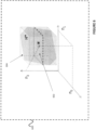
- any achievable solution O shall necessarily be included in the hypercube C* centered on N with its 2*24 faces being respectively at +P D_max and -P C _ max on both sides of the associated component of N as illustrated in 3D in Figure 5 .
- This feature introduces a highly non-linear constraint in the optimization problem to be solved in order to find the best charge-discharge sequence of the battery.
- one embodiment seeks to optimize the charge / discharge sequence of the battery over a calculation period T n with a constant revolving mean-reference SOC over the successive T n , to avoid any mid or long term drift.
- any acceptable net demand curve O shall geometrically comply with : O acceptable ⁇ C inner ⁇ ⁇ H ⁇
- Figure 6 illustrates this condition (hexagonal surface resulting from the intersection of C* and the plan containing N and orthogonal to 1).
- Figure 7 depicts an exemplary computer / computing device 700, hereinafter interchangeably referred to as a computer system 700, where one or more such computing devices 700 may be used to facilitate execution of the above-described method for adaptively maximizing cost savings or profits for utility usage.
- one or more components of the computer system 700 may be used to realize the computer 702.
- the following description of the computing device 700 is provided by way of example only and is not intended to be limiting.
- the example computing device 700 includes a processor 704 for executing software routines. Although a single processor is shown for the sake of clarity, the computing device 700 may also include a multi-processor system.
- the processor 704 is connected to a communication infrastructure 706 for communication with other components of the computing device 700.
- the communication infrastructure 706 may include, for example, a communications bus, cross-bar, or network.
- the computing device 700 further includes a main memory 708, such as a random access memory (RAM), and a secondary memory 710.
- the secondary memory 710 may include, for example, a storage drive 712, which may be a hard disk drive, a solid state drive or a hybrid drive and/or a removable storage drive 714, which may include a magnetic tape drive, an optical disk drive, a solid state storage drive (such as a USB flash drive, a flash memory device, a solid state drive or a memory card), or the like.
- the removable storage drive 714 reads from and/or writes to a removable storage medium 744 in a well-known manner.
- the removable storage medium 744 may include magnetic tape, optical disk, non-volatile memory storage medium, or the like, which is read by and written to by removable storage drive 714.
- the removable storage medium 744 includes a computer readable storage medium having stored therein computer executable program code instructions and/or data.
- the secondary memory 710 may additionally or alternatively include other similar means for allowing computer programs or other instructions to be loaded into the computing device 700.
- Such means can include, for example, a removable storage unit 722 and an interface 740.
- a removable storage unit 722 and interface 740 include a program cartridge and cartridge interface (such as that found in video game console devices), a removable memory chip (such as an EEPROM, EPROM or PROM) and associated socket, a removable solid state storage drive (such as a USB flash drive, a flash memory device, a solid state drive or a memory card), and other removable storage units 722 and interfaces 740 which allow software and data to be transferred from the removable storage unit 722 to the computer system 700.
- the computing device 700 also includes at least one communication interface 724.
- the communication interface 724 allows software and data to be transferred between computing device 700 and external devices via a communication path 726.
- the communication interface 724 permits data to be transferred between the computing device 700 and a data communication network, such as a public data or private data communication network.
- the communication interface 724 may be used to exchange data between different computing devices 700 which such computing devices 700 form part an interconnected computer network. Examples of a communication interface 724 can include a modem, a network interface (such as an Ethernet card), a communication port (such as a serial, parallel, printer, GPIB, IEEE 1394, RJ45, USB), an antenna with associated circuitry and the like.
- the communication interface 724 may be wired or may be wireless.
- Software and data transferred via the communication interface 724 are in the form of signals which can be electronic, electromagnetic, optical or other signals capable of being received by communication interface 724. These signals are provided to the communication interface via the communication path 726.
- the computing device 700 further includes a display interface 702 which performs operations for rendering images to an associated display 730 and an audio interface 732 for performing operations for playing audio content via associated speaker(s) 734.
- Computer program product may refer, in part, to removable storage medium 744, removable storage unit 722, a hard disk installed in storage drive 712, or a carrier wave carrying software over communication path 726 (wireless link or cable) to communication interface 724.
- Computer readable storage media refers to any non-transitory, non-volatile tangible storage medium that provides recorded instructions and/or data to the computing device 700 for execution and/or processing.
- Examples of such storage media include magnetic tape, CD-ROM, DVD, Blu-ray TM Disc, a hard disk drive, a ROM or integrated circuit, a solid state storage drive (such as a USB flash drive, a flash memory device, a solid state drive or a memory card), a hybrid drive, a magneto-optical disk, or a computer readable card such as a SD card and the like, whether or not such devices are internal or external of the computing device 700.
- a solid state storage drive such as a USB flash drive, a flash memory device, a solid state drive or a memory card
- a hybrid drive such as a magneto-optical disk
- a computer readable card such as a SD card and the like
- Examples of transitory or non-tangible computer readable transmission media that may also participate in the provision of software, application programs, instructions and/or data to the computing device 700 include radio or infra-red transmission channels as well as a network connection to another computer or networked device, and the Internet or Intranets including e-mail transmissions and information recorded on Websites and the like.
- the computer programs are stored in main memory 708 and/or secondary memory 710. Computer programs can also be received via the communication interface 724. Such computer programs, when executed, enable the computing device 700 to perform one or more features of embodiments discussed herein. In various embodiments, the computer programs, when executed, enable the processor 704 to perform features of the above-described embodiments. Accordingly, such computer programs represent controllers of the computer system 700.
- Software may be stored in a computer program product and loaded into the computing device 700 using the removable storage drive 714, the storage drive 712, or the interface 740.
- the computer program product may be downloaded to the computer system 700 over the communications path 726.
- the software when executed by the processor 704, causes the computing device 700 to perform functions of embodiments described herein.
- FIG. 7 is presented merely by way of example. Therefore, in some embodiments one or more features of the computing device 700 may be omitted. Also, in some embodiments, one or more features of the computing device 700 may be combined together. Additionally, in some embodiments, one or more features of the computing device 700 may be split into one or more component parts.
- the computing device 700 may be implemented as one or more servers which may be configured to communicate via the Internet, and which may be co-located or geographically distributed, as mentioned above with reference to Figure 2 .
Landscapes
- Business, Economics & Management (AREA)
- Engineering & Computer Science (AREA)
- Economics (AREA)
- Human Resources & Organizations (AREA)
- Strategic Management (AREA)
- General Business, Economics & Management (AREA)
- Physics & Mathematics (AREA)
- Marketing (AREA)
- Theoretical Computer Science (AREA)
- General Physics & Mathematics (AREA)
- Tourism & Hospitality (AREA)
- Health & Medical Sciences (AREA)
- Entrepreneurship & Innovation (AREA)
- Quality & Reliability (AREA)
- Game Theory and Decision Science (AREA)
- Operations Research (AREA)
- Development Economics (AREA)
- Public Health (AREA)
- Water Supply & Treatment (AREA)
- General Health & Medical Sciences (AREA)
- Primary Health Care (AREA)
- Power Engineering (AREA)
- Educational Administration (AREA)
- Supply And Distribution Of Alternating Current (AREA)
- Management, Administration, Business Operations System, And Electronic Commerce (AREA)
- Devices For Checking Fares Or Tickets At Control Points (AREA)
- Meter Arrangements (AREA)
- Control Of Vending Devices And Auxiliary Devices For Vending Devices (AREA)
Description
- The present invention relates broadly, but not exclusively, to a system and method for adaptively maximising cost savings or profits, especially those that are used to maximise cost savings or profits for utility usage.
- Currently, most electricity users have very limited options to reduce their utility bill once they have contracted a given tariff plan. Furthermore, even though the electricity users have some insight into their energy consumption, they do not or cannot act on it to maximise cost savings or profits because it involves processing large volume of data and performing complex prediction in real time.
- Recently, there have been various avenues used to address this problem, in the form of behind-the-meter batteries, usually in combination with solar photo-voltaic generation systems to store any excess energy produced by the solar panels, especially energy that is not consumed right away by the building. This allows consumers to shift, store and trade electricity as they capture the best opportunity to obtain electricity. The problem with this approach is that it is generally based on an "a priori" management of the storage system based on historical building load profiles, with no adjustment based on real-time values.
- A need therefore exists to provide systems and methods for adaptively maximising cost savings or profits that addresses one or more of the above problems.
- Furthermore, other desirable features and characteristics will become apparent from the subsequent detailed description and the appended claims, taken in conjunction with the accompanying drawings and this background of the disclosure.
- Document
US2008/046387 relates to an automated electrical energy control system for residential buildings and has electrical energy generation devices including panels connected to power circuit with switches, where panels convert solar energy into electrical energy. DocumentUS2013/268132 relates to a method for charging and discharging battery storage system and involves generating regulation signal for causing bi-directional charging system to discharge energy storage device, where signal is based on selected charging rate. DocumentUS2014/049109 relates to a system for controlling transfer of energy between electric load location and electric grid and has a system controller to receive created operating parameters and uses parameters to control amount of energy flowing below threshold value. DocumentUS2015/202976 relates to a method for managing power flow at a local site includes site-level charging of electrical devices by a power flow manager. - According to the first aspect of the invention, a system for adaptively maximizing cost savings or profits over a period of time in response to a time-bound variable is provided, comprising: a limited capacity energy storage device configured to provide energy to or receive energy from an electrical consumer, or a producer or an electrical grid; a bilateral flow link operatively coupled to the energy storage device and configured to control the direction and the magnitude of a flow of the energy from or to the energy storage device, the magnitude of the energy being within an operating range comprising a maximum possible flow of energy to the energy storage device (in-flow limit) and a maximum possible flow of energy from the energy storage device (out-flow limit); and a control device operatively coupled to the bilateral flow link; and a bi-directional energy flow measurement device operatively coupled to the control device and the bilateral flow link, wherein the control device controls an energy flow via the bilateral flow link in response to the time-bound variable used to adaptively maximize the cost savings or profits based on an estimated quantity of energy required by or provided by the electrical consumer and/or producer, the fill level of the storage device resulting from a rate of in-flow to the energy storage device or a rate of out-flow from the energy storage device over the period of time and wherein the control device is further configured to calculate an optimal net metered energy (O) to be received from or provided to the electrical grid based on a quantity of energy provided to or received from the energy storage device via the bilateral flow link and the estimated quantity of energy required by or provided by the electrical consumer or the producer, the quantity of energy received from or provided to the electrical grid being measured by the bi-directional energy flow measurement device.
- In an embodiment, the control device is further configured to identify a multi-dimensional search space within which the optimal net metered energy (O) over an identified time period can be found; and reduce the multi-dimensional search space to a first reduced search space (C*) within which the optimal net metered energy (O) can be found based on a maximum rate of in-flow or a maximum rate of out-flow, controllable via the bilateral flow link.
- In an embodiment, the control device is further configured to: identify a sub-space (H*) within which the optimal net metered energy (O) can be found, so that an initial fill level and a targeted final fill level of the energy storage device are met, the sub-space (H*) being within the multi-dimensional search space; and reduce the multi-dimensional search space to a second reduced search space (CH*) within which the optimal net metered energy (O) can be found based on the maximum rate of in-flow or the maximum rate of out-flow controllable via the bilateral flow link and the initial fill level and the targeted final fill level of the energy storage device, the second reduced search space being an intersection between the sub-space (H*) and the first reduced search space (C*) within the multi-dimensional search space.
- In an embodiment, the control device is further configured to reduce the second reduced search space (CH*) to a third reduced search space (CH**) based on a limited capacity of the energy storage device.
- In an embodiment, the control device controls a fill level of the energy storage device via the bilateral flow link based on the difference between the initial fill level and the targeted final fill level of the energy storage device over the period of time, the level difference being used to compensate a drift of an average fill level of the energy storage device over the period of time.
- In an embodiment, the control device determines the level difference based on at least one of (i) a long-term optimization of the average fill level of the energy storage device and (ii) losses to be incurred by system.
- In an embodiment, wherein the energy storage device is a battery.
- In an embodiment, the bilateral flow link comprises a bi-directional converter and a charger, the bi-directional converter and the charger being operatively coupled to the control device.
- In an embodiment, the bi-directional energy flow measurement device is a bi-directional electrical meter.
- According to the second aspect of the invention, a method for adaptively maximizing cost savings or profits in response to a time-bound variable in a system is provided. The system comprises a limited capacity energy storage device configured to provide energy to or receive energy from an electrical consumer, a producer or an electrical grid; a bilateral flow link operatively coupled to the energy storage device and configured to control a direction and a magnitude of a flow of the energy from or to the energy storage device, the magnitude of the energy being within an operating range comprising a maximum possible flow of energy to the energy storage device (in-flow limit) and a maximum possible flow of energy from the energy storage device (out-flow limit); a bi-directional energy flow management device operatively coupled to the control device and the bilateral flow link; and a control device operatively coupled to the bilateral flow link, the method comprising: controlling, by the control device, an energy flow via the bilateral flow link in response to the time-bound variable used to adaptively maximize the cost savings or profits based on an estimated quantity of energy required by or provided by the electrical consumer and/or producer, the fill level of the storage device resulting from a rate of in-flow to the energy storage device or a rate of out-flow from the energy storage device over the period of time; and
calculating, by the control device, an optimal net metered energy (O) to be received from or provided to the electrical grid based on a quantity of energy provided to or received from the energy storage device via the bilateral flow link and the estimated quantity of energy required by or provided by the electrical consumer or the producer. - In an embodiment, the step of adaptively maximizing the cost savings or profits further comprises: identifying, by the control device, a multi-dimensional search space within which the optimal net metered energy (O) over an identified time period can be found; and reducing, by the control device, the multi-dimensional search space to a first reduced search space (C*) within which the optimal net metered energy (O) can be found based on a maximum rate of in-flow or the maximum rate of out-flow controllable via the bilateral flow link.
- In an embodiment, the step of adaptively maximizing the cost savings or profits further comprises: identifying, by the control device, a sub-space (H*) within which the optimal net metered energy (O) can be found, so that an initial fill level and a targeted final fill level of the energy storage device are met, the sub-space (H*) being within the multi-dimensional search space; and reducing, by the control device, the multi-dimensional search space to a second reduced search space (CH*) within which the optimal net metered energy (O) can be found based on the maximum rate of in-flow or the maximum rate of out-flow controllable via the bilateral flow link and the initial fill level and a targeted final fill level of the energy storage device, the second reduced search space being an intersection between the sub-space (H*) and the first reduced search space (C*) within the multi-dimensional search space.
- In an embodiment, the step of adaptively maximizing the cost savings or profits further comprises reducing the second reduced search space (CH*) to a third reduced search space (CH**) based on a limited capacity of the energy storage device.
- In an embodiment, the step of adaptively maximizing the cost savings or profits is further based on the difference between the initial fill level of the energy storage device and the targeted final fill level of the energy storage device over the period of time, the level difference being used to compensate a drift of an average fill level of the energy storage device over the period of time.
- In an embodiment, the method further comprises determining the level difference based on at least one of (i) a long-term optimization of the average fill level of the energy storage device and (ii) losses to be incurred by system.
- According to the third aspect of the invention, a system for adaptively maximizing cost savings or profits over a period of time in response to a time-bound variable is provided, comprising: a limited capacity energy storage device configured to provide energy to or receive energy from an electrical consumer, a producer or an electrical grid; a bilateral flow link coupled to the energy storage device and configured to control a direction and a magnitude of a flow of the energy from or to the energy storage device, the magnitude of the energy being within an operating range comprising a maximum possible flow of energy to the energy storage device (in-flow limit) and a maximum possible flow of energy from the energy storage device (out-flow limit); and a bi-directional energy flow measurement device operatively coupled to the control device and the bilateral flow link, wherein the energy flow via the bilateral flow link is controlled in response to the time-bound variable used to adaptively maximize the cost savings or profits based on an estimated quantity of energy required by or provided by the electrical consumer or the producer, a fill level of the storage device resulting from a rate of in-flow to the energy storage device or a rate of out-flow from the energy storage device over a period of time, and an optimal net metered energy (O), to be received from or provided to the electrical grid, is calculted based on a quantity of energy provided to or received from the energy storage device via the bilateral flow link and the estimated quantity of energy required by or provided by the electrical consumer or producer, the quantity of energy received from or provided to the electrical grid being measured by the bi-directional energy flow measurement device.
- Embodiments of the invention will be better understood and readily apparent to one of ordinary skill in the art from the following written description, by way of example only, and in conjunction with the drawings, in which:
-
Figure 1 shows a block diagram of asystem 100 within which energy can be provided to or received from according to a first embodiment. -
Figure 2 shows a block diagram of asystem 200 within which energy can be provided to or received from according to a second embodiment. -
Figure 3 shows a block diagram of asystem 300 within which energy can be provided to or received from according to a third embodiment. -
Figure 4 illustrates how demand curves change in response to a charge / discharge sequence of a battery. -
Figure 5 illustrates a first reduced search space (C*) within which an optimal net metered energy (O) can be found. -
Figure 6 illustrates a second reduced search space (CH*) that is derived from the first reduced search space (C*) within which an optimal net metered energy (O) can be found. -
Figure 7 shows a schematic diagram of a computer system suitable for use in executing a method. - Embodiments of the present invention will be described, by way of example only, with reference to the drawings. Like reference numerals and characters in the drawings refer to like elements or equivalents.
- Some portions of the description which follows are explicitly or implicitly presented in terms of algorithms and functional or symbolic representations of operations on data within a computer memory. These algorithmic descriptions and functional or symbolic representations are the means used by those skilled in the data processing arts to convey most effectively the substance of their work to others skilled in the art. An algorithm is here, and generally, conceived to be a self-consistent sequence of steps leading to a desired result. The steps are those requiring physical manipulations of physical quantities, such as electrical, magnetic or optical signals capable of being stored, transferred, combined, compared, and otherwise manipulated.
- Unless specifically stated otherwise, and as apparent from the following, it will be appreciated that throughout the present specification, discussions utilizing terms such as "scanning", "calculating", "determining", "replacing", "generating", "initializing", "outputting", "receiving", "retrieving", "identifying", "predicting", "processing", or the like, refer to the action and processes of a computer system, or similar electronic device, that manipulates and transforms data represented as physical quantities within the computer system into other data similarly represented as physical quantities within the computer system or other information storage, transmission or display devices.
- The present specification also discloses apparatus for performing the operations of the methods. Such apparatus may be specially constructed for the required purposes, or may comprise a computer or other device selectively activated or reconfigured by a computer program stored in the computer. The algorithms and displays presented herein are not inherently related to any particular computer or other apparatus. Various machines may be used with programs in accordance with the teachings herein. Alternatively, the construction of more specialized apparatus to perform the required method steps may be appropriate. The structure of a computer will appear from the description below.
- In addition, the present specification also implicitly discloses a computer program, in that it would be apparent to the person skilled in the art that the individual steps of the method described herein may be put into effect by computer code. The computer program is not intended to be limited to any particular programming language and implementation thereof. It will be appreciated that a variety of programming languages and coding thereof may be used to implement the teachings of the disclosure contained herein. Moreover, the computer program is not intended to be limited to any particular control flow. There are many other variants of the computer program, which can use different control.
- Furthermore, one or more of the steps of the computer program may be performed in parallel rather than sequentially. Such a computer program may be stored on any computer readable medium. The computer readable medium may include storage devices such as magnetic or optical disks, memory chips, or other storage devices suitable for interfacing with a computer. The computer readable medium may also include a hard-wired medium such as exemplified in the Internet system, or wireless medium such as exemplified in the GSM mobile telephone system. The computer program when loaded and executed on such a computer effectively results in an apparatus that implements the steps of the preferred method.
- Various embodiments of the present invention relate to systems and methods for adaptively maximizing cost savings or profits for utility usage. In an embodiment, the method is a computer-implemented method which adaptively maximizes cost savings or profits for utility usage in response to a time-bound variable.
-
FIG 1 illustrates a block diagram of asystem 100 within which energy (for example, electrical energy) can be provided to or received from according to a first embodiment. Thesystem 100 may be a Stationary Energy Storage System (SESS) which operates on operating principles of distributed behind-the-meter electrical system. Thesystem 100 may include anenergy storage device 102 operatively coupled to a bilateraladjustable flow link 104 and acontrol device 106. The bilateraladjustable flow link 104 is also operatively coupled to thecontrol device 106 and anelectrical junction 110 which is further coupled to an electrical consumer and/orproducer 108. Thesystem 100 further comprises a bi-directional energy flow measurement device (or meter) 112 that is operatively coupled to thecontrol device 106, theelectrical junction 110 and anelectrical grid 114. Theelectrical junction 110 is a connecting point of the system (or SESS) 100. The transactional energy flow resulting from the operation of the SESS is diverted from or injected to the nominal flow between theelectrical grid 114 and the electrical consumer and/orproducer 108. - To illustrate clearly this interchangeability and compatibility of hardware, firmware, and software, various illustrative components, blocks, modules, circuits, and steps are described generally in terms of their functionality. Whether such functionality is implemented as hardware, firmware, or software depends upon the particular application and design constraints imposed on the overall system. Those familiar with the concepts described herein may implement such functionality in a suitable manner for each particular application.
- The
energy storage device 102 may be any energy type known in the art, such as but without limitation, lithium-ion battery, sodium-ion battery, redox flow battery, lead-acid battery, nickel-metal-hydride battery, nickel-cadmium battery, or other fluid-energy sources, and may have a limited capacity. The limited capacity of theenergy storage device 102 determines a fill level of theenergy storage device 102. In an embodiment, theenergy storage device 102 is a battery and the limited capacity refers to battery capacity. It is to be understood that the battery capacity for a given size battery depends on temperature, cut off voltages, charge/discharge rates or other battery parameters, and health of the battery depends on current battery parameters relative to an initial specification of the battery, e.g., from an original equipment manufacturer (OEM), and the past usage of the battery. In this regard, operating status parameters may indicate, for example, a current percentage of assumed (e.g., specified) capacity for the battery or battery network. A maximum actual capacity or intern resistivity (e.g., health) of a battery may be determined by measuring voltage, current, and temperature during charge and discharge cycles, and comparing those measurements to data sets known to represent various levels of health. - The
energy storage device 102 is configured to (i), receive energy from theelectrical grid 114 or (ii) receive energy from theelectrical producer 108 or (iii) receive energy from theelectrical grid 114 and theelectrical producer 108, or alternatively (iv) provide energy to theelectrical consumer 108 or (v) supply energy to theelectrical grid 114 or (vi) provide energy to theelectrical consumer 108 and supply energy to theelectrical grid 114. In an embodiment, the bi-directional energyflow measurement device 112 is a bi-directional electrical meter that may be configured to measure a quantity of energy received from or provided to theelectrical grid 114. - The bilateral adjustable flow link 104 (or bilateral flow link) is configured to control a direction and a magnitude of a flow of energy from or to the
energy storage device 102. The magnitude of the energy is within an operating range comprising a maximum possible flow of energy to the energy storage device 102 (or in-flow limit) and a maximum possible flow of energy from the energy storage device 102 (or out-flow limit). In other words, the bilateraladjustable flow link 104 functionally accounts for the energy flow flowing between theenergy storage device 102 and theelectrical grid 114 and/or the electrical consumer and/orproducer 108. That is, the bilateraladjustable flow link 104 allows for the flow of energy to and from theenergy storage device 102 at an adjustable and controllable rate and also handles necessary conversions, if necessary. - The
control device 106 is configured to control the energy flow via the bilateral flow link 104 in response to the time-bound variable used to adaptively maximise the cost savings or profits based on an estimated quantity of energy required by or provided by the electrical consumer and/or producer. The time-bound variable may be based on the fill level of theenergy storage device 102. The fill level of theenergy storage device 102 results from a rate of in-flow to theenergy storage device 102 or a rate of out-flow from theenergy storage device 102. Thecontrol device 106 may be further configured to calculate an optimal net metered energy (O) to be received from or provided to theelectrical grid 114 based on a quantity of energy provided to or received from theenergy storage device 102 via thebilateral flow link 104 and the estimated quantity of energy required by or provided by the electrical consumer and/orproducer 108. The quantity of energy received from or provided to theelectrical grid 114 may be measured by the bi-directional energyflow measurement device 112. - In the embodiment, the
control device 106 may be further configured to identify a multi-dimensional search space within which the optimal net metered energy (O) over an identified time period can be found; and reduce the multi-dimensional search space to a first reduced search space (C*) within which the optimal net metered energy (O) can be found based on a maximum rate of in-flow or a maximum rate of out-flow, controllable via thebilateral flow link 104. In another embodiment, thecontrol device 106 may be further configured to identify a sub-space (H*) within which the optimal net metered energy (O) can be found, so that an initial fill level and a targeted final fill level of theenergy storage device 102 are met. The sub-space (H*) is one that is within the multi-dimensional search space. Thecontrol device 106 may also be configured to reduce the multi-dimensional search space to a second reduced search space (CH*) within which the optimal net metered energy (O) can be found based on the maximum rate of in-flow or the maximum rate of out-flow controllable via thebilateral flow link 104 and an initial fill level and a targeted final fill level of theenergy storage device 102, the second reduced search space being an intersection between the sub-space (H*) and the first reduced search space (C*) within the multi-dimensional search space. The initial fill level refers to the fill level of theenergy storage device 102 at the beginning of a period of time and the targeting final fill level refers to the projected fill level of theenergy storage device 102 at the end of the same period of time. - In an embodiment, the
control device 106 is further configured to reduce the second reduced search space (CH*) to a third reduced search space (CH**) based on a limited capacity of theenergy storage device 102. It is to be understood that various numerical computations may be used to reduce the second reduced search space (CH*) to the third reduced search space (CH**). For example, it is possible to withdraw all points from the second reduced search space (CH*) so that the evolution of the corresponding fill level over the period of time is never negative or greater than the limited capacity of the energy storage device. The reduced result is the third reduced search space (CH**). - Further, the
control device 106 controls the fill level of theenergy storage device 102 via the bilateral flow link 104 based on a difference between the initial fill level and the targeted final fill level of the energy storage device over the period of time, the level difference being for instance used to compensate a drift of an average fill level of theenergy storage device 102 over the period of time. In another embodiment, thecontrol device 106 determines the level difference based on at least one of (i) the long-term optimization of the average fill level of theenergy storage device 102 and (ii) losses to be incurred by thesystem 100. - The
electrical grid 114 may stand for a quasi-infinite source or a well of energy which runs the SESS. The "quasi-infinite" nature of the grid refers to the fact that due to its dimension relatively to the SESS, its state an features are marginally affected by the operation of the SESS, and can be considered as independent from the SESS individually. - The bi-directional energy
flow measurement device 112 is configured to measure energy flow that is exchanged between (i) the electrical consumer and/orproducer 108 and theelectrical grid 114 and/or (ii) theenergy storage device 102 and theelectrical grid 114. For example, if theenergy storage device 102 is a battery and the electrical consumer and/orproducer 108 is a consumer only, the bi-directional energyflow measurement device 112 may be a meter that is configured to measure electrical energy flow flowing from theelectrical grid 114 to theenergy storage 102 and theelectrical consumer 108. A person skilled in the art will understand that the meter may be used by the utility as a reference for billing purpose. -
FIG 2 illustrates a block diagram of asystem 200 within which energy can be provided to or received from according to a second embodiment. In the second embodiment, theenergy storage device 202 may be a battery which is operatively coupled to the bilateral and adjustable flow link (or bilateral flow link) 204. For example, theenergy storage device 202 may be a battery, a combination or collection of batteries (including redox-flow devices), any alternate energy storage device (for example, flywheel, super-capacitors or hydrogen cycle). In this embodiment, thebilateral flow link 204 includes a battery management system 204(a) and a bi-directional converter and charger 204(b). - The battery management system 204(a) may be configured to perform low-level management of the
battery 202, such as by protecting thebattery 202 from operating outside predetermined operating limits, monitoring the operating state of thebattery 202, processing the measurements of operating parameter of thebattery 202, reporting the operating data of thebattery 202 and controlling the operating environment of thebattery 202. - The bi-directional converter and charger 204(b) may be operatively coupled to a
control device 206. Thecontrol device 206 may include a controller 206(a) and a computer 206(b). The bi-directional converter and charger 204(b) is configured to handle various conversions between the electrical network and thebattery 202. Further, the bi-directional converter and charger 204(b) is preferably configured to directly/ indirectly charge or discharge thebattery 202. - In this embodiment, the
control device 206 comprises a controller 206(a) and a remote computer 206(b) which may function together to perform various operations. Thecontrol device 206 is operatively coupled to a bi-directional energyflow measurement device 212. In this embodiment, the bi-directional energy flow measurement device 204(b) is coupled to an electrical consumer and/orproducer 208 via anelectrical junction 210. Theelectrical junction 210 is a connecting point of the system (or SESS) 200. The transactional energy flow resulting from the operation of the SESS is diverted from or injected to the nominal flow between theelectrical grid 214 and the electrical consumer and/orproducer 208. - The remote computer 206(b) may be implemented as one or more servers which may be configured to communicate via the Internet, and which may be co-located or geographically distributed, for example, as will be appreciated by those skilled in the art. That is, in one example embodiment, the remote computer 206(b) may be part of a cloud computing system. The electrical consumer and/or
producer 208 accounts for an electrical load (for example: all the electrical devices of a building where the SESS is installed). From a functional perspective, the electrical consumer and/orproducer 208 may be considered as an electrical energy consumer and / or an electrical energy producer. - Most electrical networks installed in buildings are generally in alternate current (AC) and an
energy storage device 202 is generally a direct current (DC) device. For example, in this embodiment, the electrical consumer and/orproducer 208 may include a DC electrical source 208(a), an AC electrical consumer 208(b) and an AC electrical source 208(c). The DC electrical source 208(a) may be directly coupled to the battery management system 204(a) and may be configured to charge/discharge theenergy storage device 202. The AC electrical source 208(c) is directly coupled to theelectrical junction 210 and may be configured to provide energy via theelectrical junction 210. The AC electrical consumer 208(b) is directly coupled to theelectrical junction 210 and may be configured to consume energy from theelectrical grid 214 and/or from theenergy storage device 202 via theelectrical junction 210. - Additionally, an energy management system (EMS) may be operatively coupled to the SESS and is configured to supervise operations of the SESS by collecting various internal data (status, measurements, etc.) of the system. Further, the EMS is configured to process the internal data (for example, data concerning the energy storage device 202) with other external data according to one of various management strategies and pilot the SESS accordingly. For example, in various embodiments, the EMS may be the
control device 206 and may be configured to control the bi-directional inverter and charger 204(b). - Management of the SESS may be broken into the following operating steps which may be looped over time. The EMS may be configured to collect the latest internal operating data of the system (e.g., parameters, status) and external contextual data required by further computational steps. The EMS may also be configured to process and analyse the available data. In an implementation, the EMS may be configured to forecast potential environment values. Based on the potential prediction, the EMS may be configured to run some optimization routine aiming at optimizing the operations of the SESS according to at least one performance criteria. Eventually, the EMS may be configured to operate the SESS in accordance with the results of the optimization routine. The performance criteria may be technical, economical and / or environmental.
-
Figure 3 shows a block diagram of asystem 300 within which energy can be provided to or received from according to a third embodiment. In this embodiment, it can be seen that the energy storage device may be afluid storage device 302 which is directly coupled to acontrol device 306 and a bilateraladjustable flow link 304. The bilateraladjustable flow link 304 is also coupled to thecontrol device 306 and aflow junction 310 which is further coupled to a fluid consumer and/orproducer 308. Thesystem 300 further comprises a bi-directional energy flow measurement device (or meter) 312 that is operatively coupled to thecontrol device 306, theflow junction 310 and a fluidexternal grid 314. - The battery described in
Figure 1 andFigure 2 can be assimilated as a first approximation to an energy tank (or an energy storage capacity device) with: - Limited Capacity: its Nominal energy Storage Capacity (NSC)
- Limited possible filing / pouring flow: its maximum charge and discharge powers
- In the embodiments that follow, a state of charge (SOC) of a battery may also be known as a fill level of the energy storage capacity device e.g. the ratio of stored energy relatively to the NSC. Hence, it comes


- Round-trip Efficiency For the sake of simplicity and clarity, the round-trip efficiency of the SESS is set to 1. That is, it is assumed that there is no loss of energy in a charge / discharge cycle. This approximation is coarse as the actual round-trip efficiency may significantly differ from 1 in real batteries, but it does not affect the methodology since a round-trip efficiency different from 1 can be handled by means of corrective coefficients applied to respectively the in-flow and out-flow of energy transiting through the bilateral
adjustable flow link 304. - Ageing: A typical electrochemical battery has a limited lifecycle, since each and every charge / discharge cycle is slightly modifying the composition of the battery, affecting its performances. From an economic perspective, a battery may be considered as a consumable item with a certain "cycling potential". Each and every cycle is consuming this potential, and then has an intrinsic related cost. When used for energy trading, this "ageing cost" shall be lower than the trading profit resulting from arbitrage in energy price.
- In the following calculations, an optimization period of 24 hours is considered, in accordance with a natural underlying daily cycle observed in most electrical load curves. It is to be understood that the optimization period of 24 hours is only an example and other optimization periods are also possible (e.g., 12 hours, 48 hours, etc.) in the following calculations. For the sake of simplicity, this optimization period is divided into 24 regular 1h time-steps (Δt). Other regular time-steps may be used without prejudice to the generality of the exposed method. An identification and use of the Greater Common Divisor of the time-steps allows for the return to the method with regular time-steps. In the following calculations, the following will apply for sign conventions:
- at the meter: the energy flow is considered from the grid perspective. Thus it is counted:
- positively when energy is injected into the grid
- negatively when energy is drawn from the grid
- at battery level: the energy flow in the battery is counted:
- positively when the battery is discharging
- negatively when the battery is charging
- at consumer / producer level: the energy flow is counted:
- positively when acting as a consumer
- negatively when acting as a producer
- For the sake of simplicity, it is considered that bid and offer (or buy and sell) energy prices from or to the grid are equal. The method can be generalized to situations where bid and offer prices differ, at the cost of increased complexity of its implementation, but without fundamental differences in the operating principle.
- In the calculations below, the following definitions apply;
- Tn : the umpteenth (n) calculation period (duration = T = 24h here)
- SOC 0(Tn ) : the State Of Charge of the battery at the beginning of period Tn
- SOCi (Tn ) : the State Of Charge of the battery at time-step i of period Tn
- SOC 24(Tn ): the State Of Charge of the battery at the end of period Tn
- PC_max : the maximum Charging Power
- PD_max : the maximum Discharging Power
- Over a 24h calculation period that is divided into 1 h time-steps, the time-profile of any parameter x(Tn) (for example, electric load price, etc.) may be a 24 time-series {x0(Tn),x1(Tn)..., ,x23(Tn)}, which can be represented by a 24 - dimensional vector X

- L(Tn): the vector accounting for the 24h raw load profile forecasted over Tn. According to the sign convention exposed above, all its coordinates are positive.
- S(Tn): the vector accounting for the 24h self-generation (e. g. Solar PV) profile forecasted over Tn. According to the sign convention exposed above, all its coordinates are negative.
- N(Tn): the vector accounting for the 24h power flow profile forecasted over Tn at the meter, without battery in the system. Hence it also stands for a metering reference.
- K(Tn): the vector accounting for the 24h price profile of energy to/from the grid, forecasted over Tn (with the assumption that bid and offer prices are equal).
- B(Tn): the vector accounting for the 24h charge /discharge power-order profile to be followed by the controller managing the battery.
- O(Tn): the vector accounting for the 24h power flow profile forecasted over Tn at the meter, with the battery in the system.
- Taking out the power losses in the system, and taking into account the aforementioned sign conventions, the following will be obtained:


-
Figure 4 illustrates how demand curves change in response to a charge / discharge sequence of a battery.Line 402 represents the power flow profile forecasted over Tn at the meter, without the battery, O(Tn).Line 404 represents the power flow profile forecasted over Tn at the meter, with the battery, N(Tn). 406 represents the 24h charge / discharge power profile of the battery. In other words, it can be seen thatline 402 is a summation ofline - Further, the forecasted reference-cost of energy Cref over Tn can be calculated as follows:

- In the followings, most calculations are considered over a given similar Tn period, and the "(Tn )" notation may be omitted for the sake of readability. When omitted, all vectors and components refer to this same generic implicit Tn.
- The charging / discharging power constraints of the battery, can be written as follows


- Based on the above equations, it means that any achievable solution O shall necessarily be included in the hypercube C* centered on N with its 2*24 faces being respectively at +PD_max and -P C_max on both sides of the associated component of N as illustrated in 3D in
Figure 5 . - The storage capacity constraint of the battery can be mathematically translated as follows:

- This feature introduces a highly non-linear constraint in the optimization problem to be solved in order to find the best charge-discharge sequence of the battery.
- Managing the charge / discharge sequence of a battery and optimizing it over successive time periods Tn implies a control of the evolution of the mean-reference SOC of the battery Indeed, by definition, we have:

- To avoid a mid/long-term drift of the mean reference SOC, and to be able to perform long-term cycle (duration greater than Tn ) of the battery, an additional constraint over any period Tn in the form of a bias δn is introduced between the initial and the final SOC of the battery.

- Basically, if no long-term optimization is performed, one embodiment seeks to optimize the charge / discharge sequence of the battery over a calculation period Tn with a constant revolving mean-reference SOC over the successive Tn, to avoid any mid or long term drift. Thus, the following SOC condition from (12) can be considered:

- Given the forecasted load curve L and solar PV output S, the raw demand curve N is calculated from (4), and ∑ni over Tn is considered as a reference that can be known as Nn in the following. Thus, using (5) constraint (13) eventually becomes:

- Using vectors, the equation above becomes:

- The above equation actually is the definition of the hyper-plan H* containing points N and orthogonal to
vector 1. - Combining this constraint with the charge / discharge limitation, any acceptable net demand curve O shall geometrically comply with :

-
Figure 6 illustrates this condition (hexagonal surface resulting from the intersection of C* and the plan containing N and orthogonal to 1). -
Figure 7 depicts an exemplary computer /computing device 700, hereinafter interchangeably referred to as acomputer system 700, where one or moresuch computing devices 700 may be used to facilitate execution of the above-described method for adaptively maximizing cost savings or profits for utility usage. In addition, one or more components of thecomputer system 700 may be used to realize thecomputer 702. The following description of thecomputing device 700 is provided by way of example only and is not intended to be limiting. - As shown in
Figure 7 , theexample computing device 700 includes a processor 704 for executing software routines. Although a single processor is shown for the sake of clarity, thecomputing device 700 may also include a multi-processor system. The processor 704 is connected to acommunication infrastructure 706 for communication with other components of thecomputing device 700. Thecommunication infrastructure 706 may include, for example, a communications bus, cross-bar, or network. - The
computing device 700 further includes a main memory 708, such as a random access memory (RAM), and asecondary memory 710. Thesecondary memory 710 may include, for example, astorage drive 712, which may be a hard disk drive, a solid state drive or a hybrid drive and/or aremovable storage drive 714, which may include a magnetic tape drive, an optical disk drive, a solid state storage drive (such as a USB flash drive, a flash memory device, a solid state drive or a memory card), or the like. Theremovable storage drive 714 reads from and/or writes to a removable storage medium 744 in a well-known manner. The removable storage medium 744 may include magnetic tape, optical disk, non-volatile memory storage medium, or the like, which is read by and written to byremovable storage drive 714. As will be appreciated by persons skilled in the relevant art(s), the removable storage medium 744 includes a computer readable storage medium having stored therein computer executable program code instructions and/or data. - In an alternative implementation, the
secondary memory 710 may additionally or alternatively include other similar means for allowing computer programs or other instructions to be loaded into thecomputing device 700. Such means can include, for example, a removable storage unit 722 and an interface 740. Examples of a removable storage unit 722 and interface 740 include a program cartridge and cartridge interface (such as that found in video game console devices), a removable memory chip (such as an EEPROM, EPROM or PROM) and associated socket, a removable solid state storage drive (such as a USB flash drive, a flash memory device, a solid state drive or a memory card), and other removable storage units 722 and interfaces 740 which allow software and data to be transferred from the removable storage unit 722 to thecomputer system 700. - The
computing device 700 also includes at least onecommunication interface 724. Thecommunication interface 724 allows software and data to be transferred betweencomputing device 700 and external devices via acommunication path 726. In various embodiments of the inventions, thecommunication interface 724 permits data to be transferred between thecomputing device 700 and a data communication network, such as a public data or private data communication network. Thecommunication interface 724 may be used to exchange data betweendifferent computing devices 700 whichsuch computing devices 700 form part an interconnected computer network. Examples of acommunication interface 724 can include a modem, a network interface (such as an Ethernet card), a communication port (such as a serial, parallel, printer, GPIB, IEEE 1394, RJ45, USB), an antenna with associated circuitry and the like. Thecommunication interface 724 may be wired or may be wireless. Software and data transferred via thecommunication interface 724 are in the form of signals which can be electronic, electromagnetic, optical or other signals capable of being received bycommunication interface 724. These signals are provided to the communication interface via thecommunication path 726. - As shown in
Figure 7 , thecomputing device 700 further includes adisplay interface 702 which performs operations for rendering images to an associated display 730 and anaudio interface 732 for performing operations for playing audio content via associated speaker(s) 734. - As used herein, the term "computer program product" may refer, in part, to removable storage medium 744, removable storage unit 722, a hard disk installed in
storage drive 712, or a carrier wave carrying software over communication path 726 (wireless link or cable) tocommunication interface 724. Computer readable storage media refers to any non-transitory, non-volatile tangible storage medium that provides recorded instructions and/or data to thecomputing device 700 for execution and/or processing. Examples of such storage media include magnetic tape, CD-ROM, DVD, Blu-ray™ Disc, a hard disk drive, a ROM or integrated circuit, a solid state storage drive (such as a USB flash drive, a flash memory device, a solid state drive or a memory card), a hybrid drive, a magneto-optical disk, or a computer readable card such as a SD card and the like, whether or not such devices are internal or external of thecomputing device 700. Examples of transitory or non-tangible computer readable transmission media that may also participate in the provision of software, application programs, instructions and/or data to thecomputing device 700 include radio or infra-red transmission channels as well as a network connection to another computer or networked device, and the Internet or Intranets including e-mail transmissions and information recorded on Websites and the like. - The computer programs (also called computer program code) are stored in main memory 708 and/or
secondary memory 710. Computer programs can also be received via thecommunication interface 724. Such computer programs, when executed, enable thecomputing device 700 to perform one or more features of embodiments discussed herein. In various embodiments, the computer programs, when executed, enable the processor 704 to perform features of the above-described embodiments. Accordingly, such computer programs represent controllers of thecomputer system 700. - Software may be stored in a computer program product and loaded into the
computing device 700 using theremovable storage drive 714, thestorage drive 712, or the interface 740. Alternatively, the computer program product may be downloaded to thecomputer system 700 over thecommunications path 726. The software, when executed by the processor 704, causes thecomputing device 700 to perform functions of embodiments described herein. - It is to be understood that the embodiment of
Figure 7 is presented merely by way of example. Therefore, in some embodiments one or more features of thecomputing device 700 may be omitted. Also, in some embodiments, one or more features of thecomputing device 700 may be combined together. Additionally, in some embodiments, one or more features of thecomputing device 700 may be split into one or more component parts. - For example, in some embodiments, the
computing device 700 may be implemented as one or more servers which may be configured to communicate via the Internet, and which may be co-located or geographically distributed, as mentioned above with reference toFigure 2 . - It is to be understood that a cloud computing system can be composed of any number of
computing devices 700 having at least one of the above mentioned functions. The cloud computing system may be a private or public system. Thecomputing devices 700 can be in communication with one another across any communication system or network. That is, the cloud computing system can support a single cloud or service or any number of discrete clouds or services.
Claims (14)
- A system (100) for adaptively maximizing cost savings or profits over a period of time in response to a time-bound variable, comprising:a limited capacity energy storage device (102) configured to provide energy to or receive energy from an electrical consumer (108), a producer (108) and/or an electrical grid (114);a bilateral flow link (104) operatively coupled to the limited capacity energy storage device (102) and configured to control a direction and an adjustable magnitude of a flow of the energy from or to the limited capacity energy storage device (102), the magnitude of the energy being adjustable within an operating range comprising a maximum possible flow of energy to the limited capacity energy storage device (102) (an in-flow limit) and a maximum possible flow of energy from the limited capacity energy storage device (102) (an out-flow limit);a control device (106) operatively coupled to the bilateral flow link (104) and configured to calculate an optimal net metered energy (O) to be received from or provided to the electrical grid (114) based on a quantity of energy provided to or received from the limited capacity energy storage device (102) via the bilateral flow link (104) and the estimated quantity of energy required by or provided by the electrical consumer and/or the producer (108), and is further configured to calculate the optimal net metered energy (O) based on a level difference between an initial fill level of the limited capacity energy storage device (102) and a targeted final fill level of the limited capacity energy storage device (102) over the period of time, the level difference being determined based on a long-term optimization of the average fill level of the limited capacity energy storage device (102) and being used to compensate a drift of an average fill level of the limited capacity energy storage device (102) over the period of time; anda bi-directional energy flow measurement device (112) operatively coupled to the control device (106) and the bilateral flow link (104),wherein the control device (106) is configured to control the direction and to adjust the magnitude of the flow of the energy from or to the limited capacity energy storage device (102) via the bilateral flow link (104) in response to the optimal net metered energy (O) and the time-bound variable, the time- bound variable being based on(a) a fill level of the limited capacity energy storage device (102) resulting from a rate of in-flow to the limited capacity energy storage device (102) over the period of time or a rate of out-flow from the limited capacity energy storage device (102) over the period of time and(b) an estimated quantity of energy required by or provided by the electrical consumer and/or the producer (108), andwherein the quantity of energy received from or provided to the electrical grid (114) is measured by the bi-directional energy flow measurement device (112).
- The system according to claim 1, wherein the control device is further configured to:identify a multi-dimensional search space within which the optimal net metered energy (O) over an identified time period can be found; andreduce the multi-dimensional search space to a first reduced search space (C*) within which the optimal net metered energy (O) can be found based on a maximum rate of in-flow or a maximum rate of out-flow controllable via the bilateral flow link.
- The system according to claim 2, wherein the control device is further configured to:identify a sub-space (H*) within which the optimal net metered energy (O) can be found, so that the initial fill level and the targeted final fill level of the limited capacity energy storage device are met, the sub-space (H*) being within the multi-dimensional search space; andreduce the multi-dimensional search space to a second reduced search space (CH*) within which the optimal net metered energy (O) can be found based on the maximum rate of in-flow or the maximum rate of out-flow controllable via the bilateral flow link and the initial fill level and the targeted final fill level of the limited capacity energy storage device, the second reduced search space being an intersection between the sub-space (H*) and the first reduced search space (C*) within the multi-dimensional search space.
- The system according to claim 3, wherein the control device is further configured to reduce the second reduced search space (CH*) to a third reduced search space (CH**) based on a limited capacity of the limited capacity energy storage device.
- The system according to any one of the preceding claims, wherein the control device further determines the level difference based on losses to be incurred by system.
- The system according to any one of the preceding claims, wherein the limited capacity energy storage device is a battery.
- The system according to claim 6, wherein the bilateral flow link comprises a bi-directional converter and a charger, the bi-directional converter and the charger being operatively coupled to the control device.
- The system according to any one of the preceding claims, wherein the bi-directional energy flow measurement device is a bi-directional electrical meter.
- A method for adaptively maximizing cost savings or profits in response to a time-bound variable in a system, the system comprising:a limited capacity energy storage device configured to provide energy to or receive energy from an electrical consumer, a producer and/or an electrical grid;a bilateral flow link operatively coupled to the limited capacity energy storage device and configured to control a direction and an adjustable magnitude of a flow of the energy from or to the limited capacity energy storage device, the magnitude of the energy being adjustable within an operating range comprising a maximum possible flow of energy to the limited capacity energy storage device (an in-flow limit) and a maximum possible flow of energy from the limited capacity energy storage device (an out-flow limit);a bi-directional energy flow measurement device operatively coupled to the bilateral flow link; anda control device operatively coupled to the bilateral flow link and the bi-directional energy flow measurement device, the method comprising:calculating, by the control device, an optimal net metered energy (O) to be received from or provided to the electrical grid based on a quantity of energy provided to or received from the limited capacity energy storage device via the bilateral flow link and the estimated quantity of energy required by or provided by the electrical consumer and/or the producer, and further calculating the optimal net metered energy (O) based on a level difference between an initial fill level of the limited capacity energy storage device and a targeted final fill level of the limited capacity energy storage device over the period of time, the level difference being determined based on a long-term optimization of the average fill level of the limited capacity energy storage device and being used to compensate a drift of an average fill level of the limited capacity energy storage device over the period of time; andcontrolling, by the control device, the direction and the adjustable magnitude of the flow of the energy from or to the limited capacity energy storage device via the bilateral flow link in response to the optimal net metered energy (O) and the time-bound variable, the time-bound variable being based on (a) the fill level of the limited capacity energy storage device resulting from a rate of in-flow to the limited capacity energy storage device over the period of time or a rate of out-flow from the limited capacity energy storage device over the period of time and (b) an estimated quantity of energy required by or provided by the electrical consumer and/or the producer.
- The method according to claim 9, wherein the step of calculating the optimal net metered energy (O) to be received from or provided to the electrical grid comprises:identifying, by the control device, a multi-dimensional search space within which the optimal net metered energy (O) over an identified time period can be found; andreducing, by the control device, the multi-dimensional search space to a first reduced search space (C*) within which the optimal net metered energy (O) can be found based on a maximum rate of in-flow or a maximum rate of out-flow controllable via the bilateral flow link.
- The method according to claim 10, wherein the step of calculating the optimal net metered energy (O) to be received from or provided to the electrical grid further comprises:identifying, by the control device, a sub-space (H*) within which the optimal net metered energy (O) can be found, so that the initial fill level and the targeted final fill level of the limited capacity energy storage device are met, the sub-space (H*) being within the multi-dimensional search space; andreducing, by the control device, the multi-dimensional search space to a second reduced search space (CH*) within which the optimal net metered energy (O) can be found based on the maximum rate of in-flow or the maximum rate of out-flow controllable via the bilateral flow link and the initial fill level and the targeted final fill level of the limited capacity energy storage device, the second reduced search space being an intersection between the sub-space (H*) and the first reduced search space (C*) within the multi-dimensional search space.
- The method according to claim 11, wherein the step of calculating the optimal net metered energy (O) to be received from or provided to the electrical grid further comprises reducing the second reduced search space (CH*) to a third reduced search space (CH**) based on a limited capacity of the limited capacity energy storage device.
- The method according to any one of claims 9-12, further comprising determining the level difference based on losses to be incurred by system.
- A system for adaptively maximizing cost savings or profits over a period of time in response to a time-bound variable, comprising:a limited capacity energy storage device configured to provide energy to or receive energy from an electrical consumer, a producer and/or an electrical grid;a bilateral flow link coupled to the limited capacity energy storage device and configured to control a direction and an adjustable magnitude of a flow of the energy from or to the limited capacity energy storage device, the adjustable magnitude of the energy being within an operating range comprising a maximum possible flow of energy to the limited capacity energy storage device (an in-flow limit) and a maximum possible flow of energy from the limited capacity energy storage device (an out-flow limit); anda bi-directional energy flow measurement device operatively coupled to the bilateral flow link,wherein the direction and the adjustable magnitude of the flow of the energy from or to the limited capacity energy storage device via the bilateral flow link is controlled in response to the time-bound variable used to adaptively maximize the cost savings or profits and an optimal net metered energy (O) to be received from or provided to the electrical grid, andwherein the direction and the adjustable magnitude of the flow of the energy from or to the limited capacity energy storage device via the bilateral flow link is controlled over a period of time in response to a fill level of the limited capacity energy storage device via the bilateral flow link based on a level difference between an initial fill level and a targeted final fill level of the limited capacity energy storage device over the period of time, the level difference being determined based on a long-term optimization of the average fill level of the limited capacity energy storage device and being used to compensate a drift of an average fill level of the energy storage device over the period of time, andwherein the time-bound variable is based on (a) the fill level of the limited capacity energy storage device resulting from a rate of in-flow to the limited capacity energy storage device or a rate of out-flow from the limited capacity energy storage device over the period of time and (b) an estimated quantity of energy required by or provided by the electrical consumer and/or the producer, andwherein the optimal net metered energy (O) is calculated based on a quantity of energy provided to or received from the limited capacity energy storage device via the bilateral flow link and the estimated quantity of energy required by or provided by the electrical consumer and/or producer, the quantity of energy received from or provided to the electrical grid being measured by the bi-directional energy flow measurement device.
Applications Claiming Priority (2)
| Application Number | Priority Date | Filing Date | Title |
|---|---|---|---|
| SG10201602403RA SG10201602403RA (en) | 2016-03-28 | 2016-03-28 | A System And Method For Adaptively Maximizing Cost Savings Or Profits For Utility Usage |
| PCT/SG2017/050136 WO2017171636A1 (en) | 2016-03-28 | 2017-03-17 | A system and method for adaptively maximizing cost savings or profits for utility usage |
Publications (4)
| Publication Number | Publication Date |
|---|---|
| EP3437032A1 EP3437032A1 (en) | 2019-02-06 |
| EP3437032A4 EP3437032A4 (en) | 2019-10-09 |
| EP3437032C0 EP3437032C0 (en) | 2025-02-26 |
| EP3437032B1 true EP3437032B1 (en) | 2025-02-26 |
Family
ID=59965023
Family Applications (1)
| Application Number | Title | Priority Date | Filing Date |
|---|---|---|---|
| EP17775991.7A Active EP3437032B1 (en) | 2016-03-28 | 2017-03-17 | A system and method for adaptively maximizing cost savings or profits for utility usage |
Country Status (6)
| Country | Link |
|---|---|
| US (1) | US11328370B2 (en) |
| EP (1) | EP3437032B1 (en) |
| AU (1) | AU2017244797B2 (en) |
| ES (1) | ES3016033T3 (en) |
| SG (1) | SG10201602403RA (en) |
| WO (1) | WO2017171636A1 (en) |
Families Citing this family (3)
| Publication number | Priority date | Publication date | Assignee | Title |
|---|---|---|---|---|
| US10554046B2 (en) * | 2017-12-18 | 2020-02-04 | International Business Machines Corporation | Virtualization of large-scale energy storage |
| US11508019B2 (en) | 2019-06-04 | 2022-11-22 | Inventus Holdings, Llc | Regulating charging and discharging of an energy storage device as part of an electrical power distribution network |
| CN112766584B (en) * | 2021-01-25 | 2024-07-12 | 绍兴文理学院 | Equipment optimization layout method based on discrete cloud evolution algorithm |
Citations (1)
| Publication number | Priority date | Publication date | Assignee | Title |
|---|---|---|---|---|
| US20150202976A1 (en) * | 2009-03-31 | 2015-07-23 | Gridpoint, Inc. | Electric vehicle power management systems |
Family Cites Families (4)
| Publication number | Priority date | Publication date | Assignee | Title |
|---|---|---|---|---|
| US20080046387A1 (en) * | 2006-07-23 | 2008-02-21 | Rajeev Gopal | System and method for policy based control of local electrical energy generation and use |
| US8478452B2 (en) * | 2010-04-06 | 2013-07-02 | Battelle Memorial Institute | Grid regulation services for energy storage devices based on grid frequency |
| US9406094B2 (en) * | 2012-08-14 | 2016-08-02 | Stem Inc. | Method and apparatus for delivering power using external data |
| US9846886B2 (en) | 2013-11-07 | 2017-12-19 | Palo Alto Research Center Incorporated | Strategic modeling for economic optimization of grid-tied energy assets |
-
2016
- 2016-03-28 SG SG10201602403RA patent/SG10201602403RA/en unknown
-
2017
- 2017-03-17 US US16/089,578 patent/US11328370B2/en active Active
- 2017-03-17 ES ES17775991T patent/ES3016033T3/en active Active
- 2017-03-17 WO PCT/SG2017/050136 patent/WO2017171636A1/en not_active Ceased
- 2017-03-17 AU AU2017244797A patent/AU2017244797B2/en active Active
- 2017-03-17 EP EP17775991.7A patent/EP3437032B1/en active Active
Patent Citations (1)
| Publication number | Priority date | Publication date | Assignee | Title |
|---|---|---|---|---|
| US20150202976A1 (en) * | 2009-03-31 | 2015-07-23 | Gridpoint, Inc. | Electric vehicle power management systems |
Also Published As
| Publication number | Publication date |
|---|---|
| EP3437032A4 (en) | 2019-10-09 |
| WO2017171636A1 (en) | 2017-10-05 |
| US11328370B2 (en) | 2022-05-10 |
| ES3016033T3 (en) | 2025-05-08 |
| EP3437032C0 (en) | 2025-02-26 |
| US20200311830A1 (en) | 2020-10-01 |
| EP3437032A1 (en) | 2019-02-06 |
| AU2017244797A1 (en) | 2018-11-15 |
| AU2017244797B2 (en) | 2023-01-12 |
| SG10201602403RA (en) | 2017-10-30 |
Similar Documents
| Publication | Publication Date | Title |
|---|---|---|
| US12265436B2 (en) | Power distribution management based on distributed networking protocol analytics | |
| Witharama et al. | Advanced genetic algorithm for optimal microgrid scheduling considering solar and load forecasting, battery degradation, and demand response dynamics | |
| Sarker et al. | Optimal operation of a battery energy storage system: Trade-off between grid economics and storage health | |
| US10600132B2 (en) | Supply-demand control device, charge-discharge control device, power storage device, supply-demand control system, and supply-demand control method | |
| CA3032377A1 (en) | Electrical energy storage system with battery state-of-charge estimation | |
| US20230394602A1 (en) | Systems and methods for managing electricity supply from demand | |
| KR101581685B1 (en) | Apparatus and method for charge and discharge scheduling in energy storage device | |
| Mancini et al. | User flexibility aware price policy synthesis for smart grids | |
| US11328370B2 (en) | System and method for adaptively maximizing cost savings or profits for utility usage | |
| Mareels et al. | On making energy demand and network constraints compatible in the last mile of the power grid | |
| Zhao et al. | Hierarchical deep learning model for degradation prediction per look-ahead scheduled battery usage profile | |
| Hentunen et al. | Smart system of renewable energy storage based on INtegrated EVs and bAtteries to empower mobile, Distributed and centralised Energy storage in the distribution grid-INVADE D6. 5 Advanced battery techno-economics tool | |
| Panagiotou et al. | The effect of including power converter losses when modelling energy storage systems: A UK domestic study | |
| Markkula et al. | Profitability of different Li-ion batteries as back-up power in LVDC distribution network | |
| KR20190082057A (en) | Apparatus and method for intermediating electric power trade | |
| Cano-Tirado et al. | Potential Grid-Oriented and Market-Oriented Optimisation of a Local Charging Infrastructure Through a Genetic Algorithm | |
| Collath | Aging aware operation of lithium-ion based battery energy storage systems | |
| EP3024105A1 (en) | Method and system for controlling reactive power in an electric distribution network | |
| De Craemer | Event-driven demand response for electric vehicles in multi-aggregator distribution grid settings | |
| Pouladi et al. | Probabilistic multi-objective optimal scheduling of plug-in hybrid electric vehicles in the distribution system | |
| BE1029862B1 (en) | Method for determining a power set point in a battery energy storage system | |
| Denagama Vitharanage | Optimal scheduling of electric vehicles in a low voltage distribution network for cost-efficient integration of distributed photovoltaic | |
| Vykhodtsev | Development of Physics-Based Models of Lithium-ion Battery Energy Storage for Power System Techno-Economic Studies | |
| Bayat | Advanced Battery Sizing and Energy Management Approach for Fast EV Charging Station Microgrids | |
| Gong | Battery aging-aware vehicle-to-grid control in home charging systems via deep reinforcement learning |
Legal Events
| Date | Code | Title | Description |
|---|---|---|---|
| STAA | Information on the status of an ep patent application or granted ep patent |
Free format text: STATUS: THE INTERNATIONAL PUBLICATION HAS BEEN MADE |
|
| PUAI | Public reference made under article 153(3) epc to a published international application that has entered the european phase |
Free format text: ORIGINAL CODE: 0009012 |
|
| STAA | Information on the status of an ep patent application or granted ep patent |
Free format text: STATUS: REQUEST FOR EXAMINATION WAS MADE |
|
| 17P | Request for examination filed |
Effective date: 20181023 |
|
| AK | Designated contracting states |
Kind code of ref document: A1 Designated state(s): AL AT BE BG CH CY CZ DE DK EE ES FI FR GB GR HR HU IE IS IT LI LT LU LV MC MK MT NL NO PL PT RO RS SE SI SK SM TR |
|
| AX | Request for extension of the european patent |
Extension state: BA ME |
|
| DAV | Request for validation of the european patent (deleted) | ||
| DAX | Request for extension of the european patent (deleted) | ||
| A4 | Supplementary search report drawn up and despatched |
Effective date: 20190910 |
|
| RIC1 | Information provided on ipc code assigned before grant |
Ipc: G06Q 10/06 20120101ALI20190904BHEP Ipc: H02J 3/00 20060101ALI20190904BHEP Ipc: G06Q 10/04 20120101AFI20190904BHEP Ipc: H02J 3/32 20060101ALI20190904BHEP Ipc: G06Q 50/06 20120101ALI20190904BHEP |
|
| STAA | Information on the status of an ep patent application or granted ep patent |
Free format text: STATUS: EXAMINATION IS IN PROGRESS |
|
| 17Q | First examination report despatched |
Effective date: 20201012 |
|
| GRAP | Despatch of communication of intention to grant a patent |
Free format text: ORIGINAL CODE: EPIDOSNIGR1 |
|
| STAA | Information on the status of an ep patent application or granted ep patent |
Free format text: STATUS: GRANT OF PATENT IS INTENDED |
|
| INTG | Intention to grant announced |
Effective date: 20240917 |
|
| GRAS | Grant fee paid |
Free format text: ORIGINAL CODE: EPIDOSNIGR3 |
|
| GRAA | (expected) grant |
Free format text: ORIGINAL CODE: 0009210 |
|
| STAA | Information on the status of an ep patent application or granted ep patent |
Free format text: STATUS: THE PATENT HAS BEEN GRANTED |
|
| AK | Designated contracting states |
Kind code of ref document: B1 Designated state(s): AL AT BE BG CH CY CZ DE DK EE ES FI FR GB GR HR HU IE IS IT LI LT LU LV MC MK MT NL NO PL PT RO RS SE SI SK SM TR |
|
| REG | Reference to a national code |
Ref country code: GB Ref legal event code: FG4D |
|
| REG | Reference to a national code |
Ref country code: CH Ref legal event code: EP |
|
| REG | Reference to a national code |
Ref country code: DE Ref legal event code: R096 Ref document number: 602017088018 Country of ref document: DE |
|
| REG | Reference to a national code |
Ref country code: IE Ref legal event code: FG4D |
|
| U01 | Request for unitary effect filed |
Effective date: 20250325 |
|
| U07 | Unitary effect registered |
Designated state(s): AT BE BG DE DK EE FI FR IT LT LU LV MT NL PT RO SE SI Effective date: 20250331 |
|
| U20 | Renewal fee for the european patent with unitary effect paid |
Year of fee payment: 9 Effective date: 20250328 |
|
| REG | Reference to a national code |
Ref country code: ES Ref legal event code: FG2A Ref document number: 3016033 Country of ref document: ES Kind code of ref document: T3 Effective date: 20250508 |
|
| PG25 | Lapsed in a contracting state [announced via postgrant information from national office to epo] |
Ref country code: RS Free format text: LAPSE BECAUSE OF FAILURE TO SUBMIT A TRANSLATION OF THE DESCRIPTION OR TO PAY THE FEE WITHIN THE PRESCRIBED TIME-LIMIT Effective date: 20250526 |
|
| PG25 | Lapsed in a contracting state [announced via postgrant information from national office to epo] |
Ref country code: PL Free format text: LAPSE BECAUSE OF FAILURE TO SUBMIT A TRANSLATION OF THE DESCRIPTION OR TO PAY THE FEE WITHIN THE PRESCRIBED TIME-LIMIT Effective date: 20250226 |
|
| PGFP | Annual fee paid to national office [announced via postgrant information from national office to epo] |
Ref country code: ES Payment date: 20250429 Year of fee payment: 9 |
|
| PG25 | Lapsed in a contracting state [announced via postgrant information from national office to epo] |
Ref country code: NO Free format text: LAPSE BECAUSE OF FAILURE TO SUBMIT A TRANSLATION OF THE DESCRIPTION OR TO PAY THE FEE WITHIN THE PRESCRIBED TIME-LIMIT Effective date: 20250526 Ref country code: IS Free format text: LAPSE BECAUSE OF FAILURE TO SUBMIT A TRANSLATION OF THE DESCRIPTION OR TO PAY THE FEE WITHIN THE PRESCRIBED TIME-LIMIT Effective date: 20250626 |
|
| PG25 | Lapsed in a contracting state [announced via postgrant information from national office to epo] |
Ref country code: HR Free format text: LAPSE BECAUSE OF FAILURE TO SUBMIT A TRANSLATION OF THE DESCRIPTION OR TO PAY THE FEE WITHIN THE PRESCRIBED TIME-LIMIT Effective date: 20250226 |
|
| PG25 | Lapsed in a contracting state [announced via postgrant information from national office to epo] |
Ref country code: GR Free format text: LAPSE BECAUSE OF FAILURE TO SUBMIT A TRANSLATION OF THE DESCRIPTION OR TO PAY THE FEE WITHIN THE PRESCRIBED TIME-LIMIT Effective date: 20250527 |
|
| PG25 | Lapsed in a contracting state [announced via postgrant information from national office to epo] |
Ref country code: SM Free format text: LAPSE BECAUSE OF FAILURE TO SUBMIT A TRANSLATION OF THE DESCRIPTION OR TO PAY THE FEE WITHIN THE PRESCRIBED TIME-LIMIT Effective date: 20250226 |
|
| PG25 | Lapsed in a contracting state [announced via postgrant information from national office to epo] |
Ref country code: CZ Free format text: LAPSE BECAUSE OF FAILURE TO SUBMIT A TRANSLATION OF THE DESCRIPTION OR TO PAY THE FEE WITHIN THE PRESCRIBED TIME-LIMIT Effective date: 20250226 |
|
| REG | Reference to a national code |
Ref country code: CH Ref legal event code: H13 Free format text: ST27 STATUS EVENT CODE: U-0-0-H10-H13 (AS PROVIDED BY THE NATIONAL OFFICE) Effective date: 20251023 |
|
| PG25 | Lapsed in a contracting state [announced via postgrant information from national office to epo] |
Ref country code: SK Free format text: LAPSE BECAUSE OF FAILURE TO SUBMIT A TRANSLATION OF THE DESCRIPTION OR TO PAY THE FEE WITHIN THE PRESCRIBED TIME-LIMIT Effective date: 20250226 |
|
| PG25 | Lapsed in a contracting state [announced via postgrant information from national office to epo] |
Ref country code: MC Free format text: LAPSE BECAUSE OF FAILURE TO SUBMIT A TRANSLATION OF THE DESCRIPTION OR TO PAY THE FEE WITHIN THE PRESCRIBED TIME-LIMIT Effective date: 20250226 |
|
| PLBE | No opposition filed within time limit |
Free format text: ORIGINAL CODE: 0009261 |
|
| STAA | Information on the status of an ep patent application or granted ep patent |
Free format text: STATUS: NO OPPOSITION FILED WITHIN TIME LIMIT |
|
| PG25 | Lapsed in a contracting state [announced via postgrant information from national office to epo] |
Ref country code: CH Free format text: LAPSE BECAUSE OF NON-PAYMENT OF DUE FEES Effective date: 20250331 |
|
| PG25 | Lapsed in a contracting state [announced via postgrant information from national office to epo] |
Ref country code: IE Free format text: LAPSE BECAUSE OF NON-PAYMENT OF DUE FEES Effective date: 20250317 |
|
| 26N | No opposition filed |
Effective date: 20251127 |
|
| PGFP | Annual fee paid to national office [announced via postgrant information from national office to epo] |
Ref country code: GB Payment date: 20260330 Year of fee payment: 10 |
|
| U20 | Renewal fee for the european patent with unitary effect paid |
Year of fee payment: 10 Effective date: 20260326 |