EP3436731B1 - A system for connecting two ventiliation duct sections to each other - Google Patents
A system for connecting two ventiliation duct sections to each other Download PDFInfo
- Publication number
- EP3436731B1 EP3436731B1 EP17714529.9A EP17714529A EP3436731B1 EP 3436731 B1 EP3436731 B1 EP 3436731B1 EP 17714529 A EP17714529 A EP 17714529A EP 3436731 B1 EP3436731 B1 EP 3436731B1
- Authority
- EP
- European Patent Office
- Prior art keywords
- spigot
- hub
- ventilation duct
- section
- sections
- Prior art date
- Legal status (The legal status is an assumption and is not a legal conclusion. Google has not performed a legal analysis and makes no representation as to the accuracy of the status listed.)
- Active
Links
Images



Classifications
-
- F—MECHANICAL ENGINEERING; LIGHTING; HEATING; WEAPONS; BLASTING
- F24—HEATING; RANGES; VENTILATING
- F24F—AIR-CONDITIONING; AIR-HUMIDIFICATION; VENTILATION; USE OF AIR CURRENTS FOR SCREENING
- F24F13/00—Details common to, or for air-conditioning, air-humidification, ventilation or use of air currents for screening
- F24F13/02—Ducting arrangements
- F24F13/0209—Ducting arrangements characterised by their connecting means, e.g. flanges
-
- F—MECHANICAL ENGINEERING; LIGHTING; HEATING; WEAPONS; BLASTING
- F16—ENGINEERING ELEMENTS AND UNITS; GENERAL MEASURES FOR PRODUCING AND MAINTAINING EFFECTIVE FUNCTIONING OF MACHINES OR INSTALLATIONS; THERMAL INSULATION IN GENERAL
- F16L—PIPES; JOINTS OR FITTINGS FOR PIPES; SUPPORTS FOR PIPES, CABLES OR PROTECTIVE TUBING; MEANS FOR THERMAL INSULATION IN GENERAL
- F16L25/00—Construction or details of pipe joints not provided for in, or of interest apart from, groups F16L13/00 - F16L23/00
- F16L25/0009—Joints for pipes with a square or rectangular cross-section
-
- F—MECHANICAL ENGINEERING; LIGHTING; HEATING; WEAPONS; BLASTING
- F16—ENGINEERING ELEMENTS AND UNITS; GENERAL MEASURES FOR PRODUCING AND MAINTAINING EFFECTIVE FUNCTIONING OF MACHINES OR INSTALLATIONS; THERMAL INSULATION IN GENERAL
- F16L—PIPES; JOINTS OR FITTINGS FOR PIPES; SUPPORTS FOR PIPES, CABLES OR PROTECTIVE TUBING; MEANS FOR THERMAL INSULATION IN GENERAL
- F16L25/00—Construction or details of pipe joints not provided for in, or of interest apart from, groups F16L13/00 - F16L23/00
- F16L25/0018—Abutment joints
-
- F—MECHANICAL ENGINEERING; LIGHTING; HEATING; WEAPONS; BLASTING
- F16—ENGINEERING ELEMENTS AND UNITS; GENERAL MEASURES FOR PRODUCING AND MAINTAINING EFFECTIVE FUNCTIONING OF MACHINES OR INSTALLATIONS; THERMAL INSULATION IN GENERAL
- F16L—PIPES; JOINTS OR FITTINGS FOR PIPES; SUPPORTS FOR PIPES, CABLES OR PROTECTIVE TUBING; MEANS FOR THERMAL INSULATION IN GENERAL
- F16L37/00—Couplings of the quick-acting type
- F16L37/08—Couplings of the quick-acting type in which the connection between abutting or axially overlapping ends is maintained by locking members
- F16L37/084—Couplings of the quick-acting type in which the connection between abutting or axially overlapping ends is maintained by locking members combined with automatic locking
- F16L37/0847—Couplings of the quick-acting type in which the connection between abutting or axially overlapping ends is maintained by locking members combined with automatic locking by means of hooks
-
- F—MECHANICAL ENGINEERING; LIGHTING; HEATING; WEAPONS; BLASTING
- F16—ENGINEERING ELEMENTS AND UNITS; GENERAL MEASURES FOR PRODUCING AND MAINTAINING EFFECTIVE FUNCTIONING OF MACHINES OR INSTALLATIONS; THERMAL INSULATION IN GENERAL
- F16L—PIPES; JOINTS OR FITTINGS FOR PIPES; SUPPORTS FOR PIPES, CABLES OR PROTECTIVE TUBING; MEANS FOR THERMAL INSULATION IN GENERAL
- F16L37/00—Couplings of the quick-acting type
- F16L37/08—Couplings of the quick-acting type in which the connection between abutting or axially overlapping ends is maintained by locking members
- F16L37/084—Couplings of the quick-acting type in which the connection between abutting or axially overlapping ends is maintained by locking members combined with automatic locking
- F16L37/091—Couplings of the quick-acting type in which the connection between abutting or axially overlapping ends is maintained by locking members combined with automatic locking by means of a ring provided with teeth or fingers
-
- F—MECHANICAL ENGINEERING; LIGHTING; HEATING; WEAPONS; BLASTING
- F16—ENGINEERING ELEMENTS AND UNITS; GENERAL MEASURES FOR PRODUCING AND MAINTAINING EFFECTIVE FUNCTIONING OF MACHINES OR INSTALLATIONS; THERMAL INSULATION IN GENERAL
- F16L—PIPES; JOINTS OR FITTINGS FOR PIPES; SUPPORTS FOR PIPES, CABLES OR PROTECTIVE TUBING; MEANS FOR THERMAL INSULATION IN GENERAL
- F16L37/00—Couplings of the quick-acting type
- F16L37/08—Couplings of the quick-acting type in which the connection between abutting or axially overlapping ends is maintained by locking members
- F16L37/084—Couplings of the quick-acting type in which the connection between abutting or axially overlapping ends is maintained by locking members combined with automatic locking
- F16L37/098—Couplings of the quick-acting type in which the connection between abutting or axially overlapping ends is maintained by locking members combined with automatic locking by means of flexible hooks
-
- F—MECHANICAL ENGINEERING; LIGHTING; HEATING; WEAPONS; BLASTING
- F16—ENGINEERING ELEMENTS AND UNITS; GENERAL MEASURES FOR PRODUCING AND MAINTAINING EFFECTIVE FUNCTIONING OF MACHINES OR INSTALLATIONS; THERMAL INSULATION IN GENERAL
- F16L—PIPES; JOINTS OR FITTINGS FOR PIPES; SUPPORTS FOR PIPES, CABLES OR PROTECTIVE TUBING; MEANS FOR THERMAL INSULATION IN GENERAL
- F16L37/00—Couplings of the quick-acting type
- F16L37/08—Couplings of the quick-acting type in which the connection between abutting or axially overlapping ends is maintained by locking members
- F16L37/12—Couplings of the quick-acting type in which the connection between abutting or axially overlapping ends is maintained by locking members using hooks, pawls, or other movable or insertable locking members
- F16L37/1235—Couplings of the quick-acting type in which the connection between abutting or axially overlapping ends is maintained by locking members using hooks, pawls, or other movable or insertable locking members the connection taking place from inside the pipes
-
- F—MECHANICAL ENGINEERING; LIGHTING; HEATING; WEAPONS; BLASTING
- F16—ENGINEERING ELEMENTS AND UNITS; GENERAL MEASURES FOR PRODUCING AND MAINTAINING EFFECTIVE FUNCTIONING OF MACHINES OR INSTALLATIONS; THERMAL INSULATION IN GENERAL
- F16L—PIPES; JOINTS OR FITTINGS FOR PIPES; SUPPORTS FOR PIPES, CABLES OR PROTECTIVE TUBING; MEANS FOR THERMAL INSULATION IN GENERAL
- F16L2201/00—Special arrangements for pipe couplings
- F16L2201/10—Indicators for correct coupling
Definitions
- a system for connecting two ventilation duct sections to each other in end-to-end abutting relation to form a continuous conduit for the passage of air Also according to the invention there is provided a first ventilation duct section and a second ventilation duct section.
- Ventilation ducting provides a conduit for transmitting air, predominantly for ventilating buildings by transferring air to and from a fan unit or mechanical ventilation and heat recovery unit.
- Ventilation ducting is provided in sections that are joined together to create a conduit of the desired length and geometric configuration. These sections usually comprise straight lengths and fittings such as 90° bends, tee-pieces and plenums.
- Each duct section is formed of a plastic body sheathed in a layer of insulating material such as mineral wool, aluminium coated bubble foil or expanded polystyrene.
- the thermal insulation reduces the rate of heat transfer across the body wall to better control the temperature of the air inside the ducting and to prevent the formation of condensation on the outside, or on the inside, of the body wall.
- the sections are joined together by plain mating surfaces, for example two sections may be push fitted together to form a join that holds the two sections together by simple interference between the mating surfaces.
- the joins are coated in sealant and wrapped in duct tape to minimise air ingress when the pressure in the duct is less than ambient, or leakage when the pressure in the duct is greater than ambient.
- Duct sections are sometimes disassembled in order to give access for maintenance. This requires the tape to be removed from around the joins before the individual sections can be pulled apart. Often the joins can be difficult to separate due to the interference of the mating surfaces and the layers of duct tape and sealant that have to be removed. 1 The duct tape and sealant must be re-applied when remaking the join.
- a system for connecting two ventilation duct sections to each other in end-to-end abutting relation to form a continuous conduit for the passage of air between said sections comprising the features according to claim 1. Further preferred embodiments are defined in the dependent claims.
- the hub comprises an inner peripheral edge and the ramp comprises an inclined surface leading up to said edge.
- the spigot has a leading edge and the lip is formed at said leading edge.
- the spigot has a leading edge and a series of spaced protrusions may extend from the leading edge, the lip being formed at a tip of each protrusion.
- the system comprises a sealing member mounted to the hub and configured to form a seal against a surface of the spigot when the spigot is inserted into the hub.
- the system may comprise a recess in the hub to receive the sealing member.
- the system may comprise a retaining element attachable to the hub to retain the sealing member in the recess.
- the sealing member may comprise a domed section to make initial contact with the spigot when the spigot is inserted into the hub and, a flange section that is deflected by the spigot on further insertion of the spigot into the hub.
- the spigot may have a mounting portion configured to extend into a ventilation duct section to mount the spigot thereto.
- Said mounting portion may be separated from a remaining portion of the spigot that is configured to be inserted into the hub by a radially extending flange that seats against an end face of a ventilation duct section into which said portion extends.
- the spigot is easily mountable within a duct section by push fitting the mounting portion of the spigot into the open end of the duct section up to the radially extending flange.
- the system may further comprise duct sections made from expanded polystyrene foam.
- the duct is formed from an insulating material and does not require an additional insulating sleeve or jacket.
- the mounting portion may comprise barb elements to engage a ventilation duct section in which said mounting portion extends.
- the hub may have barb elements to engage a ventilation duct section in which said hub is mountable.
- the barb elements bite into the expanded polystyrene foam of the duct section to prevent the hub and or the spigot from being removed.
- the spigot and the hub may be configured so that, when the spigot is received in the hub with the lip located behind the ramp, the duct sections are squeezed together in end-to-end abutting relation.
- the first ventilation duct section and the second ventilation duct section may be made from expanded polystyrene foam.
- the present invention relates to a system 1 for connecting two ventilation duct sections 12 to each other in end-to-end abutting relation to form a continuous conduit for the passage of air between said sections.
- the system 1 comprises a resiliently deformable spigot 4 having a lip 8, the spigot 4 being mountable to one ventilation duct section 12 to extend from an open end thereof, and a hub 5 comprising a ramp 15 mountable within an open end of the other ventilation duct section 12.
- the arrangement being such that when the spigot 4 and the hub 5 are mounted to respective ventilation duct sections 12, the spigot 4 is insertable into the hub 5 so that the lip 8 and the ramp 15 cooperate to resiliently compress the spigot 4. Further insertion of the spigot 4 into the hub 5 causes the lip 8 to pass beyond the ramp 15 so that the spigot 4 expands to locate the lip 8 behind the ramp 15 and connect the ventilation duct sections 12 together.
- duct section 12 is shown in cross section.
- the illustrated duct section 12 is a straight section, that is, it extends along a straight central axis A-A.
- Other shape sections are envisaged and may include for example, tee-shape sections, bend pieces and plenums. Regardless of the section geometry, duct sections 12 are formed of a hollow extended body 11 that serves as the conduit for the passage of air.
- duct sections 12 may be any shape when viewed end on to the axis A-A.
- the duct sections 12 may for example be circular, square or rectangular.
- Each duct section 12 is open ended and a spigot 4 or hub 5 is mountable in the open end so that, when the spigot 4 and the hub 5 are mounted to respective ventilation duct sections 12, the spigot 4 is insertable into the hub 5 to connect adjacent duct sections 12 together.
- Duct sections 12 can be provided with a spigot 4, a hub 5 or both.
- duct sections 12 may comprise a spigot 4 at each end of the duct section 12.
- the duct sections 12 will include a connector piece 10 that comprises a hub 5 at each end to connect with the spigots 4 of adjacent duct sections 12.
- a connector 10 is shown in figure 3 .
- the duct sections 12 may comprise a spigot 4 at one end of the duct and a hub 5 at the other. In this example, the sections are orientated so that a spigot 4 end faces a hub 5 end so that the sections can be connected end to end, hub 5 to spigot 4.
- FIG. 3 shows a connector 10 piece.
- the connector piece 10 is a duct section 12 with a hub 5 mounted at each end of the duct section 12.
- the connecter 10 is provided to connect two duct sections 12 together which have a spigot 4 at either end.
- the illustrated connector 10 has an axis that extends through an angle so that connected duct sections 12 extend in different directions.
- connectors 10 according to the invention are not limited in this way and the axis may take any path that is required, for example the connector 10 could equally have a straight axis to connect duct sections 12 along a straight path.
- FIGS 4 and 5 show a hub 5 mounted within a duct section 12 of a connector 10. It can be seen that each hub 5 comprises an insert 13 shaped to fit into an open end of the body 11 of the duct section 12.
- the inserts 13 are the same shape as the duct section 12 when viewed end on to its axis and are sized so that they fit tightly around the perimeter of its inner surface 16.
- the inserts 13 extend axially into the duct section 12 to define an overlap region into which a spigot 4 of an adjacent duct section 12 is fitted.
- the insert 13 may comprise barb elements 40 depending from its outer surface 20 to grip the inner surface 16 of the body 11 of the duct section 12 and retain it therein.
- the hubs 5 have a leading edge 14 which is disposed adjacent the opening and which lies substantially flush with the inner surface 16 of the duct so that it does not obstruct the spigot 4 as it is being inserted into the hub 5.
- the hub 5 inserts 13 comprise a ramp section 15 that extends into the overlap region.
- the ramp section 15 provides an inclined surface in the opening of the duct section 12 that gradually extends away from the duct section 12 body's 11 inner surface 16 with distance along the central axis.
- the inclined surface leads up to an inner peripheral edge 17 of the hub 5 where the ramp section 15 terminates.
- a back surface 18 of the hub 5 depends from the inner peripheral edge 17 and extends obliquely to the inner surface 16.
- a spigot 4 is shown mounted in an open end of a duct section 12.
- the spigot 4 comprises a mounting portion 19 which fits into the end the body 11 of the duct.
- the mounting portion 19 is the same shape as the duct section 12 when viewed end on to its axis and is sized so that it fits tightly around the perimeter of the duct section's 12 inner surface 16.
- the mounting portion 19 extends axially into the duct section 12 and may comprise barb elements 24 that extend from its outer surface 21 to grip the inner surface 16 of the body 11 of the duct section 12 and retain it thereto.
- a remaining portion 2 of the spigot 4 configured to be inserted into the hub 5 extends from the open end of the duct section 12 about the perimeter of the mounting portion 19 to a leading edge 22.
- the mounting portion 19 is separated from the remaining portion 2 by a radially extending flange 3 provided to seat against an end face 25 of a duct section 12 in which the spigot 4 is inserted. Therefore the spigot 4 is easily mountable into an open end of a duct section 12 by simply inserting the spigot 4 up to the radially extending flange 3.
- the radially extending flange 3 also ensures that the spigot 4 is mounted concentrically with the duct section 12.
- the spigot 4 may extend parallel to the mounting portion 19, or it may extend obliquely thereto so that the outer perimeter at the leading edge 22 is smaller than the perimeter of the opening of the duct sections 12. This allows the leading edge 22 to be more easily located in the hub 5 of an adjacent duct section 12. It shall be appreciated that although the outer perimeter of the leading edge 22 of the spigot 4 may be smaller than the perimeter of the opening of the duct sections 12, it must remain large enough that the leading edge 22 comes into contact with the ramp section 15 of the hub 5 for reasons that will become apparent below.
- the spigot 4 comprises a series of spaced protrusions 36 that extend axially from the leading edge 22.
- the spaced protrusions 36 are evenly spaced around the perimeter of the leading edge 22 so that it is castellated in appearance.
- the outer most edges 23 of the spaced protrusions 36 comprise a lip 8 on the outer surface 21.
- the protrusions 36 are resiliently deformable to allow them to be compressed as it is inserted into the hub 5.
- the wall thickness of the spigot 4 may also be reduced around the leading edge 22 to increase the deformability of the protrusions 36.
- the spaced protrusions 36 are omitted and the lip 8 is instead provided around the perimeter of the leading edge 22.
- the spigot 4 comprises a number of evenly spaced kerf cuts made axially through the spigot 4 to allow the spigot 4 to be compressed as it is inserted into the hub 5.
- the ducts When two duct sections 12 are connected, the ducts are axially aligned and the spigot 4 mounted to one duct section 12 is inserted into the hub 5 mounted to an adjacent duct section 12.
- the leading edge 22 of the spigot 4 passes over the leading edge 14 of the hub 5 and the spigot lip 8 comes into contact with the ramp section 15 of the hub 5 so that the insertion of the spigot 4 causes the leading edge 14 of the spigot 4 to be compressed inwards by the inclined surface of the ramp section 15.
- Further insertion of the spigot 4 into the hub 5 causes the lip 8 to pass beyond the ramp section 15 so that the spigot 4 expands to locate the lip 8 behind the inner peripheral edge 17 of the ramp section 15.
- the lip 8 abuts against the back surface 18 of the hub 5 so that the spigot 4 is retained in the hub 5 and the two duct sections 12 are connected together.
- the action of the spigot 4 lip 8 passing over the inner peripheral edge 17 of the hub 5 creates an audible click which signifies that the two duct sections 12 have been successfully connected. With the two duct sections 12 connected together their end faces 25 abut, as shown in figure 1 .
- a degree of compression in the spigot 4 remains after the hub 5 and the spigot 4 have been connected.
- the back surface of the insert 18 is angled such that the compressive force exerted by the hub 5 on the spigot 4 has an axial component that draws the two duct sections 12 together and locks them in place.
- the axial length Li of the remaining portion 2 of the spigot 4 is marginally less than the axial distance L2 ( figure 5 ) between the end face 25 of the adjacent duct section 12 and the inner peripheral edge 17 of hub 5. Therefore, when the spigot 4 is received in the hub 5 with the lip 8 located behind the ramp section 15, the duct sections 12 are squeezed together in end-to-end abutting relation to maintain a high level of thermal resistance.
- a particular advantage of this system of connecting duct sections 12 is that it is reversible. In other words, two connected adjacent duct sections 12 can be pulled apart on application of sufficient force. This will cause the lip 8 of the spigot 4 to be displaced towards the duct section 12 axis so that it can pass back over the edge 17 of the hub 5.
- a sealing member 26 is provided around the perimeter of the leading edge 14 of the hub 5 so that the connection made between adjacent duct sections 12 is air tight.
- the sealing member 26 is a flipper seal, that is, it comprises a resiliently deformable flange section 27 which upstands from the insert 13 to extend into the opening of the duct section 12.
- the sealing member 26 further comprises a domed section 37.
- the domed section 37 is disposed closer to the leading edge 14 of the hub 5 than the flange section 27 so that the spigot 4 first contacts the domed section 37 on insertion into the hub 5.
- the domed section 37 presents a rounded surface which assists in smoothly guiding the leading edge of the spigot toward the ramp section 15.
- sealing member 26 negates the need for duct tape and sealant and therefore makes the assembly of duct sections 12 easier than conventional systems.
- the sealing member 26 is attached to the insert 13 by a retaining element 29 that is shaped to insert over the sealing member 26 where it contacts the insert 13.
- the sealing member 26 comprises a base part 30 and the insert 13 comprises a recess 31 adjacent the leading edge 14 to accommodate the base part 30 of the sealing member 26.
- the sealing member 26 has an inner bevelled edge 32, which locates under a corresponding edge of the recess 31 in the insert 13, and an outer bevelled edge 33, which locates under the retaining element 29.
- a retaining wall 35 of the retaining element 29 extends into the opening to overlap the outer bevelled edge 33 of the sealing member 26. Therefore the sealing member 26 is locked between the retaining element 29 and the insert 13.
- the wall thickness of the duct section 12 is reduced at the opening to enlarge the opening. This provides a gap between the insert 13 and the inner surface 16 of the duct section 12 into which a portion 34 of the retaining element 29 can be inserted when the hub 5 is assembled.
- Said portion 34 of the retaining element 29 extends around the inner surface 16 of the opening between the duct section 12 and the insert 13 and is tightly fitted to retain the retaining element 29 in the duct section 12.
- said portion 34 further comprises ribs 38 arranged around its inner surface that locate in corresponding grooves 39 in the outer surface 20 of the insert 13 when the retaining element 29 is fitted between the insert 13 and the duct section 12. The ribs 38 help keep the retaining element 29 located within the duct section 12.
- each duct section 12 is manufactured from expanded polystyrene foam with a graphite additive. This material has a minimum density of 25 kg/m 3 and maximum thermal conductivity of 0.3 W/mK such that at 20mm thickness, the insulation material forming the duct wall has a minimum thermal resistance of 0.666 m 2 K/W. Therefore, the duct section body 11 is formed from insulation material and does not require an additional insulating sleeve or jacket.
Landscapes
- Engineering & Computer Science (AREA)
- General Engineering & Computer Science (AREA)
- Mechanical Engineering (AREA)
- Chemical & Material Sciences (AREA)
- Combustion & Propulsion (AREA)
- Duct Arrangements (AREA)
- Quick-Acting Or Multi-Walled Pipe Joints (AREA)
Description
- According to the invention there is provided a system for connecting two ventilation duct sections to each other in end-to-end abutting relation to form a continuous conduit for the passage of air. Also according to the invention there is provided a first ventilation duct section and a second ventilation duct section.
- Ventilation ducting provides a conduit for transmitting air, predominantly for ventilating buildings by transferring air to and from a fan unit or mechanical ventilation and heat recovery unit.
- Ventilation ducting is provided in sections that are joined together to create a conduit of the desired length and geometric configuration. These sections usually comprise straight lengths and fittings such as 90° bends, tee-pieces and plenums.
- Each duct section is formed of a plastic body sheathed in a layer of insulating material such as mineral wool, aluminium coated bubble foil or expanded polystyrene. The thermal insulation reduces the rate of heat transfer across the body wall to better control the temperature of the air inside the ducting and to prevent the formation of condensation on the outside, or on the inside, of the body wall.
- The sections are joined together by plain mating surfaces, for example two sections may be push fitted together to form a join that holds the two sections together by simple interference between the mating surfaces. The joins are coated in sealant and wrapped in duct tape to minimise air ingress when the pressure in the duct is less than ambient, or leakage when the pressure in the duct is greater than ambient.
- Duct sections are sometimes disassembled in order to give access for maintenance. This requires the tape to be removed from around the joins before the individual sections can be pulled apart. Often the joins can be difficult to separate due to the interference of the mating surfaces and the layers of duct tape and sealant that have to be removed. 1 The duct tape and sealant must be re-applied when remaking the join.
- Documents
US 7 393 021 B1 ,US 4 887 849 A ,FR 2 812 371 A1US 2006/237967 A1 each disclose a system for connecting two duct sections to each other by means of a snap action. - It is an object of the invention to provide a connecting mechanism for sections of ventilation ducting that substantially alleviates the problems mentioned above. According to the present invention there is provided a system for connecting two ventilation duct sections to each other in end-to-end abutting relation to form a continuous conduit for the passage of air between said sections, the system comprising the features according to
claim 1. Further preferred embodiments are defined in the dependent claims. - The hub comprises an inner peripheral edge and the ramp comprises an inclined surface leading up to said edge.
- Therefore as the spigot is inserted into the hub the inclined surface engages the spigot so that the relative axial motion of the hub and spigot creates a radial force that compresses the spigot.
- The spigot has a leading edge and the lip is formed at said leading edge.
- The spigot has a leading edge and a series of spaced protrusions may extend from the leading edge, the lip being formed at a tip of each protrusion.
- Therefore the spaced protrusions create a resiliently deformable part of the spigot.
- The system comprises a sealing member mounted to the hub and configured to form a seal against a surface of the spigot when the spigot is inserted into the hub.
- Therefore no duct tape or sealant is required and the duct sections are simply assembled.
- The system may comprise a recess in the hub to receive the sealing member.
- The system may comprise a retaining element attachable to the hub to retain the sealing member in the recess.
- The sealing member may comprise a domed section to make initial contact with the spigot when the spigot is inserted into the hub and, a flange section that is deflected by the spigot on further insertion of the spigot into the hub.
- The spigot may have a mounting portion configured to extend into a ventilation duct section to mount the spigot thereto.
- Said mounting portion may be separated from a remaining portion of the spigot that is configured to be inserted into the hub by a radially extending flange that seats against an end face of a ventilation duct section into which said portion extends.
- Therefore the spigot is easily mountable within a duct section by push fitting the mounting portion of the spigot into the open end of the duct section up to the radially extending flange.
- The system may further comprise duct sections made from expanded polystyrene foam.
- Therefore the duct is formed from an insulating material and does not require an additional insulating sleeve or jacket.
- The mounting portion may comprise barb elements to engage a ventilation duct section in which said mounting portion extends.
- The hub may have barb elements to engage a ventilation duct section in which said hub is mountable.
- Therefore the barb elements bite into the expanded polystyrene foam of the duct section to prevent the hub and or the spigot from being removed.
- The spigot and the hub may be configured so that, when the spigot is received in the hub with the lip located behind the ramp, the duct sections are squeezed together in end-to-end abutting relation.
- Therefore the duct sections tightly abut to maintain a high level of thermal resistance.
- Also according to the present invention there is provided an arrangement as defined in
claim 11. - The first ventilation duct section and the second ventilation duct section may be made from expanded polystyrene foam.
- So that the present invention may be more fully understood embodiments thereof will now be described with reference to the accompanying drawings in which:
-
Figure 1 shows a system according to the invention; -
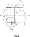
Figure 2 is a section view of a spigot according to the invention; -
Figure 3 is an isometric view of a connector according to the invention; -
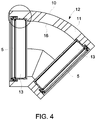
Figure 4 is a section view of the connector; -
Figure 5 is a detail view of the section of the connector; -
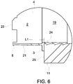
Figure 6 is a detail view of the section of the spigot. - Referring to
figure 1 , the present invention relates to asystem 1 for connecting twoventilation duct sections 12 to each other in end-to-end abutting relation to form a continuous conduit for the passage of air between said sections. Thesystem 1 comprises a resilientlydeformable spigot 4 having alip 8, thespigot 4 being mountable to oneventilation duct section 12 to extend from an open end thereof, and ahub 5 comprising aramp 15 mountable within an open end of the otherventilation duct section 12. The arrangement being such that when thespigot 4 and thehub 5 are mounted to respectiveventilation duct sections 12, thespigot 4 is insertable into thehub 5 so that thelip 8 and theramp 15 cooperate to resiliently compress thespigot 4. Further insertion of thespigot 4 into thehub 5 causes thelip 8 to pass beyond theramp 15 so that thespigot 4 expands to locate thelip 8 behind theramp 15 and connect theventilation duct sections 12 together. - Referring to
Figure 2 , one end of aduct section 12 is shown in cross section. The illustratedduct section 12 is a straight section, that is, it extends along a straight central axis A-A. Other shape sections are envisaged and may include for example, tee-shape sections, bend pieces and plenums. Regardless of the section geometry,duct sections 12 are formed of a hollow extendedbody 11 that serves as the conduit for the passage of air. - It is also envisaged that
duct sections 12 may be any shape when viewed end on to the axis A-A. For example, theduct sections 12 may for example be circular, square or rectangular. Eachduct section 12 is open ended and aspigot 4 orhub 5 is mountable in the open end so that, when thespigot 4 and thehub 5 are mounted to respectiveventilation duct sections 12, thespigot 4 is insertable into thehub 5 to connectadjacent duct sections 12 together. -
Duct sections 12 can be provided with aspigot 4, ahub 5 or both. For example,duct sections 12 may comprise aspigot 4 at each end of theduct section 12. In such cases theduct sections 12 will include aconnector piece 10 that comprises ahub 5 at each end to connect with thespigots 4 ofadjacent duct sections 12. Aconnector 10 is shown infigure 3 . In another example, theduct sections 12 may comprise aspigot 4 at one end of the duct and ahub 5 at the other. In this example, the sections are orientated so that aspigot 4 end faces ahub 5 end so that the sections can be connected end to end,hub 5 to spigot 4. -
Figure 3 shows aconnector 10 piece. Theconnector piece 10 is aduct section 12 with ahub 5 mounted at each end of theduct section 12. Theconnecter 10 is provided to connect twoduct sections 12 together which have aspigot 4 at either end. The illustratedconnector 10 has an axis that extends through an angle so that connectedduct sections 12 extend in different directions. However,connectors 10 according to the invention are not limited in this way and the axis may take any path that is required, for example theconnector 10 could equally have a straight axis to connectduct sections 12 along a straight path. -
Figures 4 and5 show ahub 5 mounted within aduct section 12 of aconnector 10. It can be seen that eachhub 5 comprises aninsert 13 shaped to fit into an open end of thebody 11 of theduct section 12. Theinserts 13 are the same shape as theduct section 12 when viewed end on to its axis and are sized so that they fit tightly around the perimeter of itsinner surface 16. Theinserts 13 extend axially into theduct section 12 to define an overlap region into which aspigot 4 of anadjacent duct section 12 is fitted. Theinsert 13 may comprisebarb elements 40 depending from itsouter surface 20 to grip theinner surface 16 of thebody 11 of theduct section 12 and retain it therein. - The
hubs 5 have aleading edge 14 which is disposed adjacent the opening and which lies substantially flush with theinner surface 16 of the duct so that it does not obstruct thespigot 4 as it is being inserted into thehub 5. - The
hub 5 inserts 13 comprise aramp section 15 that extends into the overlap region. Theramp section 15 provides an inclined surface in the opening of theduct section 12 that gradually extends away from theduct section 12 body's 11inner surface 16 with distance along the central axis. The inclined surface leads up to an innerperipheral edge 17 of thehub 5 where theramp section 15 terminates. Aback surface 18 of thehub 5 depends from the innerperipheral edge 17 and extends obliquely to theinner surface 16. - Referring to
figures 2 and6 , aspigot 4 is shown mounted in an open end of aduct section 12. Thespigot 4 comprises a mountingportion 19 which fits into the end thebody 11 of the duct. The mountingportion 19 is the same shape as theduct section 12 when viewed end on to its axis and is sized so that it fits tightly around the perimeter of the duct section's 12inner surface 16. The mountingportion 19 extends axially into theduct section 12 and may comprisebarb elements 24 that extend from itsouter surface 21 to grip theinner surface 16 of thebody 11 of theduct section 12 and retain it thereto. - A remaining
portion 2 of thespigot 4 configured to be inserted into thehub 5 extends from the open end of theduct section 12 about the perimeter of the mountingportion 19 to aleading edge 22. The mountingportion 19 is separated from the remainingportion 2 by aradially extending flange 3 provided to seat against anend face 25 of aduct section 12 in which thespigot 4 is inserted. Therefore thespigot 4 is easily mountable into an open end of aduct section 12 by simply inserting thespigot 4 up to theradially extending flange 3. Theradially extending flange 3 also ensures that thespigot 4 is mounted concentrically with theduct section 12. - The
spigot 4 may extend parallel to the mountingportion 19, or it may extend obliquely thereto so that the outer perimeter at theleading edge 22 is smaller than the perimeter of the opening of theduct sections 12. This allows the leadingedge 22 to be more easily located in thehub 5 of anadjacent duct section 12. It shall be appreciated that although the outer perimeter of the leadingedge 22 of thespigot 4 may be smaller than the perimeter of the opening of theduct sections 12, it must remain large enough that the leadingedge 22 comes into contact with theramp section 15 of thehub 5 for reasons that will become apparent below. - As shown most clearly in
figures 2 and6 , thespigot 4 comprises a series of spacedprotrusions 36 that extend axially from the leadingedge 22. In the illustrated embodiment, the spacedprotrusions 36 are evenly spaced around the perimeter of the leadingedge 22 so that it is castellated in appearance. The outermost edges 23 of the spacedprotrusions 36 comprise alip 8 on theouter surface 21. Theprotrusions 36 are resiliently deformable to allow them to be compressed as it is inserted into thehub 5. The wall thickness of thespigot 4 may also be reduced around the leadingedge 22 to increase the deformability of theprotrusions 36. - In another unillustrated embodiment, the spaced
protrusions 36 are omitted and thelip 8 is instead provided around the perimeter of the leadingedge 22. In such an embodiment thespigot 4 comprises a number of evenly spaced kerf cuts made axially through thespigot 4 to allow thespigot 4 to be compressed as it is inserted into thehub 5. - When two
duct sections 12 are connected, the ducts are axially aligned and thespigot 4 mounted to oneduct section 12 is inserted into thehub 5 mounted to anadjacent duct section 12. The leadingedge 22 of thespigot 4 passes over the leadingedge 14 of thehub 5 and thespigot lip 8 comes into contact with theramp section 15 of thehub 5 so that the insertion of thespigot 4 causes the leadingedge 14 of thespigot 4 to be compressed inwards by the inclined surface of theramp section 15. Further insertion of thespigot 4 into thehub 5 causes thelip 8 to pass beyond theramp section 15 so that thespigot 4 expands to locate thelip 8 behind the innerperipheral edge 17 of theramp section 15. Thelip 8 abuts against theback surface 18 of thehub 5 so that thespigot 4 is retained in thehub 5 and the twoduct sections 12 are connected together. The action of thespigot 4lip 8 passing over the innerperipheral edge 17 of thehub 5 creates an audible click which signifies that the twoduct sections 12 have been successfully connected. With the twoduct sections 12 connected together their end faces 25 abut, as shown infigure 1 . - A degree of compression in the
spigot 4 remains after thehub 5 and thespigot 4 have been connected. The back surface of theinsert 18 is angled such that the compressive force exerted by thehub 5 on thespigot 4 has an axial component that draws the twoduct sections 12 together and locks them in place. - The axial length Li of the remaining
portion 2 of thespigot 4 is marginally less than the axial distance L2 (figure 5 ) between theend face 25 of theadjacent duct section 12 and the innerperipheral edge 17 ofhub 5. Therefore, when thespigot 4 is received in thehub 5 with thelip 8 located behind theramp section 15, theduct sections 12 are squeezed together in end-to-end abutting relation to maintain a high level of thermal resistance. - A particular advantage of this system of connecting
duct sections 12 is that it is reversible. In other words, two connectedadjacent duct sections 12 can be pulled apart on application of sufficient force. This will cause thelip 8 of thespigot 4 to be displaced towards theduct section 12 axis so that it can pass back over theedge 17 of thehub 5. - As best shown in
figure 5 , a sealingmember 26 is provided around the perimeter of the leadingedge 14 of thehub 5 so that the connection made betweenadjacent duct sections 12 is air tight. The sealingmember 26 is a flipper seal, that is, it comprises a resilientlydeformable flange section 27 which upstands from theinsert 13 to extend into the opening of theduct section 12. Whenduct sections 12 are connected together, the leadingedge 22 of thespigot 4 displaces theflange section 27 and atip 28 of theflange section 27 contacts theouter surface 21 of thespigot 4 to make the connection airtight. - The sealing
member 26 further comprises adomed section 37. Thedomed section 37 is disposed closer to the leadingedge 14 of thehub 5 than theflange section 27 so that thespigot 4 first contacts thedomed section 37 on insertion into thehub 5. Thedomed section 37 presents a rounded surface which assists in smoothly guiding the leading edge of the spigot toward theramp section 15. - It will be appreciated that the sealing
member 26 negates the need for duct tape and sealant and therefore makes the assembly ofduct sections 12 easier than conventional systems. - In the illustrated embodiment the sealing
member 26 is attached to theinsert 13 by a retainingelement 29 that is shaped to insert over the sealingmember 26 where it contacts theinsert 13. The sealingmember 26 comprises abase part 30 and theinsert 13 comprises arecess 31 adjacent the leadingedge 14 to accommodate thebase part 30 of the sealingmember 26. The sealingmember 26 has an innerbevelled edge 32, which locates under a corresponding edge of therecess 31 in theinsert 13, and an outer bevelled edge 33, which locates under the retainingelement 29. Specifically, a retainingwall 35 of the retainingelement 29 extends into the opening to overlap the outer bevelled edge 33 of the sealingmember 26. Therefore the sealingmember 26 is locked between the retainingelement 29 and theinsert 13. - The wall thickness of the
duct section 12 is reduced at the opening to enlarge the opening. This provides a gap between theinsert 13 and theinner surface 16 of theduct section 12 into which aportion 34 of the retainingelement 29 can be inserted when thehub 5 is assembled. Saidportion 34 of the retainingelement 29 extends around theinner surface 16 of the opening between theduct section 12 and theinsert 13 and is tightly fitted to retain the retainingelement 29 in theduct section 12. In the illustrated embodiment saidportion 34 further comprisesribs 38 arranged around its inner surface that locate incorresponding grooves 39 in theouter surface 20 of theinsert 13 when the retainingelement 29 is fitted between theinsert 13 and theduct section 12. Theribs 38 help keep the retainingelement 29 located within theduct section 12. - The
body 11 of eachduct section 12 is manufactured from expanded polystyrene foam with a graphite additive. This material has a minimum density of 25 kg/m3 and maximum thermal conductivity of 0.3 W/mK such that at 20mm thickness, the insulation material forming the duct wall has a minimum thermal resistance of 0.666 m2K/W. Therefore, theduct section body 11 is formed from insulation material and does not require an additional insulating sleeve or jacket.
Claims (12)
- A system (1) for connecting two ventilation duct sections (12) to each other in end-to-end abutting relation to form a continuous conduit for the passage of air between said sections, the system comprising a resiliently deformable spigot (4) having an outer surface (21), a leading edge (22), and an outwardly directed lip (8) formed at said leading edge, the spigot being mountable to one ventilation duct section (12) to extend from an open end thereof, and a hub (5) mountable within an open end of the other ventilation duct section (12), the hub comprising a leading edge (14), an inner peripheral edge (17), and a ramp (15) comprising an inwardly directed inclined surface leading up to said inner peripheral edge (17), wherein a sealing member (26) is mounted to said hub around the perimeter of the leading edge (14) of the hub (5), the sealing member (26) configured to form a seal against the outer surface (21) of the spigot (4) when the spigot (4) is inserted into the hub (5), the arrangement being such that when the spigot and the hub are mounted to respective ventilation duct sections and the spigot is inserted into the hub, the sealing member (26) contacts the outer surface (21) of the spigot before the lip (8) cooperates with the inwardly directed inclined surface of the ramp (15) to resiliently compress the spigot, further insertion of the spigot into the hub causing the lip (8) to pass beyond the ramp (15) so that the spigot expands to locate the lip behind the ramp and connect the ventilation duct sections together.
- A system according to claim 1, wherein a series of spaced protrusions (36) extend from the leading edge of the spigot, the lip being formed at a tip of each protrusion.
- A system according to any preceding claim, comprising a recess (31) in the hub to receive the sealing member.
- A system according to claim 3, comprising a retaining element (29) attachable to the hub to retain the sealing member in the recess.
- A system according to any preceding claim, wherein the sealing member comprises a domed section (37) to make initial contact with the spigot when the spigot is inserted into the hub and, a flange section (27) that is deflected by the spigot on further insertion of the spigot into the hub.
- A system according to any preceding claim, wherein the spigot has a mounting portion (19) configured to extend into a ventilation duct section to mount the spigot thereto.
- A system according to claim 6, wherein said mounting portion (19) is separated from a remaining portion (2) of the spigot that is configured to be inserted into the hub by a radially extending flange (3) that seats against an end face of a ventilation duct section into which said portion extends.
- A system according to claim 6 or 7, wherein said mounting portion (19) comprises barb elements (24) to engage a ventilation duct section in which said mounting portion extends.
- A system according to any preceding claim, wherein the hub has barb elements (40) to engage a ventilation duct section in which said hub is mountable.
- A system according to any preceding claim wherein the spigot and the hub are configured so that, when the spigot is received in the hub with the lip located behind the ramp, the duct sections are squeezed together in end-to-end abutting relation.
- An arrangement comprising a first ventilation duct section (12), a second ventilation duct section (12) and a system (1) for connecting the two ventilation duct sections (12) to each other in end-to-end abutting relation to form a continuous conduit for the passage of air between said sections (12), the system being according to any one of claims 1-10, the spigot being mounted so as to extend from an open end of the first ventilation duct section, the second ventilation duct section having the hub mounted within an open end of said second ventilation duct section.
- The arrangement according to claim 11, the duct sections (12) being made from expanded polystyrene foam.
Priority Applications (1)
| Application Number | Priority Date | Filing Date | Title |
|---|---|---|---|
| PL17714529T PL3436731T3 (en) | 2016-03-31 | 2017-03-22 | A system for connecting two ventiliation duct sections to each other |
Applications Claiming Priority (2)
| Application Number | Priority Date | Filing Date | Title |
|---|---|---|---|
| GB1605425.6A GB2548867A (en) | 2016-03-31 | 2016-03-31 | A system for connecting two ventilation duct sections to each other |
| PCT/GB2017/050806 WO2017168123A1 (en) | 2016-03-31 | 2017-03-22 | A system for connecting two ventiliation duct sections to each other |
Publications (2)
| Publication Number | Publication Date |
|---|---|
| EP3436731A1 EP3436731A1 (en) | 2019-02-06 |
| EP3436731B1 true EP3436731B1 (en) | 2020-02-12 |
Family
ID=58455350
Family Applications (1)
| Application Number | Title | Priority Date | Filing Date |
|---|---|---|---|
| EP17714529.9A Active EP3436731B1 (en) | 2016-03-31 | 2017-03-22 | A system for connecting two ventiliation duct sections to each other |
Country Status (6)
| Country | Link |
|---|---|
| EP (1) | EP3436731B1 (en) |
| AU (1) | AU2017240275B2 (en) |
| ES (1) | ES2778832T3 (en) |
| GB (1) | GB2548867A (en) |
| PL (1) | PL3436731T3 (en) |
| WO (1) | WO2017168123A1 (en) |
Family Cites Families (7)
| Publication number | Priority date | Publication date | Assignee | Title |
|---|---|---|---|---|
| FR2626660B1 (en) * | 1988-02-02 | 1990-07-06 | Hutchinson Sa | ASSEMBLY DEVICE FOR A HEAT EXCHANGER / TUBULAR CONNECTION ASSEMBLY |
| FR2812371B1 (en) * | 2000-07-28 | 2003-06-27 | Hutchinson | WATERPROOF CONNECTION SYSTEM BETWEEN A CONDUIT AND A BULB TUBULAR END |
| US7404686B2 (en) * | 2005-04-26 | 2008-07-29 | Peter Volum | Snap fitting for joining component parts of an article of assembly |
| US7393021B1 (en) * | 2005-11-15 | 2008-07-01 | M. Zack Lukjan | HVAC duct system |
| GB2452038B (en) * | 2007-08-20 | 2012-05-02 | Wavin Bv | Push-fit pipe fitting system |
| WO2011066612A1 (en) * | 2009-12-01 | 2011-06-09 | Connect Air Manufacturing Pty Ltd | Ducted heating, ventilation, and air conditioning (hvac) component and system improvements |
| GB2510175B (en) * | 2013-01-28 | 2017-10-04 | Verplas Ltd | Ventilation duct coupling |
-
2016
- 2016-03-31 GB GB1605425.6A patent/GB2548867A/en not_active Withdrawn
-
2017
- 2017-03-22 ES ES17714529T patent/ES2778832T3/en active Active
- 2017-03-22 WO PCT/GB2017/050806 patent/WO2017168123A1/en not_active Ceased
- 2017-03-22 AU AU2017240275A patent/AU2017240275B2/en active Active
- 2017-03-22 PL PL17714529T patent/PL3436731T3/en unknown
- 2017-03-22 EP EP17714529.9A patent/EP3436731B1/en active Active
Non-Patent Citations (1)
| Title |
|---|
| None * |
Also Published As
| Publication number | Publication date |
|---|---|
| PL3436731T3 (en) | 2020-10-05 |
| NZ746740A (en) | 2024-02-23 |
| AU2017240275B2 (en) | 2021-04-15 |
| EP3436731A1 (en) | 2019-02-06 |
| ES2778832T3 (en) | 2020-08-12 |
| AU2017240275A1 (en) | 2018-10-18 |
| WO2017168123A1 (en) | 2017-10-05 |
| GB2548867A (en) | 2017-10-04 |
Similar Documents
| Publication | Publication Date | Title |
|---|---|---|
| US9461452B2 (en) | Cable glands | |
| US4457544A (en) | Connector for flexible electrical conduit | |
| US6256948B1 (en) | Fire-resistant passage for lines | |
| EP4118386B1 (en) | Fitting assembly for a flexible duct | |
| EP2759779B1 (en) | Ventilation duct coupling and method of manufacturing thereof | |
| US9279522B2 (en) | Sleeve lock assembly | |
| JP4791428B2 (en) | Duct connection structure | |
| EP4667805A2 (en) | Pipe assembly insulation and vapor barrier | |
| EP2784404B1 (en) | Ventilation ducting connector | |
| JP4863986B2 (en) | Through-duct and hollow wall duct structure using the through-duct | |
| US20050109415A1 (en) | Two piece air duct section | |
| AU2017240275B2 (en) | A system for connecting two ventilation duct sections to each other | |
| JP6978961B2 (en) | Fireproof structure, fireproof equipment and closing members | |
| JP7320577B2 (en) | Refractories and closures | |
| US11480273B2 (en) | Fluid coupling | |
| WO2016089290A1 (en) | Fire stop | |
| EP3736504B1 (en) | Pipe protecting support and air conditioner | |
| JP6798773B2 (en) | Pipe connection structure | |
| JP7320576B2 (en) | Refractories and closures | |
| US20050155209A1 (en) | Positive pipe interlock | |
| US20120061388A1 (en) | Pipe and Pipe Joint Covering Apparatus | |
| US20210246603A1 (en) | Duct connector assembly | |
| US20210010710A1 (en) | System of Couplers for Connecting Flexible Ducting of Forced Air Systems | |
| JP7705766B2 (en) | Duct Connection Device | |
| EP4549796B1 (en) | Connector for coupling a corrugated duct to a ducting component, partial assembly comprising said connector and assembly comprising a corrugated duct connected to a ducting component by means of said connector |
Legal Events
| Date | Code | Title | Description |
|---|---|---|---|
| STAA | Information on the status of an ep patent application or granted ep patent |
Free format text: STATUS: UNKNOWN |
|
| STAA | Information on the status of an ep patent application or granted ep patent |
Free format text: STATUS: THE INTERNATIONAL PUBLICATION HAS BEEN MADE |
|
| PUAI | Public reference made under article 153(3) epc to a published international application that has entered the european phase |
Free format text: ORIGINAL CODE: 0009012 |
|
| STAA | Information on the status of an ep patent application or granted ep patent |
Free format text: STATUS: REQUEST FOR EXAMINATION WAS MADE |
|
| 17P | Request for examination filed |
Effective date: 20180925 |
|
| AK | Designated contracting states |
Kind code of ref document: A1 Designated state(s): AL AT BE BG CH CY CZ DE DK EE ES FI FR GB GR HR HU IE IS IT LI LT LU LV MC MK MT NL NO PL PT RO RS SE SI SK SM TR |
|
| AX | Request for extension of the european patent |
Extension state: BA ME |
|
| DAV | Request for validation of the european patent (deleted) | ||
| DAX | Request for extension of the european patent (deleted) | ||
| GRAP | Despatch of communication of intention to grant a patent |
Free format text: ORIGINAL CODE: EPIDOSNIGR1 |
|
| STAA | Information on the status of an ep patent application or granted ep patent |
Free format text: STATUS: GRANT OF PATENT IS INTENDED |
|
| INTG | Intention to grant announced |
Effective date: 20191128 |
|
| GRAS | Grant fee paid |
Free format text: ORIGINAL CODE: EPIDOSNIGR3 |
|
| GRAA | (expected) grant |
Free format text: ORIGINAL CODE: 0009210 |
|
| STAA | Information on the status of an ep patent application or granted ep patent |
Free format text: STATUS: THE PATENT HAS BEEN GRANTED |
|
| AK | Designated contracting states |
Kind code of ref document: B1 Designated state(s): AL AT BE BG CH CY CZ DE DK EE ES FI FR GB GR HR HU IE IS IT LI LT LU LV MC MK MT NL NO PL PT RO RS SE SI SK SM TR |
|
| REG | Reference to a national code |
Ref country code: GB Ref legal event code: FG4D |
|
| REG | Reference to a national code |
Ref country code: CH Ref legal event code: EP |
|
| REG | Reference to a national code |
Ref country code: AT Ref legal event code: REF Ref document number: 1232555 Country of ref document: AT Kind code of ref document: T Effective date: 20200215 |
|
| REG | Reference to a national code |
Ref country code: DE Ref legal event code: R096 Ref document number: 602017011654 Country of ref document: DE |
|
| REG | Reference to a national code |
Ref country code: IE Ref legal event code: FG4D |
|
| REG | Reference to a national code |
Ref country code: SE Ref legal event code: TRGR |
|
| REG | Reference to a national code |
Ref country code: NL Ref legal event code: FP |
|
| PG25 | Lapsed in a contracting state [announced via postgrant information from national office to epo] |
Ref country code: RS Free format text: LAPSE BECAUSE OF FAILURE TO SUBMIT A TRANSLATION OF THE DESCRIPTION OR TO PAY THE FEE WITHIN THE PRESCRIBED TIME-LIMIT Effective date: 20200212 Ref country code: FI Free format text: LAPSE BECAUSE OF FAILURE TO SUBMIT A TRANSLATION OF THE DESCRIPTION OR TO PAY THE FEE WITHIN THE PRESCRIBED TIME-LIMIT Effective date: 20200212 Ref country code: NO Free format text: LAPSE BECAUSE OF FAILURE TO SUBMIT A TRANSLATION OF THE DESCRIPTION OR TO PAY THE FEE WITHIN THE PRESCRIBED TIME-LIMIT Effective date: 20200512 |
|
| REG | Reference to a national code |
Ref country code: LT Ref legal event code: MG4D |
|
| REG | Reference to a national code |
Ref country code: ES Ref legal event code: FG2A Ref document number: 2778832 Country of ref document: ES Kind code of ref document: T3 Effective date: 20200812 |
|
| PG25 | Lapsed in a contracting state [announced via postgrant information from national office to epo] |
Ref country code: LV Free format text: LAPSE BECAUSE OF FAILURE TO SUBMIT A TRANSLATION OF THE DESCRIPTION OR TO PAY THE FEE WITHIN THE PRESCRIBED TIME-LIMIT Effective date: 20200212 Ref country code: IS Free format text: LAPSE BECAUSE OF FAILURE TO SUBMIT A TRANSLATION OF THE DESCRIPTION OR TO PAY THE FEE WITHIN THE PRESCRIBED TIME-LIMIT Effective date: 20200612 Ref country code: BG Free format text: LAPSE BECAUSE OF FAILURE TO SUBMIT A TRANSLATION OF THE DESCRIPTION OR TO PAY THE FEE WITHIN THE PRESCRIBED TIME-LIMIT Effective date: 20200512 Ref country code: GR Free format text: LAPSE BECAUSE OF FAILURE TO SUBMIT A TRANSLATION OF THE DESCRIPTION OR TO PAY THE FEE WITHIN THE PRESCRIBED TIME-LIMIT Effective date: 20200513 Ref country code: HR Free format text: LAPSE BECAUSE OF FAILURE TO SUBMIT A TRANSLATION OF THE DESCRIPTION OR TO PAY THE FEE WITHIN THE PRESCRIBED TIME-LIMIT Effective date: 20200212 |
|
| REG | Reference to a national code |
Ref country code: DE Ref legal event code: R082 Ref document number: 602017011654 Country of ref document: DE Representative=s name: VENNER SHIPLEY GERMANY LLP, DE Ref country code: DE Ref legal event code: R082 Ref document number: 602017011654 Country of ref document: DE Representative=s name: VENNER SHIPLEY LLP, DE |
|
| PG25 | Lapsed in a contracting state [announced via postgrant information from national office to epo] |
Ref country code: SK Free format text: LAPSE BECAUSE OF FAILURE TO SUBMIT A TRANSLATION OF THE DESCRIPTION OR TO PAY THE FEE WITHIN THE PRESCRIBED TIME-LIMIT Effective date: 20200212 Ref country code: RO Free format text: LAPSE BECAUSE OF FAILURE TO SUBMIT A TRANSLATION OF THE DESCRIPTION OR TO PAY THE FEE WITHIN THE PRESCRIBED TIME-LIMIT Effective date: 20200212 Ref country code: EE Free format text: LAPSE BECAUSE OF FAILURE TO SUBMIT A TRANSLATION OF THE DESCRIPTION OR TO PAY THE FEE WITHIN THE PRESCRIBED TIME-LIMIT Effective date: 20200212 Ref country code: SM Free format text: LAPSE BECAUSE OF FAILURE TO SUBMIT A TRANSLATION OF THE DESCRIPTION OR TO PAY THE FEE WITHIN THE PRESCRIBED TIME-LIMIT Effective date: 20200212 Ref country code: DK Free format text: LAPSE BECAUSE OF FAILURE TO SUBMIT A TRANSLATION OF THE DESCRIPTION OR TO PAY THE FEE WITHIN THE PRESCRIBED TIME-LIMIT Effective date: 20200212 Ref country code: LT Free format text: LAPSE BECAUSE OF FAILURE TO SUBMIT A TRANSLATION OF THE DESCRIPTION OR TO PAY THE FEE WITHIN THE PRESCRIBED TIME-LIMIT Effective date: 20200212 Ref country code: PT Free format text: LAPSE BECAUSE OF FAILURE TO SUBMIT A TRANSLATION OF THE DESCRIPTION OR TO PAY THE FEE WITHIN THE PRESCRIBED TIME-LIMIT Effective date: 20200705 |
|
| REG | Reference to a national code |
Ref country code: CH Ref legal event code: PL |
|
| REG | Reference to a national code |
Ref country code: DE Ref legal event code: R097 Ref document number: 602017011654 Country of ref document: DE |
|
| REG | Reference to a national code |
Ref country code: AT Ref legal event code: MK05 Ref document number: 1232555 Country of ref document: AT Kind code of ref document: T Effective date: 20200212 |
|
| PG25 | Lapsed in a contracting state [announced via postgrant information from national office to epo] |
Ref country code: MC Free format text: LAPSE BECAUSE OF FAILURE TO SUBMIT A TRANSLATION OF THE DESCRIPTION OR TO PAY THE FEE WITHIN THE PRESCRIBED TIME-LIMIT Effective date: 20200212 |
|
| PLBE | No opposition filed within time limit |
Free format text: ORIGINAL CODE: 0009261 |
|
| STAA | Information on the status of an ep patent application or granted ep patent |
Free format text: STATUS: NO OPPOSITION FILED WITHIN TIME LIMIT |
|
| PG25 | Lapsed in a contracting state [announced via postgrant information from national office to epo] |
Ref country code: LU Free format text: LAPSE BECAUSE OF NON-PAYMENT OF DUE FEES Effective date: 20200322 |
|
| 26N | No opposition filed |
Effective date: 20201113 |
|
| PG25 | Lapsed in a contracting state [announced via postgrant information from national office to epo] |
Ref country code: AT Free format text: LAPSE BECAUSE OF FAILURE TO SUBMIT A TRANSLATION OF THE DESCRIPTION OR TO PAY THE FEE WITHIN THE PRESCRIBED TIME-LIMIT Effective date: 20200212 Ref country code: LI Free format text: LAPSE BECAUSE OF NON-PAYMENT OF DUE FEES Effective date: 20200331 Ref country code: CH Free format text: LAPSE BECAUSE OF NON-PAYMENT OF DUE FEES Effective date: 20200331 |
|
| PG25 | Lapsed in a contracting state [announced via postgrant information from national office to epo] |
Ref country code: SI Free format text: LAPSE BECAUSE OF FAILURE TO SUBMIT A TRANSLATION OF THE DESCRIPTION OR TO PAY THE FEE WITHIN THE PRESCRIBED TIME-LIMIT Effective date: 20200212 |
|
| PG25 | Lapsed in a contracting state [announced via postgrant information from national office to epo] |
Ref country code: TR Free format text: LAPSE BECAUSE OF FAILURE TO SUBMIT A TRANSLATION OF THE DESCRIPTION OR TO PAY THE FEE WITHIN THE PRESCRIBED TIME-LIMIT Effective date: 20200212 Ref country code: MT Free format text: LAPSE BECAUSE OF FAILURE TO SUBMIT A TRANSLATION OF THE DESCRIPTION OR TO PAY THE FEE WITHIN THE PRESCRIBED TIME-LIMIT Effective date: 20200212 Ref country code: CY Free format text: LAPSE BECAUSE OF FAILURE TO SUBMIT A TRANSLATION OF THE DESCRIPTION OR TO PAY THE FEE WITHIN THE PRESCRIBED TIME-LIMIT Effective date: 20200212 |
|
| PG25 | Lapsed in a contracting state [announced via postgrant information from national office to epo] |
Ref country code: MK Free format text: LAPSE BECAUSE OF FAILURE TO SUBMIT A TRANSLATION OF THE DESCRIPTION OR TO PAY THE FEE WITHIN THE PRESCRIBED TIME-LIMIT Effective date: 20200212 Ref country code: AL Free format text: LAPSE BECAUSE OF FAILURE TO SUBMIT A TRANSLATION OF THE DESCRIPTION OR TO PAY THE FEE WITHIN THE PRESCRIBED TIME-LIMIT Effective date: 20200212 |
|
| P01 | Opt-out of the competence of the unified patent court (upc) registered |
Effective date: 20230530 |
|
| P02 | Opt-out of the competence of the unified patent court (upc) changed |
Effective date: 20230530 |
|
| PGFP | Annual fee paid to national office [announced via postgrant information from national office to epo] |
Ref country code: SE Payment date: 20250321 Year of fee payment: 9 |
|
| PGFP | Annual fee paid to national office [announced via postgrant information from national office to epo] |
Ref country code: DE Payment date: 20250319 Year of fee payment: 9 |
|
| PGFP | Annual fee paid to national office [announced via postgrant information from national office to epo] |
Ref country code: NL Payment date: 20250319 Year of fee payment: 9 |
|
| PGFP | Annual fee paid to national office [announced via postgrant information from national office to epo] |
Ref country code: BE Payment date: 20250319 Year of fee payment: 9 |
|
| PGFP | Annual fee paid to national office [announced via postgrant information from national office to epo] |
Ref country code: FR Payment date: 20250326 Year of fee payment: 9 Ref country code: PL Payment date: 20250218 Year of fee payment: 9 Ref country code: CZ Payment date: 20250317 Year of fee payment: 9 |
|
| PGFP | Annual fee paid to national office [announced via postgrant information from national office to epo] |
Ref country code: IT Payment date: 20250319 Year of fee payment: 9 |
|
| PGFP | Annual fee paid to national office [announced via postgrant information from national office to epo] |
Ref country code: ES Payment date: 20250429 Year of fee payment: 9 |
|
| PGFP | Annual fee paid to national office [announced via postgrant information from national office to epo] |
Ref country code: GB Payment date: 20260317 Year of fee payment: 10 |
|
| PGFP | Annual fee paid to national office [announced via postgrant information from national office to epo] |
Ref country code: IE Payment date: 20260319 Year of fee payment: 10 |