EP3436298B1 - Side to side roller tarp system - Google Patents
Side to side roller tarp system Download PDFInfo
- Publication number
- EP3436298B1 EP3436298B1 EP17776728.2A EP17776728A EP3436298B1 EP 3436298 B1 EP3436298 B1 EP 3436298B1 EP 17776728 A EP17776728 A EP 17776728A EP 3436298 B1 EP3436298 B1 EP 3436298B1
- Authority
- EP
- European Patent Office
- Prior art keywords
- tarp
- pivot arm
- spool
- coupled
- assembly
- Prior art date
- Legal status (The legal status is an assumption and is not a legal conclusion. Google has not performed a legal analysis and makes no representation as to the accuracy of the status listed.)
- Active
Links
Images




Classifications
-
- B—PERFORMING OPERATIONS; TRANSPORTING
- B60—VEHICLES IN GENERAL
- B60J—WINDOWS, WINDSCREENS, NON-FIXED ROOFS, DOORS, OR SIMILAR DEVICES FOR VEHICLES; REMOVABLE EXTERNAL PROTECTIVE COVERINGS SPECIALLY ADAPTED FOR VEHICLES
- B60J7/00—Non-fixed roofs; Roofs with movable panels, e.g. rotary sunroofs
- B60J7/08—Non-fixed roofs; Roofs with movable panels, e.g. rotary sunroofs of non-sliding type, i.e. movable or removable roofs or panels, e.g. let-down tops or roofs capable of being easily detached or of assuming a collapsed or inoperative position
- B60J7/085—Non-fixed roofs; Roofs with movable panels, e.g. rotary sunroofs of non-sliding type, i.e. movable or removable roofs or panels, e.g. let-down tops or roofs capable of being easily detached or of assuming a collapsed or inoperative position winding up, e.g. for utility vehicles
-
- B—PERFORMING OPERATIONS; TRANSPORTING
- B60—VEHICLES IN GENERAL
- B60J—WINDOWS, WINDSCREENS, NON-FIXED ROOFS, DOORS, OR SIMILAR DEVICES FOR VEHICLES; REMOVABLE EXTERNAL PROTECTIVE COVERINGS SPECIALLY ADAPTED FOR VEHICLES
- B60J7/00—Non-fixed roofs; Roofs with movable panels, e.g. rotary sunroofs
- B60J7/02—Non-fixed roofs; Roofs with movable panels, e.g. rotary sunroofs of sliding type, e.g. comprising guide shoes
- B60J7/06—Non-fixed roofs; Roofs with movable panels, e.g. rotary sunroofs of sliding type, e.g. comprising guide shoes with non-rigid element or elements
- B60J7/061—Non-fixed roofs; Roofs with movable panels, e.g. rotary sunroofs of sliding type, e.g. comprising guide shoes with non-rigid element or elements sliding and folding
- B60J7/064—Non-fixed roofs; Roofs with movable panels, e.g. rotary sunroofs of sliding type, e.g. comprising guide shoes with non-rigid element or elements sliding and folding using folding arms sliding in longitudinal tracks for supporting the soft roof
- B60J7/065—Non-fixed roofs; Roofs with movable panels, e.g. rotary sunroofs of sliding type, e.g. comprising guide shoes with non-rigid element or elements sliding and folding using folding arms sliding in longitudinal tracks for supporting the soft roof for utility vehicles
-
- B—PERFORMING OPERATIONS; TRANSPORTING
- B60—VEHICLES IN GENERAL
- B60P—VEHICLES ADAPTED FOR LOAD TRANSPORTATION OR TO TRANSPORT, TO CARRY, OR TO COMPRISE SPECIAL LOADS OR OBJECTS
- B60P7/00—Securing or covering of load on vehicles
- B60P7/02—Covering of load
- B60P7/04—Covering of load by tarpaulins or like flexible members
-
- B—PERFORMING OPERATIONS; TRANSPORTING
- B60—VEHICLES IN GENERAL
- B60P—VEHICLES ADAPTED FOR LOAD TRANSPORTATION OR TO TRANSPORT, TO CARRY, OR TO COMPRISE SPECIAL LOADS OR OBJECTS
- B60P7/00—Securing or covering of load on vehicles
- B60P7/06—Securing of load
- B60P7/08—Securing to the vehicle floor or sides
- B60P7/0807—Attachment points
-
- B—PERFORMING OPERATIONS; TRANSPORTING
- B61—RAILWAYS
- B61D—BODY DETAILS OR KINDS OF RAILWAY VEHICLES
- B61D39/00—Wagon or like covers; Tarpaulins; Movable or foldable roofs
-
- F—MECHANICAL ENGINEERING; LIGHTING; HEATING; WEAPONS; BLASTING
- F16—ENGINEERING ELEMENTS AND UNITS; GENERAL MEASURES FOR PRODUCING AND MAINTAINING EFFECTIVE FUNCTIONING OF MACHINES OR INSTALLATIONS; THERMAL INSULATION IN GENERAL
- F16H—GEARING
- F16H1/00—Toothed gearings for conveying rotary motion
- F16H1/28—Toothed gearings for conveying rotary motion with gears having orbital motion
- F16H1/46—Systems consisting of a plurality of gear trains each with orbital gears, i.e. systems having three or more central gears
-
- F—MECHANICAL ENGINEERING; LIGHTING; HEATING; WEAPONS; BLASTING
- F16—ENGINEERING ELEMENTS AND UNITS; GENERAL MEASURES FOR PRODUCING AND MAINTAINING EFFECTIVE FUNCTIONING OF MACHINES OR INSTALLATIONS; THERMAL INSULATION IN GENERAL
- F16H—GEARING
- F16H48/00—Differential gearings
- F16H48/06—Differential gearings with gears having orbital motion
- F16H48/10—Differential gearings with gears having orbital motion with orbital spur gears
- F16H48/11—Differential gearings with gears having orbital motion with orbital spur gears having intermeshing planet gears
Definitions
- the present invention relates to a roller tarp system for truck beds, and more particularly, to a roller tarp system having an internal drive assembly for selectively covering and uncovering the truck bed of a truck.
- truck cover or tarp system to prevent the wind from blowing load particles off the truck bed.
- Various apparatus have been devised for covering a truck bed and load. Some such apparatus include an external motor assembly for selectively winding a roller and tarp for covering the truck bed.
- An effective cover should be one which is easily operated by the truck driver so as to selectively cover and uncover the load in the truck bed from the convenient location of the truck cab.
- Current tarp systems commonly include a pair of arms pivotally mounted along opposing sides of the truck bed and each of which includes a base and an extension.
- a tarp roller is rotatably mounted between the extensions of the arms for supporting a tarp.
- An external motor assembly is typically mounted to one of the extensions and coupled to the tarp roller for selectively winding the roller and tarp and automatically covering and uncovering the truck bed.
- the external motor increases the overall width of the truck bed and complexity of the tarp system while also remaining exposed to the elements and damage by debris loaded into the truck bed.
- US 2014/265424 A1 relates to a tarp deploying apparatus including a radial arm with a proximal arm and a distal arm.
- a flexible inelastic limit element is provided between the proximal and distal arm to prevent them from crossing over center to an angle that would cause the apparatus to bind.
- WO 2015/175995 A1 discloses a rotatable awning assembly mounted on a side wall of a recreational vehicle.
- the awning assembly comprises two respective sets of first, second and third arms at each side of a rotating awning roller tube.
- the first arms are mounted to the side wall of the vehicle, and the second arms are pivotally connected to the first arms and are sized to be nested in a nested arrangement with the first and the third arms which are pivotally connected to opposite ends of the second arms and spaced from the first arms.
- the awning assembly further comprises an awning drive assembly including a motor and a drive for driving the roller tube with the motor integrated in the awning tube.
- a tarp system covering a truck bed comprises a first pivot arm assembly pivotaliy coupled to the truck bed and a second pivot arm assembly pivotaliy coupled to the truck bed and spaced from the first pivot arm assembly.
- a generally hollow tarp spool extends along a longitudinal axis between opposite first and second ends.
- the tarp spool is rotatably coupled between the first and second pivot arm assemblies and rotatably supporting a tarp cover.
- a drive assembly is housed within the tarp spool adjacent one of the first and second ends.
- the drive assembly is operatively coupled between one of the first and second pivot arm assemblies and the tarp spool for selectively rotating the tarp spool and actuating the tarp system between an open position uncovering the truck bed and a closed position covering the truck bed.
- the drive assembly includes a motor.
- Figures 1 and 2 show a roller tarp system 10 according to the present invention for covering and uncovering the bed or trailer 12 of a truck 14.
- the truck 14 includes the truck bed 12 having front and rear ends 16, 18 extending laterally between opposite first and second sidewalls 20, 22.
- the truck 14 and truck bed 12 may be a single axle, tandem axle, single or double trailer bed, open trailer bed or the like which have a bed with an open top which needs to be covered by a tarp system.
- the roller tarp system 10 is shown operatively coupled to the front and rear ends 16, 18 of the truck bed 12, commonly referred to as a side to side tarp system, for selective operation between an open position (shown in phantom) uncovering the truck bed 12 and a closed position (shown in solid) covering the truck bed 12.
- a side to side tarp system for selective operation between an open position (shown in phantom) uncovering the truck bed 12 and a closed position (shown in solid) covering the truck bed 12.
- the roller tarp system 10 may be operatively coupled to the first and second sidewalls 20, 22, front to back tarp system, without varying from the scope of the invention.
- the roller tarp system 10 includes a base plate 24 fixedly secured to each of the front end 16 and rear end 18 generally midway between the sidewalls 20, 22 for pivotally supporting the roller tarp system 10 between the open and closed positions.
- a pivot arm assembly 26, 28 is pivotally coupled to the base plate 24 by a fixed pivot post 30.
- Each pivot arm assembly 26, 28 includes an elongated lower pivot arm 32 extending between a first end pivotally coupled to the base plate 24 by pivot post 30 and an opposite second end and an elongated upper pivot arm 34 extending between a first end pivotally coupled to the second send of the lower pivot arm 32 by a fixed knuckle pivot 36 and an opposite second end.
- the roller tarp system 10 further includes a hollow, cylindrical tarp spool 38 extending longitudinally between and rotatably coupled to the second ends of each of the upper pivot arms 34 for rotatably spooling and supporting a tarp cover 40.
- the tarp cover 40 is generally made of flexible fabric, however, other like materials may be utilized without varying the scope of the invention.
- the base plate 24 includes at least one, but preferably a plurality of, first spiral torsion springs 42 for biasing the lower pivot arm 32 in the counterclockwise direction.
- first spiral torsion springs 42 for biasing the lower pivot arm 32 in the counterclockwise direction.
- one end of each spring 42 engages a groove or notch formed in the fixed pivot post 30 and an opposite end engages a locator pin on the lower pivot arm 32.
- second spiral torsion springs 44 are coupled between the lower pivot arm 32 and upper pivot arm 34 for biasing the upper pivot arm 34 in the counterclockwise direction.
- one end of each spring 44 engages a groove or notch formed in the knuckle pivot 36 and an opposite end engages a locator pin on the upper pivot arm 34.
- rotation of the upper pivot arm 34 relative to the lower pivot arm 32 is limited by the upper pivot arm 34 engaging a blocking pin 46 projecting from the distal end of the lower pivot arm 32 spaced from the knuckle pivot 36 as shown in Figures 2-4 .
- a first end of the tarp spool 38 is slidably and rotatably coupled to the second distal end of the upper pivot arm 34 of the pivot arm assembly 26 by a first bearing sleeve 48 to allow for both rotation of the tarp spool 38 and axial sliding of the tarp spool along axis A relative to the pivot arm assembly 26. That is, the bearing sleeve 48 allow for axial sliding movement of the tarp spool 38 during actuation between the open and closed positions to account for tolerance, bending, and/or synchronization of the pivotal movement between the pivot arm assemblies 26, 28 over the length of the truck bed 12.
- An opposite second end of the tarp spool 38 is operatively and rotatably coupled to the second distal end of the upper pivot arm 34 of the pivot arm assembly 28 by a drive assembly 50.
- the drive assembly 50 is housed internally within the hollow cylindrical tarp spool 38 so as to conceal the drive assembly 50 from the external elements, damage, and reduce the overall width of the tarp system.
- the drive assembly 50 comprises a first end fixedly secured to the distal second end of the upper pivot arm 34 and an opposite second end fixedly secured to the tarp spool 38.
- a second bearing sleeve 52 is fixedly secured to the tarp spool 38 and receives the drive assembly 50 therethrough to allow the tarp spool 38 to rotate around and relative to the drive assembly 50.
- the drive assembly 50 includes an electric DC motor 54 having a first end fixedly connected to the distal second end of the upper pivot arm 34.
- a motor output shaft 56 extends axial from the opposite second end of the motor 54 and is rotatably driven by the motor 54.
- a gear reduction assembly 58 is fixedly secured to the motor 54 and operatively coupled to the motor output shaft 56 for both reducing the output speed while multiplying the output torque of the drive assembly 50.
- An output drive shaft 60 extends axial from the gear reduction assembly 58 opposite the motor 54 and is rotatably driven by the motor 54 and gear reduction assembly 58.
- a drive hub 62 is fixedly coupled to the distal end of the output drive shaft 60 by fastener 64 for rotation therewith.
- the drive hub 62 is further fixedly secured to the tarp spool 38 by a plurality of fasteners 68 to transfer rotational movement of the output drive shaft 60 to rotational movement of the tarp spool 38.
- the drive hub 62 is disc-shaped and includes a center bore 68 for receiving the output drive shaft 60 therein.
- the center bore 68 includes an axial notch 70 formed therein and the output drive shaft 60 similarly includes an axial notch 72 formed therein.
- a generally rectangular shear key 74 is aligned with and seated in each of the notches 70, 72 to rotatably connect the output drive shaft 60 to the drive hub 62 and provide a safety feature of shearing in the event the torque on the drive hub 62 exceed the capability and torque specifications of the output drive shaft 60 and motor 54.
- the drive hub 62 further includes an outer peripheral surface having an axial slot 74 formed therein and the tarp spool 38 includes an axial protrusion 76 formed in its tube wall corresponding to the axial slot 74. The protrusion 76 is matingly received in the axial slot 74 to rotatably connect the drive hub 62 to the tarp spool 38 and fixedly secured by the fasteners 66.
- the keyed connection between the protrusion 76 on the tarp spool 38 and the slot 74 in the drive hub 62 transfer the rotational movement of the drive hub 62 to corresponding rotational movement of the tarp spool 38.
- a channel 78 formed on the backside of the axial protrusion 76 receives a plurality of spaced apart locking keys 80 to fixedly secure one edge of the tarp cover 40 to the tarp spool 38.
- the gear reduction assembly 58 is shown and discussed in more detail.
- the gear reduction assembly 58 or gear reducer, is operatively coupled between the motor output shaft 56 and the output drive shaft 60 to selectively reduce the speed while multiplying the torque of the output drive shaft 60 relative to the motor output shaft 56 for rotation of the tarp spool 38.
- the gear reduction assembly 58 includes a series of planetary gear sets, however it should be appreciate that one or more planetary gear sets may be used between the motor output shaft 56 and the output drive shaft 60 as desired for the rotation of the tarp spool 38.
- the gear reduction assembly 58 includes a first sun gear 82 fixedly connected to the motor output shaft 56 by pin 84 for rotation therewith.
- a bearing 86 and seal 88 are seated between the sun gear 82 and motor 50.
- the planetary gear sets of the gear reduction assembly 58 are mounted between a bearing end cap 90 and motor mount 92.
- the bearing end cap 90 is fixedly secured to the motor 50 by bolts 94 and the motor mount 92 is fixedly secured to the bearing end cap 90 by bolts 96.
- Each planetary gear set includes a plurality of planetary gears 98 in meshed engagement with a circumferential ring gear 100 axially between opposing bearings 102.
- the planetary gear set further includes a carrier 104 for supporting a sun gear 106 and coupled to each of the planetary gears 98 by an axle 108.
- the final carrier 104 includes the output drive shaft 60 extending axially therefrom for connection to the drive hub 62.
- a pair of output bearings 110 rotatable support the output drive shaft 60 through the motor mount 92 and the planetary gear sets are axially fixed by a shim 112 and clip 114 retained on the output drive shaft 60.
- each of the series of ring gears 100 are aligned axially and staked or pinned to each other to prevent rotation.
- each set of planetary gears 98 and carriers 104 rotation of the first sun gear 82 by the motor output shaft 56 is transferred and reduced through each set of planetary gears 98 and carriers 104 to the output drive shaft 60.
- the number of planetary gears 98 may vary as well as the number of planetary gear sets (planetary gears, ring gear, carrier) as required for the desired speed reduction, torque multiplication of the output drive shaft 60.
- the planetary gear sets may vary based on the strength requirements needed or packaging limitations within the tarp spool 38.
- the tarp cover 40 In operation, in the open position shown in Figure 1 with the tarp system uncovering the truck bed 12, the tarp cover 40 is wound around the tarp spool 38 and supported by a plurality of support hooks 116 extending from the first sidewall 20 of the bed 12. The free end of the tarp cover 40 is fixedly secured to the first sidewall 20 of the truck bed 12.
- the drive assembly 50 acts as a brake to hold the tarp system 10 in the open position against the bias of the torsion springs 42, 44.
- the drive hub 62 of the drive assembly 50 rotates the tarp spool 38 in a first direction unwinding the tarp cover 40 and allowing the torsion springs 42, 44 to pivot the pivot arm assemblies 26, 28 from the first sidewall 20 toward the second sidewall 22.
- the cover 40 is pulled off the tarp spool 38 and extended over the truck bed 12.
- the torsion springs 42, 44 maintain tension on the tarp cover 40 as it is unspooled and extended over the truck bed 12.
- the spool 38 is wound up against and tucked below at least one locking flange 118 projecting laterally from the sidewall 22.
- the motor 54 is again not energized such that the motor 54 and the torsion springs 42, 44 maintain the tarp system in the closed position covering the truck bed 12.
- the motor 54 is again energized in a second sense to rotate the drive hub 62 and thus the tarp spool 38 in an opposite second direction winding the tarp cover 40 around the tarp spool 38.
- the winding of the tarp cover 40 around the tarp spool 38 by the drive assembly 50 further pivots the pivot arm assemblies 26, 28 against the bias of the torsion springs 42, 44 from the closed position adjacent the sidewall 22 to the open position adjacent the sidewall 20 whereby the tarp cover 40 is fully wound about the tarp spool 38 and again supported by the hooks 116 in the open position.
- the tarp system 10 is protected from damage during the loading or dumping of the truck bed 12 and positioned to prevent interfering with either the loading or dumping of the truck bed 12. Additionally, the drive assembly 50 is fully enclosed with the tarp spool 38 to prevent exposure to the outside elements or damage during loading or dumping of the truck bed 12.
Landscapes
- Engineering & Computer Science (AREA)
- Mechanical Engineering (AREA)
- General Engineering & Computer Science (AREA)
- Transportation (AREA)
- Tents Or Canopies (AREA)
- Massaging Devices (AREA)
- Radiation-Therapy Devices (AREA)
Description
- This application claims priority to and all the benefits of
United States Provisional Application No. 62/315,053, filed on March 30, 2016 - The present invention relates to a roller tarp system for truck beds, and more particularly, to a roller tarp system having an internal drive assembly for selectively covering and uncovering the truck bed of a truck.
- Many trucks, particularly those for hauling loose loads such as sand and gravel, need a truck cover or tarp system to prevent the wind from blowing load particles off the truck bed. Various apparatus have been devised for covering a truck bed and load. Some such apparatus include an external motor assembly for selectively winding a roller and tarp for covering the truck bed. An effective cover should be one which is easily operated by the truck driver so as to selectively cover and uncover the load in the truck bed from the convenient location of the truck cab.
- Current tarp systems commonly include a pair of arms pivotally mounted along opposing sides of the truck bed and each of which includes a base and an extension. A tarp roller is rotatably mounted between the extensions of the arms for supporting a tarp. An external motor assembly is typically mounted to one of the extensions and coupled to the tarp roller for selectively winding the roller and tarp and automatically covering and uncovering the truck bed. However, the external motor increases the overall width of the truck bed and complexity of the tarp system while also remaining exposed to the elements and damage by debris loaded into the truck bed.
- Therefore, it remains desirable to provide a tarp system having an internal drive assembly for selectively covering and uncovering the truck bed of the truck.
-
US 2014/265424 A1 relates to a tarp deploying apparatus including a radial arm with a proximal arm and a distal arm. A flexible inelastic limit element is provided between the proximal and distal arm to prevent them from crossing over center to an angle that would cause the apparatus to bind. -
WO 2015/175995 A1 discloses a rotatable awning assembly mounted on a side wall of a recreational vehicle. The awning assembly comprises two respective sets of first, second and third arms at each side of a rotating awning roller tube. The first arms are mounted to the side wall of the vehicle, and the second arms are pivotally connected to the first arms and are sized to be nested in a nested arrangement with the first and the third arms which are pivotally connected to opposite ends of the second arms and spaced from the first arms. The awning assembly further comprises an awning drive assembly including a motor and a drive for driving the roller tube with the motor integrated in the awning tube. - A tarp system covering a truck bed is provided. The tarp system comprises a first pivot arm assembly pivotaliy coupled to the truck bed and a second pivot arm assembly pivotaliy coupled to the truck bed and spaced from the first pivot arm assembly. A generally hollow tarp spool extends along a longitudinal axis between opposite first and second ends. The tarp spool is rotatably coupled between the first and second pivot arm assemblies and rotatably supporting a tarp cover. A drive assembly is housed within the tarp spool adjacent one of the first and second ends. The drive assembly is operatively coupled between one of the first and second pivot arm assemblies and the tarp spool for selectively rotating the tarp spool and actuating the tarp system between an open position uncovering the truck bed and a closed position covering the truck bed. The drive assembly includes a motor.
- Advantages of the present invention will be readily appreciated as the same becomes better understood by reference to the following detailed description when considered in connection with the accompanying drawings wherein:
-
Figure 1 is a rear view of a truck bed of a truck with a roller tarp system according to one preferred embodiment of the invention; -
Figure 2 is a perspective view of the truck bed with the roller tarp system in the closed position; -
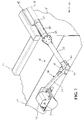
Figure 3 is a fragmentary perspective view of the roller tarp system and motor assembly enclosed within the roller of the roller tarp system; -
Figure 4 is another fragmentary perspective view of the roller tarp system; -
Figure 5 is a fragmentary perspective view of the motor assembly enclosed within the roller of the roller tarp system; -
Figure 6 is another fragmentary perspective view of the motor assembly enclosed within the roller of the roller tarp system; -
Figure 7 is a partially exploded perspective view of the motor assembly; -
Figure 8 is a partially exploded perspective view of the motor assembly and roller of the roller tarp system; -
Figure 9 is an exploded perspective view of the motor assembly; -
Figure 10 is a perspective view of the gear reduction assembly of the motor assembly; and -
Figure 11 is a plan view of the gear reduction assembly. - Referring to the Figures, wherein like numerals indicate like or corresponding parts throughout the several views,
Figures 1 and2 show aroller tarp system 10 according to the present invention for covering and uncovering the bed ortrailer 12 of a truck 14. The truck 14 includes thetruck bed 12 having front andrear ends 16, 18 extending laterally between opposite first andsecond sidewalls truck bed 12 may be a single axle, tandem axle, single or double trailer bed, open trailer bed or the like which have a bed with an open top which needs to be covered by a tarp system. InFigure 1 , theroller tarp system 10 is shown operatively coupled to the front andrear ends 16, 18 of thetruck bed 12, commonly referred to as a side to side tarp system, for selective operation between an open position (shown in phantom) uncovering thetruck bed 12 and a closed position (shown in solid) covering thetruck bed 12. However, it should be appreciated that theroller tarp system 10 may be operatively coupled to the first andsecond sidewalls - Referring to
Figure 1-4 , theroller tarp system 10 includes abase plate 24 fixedly secured to each of the front end 16 andrear end 18 generally midway between thesidewalls roller tarp system 10 between the open and closed positions. Apivot arm assembly base plate 24 by a fixedpivot post 30. Eachpivot arm assembly lower pivot arm 32 extending between a first end pivotally coupled to thebase plate 24 bypivot post 30 and an opposite second end and an elongatedupper pivot arm 34 extending between a first end pivotally coupled to the second send of thelower pivot arm 32 by a fixedknuckle pivot 36 and an opposite second end. Theroller tarp system 10 further includes a hollow,cylindrical tarp spool 38 extending longitudinally between and rotatably coupled to the second ends of each of theupper pivot arms 34 for rotatably spooling and supporting atarp cover 40. Thetarp cover 40 is generally made of flexible fabric, however, other like materials may be utilized without varying the scope of the invention. - Referring specifically to
Figure 4 , thebase plate 24 includes at least one, but preferably a plurality of, first spiral torsion springs 42 for biasing thelower pivot arm 32 in the counterclockwise direction. Preferably, one end of each spring 42 engages a groove or notch formed in the fixedpivot post 30 and an opposite end engages a locator pin on thelower pivot arm 32. Similarly at least one, but preferably a plurality of, secondspiral torsion springs 44 are coupled between thelower pivot arm 32 andupper pivot arm 34 for biasing theupper pivot arm 34 in the counterclockwise direction. Preferably, one end of eachspring 44 engages a groove or notch formed in theknuckle pivot 36 and an opposite end engages a locator pin on theupper pivot arm 34. Additionally, rotation of theupper pivot arm 34 relative to thelower pivot arm 32 is limited by theupper pivot arm 34 engaging a blockingpin 46 projecting from the distal end of thelower pivot arm 32 spaced from theknuckle pivot 36 as shown inFigures 2-4 . - Referring now to
Figures 3-5 , a first end of thetarp spool 38 is slidably and rotatably coupled to the second distal end of theupper pivot arm 34 of thepivot arm assembly 26 by afirst bearing sleeve 48 to allow for both rotation of thetarp spool 38 and axial sliding of the tarp spool along axis A relative to thepivot arm assembly 26. That is, thebearing sleeve 48 allow for axial sliding movement of thetarp spool 38 during actuation between the open and closed positions to account for tolerance, bending, and/or synchronization of the pivotal movement between thepivot arm assemblies truck bed 12. An opposite second end of thetarp spool 38 is operatively and rotatably coupled to the second distal end of theupper pivot arm 34 of thepivot arm assembly 28 by adrive assembly 50. As shown inFigure 5 , thedrive assembly 50 is housed internally within the hollowcylindrical tarp spool 38 so as to conceal thedrive assembly 50 from the external elements, damage, and reduce the overall width of the tarp system. - Referring to
Figures 5-8 , thedrive assembly 50 comprises a first end fixedly secured to the distal second end of theupper pivot arm 34 and an opposite second end fixedly secured to thetarp spool 38. Asecond bearing sleeve 52 is fixedly secured to thetarp spool 38 and receives thedrive assembly 50 therethrough to allow thetarp spool 38 to rotate around and relative to thedrive assembly 50. - More specifically, the
drive assembly 50 includes anelectric DC motor 54 having a first end fixedly connected to the distal second end of theupper pivot arm 34. Amotor output shaft 56 extends axial from the opposite second end of themotor 54 and is rotatably driven by themotor 54. A gear reduction assembly 58 is fixedly secured to themotor 54 and operatively coupled to themotor output shaft 56 for both reducing the output speed while multiplying the output torque of thedrive assembly 50. Anoutput drive shaft 60 extends axial from the gear reduction assembly 58 opposite themotor 54 and is rotatably driven by themotor 54 and gear reduction assembly 58. Finally, adrive hub 62 is fixedly coupled to the distal end of theoutput drive shaft 60 byfastener 64 for rotation therewith. Thedrive hub 62 is further fixedly secured to thetarp spool 38 by a plurality offasteners 68 to transfer rotational movement of theoutput drive shaft 60 to rotational movement of thetarp spool 38. Referring toFigure 8 , thedrive hub 62 is disc-shaped and includes a center bore 68 for receiving theoutput drive shaft 60 therein. The center bore 68 includes anaxial notch 70 formed therein and theoutput drive shaft 60 similarly includes anaxial notch 72 formed therein. A generallyrectangular shear key 74 is aligned with and seated in each of thenotches output drive shaft 60 to thedrive hub 62 and provide a safety feature of shearing in the event the torque on thedrive hub 62 exceed the capability and torque specifications of theoutput drive shaft 60 andmotor 54. Thedrive hub 62 further includes an outer peripheral surface having anaxial slot 74 formed therein and thetarp spool 38 includes an axial protrusion 76 formed in its tube wall corresponding to theaxial slot 74. The protrusion 76 is matingly received in theaxial slot 74 to rotatably connect thedrive hub 62 to thetarp spool 38 and fixedly secured by the fasteners 66. That is, the keyed connection between the protrusion 76 on thetarp spool 38 and theslot 74 in thedrive hub 62 transfer the rotational movement of thedrive hub 62 to corresponding rotational movement of thetarp spool 38. Further, achannel 78 formed on the backside of the axial protrusion 76 receives a plurality of spaced apart locking keys 80 to fixedly secure one edge of thetarp cover 40 to thetarp spool 38. - Referring now to
Figures 9-11 , the gear reduction assembly 58 is shown and discussed in more detail. The gear reduction assembly 58, or gear reducer, is operatively coupled between themotor output shaft 56 and theoutput drive shaft 60 to selectively reduce the speed while multiplying the torque of theoutput drive shaft 60 relative to themotor output shaft 56 for rotation of thetarp spool 38. The gear reduction assembly 58 includes a series of planetary gear sets, however it should be appreciate that one or more planetary gear sets may be used between themotor output shaft 56 and theoutput drive shaft 60 as desired for the rotation of thetarp spool 38. In the preferred embodiment shown, the gear reduction assembly 58 includes a first sun gear 82 fixedly connected to themotor output shaft 56 by pin 84 for rotation therewith. Abearing 86 andseal 88 are seated between the sun gear 82 andmotor 50. The planetary gear sets of the gear reduction assembly 58 are mounted between abearing end cap 90 andmotor mount 92. Thebearing end cap 90 is fixedly secured to themotor 50 bybolts 94 and themotor mount 92 is fixedly secured to thebearing end cap 90 bybolts 96. Each planetary gear set includes a plurality ofplanetary gears 98 in meshed engagement with acircumferential ring gear 100 axially between opposingbearings 102. The planetary gear set further includes acarrier 104 for supporting asun gear 106 and coupled to each of theplanetary gears 98 by anaxle 108. As the first sun gear 82 is rotated by themotor output shaft 56, the first set ofplanetary gears 98 are engaged to transfer rotation and reduce the speed of rotation through thecarrier 104 to thenext sun gear 106 as an output gear. Thefinal carrier 104 includes theoutput drive shaft 60 extending axially therefrom for connection to thedrive hub 62. A pair ofoutput bearings 110 rotatable support theoutput drive shaft 60 through themotor mount 92 and the planetary gear sets are axially fixed by a shim 112 andclip 114 retained on theoutput drive shaft 60. Further, each of the series of ring gears 100 are aligned axially and staked or pinned to each other to prevent rotation. Thus, rotation of the first sun gear 82 by themotor output shaft 56 is transferred and reduced through each set ofplanetary gears 98 andcarriers 104 to theoutput drive shaft 60. It should be appreciated that the number ofplanetary gears 98 may vary as well as the number of planetary gear sets (planetary gears, ring gear, carrier) as required for the desired speed reduction, torque multiplication of theoutput drive shaft 60. Further, the planetary gear sets may vary based on the strength requirements needed or packaging limitations within thetarp spool 38. - In operation, in the open position shown in
Figure 1 with the tarp system uncovering thetruck bed 12, thetarp cover 40 is wound around thetarp spool 38 and supported by a plurality of support hooks 116 extending from thefirst sidewall 20 of thebed 12. The free end of thetarp cover 40 is fixedly secured to thefirst sidewall 20 of thetruck bed 12. When theelectric motor 54 is not energized, thedrive assembly 50 acts as a brake to hold thetarp system 10 in the open position against the bias of the torsion springs 42, 44. When theelectric motor 54 is energized in a first sense, thedrive hub 62 of thedrive assembly 50 rotates thetarp spool 38 in a first direction unwinding thetarp cover 40 and allowing the torsion springs 42, 44 to pivot thepivot arm assemblies first sidewall 20 toward thesecond sidewall 22. Thecover 40 is pulled off thetarp spool 38 and extended over thetruck bed 12. The torsion springs 42, 44 maintain tension on thetarp cover 40 as it is unspooled and extended over thetruck bed 12. As thetarp spool 38 passes the oppositesecond sidewall 22, thespool 38 is wound up against and tucked below at least onelocking flange 118 projecting laterally from thesidewall 22. Themotor 54 is again not energized such that themotor 54 and the torsion springs 42, 44 maintain the tarp system in the closed position covering thetruck bed 12. - In order to actuate the tarp system from the closed position to the open position, the
motor 54 is again energized in a second sense to rotate thedrive hub 62 and thus thetarp spool 38 in an opposite second direction winding thetarp cover 40 around thetarp spool 38. The winding of thetarp cover 40 around thetarp spool 38 by thedrive assembly 50 further pivots thepivot arm assemblies sidewall 22 to the open position adjacent thesidewall 20 whereby thetarp cover 40 is fully wound about thetarp spool 38 and again supported by thehooks 116 in the open position. - With the
drive assembly 50 encased with the hollowcylindrical tarp spool 38 and thetarp system 10 stowed below the top of thesidewalls tarp system 10 is protected from damage during the loading or dumping of thetruck bed 12 and positioned to prevent interfering with either the loading or dumping of thetruck bed 12. Additionally, thedrive assembly 50 is fully enclosed with thetarp spool 38 to prevent exposure to the outside elements or damage during loading or dumping of thetruck bed 12. - The invention has been described in an illustrative manner, and it is to be understood that the terminology, which has been used, is intended to be in the nature of words of description rather than of limitation. Many modifications and variations of the present invention are possible in light of the above teachings. It is, therefore, to be understood that within the scope of the appended claims, the invention may be practiced other than as specifically described.
Claims (12)
- A tarp system (10) covering a truck bed (12), said tarp system (10) comprising:a first pivot arm assembly (26) pivotally coupled to the truck bed (12);a second pivot arm assembly (28) pivotally coupled to the truck bed (12) and spaced from said first pivot arm assembly (26);a generally hollow tarp spool (38) extending along a longitudinal axis between opposite first and second ends, said tarp spool (38) rotatably coupled between said first and second pivot arm assemblies (26, 28) and rotatably supporting a tarp cover (40); characterized in that it further comprisesa drive assembly (50) housed within said tarp spool (38) adjacent one of said first and second ends, said drive assembly (50) operatively coupled between one of said first and second pivot arm assemblies (26, 28) and said tarp spool (38) for selectively rotating said tarp spool (38) and actuating said tarp system (10) between an open position uncovering the truck bed (12) and a closed position covering the truck bed (12), wherein the drive assembly (50) includes a motor (54).
- The tarp system (10) as set forth in claim 1 wherein the motor (54) selectively actuates in a first sense for rotating said tarp spool (38) in a first direction thereby unwinding said tarp cover (40) from said tarp spool (38) to cover the truck bed (12) in said closed position and actuates in a second sense for rotating said tarp spool (38) in a second direction opposite said first direction thereby winding said tarp cover (40) about said tarp spool (38) to uncover the truck bed (12) in said open position.
- The tarp system (10) as set forth in claim 2 wherein said motor (54) includes a first end fixedly coupled to one of said first and second pivot arm assemblies (26, 28) and an opposite second end defined by a motor output shaft (56) rotatably driven by said motor (54) in said first and second directions.
- The tarp system (10) as set form in claim 3 wherein said drive assembly (50) includes a drive hub (62) operatively coupled between said motor output shaft (56) and said tarp spool (38) for rotating said tarp spool (38) in response to rotation of said motor output shaft (56) in said first and second directions.
- The tarp system (10) as set forth in claim 4 wherein said drive assembly (50) includes a gear reduction assembly (58) operatively coupled between said motor output shaft (56) and said drive hub (62) for reducing the relative rotational speed and multiplying the relative torque between said motor output shaft (56) and said drive hub (62).
- The tarp system (10) as set forth in claim 5 wherein said gear reduction assembly (58) includes at least one planetary gear set coupled between said motor output shaft (56) and said drive hub (62).
- The tarp system (10) as set form in claim 6 wherein at least one of said planetary gear sets includes a sun gear (82) operatively coupled to the motor output shaft (56), a ring gear (100), a plurality of planetary gears (98) coupled between said sun gear (82) and said ring gear (100), and a carrier (104) rotatably coupled to said planetary gears (98) and including an output drive shaft (60).
- The tarp system (10) as set forth in claim 7 wherein said drive hub (62) is fixedly connected to said output drive shaft (60) for transferring rotational movement of said output drive shaft (60) to said tarp spool (38).
- The tarp system (10) as set forth in claim 8 further including a first bearing sleeve (48) for rotatably supporting said tarp spool (38) about said drive assembly (50) adjacent said first pivot arm assembly and a second bearing sleeve (52) for rotatably supporting said tarp spool (38) about said second pivot arm assembly (28).
- The tarp system (10) as set forth in claim 9 further including a base (24) mounting said tarp system (10) to the truck bed (12).
- The tarp system (10) as set forth in claim 10 wherein each of said first and second pivot arm assemblies (26, 28) includes a lower pivot arm (32) having a first end pivotally coupled to said base (24) and an opposite second end and an upper pivot arm (34) having a first end pivotally coupled to said second end of said lower pivot arm (32) and an opposite second end coupled to said tarp spool (38) for pivoting said tarp system (10) between said open and closed positions.
- The tarp system (10) as set forth in claim 11 wherein at least one of said first and second pivot arm assemblies (26, 28) includes at least one first torsion spring (42, 44) coupled between said lower pivot arm (32) and said base (24) for biasing said tarp system (10) to said closed position and at least one second torsion spring (42, 44) coupled between said upper pivot arm (34) and said lower pivot arm (32) for biasing said tarp system (10) to said closed position.
Applications Claiming Priority (2)
| Application Number | Priority Date | Filing Date | Title |
|---|---|---|---|
| US201662315053P | 2016-03-30 | 2016-03-30 | |
| PCT/US2017/025215 WO2017173189A1 (en) | 2016-03-30 | 2017-03-30 | Side to side roller tarp system |
Publications (3)
| Publication Number | Publication Date |
|---|---|
| EP3436298A1 EP3436298A1 (en) | 2019-02-06 |
| EP3436298A4 EP3436298A4 (en) | 2019-12-18 |
| EP3436298B1 true EP3436298B1 (en) | 2021-10-27 |
Family
ID=59966458
Family Applications (1)
| Application Number | Title | Priority Date | Filing Date |
|---|---|---|---|
| EP17776728.2A Active EP3436298B1 (en) | 2016-03-30 | 2017-03-30 | Side to side roller tarp system |
Country Status (5)
| Country | Link |
|---|---|
| US (1) | US10696145B2 (en) |
| EP (1) | EP3436298B1 (en) |
| AU (1) | AU2017241832B2 (en) |
| MX (1) | MX2018012022A (en) |
| WO (1) | WO2017173189A1 (en) |
Families Citing this family (6)
| Publication number | Priority date | Publication date | Assignee | Title |
|---|---|---|---|---|
| DE102012023610B4 (en) * | 2012-12-04 | 2025-12-18 | Günter Bauregger | Rolling mechanism of a side cover of a truck and method for controlling the rolling process |
| US10875390B2 (en) * | 2017-08-17 | 2020-12-29 | Sioux City Tarp, Inc. | Tarp deploying device with quick release arm |
| US10675957B2 (en) * | 2018-03-01 | 2020-06-09 | Fabrication Elcargo Inc. | Tarpaulin retraction and extension device |
| US10457191B1 (en) * | 2018-04-12 | 2019-10-29 | Shur-Co, Llc | Tarp cover system with support bow configuration for reducing stress on tarp material |
| CN111688456A (en) * | 2020-06-09 | 2020-09-22 | 宁波信泰机械有限公司 | Pick-up truck rear carriage cover covering and connecting linkage device |
| US12409713B1 (en) * | 2025-02-05 | 2025-09-09 | Shayde Daniel Schmeichel | Roll tarp system |
Citations (1)
| Publication number | Priority date | Publication date | Assignee | Title |
|---|---|---|---|---|
| WO2015175995A1 (en) * | 2014-05-15 | 2015-11-19 | Dometic Corporation | Rotatable awning with illumination |
Family Cites Families (12)
| Publication number | Priority date | Publication date | Assignee | Title |
|---|---|---|---|---|
| FR2604203B2 (en) * | 1981-04-28 | 1989-06-02 | Franciaflex | LATERAL GUIDE BLIND WITH LARGE EXTENSION SUCH AS A VELUM FOR GREENHOUSES, VERANDAS AND THE LIKE. |
| US5002328A (en) * | 1989-06-06 | 1991-03-26 | Walter Michel | Drive system for flexible cover |
| US5887937A (en) * | 1997-03-06 | 1999-03-30 | Searfoss; Timothy Keith | Pivot mounting for a truck bed cover |
| US5944374A (en) * | 1997-06-03 | 1999-08-31 | Searfoss; Timothy Keith | Hinge for a truck bed cover bow |
| US6206449B1 (en) * | 2000-02-22 | 2001-03-27 | Timothy K. Searfoss | Side-to-side truck cover system |
| US6527331B2 (en) * | 2000-12-29 | 2003-03-04 | Timothy K. Searfoss | Bow system for a truck cover |
| US7726720B2 (en) * | 2003-09-17 | 2010-06-01 | Roll-Rite, Llc | Trailer cover system |
| US7350846B2 (en) * | 2004-08-24 | 2008-04-01 | Smith Patents, L.L.C. | Tarpaulin system for covering an open-topped container |
| US8226150B1 (en) * | 2008-05-09 | 2012-07-24 | Agri-Cover, Inc | Roll-up tarp apparatus |
| TWI438115B (en) | 2011-05-06 | 2014-05-21 | Wen Ching Liu | Circular reciprocating power conversion device |
| US9283832B2 (en) | 2011-09-12 | 2016-03-15 | Shur-Co, Llc | Rolling cover system motor mount |
| US8931823B2 (en) | 2013-03-15 | 2015-01-13 | Sioux City Tarp, Inc. | Tarp roll-up with pivoting radial arms |
-
2017
- 2017-03-30 AU AU2017241832A patent/AU2017241832B2/en active Active
- 2017-03-30 US US16/089,451 patent/US10696145B2/en active Active
- 2017-03-30 MX MX2018012022A patent/MX2018012022A/en unknown
- 2017-03-30 WO PCT/US2017/025215 patent/WO2017173189A1/en not_active Ceased
- 2017-03-30 EP EP17776728.2A patent/EP3436298B1/en active Active
Patent Citations (1)
| Publication number | Priority date | Publication date | Assignee | Title |
|---|---|---|---|---|
| WO2015175995A1 (en) * | 2014-05-15 | 2015-11-19 | Dometic Corporation | Rotatable awning with illumination |
Also Published As
| Publication number | Publication date |
|---|---|
| US20190111770A1 (en) | 2019-04-18 |
| AU2017241832B2 (en) | 2022-09-22 |
| AU2017241832A1 (en) | 2018-10-18 |
| CA3019142A1 (en) | 2017-10-05 |
| EP3436298A1 (en) | 2019-02-06 |
| MX2018012022A (en) | 2019-08-05 |
| US10696145B2 (en) | 2020-06-30 |
| EP3436298A4 (en) | 2019-12-18 |
| WO2017173189A1 (en) | 2017-10-05 |
Similar Documents
| Publication | Publication Date | Title |
|---|---|---|
| AU2017241832B2 (en) | Side to side roller tarp system | |
| US6206449B1 (en) | Side-to-side truck cover system | |
| US5722611A (en) | Belt retractor | |
| AU2007214277B2 (en) | Awning assembly including drop-down shade | |
| CN103228857B (en) | There is the variable speed drive of integrated overcurrent protection structure | |
| US6318025B1 (en) | Vehicle liftgate power operating system | |
| EP3192696B1 (en) | Gearbox for actuating a component of a vehicle seat | |
| US6250579B1 (en) | Belt winder | |
| US11167626B2 (en) | Tarpaulin retraction and extension device | |
| US9150086B1 (en) | Tarpaulin retraction and extension device | |
| US7841642B2 (en) | Retractable tarping system | |
| US8931823B2 (en) | Tarp roll-up with pivoting radial arms | |
| US10518618B2 (en) | Tarp motor assembly | |
| US4705148A (en) | Clutch brake assembly | |
| US7080719B2 (en) | Wrap spring brake | |
| US7243699B2 (en) | Window shade with conical winding shaft | |
| US6427981B1 (en) | Secondary latch for a tire carrier | |
| US7275780B2 (en) | Dual tarp cover system | |
| CA3019142C (en) | Side to side roller tarp system | |
| US10131214B2 (en) | Fiberglass roller for tarp deploying device | |
| EP2269846B1 (en) | Device for adjusting camber and/or toe-in / toe-out | |
| CA2853979A1 (en) | Tarpaulin retraction and extension device. | |
| GB2401086A (en) | Load cover | |
| CN217320527U (en) | Adaptive-adjustment dumper fender | |
| KR19990035380U (en) | Automatic switch of two folding cover for a loading box of a freight car |
Legal Events
| Date | Code | Title | Description |
|---|---|---|---|
| STAA | Information on the status of an ep patent application or granted ep patent |
Free format text: STATUS: THE INTERNATIONAL PUBLICATION HAS BEEN MADE |
|
| PUAI | Public reference made under article 153(3) epc to a published international application that has entered the european phase |
Free format text: ORIGINAL CODE: 0009012 |
|
| STAA | Information on the status of an ep patent application or granted ep patent |
Free format text: STATUS: REQUEST FOR EXAMINATION WAS MADE |
|
| 17P | Request for examination filed |
Effective date: 20181029 |
|
| AK | Designated contracting states |
Kind code of ref document: A1 Designated state(s): AL AT BE BG CH CY CZ DE DK EE ES FI FR GB GR HR HU IE IS IT LI LT LU LV MC MK MT NL NO PL PT RO RS SE SI SK SM TR |
|
| AX | Request for extension of the european patent |
Extension state: BA ME |
|
| DAV | Request for validation of the european patent (deleted) | ||
| DAX | Request for extension of the european patent (deleted) | ||
| A4 | Supplementary search report drawn up and despatched |
Effective date: 20191115 |
|
| RIC1 | Information provided on ipc code assigned before grant |
Ipc: B60J 7/00 20060101ALI20191111BHEP Ipc: B60J 11/00 20060101ALI20191111BHEP Ipc: B60J 7/08 20060101AFI20191111BHEP Ipc: B61D 39/00 20060101ALI20191111BHEP Ipc: F16H 48/11 20120101ALI20191111BHEP Ipc: B60P 7/04 20060101ALI20191111BHEP |
|
| STAA | Information on the status of an ep patent application or granted ep patent |
Free format text: STATUS: EXAMINATION IS IN PROGRESS |
|
| 17Q | First examination report despatched |
Effective date: 20201118 |
|
| GRAP | Despatch of communication of intention to grant a patent |
Free format text: ORIGINAL CODE: EPIDOSNIGR1 |
|
| STAA | Information on the status of an ep patent application or granted ep patent |
Free format text: STATUS: GRANT OF PATENT IS INTENDED |
|
| INTG | Intention to grant announced |
Effective date: 20210601 |
|
| GRAS | Grant fee paid |
Free format text: ORIGINAL CODE: EPIDOSNIGR3 |
|
| GRAA | (expected) grant |
Free format text: ORIGINAL CODE: 0009210 |
|
| STAA | Information on the status of an ep patent application or granted ep patent |
Free format text: STATUS: THE PATENT HAS BEEN GRANTED |
|
| AK | Designated contracting states |
Kind code of ref document: B1 Designated state(s): AL AT BE BG CH CY CZ DE DK EE ES FI FR GB GR HR HU IE IS IT LI LT LU LV MC MK MT NL NO PL PT RO RS SE SI SK SM TR |
|
| REG | Reference to a national code |
Ref country code: GB Ref legal event code: FG4D |
|
| REG | Reference to a national code |
Ref country code: CH Ref legal event code: EP |
|
| REG | Reference to a national code |
Ref country code: AT Ref legal event code: REF Ref document number: 1441478 Country of ref document: AT Kind code of ref document: T Effective date: 20211115 |
|
| REG | Reference to a national code |
Ref country code: DE Ref legal event code: R096 Ref document number: 602017048321 Country of ref document: DE |
|
| REG | Reference to a national code |
Ref country code: IE Ref legal event code: FG4D |
|
| REG | Reference to a national code |
Ref country code: NL Ref legal event code: FP |
|
| REG | Reference to a national code |
Ref country code: LT Ref legal event code: MG9D |
|
| REG | Reference to a national code |
Ref country code: AT Ref legal event code: MK05 Ref document number: 1441478 Country of ref document: AT Kind code of ref document: T Effective date: 20211027 |
|
| PG25 | Lapsed in a contracting state [announced via postgrant information from national office to epo] |
Ref country code: RS Free format text: LAPSE BECAUSE OF FAILURE TO SUBMIT A TRANSLATION OF THE DESCRIPTION OR TO PAY THE FEE WITHIN THE PRESCRIBED TIME-LIMIT Effective date: 20211027 Ref country code: LT Free format text: LAPSE BECAUSE OF FAILURE TO SUBMIT A TRANSLATION OF THE DESCRIPTION OR TO PAY THE FEE WITHIN THE PRESCRIBED TIME-LIMIT Effective date: 20211027 Ref country code: FI Free format text: LAPSE BECAUSE OF FAILURE TO SUBMIT A TRANSLATION OF THE DESCRIPTION OR TO PAY THE FEE WITHIN THE PRESCRIBED TIME-LIMIT Effective date: 20211027 Ref country code: BG Free format text: LAPSE BECAUSE OF FAILURE TO SUBMIT A TRANSLATION OF THE DESCRIPTION OR TO PAY THE FEE WITHIN THE PRESCRIBED TIME-LIMIT Effective date: 20220127 Ref country code: AT Free format text: LAPSE BECAUSE OF FAILURE TO SUBMIT A TRANSLATION OF THE DESCRIPTION OR TO PAY THE FEE WITHIN THE PRESCRIBED TIME-LIMIT Effective date: 20211027 |
|
| PG25 | Lapsed in a contracting state [announced via postgrant information from national office to epo] |
Ref country code: IS Free format text: LAPSE BECAUSE OF FAILURE TO SUBMIT A TRANSLATION OF THE DESCRIPTION OR TO PAY THE FEE WITHIN THE PRESCRIBED TIME-LIMIT Effective date: 20220227 Ref country code: SE Free format text: LAPSE BECAUSE OF FAILURE TO SUBMIT A TRANSLATION OF THE DESCRIPTION OR TO PAY THE FEE WITHIN THE PRESCRIBED TIME-LIMIT Effective date: 20211027 Ref country code: PT Free format text: LAPSE BECAUSE OF FAILURE TO SUBMIT A TRANSLATION OF THE DESCRIPTION OR TO PAY THE FEE WITHIN THE PRESCRIBED TIME-LIMIT Effective date: 20220228 Ref country code: PL Free format text: LAPSE BECAUSE OF FAILURE TO SUBMIT A TRANSLATION OF THE DESCRIPTION OR TO PAY THE FEE WITHIN THE PRESCRIBED TIME-LIMIT Effective date: 20211027 Ref country code: NO Free format text: LAPSE BECAUSE OF FAILURE TO SUBMIT A TRANSLATION OF THE DESCRIPTION OR TO PAY THE FEE WITHIN THE PRESCRIBED TIME-LIMIT Effective date: 20220127 Ref country code: LV Free format text: LAPSE BECAUSE OF FAILURE TO SUBMIT A TRANSLATION OF THE DESCRIPTION OR TO PAY THE FEE WITHIN THE PRESCRIBED TIME-LIMIT Effective date: 20211027 Ref country code: HR Free format text: LAPSE BECAUSE OF FAILURE TO SUBMIT A TRANSLATION OF THE DESCRIPTION OR TO PAY THE FEE WITHIN THE PRESCRIBED TIME-LIMIT Effective date: 20211027 Ref country code: GR Free format text: LAPSE BECAUSE OF FAILURE TO SUBMIT A TRANSLATION OF THE DESCRIPTION OR TO PAY THE FEE WITHIN THE PRESCRIBED TIME-LIMIT Effective date: 20220128 Ref country code: ES Free format text: LAPSE BECAUSE OF FAILURE TO SUBMIT A TRANSLATION OF THE DESCRIPTION OR TO PAY THE FEE WITHIN THE PRESCRIBED TIME-LIMIT Effective date: 20211027 |
|
| REG | Reference to a national code |
Ref country code: DE Ref legal event code: R097 Ref document number: 602017048321 Country of ref document: DE |
|
| PG25 | Lapsed in a contracting state [announced via postgrant information from national office to epo] |
Ref country code: SM Free format text: LAPSE BECAUSE OF FAILURE TO SUBMIT A TRANSLATION OF THE DESCRIPTION OR TO PAY THE FEE WITHIN THE PRESCRIBED TIME-LIMIT Effective date: 20211027 Ref country code: SK Free format text: LAPSE BECAUSE OF FAILURE TO SUBMIT A TRANSLATION OF THE DESCRIPTION OR TO PAY THE FEE WITHIN THE PRESCRIBED TIME-LIMIT Effective date: 20211027 Ref country code: RO Free format text: LAPSE BECAUSE OF FAILURE TO SUBMIT A TRANSLATION OF THE DESCRIPTION OR TO PAY THE FEE WITHIN THE PRESCRIBED TIME-LIMIT Effective date: 20211027 Ref country code: EE Free format text: LAPSE BECAUSE OF FAILURE TO SUBMIT A TRANSLATION OF THE DESCRIPTION OR TO PAY THE FEE WITHIN THE PRESCRIBED TIME-LIMIT Effective date: 20211027 Ref country code: DK Free format text: LAPSE BECAUSE OF FAILURE TO SUBMIT A TRANSLATION OF THE DESCRIPTION OR TO PAY THE FEE WITHIN THE PRESCRIBED TIME-LIMIT Effective date: 20211027 Ref country code: CZ Free format text: LAPSE BECAUSE OF FAILURE TO SUBMIT A TRANSLATION OF THE DESCRIPTION OR TO PAY THE FEE WITHIN THE PRESCRIBED TIME-LIMIT Effective date: 20211027 |
|
| PLBE | No opposition filed within time limit |
Free format text: ORIGINAL CODE: 0009261 |
|
| STAA | Information on the status of an ep patent application or granted ep patent |
Free format text: STATUS: NO OPPOSITION FILED WITHIN TIME LIMIT |
|
| 26N | No opposition filed |
Effective date: 20220728 |
|
| PG25 | Lapsed in a contracting state [announced via postgrant information from national office to epo] |
Ref country code: MC Free format text: LAPSE BECAUSE OF FAILURE TO SUBMIT A TRANSLATION OF THE DESCRIPTION OR TO PAY THE FEE WITHIN THE PRESCRIBED TIME-LIMIT Effective date: 20211027 Ref country code: AL Free format text: LAPSE BECAUSE OF FAILURE TO SUBMIT A TRANSLATION OF THE DESCRIPTION OR TO PAY THE FEE WITHIN THE PRESCRIBED TIME-LIMIT Effective date: 20211027 |
|
| REG | Reference to a national code |
Ref country code: CH Ref legal event code: PL |
|
| PG25 | Lapsed in a contracting state [announced via postgrant information from national office to epo] |
Ref country code: SI Free format text: LAPSE BECAUSE OF FAILURE TO SUBMIT A TRANSLATION OF THE DESCRIPTION OR TO PAY THE FEE WITHIN THE PRESCRIBED TIME-LIMIT Effective date: 20211027 |
|
| PG25 | Lapsed in a contracting state [announced via postgrant information from national office to epo] |
Ref country code: LU Free format text: LAPSE BECAUSE OF NON-PAYMENT OF DUE FEES Effective date: 20220330 Ref country code: LI Free format text: LAPSE BECAUSE OF NON-PAYMENT OF DUE FEES Effective date: 20220331 Ref country code: IE Free format text: LAPSE BECAUSE OF NON-PAYMENT OF DUE FEES Effective date: 20220330 Ref country code: CH Free format text: LAPSE BECAUSE OF NON-PAYMENT OF DUE FEES Effective date: 20220331 |
|
| PG25 | Lapsed in a contracting state [announced via postgrant information from national office to epo] |
Ref country code: IT Free format text: LAPSE BECAUSE OF FAILURE TO SUBMIT A TRANSLATION OF THE DESCRIPTION OR TO PAY THE FEE WITHIN THE PRESCRIBED TIME-LIMIT Effective date: 20211027 |
|
| PG25 | Lapsed in a contracting state [announced via postgrant information from national office to epo] |
Ref country code: HU Free format text: LAPSE BECAUSE OF FAILURE TO SUBMIT A TRANSLATION OF THE DESCRIPTION OR TO PAY THE FEE WITHIN THE PRESCRIBED TIME-LIMIT; INVALID AB INITIO Effective date: 20170330 |
|
| PG25 | Lapsed in a contracting state [announced via postgrant information from national office to epo] |
Ref country code: MK Free format text: LAPSE BECAUSE OF FAILURE TO SUBMIT A TRANSLATION OF THE DESCRIPTION OR TO PAY THE FEE WITHIN THE PRESCRIBED TIME-LIMIT Effective date: 20211027 Ref country code: CY Free format text: LAPSE BECAUSE OF FAILURE TO SUBMIT A TRANSLATION OF THE DESCRIPTION OR TO PAY THE FEE WITHIN THE PRESCRIBED TIME-LIMIT Effective date: 20211027 |
|
| PG25 | Lapsed in a contracting state [announced via postgrant information from national office to epo] |
Ref country code: MT Free format text: LAPSE BECAUSE OF FAILURE TO SUBMIT A TRANSLATION OF THE DESCRIPTION OR TO PAY THE FEE WITHIN THE PRESCRIBED TIME-LIMIT Effective date: 20211027 |
|
| REG | Reference to a national code |
Ref country code: DE Ref legal event code: R082 Ref document number: 602017048321 Country of ref document: DE Representative=s name: WITTE, WELLER & PARTNER PATENTANWAELTE MBB, DE |
|
| PG25 | Lapsed in a contracting state [announced via postgrant information from national office to epo] |
Ref country code: TR Free format text: LAPSE BECAUSE OF FAILURE TO SUBMIT A TRANSLATION OF THE DESCRIPTION OR TO PAY THE FEE WITHIN THE PRESCRIBED TIME-LIMIT Effective date: 20211027 |
|
| PGFP | Annual fee paid to national office [announced via postgrant information from national office to epo] |
Ref country code: GB Payment date: 20260324 Year of fee payment: 10 |
|
| PGFP | Annual fee paid to national office [announced via postgrant information from national office to epo] |
Ref country code: DE Payment date: 20260324 Year of fee payment: 10 |
|
| PGFP | Annual fee paid to national office [announced via postgrant information from national office to epo] |
Ref country code: BE Payment date: 20260319 Year of fee payment: 10 |
|
| PGFP | Annual fee paid to national office [announced via postgrant information from national office to epo] |
Ref country code: NL Payment date: 20260319 Year of fee payment: 10 |
|
| PGFP | Annual fee paid to national office [announced via postgrant information from national office to epo] |
Ref country code: FR Payment date: 20260320 Year of fee payment: 10 |