EP3435705A1 - Communication relay and method for redirecting data packets - Google Patents
Communication relay and method for redirecting data packets Download PDFInfo
- Publication number
- EP3435705A1 EP3435705A1 EP17183238.9A EP17183238A EP3435705A1 EP 3435705 A1 EP3435705 A1 EP 3435705A1 EP 17183238 A EP17183238 A EP 17183238A EP 3435705 A1 EP3435705 A1 EP 3435705A1
- Authority
- EP
- European Patent Office
- Prior art keywords
- network component
- data
- data packet
- component
- packets
- Prior art date
- Legal status (The legal status is an assumption and is not a legal conclusion. Google has not performed a legal analysis and makes no representation as to the accuracy of the status listed.)
- Granted
Links
Images




Classifications
-
- H—ELECTRICITY
- H04—ELECTRIC COMMUNICATION TECHNIQUE
- H04W—WIRELESS COMMUNICATION NETWORKS
- H04W36/00—Hand-off or reselection arrangements
- H04W36/02—Buffering or recovering information during reselection ; Modification of the traffic flow during hand-off
- H04W36/023—Buffering or recovering information during reselection
Definitions
- the present disclosure relates to communication relays and methods for redirecting data packets.
- a source base station may still be provided with downlink data even if the mobile communication terminal is no longer to be served by the source base station. Therefore, the source base station typically needs to forward the downlink data to the target base station.
- the source base station needs to forward the downlink data via a relay, e.g. of a core network of the mobile communication network. Accordingly, efficient approaches for relaying (or redirecting) of downlink data are desirable.
- a communication relay comprising a transmitter for transmitting data packets, which comprises user data to be transmitted to a mobile communication terminal, to a first network component of a mobile communication network, a receiver configured to receive a data packet from the first network component, wherein the data packet comprises user data to be transmitted to the mobile communication terminal and an indication that the user data of the data packet is to be forwarded to a second network component and a controller configured to, in response to the reception of the data packet from the first network component, stop the transmitter from transmitting data packets, which comprise user data to be transmitted to the mobile communication terminal, to the first network component and to control the transmitter to forward the user data of the data packet received from the first network component to the second network component and to control the transmitter to start transmitting data packets, which comprise user data to be transmitted to the mobile communication terminal, to the second network component.
- a method for redirecting data packets according to the communication relay described above is provided.
- an S1-based handover is needed whenever an X2-based handover cannot be used. This may be because of lack of connectivity between the source base station and the target base station (i.e. an X2 interface is not deployed between the source base station and the target base station) or a corresponding core network element (MME (mobility management entity)) needs to be relocated.
- MME mobility management entity
- an S1-based handover is an N2-based handover.
- Figure 1 shows a radio communication system 100 according to a 5G architecture.
- the radio communication system 100 includes a radio communication terminal device 102 such as a UE (user equipment), a nano equipment (NE), and the like.
- a radio communication terminal device 102 such as a UE (user equipment), a nano equipment (NE), and the like.
- the radio communication system 100 includes a radio access network 103, which may include a plurality of radio access network nodes, i.e. base stations configured to provide radio access in accordance with a 5G (Fifth Generation) radio access technology (5G New Radio). It should be noted that the radio communication system 100 may also be configured in accordance with LTE (Long Term Evolution) or another mobile radio communication standard but 5G is herein used as an example. Each radio access network node may provide a radio communication with the radio communication terminal device 102 over an air interface 104. It should be noted that the radio access network 103 may include any number of radio access network nodes.
- the radio communication system 100 may further include a core network 109 including a UPF (user plane function) 105, connected to the RAN 103, an Access and Mobility Management Function (AMF) 106 connected to the RAN 103, a Session Management Function (SMF) 107 and a Unified Data Management (UDM) 108.
- UPF user plane function
- AMF Access and Mobility Management Function
- SMF Session Management Function
- UDM Unified Data Management
- the N2 based handover involves signalling between AMF 106 and the SMF 107 in the 5G core network (5GC) 109. If multiple PDU sessions are involved, the AMF 106 needs to send a PDU handover request to each SMF 107 and wait for a response until it proceeds with the handover execution. This causes delay in the handover preparation phase, and may cause handover failure, as radio coverage may be lost during the waiting period.
- 5GC 5G core network
- the source RAN component e.g. source base station
- the target RAN component e.g. target base station
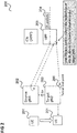
- Figure 2 illustrates a redirection of downlink packets for a handover in a 5G communication system according to an embodiment.
- a mobile terminal 201 moves from the coverage area of a source base station 202 to the coverage area of a target base station 203.
- the base stations 202, 203 are for example part of RAN 103. It is assumed that there is no Xn interface present between the base stations 202, 203.
- downlink (DL) data packets 204 i.e. packets of data to be transmitted to the mobile terminal 201, arriving at a UPF 205 and transmitted to the source base station 202 are redirected by the source base station 202 to the target base station 203 via the UPF 205.
- the user plane is used to control the redirection of the DL data from the source base station 202 to the tunnel end point 206 in the target base station 203.
- the source base station 202 receives an indication of the tunnel end point 206 from the target base station 203, e.g. in the handover response received via the core network (AMF) from the target base station 203.
- AMF core network
- the SMF 107 does not need to be involved in the handover preparation phase to establish the forwarding tunnels between the source base station 202, the target base station 203 and the UPF 205.
- the SMF 107 is updated with the new tunnel information of the target base station 203.
- the SMF 107 can remove or relocate the UPF 105 if needed.
- the GPRS (General Packet Radio Service) Tunnelling Protocol User data (GTP-U) tunnelling protocol may be used.
- the GTP-U protocol is extended to indicate a redirection or redirection endpoint of a PDU (packet data unit). This is illustrated in Figures 3 and 4 .
- FIG. 3 illustrates packet redirection using GTP-U packets.
- a source base station 301 redirects a DL packet by means of a GTP-U packet 302 via a first tunnel 303 to a UPF 304, for example corresponding to UPF 205.
- the GTP-U packet 302 comprises a forwarding indication (i.e. an indication that the GTP-U packet 302 is to be forwarded) and an identifier of a second tunnel 305.
- the UPF 304 redirects packets received via the first tunnel 303 to the second tunnel 305 based on the forwarding indication and the identifier of the second tunnel 305.
- the redirected DL packets arrive at a target base station 306, e.g. corresponding to target base station 203.
- GTP-U packet 302 An example of the GTP-U packet 302 is given in figure 4 .
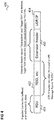
- Figure 4 shows a message 400 according to a GTP-U format for a redirected PDU.
- the message 400 comprises a PDU 401, i.e. an IP (Internet Protocol) packet carrying the downlink data received by the source base station 301 to be redirected to the target base station 306 and for example buffered in the source base station 301.
- PDU 401 i.e. an IP (Internet Protocol) packet carrying the downlink data received by the source base station 301 to be redirected to the target base station 306 and for example buffered in the source base station 301.
- the message 400 further comprises a GTP-U header 402 which identifies the UPF 304 as destination of the message 400.
- the message type is for example "G-PDU”.
- the message 400 comprises a GTP-U extension header 403.
- the GTP-U extension header 403 may indicate that the message 400 is for a redirection of a downlink packet, i.e. carries downlink data to be redirected. It also indicates the target TEID (Tunnelling Endpoint Identifier), i.e. an identifier of the target base station 306 as endpoint of the tunnel.
- target TEID Traffic Endpoint Identifier
- the TEID included in the GTP-U header indicates the tunnel end point in the UPF 304 (in other words the component serving as relay in the redirection) as endpoint of the first tunnel 303
- the TEID in the extension 403 indicates the tunnel endpoint in target base station 306 as endpoint of the second tunnel.
- the TEID in the extension 403 indicates the final destination of the data packets sent by the source base station 301.
- the extension header 403 is for example added to all messages carrying the redirected PDUs from the source base station 301 to the UPF 304.
- the UPF 304 resends the PDU to the TEID identified by the TEID indicated in the extension header 403.
- the message 400 further includes UDP (User Datagram Protocol)/IP header information 404.
- UDP User Datagram Protocol
- IP header information 404 UDP (User Datagram Protocol)/IP header information
- the downlink data packets may be buffered at various stages of the redirection.
- Figure 5 shows an example for a redirection with buffering in the source RAN component and the target RAN component.
- a source RAN component 501 e.g. a source base station
- a target RAN component 502 e.g. a target base station
- a prerequisite for Handover preparation and execution is that the source RAN component 502 sends a handover command 508 to the UE 501.
- the source RAN component 502 then begins to buffer the incoming DL packets 504 in a source RAN component buffer 506.
- the source RAN component 502 uses a redirection operation in the user plane to redirect the buffered packets to the UPF 505.
- the UPF 505 redirects the buffered packets to the target RAN component 503.
- the UPF 505 continues to send incoming DL packets 504 to the source RAN component 502.
- the target RAN component buffers the redirected DL packets it receives from the UPF 505 in a target RAN component buffer 506.
- the UE 501 then notifies the target RAN component 503 that it has handed over by means of a handover notification 509 and the target RAN component 503 begins to send the DL packets it has buffered to the UE 501.
- the target RAN component 503 then sends a Patch Switch request to the core network (not shown) and the CN sends a notification to the UPF 505.
- the UPF 505 then begins to send incoming DL packets 504 directly to the target RAN component 503 (and thus to the UE 501).
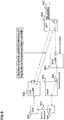
- Figure 6 shows an example for a redirection with buffering in the source RAN component, the target RAN component and the UPF.
- a source RAN component 601 e.g. a source base station
- a target RAN component 602 e.g. a target base station
- a prerequisite for Handover preparation and execution is that the source RAN component 602 sends a handover command 608 to the UE 601.
- the source RAN component 602 then begins to buffer the incoming DL packets 604 in a source RAN component buffer 606.
- the source RAN component 602 uses a redirection operation in the user plane to redirect the buffered packets to the UPF 605.
- the UPF 605 redirects the buffered packets to the target RAN component 603 and begins to buffer incoming DL packets 604 in a UPF buffer 610.
- the target RAN component buffers the redirected DL packets it receives from the UPF 605 in a target RAN component buffer 607.
- the UPF 605 When the UPF 605 has sent the redirected packets it has received from the source RAN component 602, it continues the sending of packets to the target RAN component 603 with the packets from its own buffer 610.
- the UE 601 then notifies the target RAN component 603 that it has handed over by means of a handover notification 609 and the target RAN component 603 begins to send the DL packets it has buffered to the UE 601.
- Figure 7 shows an example for a redirection with buffering in the source RAN component and the UPF.
- a source RAN component 701 e.g. a source base station
- a target RAN component 702 e.g. a target base station
- a prerequisite for Handover preparation and execution is that the source RAN component 702 sends a handover command 708 to the UE 701.
- the source RAN component 702 then begins to buffer the DL packets in a source RAN component buffer 706.
- the source RAN component 702 uses a redirection operation in the user plane to redirect the buffered packets to the UPF 705.
- the UPF 705 begins to buffer the redirected DL packets and incoming DL packets in a UPF buffer 707.
- the UE 701 then notifies the target RAN component 703 that it has handed over by means of a handover notification 709.
- the target RAN component 703 sends a Patch Switch request to the CN (not shown) and the CN sends a notification to the UPF 705.
- the UPF 705 then begins to send the DL packets it has buffered to the target RAN component 703 (and thus to the UE 701).
- the source RAN component 502, 602, 702 buffers DL packets and forwards them to the UPF 505, 605, 705 (as otherwise the buffered packets would be lost).
- the difference in the redirection models is whether the UPF and/or T-RAN have a buffer too.
- a similar HO cancel procedure as in an LTE EPS can be used.
- the source RAN component 502 receives incoming DL packets from the UPF 505 until the UPF sends an end marker and before the reception of the end marker the source RAN component 502 can send a handover cancellation to the target RAN component 503.
- the source RAN component 602 does not receive incoming DL packets after it has redirected its buffered DL packets to the UPF 605.
- a mechanism may be implemented for the source RAN component 602 to notify the UPF 605 to switch back to the source RAN component 602 if the handover needs to be cancelled.
- the mechanism described as described herein can be used to support handovers without interruption of data transmission (e.g. 0ms handover).
- the source RAN component 502 maysend the same DL data via a data radio bearer (DRB) of the source RAN component 502 and to the target RAN component 503 which can send the same data via its own data radio bearer.
- DRB data radio bearer
- such bi-casting to the source RAN component 602, 702 and the target RAN component 603, 703 can be done in the UPF 605, 705.
- a local UPF (I-UPF, Intermediate User Plane Function) may be used to provide access to a local data network.
- the I-UPF has a certain geographical service area. When a UE served by an I-UPF moves out of the I-UPF's service area, the I-UPF may need to be relocated, or removed from the PDU session. When a UE moves into the I-UPF's service area outside from any existing service area, the I-UPF may need to be inserted to the PDU session.
- the I-UPF relocation, insertion or removal may need to be done at the time the UE is paged for DL data and user plane functionalities are being established for the UE. However, it may occur that there is no connectivity from the I-UPF (to be relocated or removed) to the RAN component where the UE receives the paging such that the I-UPF cannot forward downlink packets it may have buffered directly to the RAN component.
- examples are given which allow preventing that the buffered DL packets are lost when the I-UPF is removed or relocated by redirecting the buffered DL packets from the I-UPF.
- Figure 8 shows an example for a redirection of DL packets in case of an I-UPF removal.
- An I-UPF 802 buffers incoming DL packets 807 for an UE 801 which it receives from an UPF 808.
- the UE 801 is paged via a RAN component 803.
- the UE 801 responds to the paging (indicating arrival of DL data for the UE 801) with a service request 804 to an SMF 805.
- the SMF 805 notifies the I-UPF 802 about the service request and an end point 806 of a tunnel from the I-UPF 802 to the RAN component 803.
- the I-UPF 802 uses a redirection operation in the user plane to redirect the buffered DL packets to the UPF 808.
- the UPF 808 sends the redirected packets to the RAN component 803 and begins to buffer incoming DL packets 807.
- the UPF 808 When the UPF 808 has sent the redirected packets received from the I-UPF 802, it continues the transmission of DL packets to the RAN component 803 with the DL packets from its own buffer.
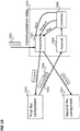
- Figure 9 shows an example for a redirection of DL packets in case of an I-UPF relocation.
- An I-UPF 902 buffers incoming DL packets 907 for an UE 901 which it receives from an UPF 908.
- the UE 901 is paged via a RAN component 903.
- the UE 901 responds to the paging (indicating arrival of DL data for the UE 901) with a service request 904 to an SMF 905.
- the SMF 905 allocates a new I-UPF 909 and notifies the (old) I-UPF 902 about the service request and an end point 906 of a tunnel from the (old) I-UPF 902 to the RAN component 903.
- the (old) I-UPF 902 uses a redirection operation in user plane to redirect the buffered DL packets to the UPF 908.
- the UPF 908 sends the redirected packets to the new I-UPF 909 and begins to buffer incoming DL packets 907.
- the UPF 908 has sent the redirected packets received from the (old) I-UPF 902, it continues the transmission of DL packets to the new I-UPF 909 with the DL packets from its own buffer.
- the approaches of figures 8 and figure 9 for I-UPF relocation and removal may for example be implied in case that the I-UPF acts as an Uplink Classifier (UL CL).
- the UL CL may provide access to a Data Network Access point identified by a DNAI (Data Network Access Identifier).
- DNAI Data Network Access Identifier
- the connectivity to the DNAI can be provided only when the core network can insert in the user plane an UL CL with access to the DNAI.
- the area where the access to the DNAI can be provided is called DNAI service area. If the UE moves in idle mode outside the DNAI service area, the PDU session may involve an existing UL CL which cannot be connected to the RAN (N3) anymore. Since the connectivity to the SMF remains, the UE can be paged but there may not be connectivity between the RAN and the UL CL.
- the SMF removes the UL CL from the PDU session upon reception of Service Request from the UE, if the UE is outside the DNAI service area.
- the DL data is buffered in PSA (PDU Session Anchor), e.g. UPF 808, and the already buffered packets in the UL CL, e.g. I-UPF 802, are redirected back from UL CL, e.g. I-UPF 802, to PSA, e.g. UPF 808.
- PSA PDU Session Anchor
- a communication relay is provided as illustrated in figure 10 .
- Figure 10 shows a communication relay 1000.
- the communication relay 1000 comprises a transmitter 1001 for transmitting data packets 1002, which comprise user data to be transmitted to a mobile communication terminal, to a first network component 1003 of a mobile communication network and a receiver 1004 configured to receive a data packet 1005 from the first network component 1003, wherein the data packet 1005 comprises user data to be transmitted to the mobile communication terminal and an indication 1006 that the user data of the data packet 1005 is to be forwarded to a second network component 1007.
- the communication relay 1000 further comprises a controller 1008 configured to, in response to the reception of the data packet from the first network component 1003,
- a communication relay sends user data for a mobile communication terminal to a first network component until the first network component sends back some of the user data.
- the communication relay sends a plurality of data packets to the first network component and the first network component sends back one of the data packets (possibly repacked or reformatted in any way).
- the first network component stops sending user data to the first network component, i.e. stops sending user data to the mobile communication terminal (e.g.
- the user data sent back can be seen as user data redirected by the first network component.
- the user data is downlink data which the communication relay receives from a communication partner of the mobile communication terminal, e.g. a second mobile communication network, a server computer (e.g. in the Internet) etc.
- the user data sent back includes an information (indication) indicating that the user data is to be forwarded to a second network component by the communication relay. This information may or may not include an identification of the second network component.
- figure 10 may for example be used for a handover where it allows handover preparation to be simple and quick, thus ensuring a high success rate of the handover.
- the approach of figure 10 may for example be applied for a handover in a mobile communication network deployment scenario where an Xn interface has not been deployed between the RAN nodes (e.g. base stations) and thus the Xn interface cannot be used for forwarding packets. It may for example be used when there is no need to relocate an AMF and/or an SMF during the Handover. It should be noted that in 5G the relocation of AMF/SMF is not considered to be an issue in virtualized stateless implementation. An AMF/SMF instance can be reallocated every time for each transaction.
- the same AMF ID can be served from multiple data centres with a different set of Transport Network Layer associations to each data centre, and a change of the AMF ID is not needed. Even if the AMF ID needs to be changed during handover, it means only the 5G-GUTI (Globally Unique Temporary ID) needs to be updated to the UE after the handover.
- 5G-GUTI Globally Unique Temporary ID
- the communication relay for example carries out a method as illustrated in figure 11 .
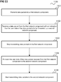
- Figure 11 shows a flow diagram 1100 illustrating a method for redirecting data packets.
- data packets which comprise user data to be transmitted to a mobile communication terminal, are transmitted to a first network component of a mobile communication network.
- a data packet is received from the first network component, wherein the data packet comprises user data to be transmitted to the mobile communication terminal and an indication that the user data of the data packet is to be forwarded to a second network component.
- the components of the communication relay may for example be implemented by one or more circuits.
- a “circuit” may be understood as any kind of a logic implementing entity, which may be special purpose circuitry or a processor executing software stored in a memory, firmware, or any combination thereof.
- a “circuit” may be a hardwired logic circuit or a programmable logic circuit such as a programmable processor, e.g. a microprocessor.
- a “circuit” may also be a processor executing software, e.g. any kind of computer program. Any other kind of implementation of the respective functions which will be described in more detail below may also be understood as a "circuit".
Landscapes
- Engineering & Computer Science (AREA)
- Computer Networks & Wireless Communication (AREA)
- Signal Processing (AREA)
- Mobile Radio Communication Systems (AREA)
Abstract
Description
- The present disclosure relates to communication relays and methods for redirecting data packets.
- In case of a handover of a mobile communication terminal, a source base station may still be provided with downlink data even if the mobile communication terminal is no longer to be served by the source base station. Therefore, the source base station typically needs to forward the downlink data to the target base station. However, there may be scenarios where there is no direct interface between source base station and the target base station and therefore the source base station needs to forward the downlink data via a relay, e.g. of a core network of the mobile communication network. Accordingly, efficient approaches for relaying (or redirecting) of downlink data are desirable.
- According to one embodiment, a communication relay is provided comprising a transmitter for transmitting data packets, which comprises user data to be transmitted to a mobile communication terminal, to a first network component of a mobile communication network, a receiver configured to receive a data packet from the first network component, wherein the data packet comprises user data to be transmitted to the mobile communication terminal and an indication that the user data of the data packet is to be forwarded to a second network component and a controller configured to, in response to the reception of the data packet from the first network component, stop the transmitter from transmitting data packets, which comprise user data to be transmitted to the mobile communication terminal, to the first network component and to control the transmitter to forward the user data of the data packet received from the first network component to the second network component and to control the transmitter to start transmitting data packets, which comprise user data to be transmitted to the mobile communication terminal, to the second network component.
- According to a further embodiment, a method for redirecting data packets according to the communication relay described above is provided.
- In the drawings, like reference characters generally refer to the same parts throughout the different views. The drawings are not necessarily to scale, emphasis instead generally being placed upon illustrating the principles of the invention. In the following description, various aspects are described with reference to the following drawings, in which:
- Figure 1
- shows a radio communication system according to a 5G architecture.
- Figure 2
- illustrates a redirection of downlink packets for a handover in a 5G communication system according to an embodiment.
- Figure 3
- illustrates packet redirection using GTP-U packets.
- Figure 4
- shows a message according to a GTP-U format for a redirected PDU.
- Figure 5
- shows an example for a redirection with buffering in the source RAN component and the target RAN component.
- Figure 6
- shows an example for a redirection with buffering in the source RAN component, the target RAN component and the UPF.
- Figure 7
- shows an example for a redirection with buffering in the source RAN component and the UPF.
- Figure 8
- shows an example for a redirection of DL packets in case of an I-UPF removal.
- Figure 9
- shows an example for a redirection of DL packets in case of an I-UPF relocation.
- Figure 10
- shows a communication relay.
- Figure 11
- shows a flow diagram illustrating a method for redirecting data packets.
- The following detailed description refers to the accompanying drawings that show, by way of illustration, specific details and aspects of this disclosure in which the invention may be practiced. Other aspects may be utilized and structural, logical, and electrical changes may be made without departing from the scope of the invention. The various aspects of this disclosure are not necessarily mutually exclusive, as some aspects of this disclosure can be combined with one or more other aspects of this disclosure to form new aspects.
- In an LTE (Long Term Evolution) communication system, an S1-based handover is needed whenever an X2-based handover cannot be used. This may be because of lack of connectivity between the source base station and the target base station (i.e. an X2 interface is not deployed between the source base station and the target base station) or a corresponding core network element (MME (mobility management entity)) needs to be relocated.
- In a 5G communication network the equivalent of an S1-based handover is an N2-based handover.
-
Figure 1 shows aradio communication system 100 according to a 5G architecture. - The
radio communication system 100 includes a radiocommunication terminal device 102 such as a UE (user equipment), a nano equipment (NE), and the like. - Furthermore, the
radio communication system 100 includes aradio access network 103, which may include a plurality of radio access network nodes, i.e. base stations configured to provide radio access in accordance with a 5G (Fifth Generation) radio access technology (5G New Radio). It should be noted that theradio communication system 100 may also be configured in accordance with LTE (Long Term Evolution) or another mobile radio communication standard but 5G is herein used as an example. Each radio access network node may provide a radio communication with the radiocommunication terminal device 102 over anair interface 104. It should be noted that theradio access network 103 may include any number of radio access network nodes. - The
radio communication system 100 may further include acore network 109 including a UPF (user plane function) 105, connected to the RAN 103, an Access and Mobility Management Function (AMF) 106 connected to the RAN 103, a Session Management Function (SMF) 107 and a Unified Data Management (UDM) 108. - Due to the separation between Mobility Management functionalities, located in the
AMF 106, and Session Management, located in theSMF 107, the N2 based handover involves signalling betweenAMF 106 and theSMF 107 in the 5G core network (5GC) 109. If multiple PDU sessions are involved, the AMF 106 needs to send a PDU handover request to eachSMF 107 and wait for a response until it proceeds with the handover execution. This causes delay in the handover preparation phase, and may cause handover failure, as radio coverage may be lost during the waiting period. - This issue may be addressed by avoiding obtaining a SM (session management) context from the
SMF 107 during the handover preparation phase. However, when direct data forwarding in theRAN 103 is not possible, an indirect data forwarding tunnel establishment still requires the AMF 106 to contact each involvedSMF 107 during the handover preparation phase which again causes delay. - In the following, approaches are described which allow improving the handover success rate in N2 based handovers in a 5G communication system by simplifying the preparation phase. This includes, according to various embodiments, a redirection operation in the user plane which the source RAN component (e.g. source base station) can use to control the redirection of the user plane from the CN to the target RAN component (e.g. target base station).
-
Figure 2 illustrates a redirection of downlink packets for a handover in a 5G communication system according to an embodiment. - A mobile terminal 201 (e.g. corresponding to UE 102) moves from the coverage area of a
source base station 202 to the coverage area of atarget base station 203. Thebase stations base stations - Therefore, downlink (DL)
data packets 204, i.e. packets of data to be transmitted to themobile terminal 201, arriving at a UPF 205 and transmitted to thesource base station 202 are redirected by thesource base station 202 to thetarget base station 203 via the UPF 205. According to various embodiments, the user plane is used to control the redirection of the DL data from thesource base station 202 to thetunnel end point 206 in thetarget base station 203. Thesource base station 202 receives an indication of thetunnel end point 206 from thetarget base station 203, e.g. in the handover response received via the core network (AMF) from thetarget base station 203. - Thus, the
SMF 107 does not need to be involved in the handover preparation phase to establish the forwarding tunnels between thesource base station 202, thetarget base station 203 and the UPF 205. After the handover execution phase, theSMF 107 is updated with the new tunnel information of thetarget base station 203. At this point theSMF 107 can remove or relocate the UPF 105 if needed. - For the tunnel between the
source base station 202 and thetarget base station 203 and the UPF 205, the GPRS (General Packet Radio Service) Tunnelling Protocol User data (GTP-U) tunnelling protocol may be used. - Furthermore, according to various embodiments, the GTP-U protocol is extended to indicate a redirection or redirection endpoint of a PDU (packet data unit). This is illustrated in
Figures 3 and4 . -
Figure 3 illustrates packet redirection using GTP-U packets. - A
source base station 301, for example corresponding to sourcebase station 202, redirects a DL packet by means of a GTP-U packet 302 via afirst tunnel 303 to aUPF 304, for example corresponding toUPF 205. The GTP-U packet 302 comprises a forwarding indication (i.e. an indication that the GTP-U packet 302 is to be forwarded) and an identifier of asecond tunnel 305. TheUPF 304 redirects packets received via thefirst tunnel 303 to thesecond tunnel 305 based on the forwarding indication and the identifier of thesecond tunnel 305. Via thesecond tunnel 305, the redirected DL packets arrive at atarget base station 306, e.g. corresponding to targetbase station 203. - An example of the GTP-
U packet 302 is given infigure 4 . -
Figure 4 shows amessage 400 according to a GTP-U format for a redirected PDU. - The
message 400 comprises aPDU 401, i.e. an IP (Internet Protocol) packet carrying the downlink data received by thesource base station 301 to be redirected to thetarget base station 306 and for example buffered in thesource base station 301. - The
message 400 further comprises a GTP-U header 402 which identifies theUPF 304 as destination of themessage 400. The message type is for example "G-PDU". - In addition, the
message 400 comprises a GTP-U extension header 403. The GTP-U extension header 403 may indicate that themessage 400 is for a redirection of a downlink packet, i.e. carries downlink data to be redirected. It also indicates the target TEID (Tunnelling Endpoint Identifier), i.e. an identifier of thetarget base station 306 as endpoint of the tunnel. - Thus, while the TEID included in the GTP-U header indicates the tunnel end point in the UPF 304 (in other words the component serving as relay in the redirection) as endpoint of the
first tunnel 303, the TEID in theextension 403 indicates the tunnel endpoint intarget base station 306 as endpoint of the second tunnel. In other words, the TEID in theextension 403 indicates the final destination of the data packets sent by thesource base station 301. - The
extension header 403 is for example added to all messages carrying the redirected PDUs from thesource base station 301 to theUPF 304. TheUPF 304 resends the PDU to the TEID identified by the TEID indicated in theextension header 403. - The
message 400 further includes UDP (User Datagram Protocol)/IP header information 404. - The downlink data packets may be buffered at various stages of the redirection.
-
Figure 5 shows an example for a redirection with buffering in the source RAN component and the target RAN component. - Similarly to the example of
figure 2 , there is a handover of aUE 501 from a source RAN component 501 (e.g. a source base station) to a target RAN component 502 (e.g. a target base station) wherein redirection ofdownlink packets 504 is performed via aUPF 505. - A prerequisite for Handover preparation and execution is that the
source RAN component 502 sends ahandover command 508 to theUE 501. Thesource RAN component 502 then begins to buffer theincoming DL packets 504 in a sourceRAN component buffer 506. - The
source RAN component 502 uses a redirection operation in the user plane to redirect the buffered packets to theUPF 505. TheUPF 505 redirects the buffered packets to thetarget RAN component 503. TheUPF 505 continues to sendincoming DL packets 504 to thesource RAN component 502. The target RAN component buffers the redirected DL packets it receives from theUPF 505 in a targetRAN component buffer 506. - The
UE 501 then notifies thetarget RAN component 503 that it has handed over by means of ahandover notification 509 and thetarget RAN component 503 begins to send the DL packets it has buffered to theUE 501. - The
target RAN component 503 then sends a Patch Switch request to the core network (not shown) and the CN sends a notification to theUPF 505. TheUPF 505 then begins to sendincoming DL packets 504 directly to the target RAN component 503 (and thus to the UE 501). -
Figure 6 shows an example for a redirection with buffering in the source RAN component, the target RAN component and the UPF. - Similarly to the example of
figure 5 , there is a handover of aUE 601 from a source RAN component 601 (e.g. a source base station) to a target RAN component 602 (e.g. a target base station) wherein redirection ofdownlink packets 604 is performed via aUPF 605. - A prerequisite for Handover preparation and execution is that the
source RAN component 602 sends ahandover command 608 to theUE 601. Thesource RAN component 602 then begins to buffer theincoming DL packets 604 in a sourceRAN component buffer 606. - The
source RAN component 602 uses a redirection operation in the user plane to redirect the buffered packets to theUPF 605. TheUPF 605 redirects the buffered packets to thetarget RAN component 603 and begins to bufferincoming DL packets 604 in aUPF buffer 610. The target RAN component buffers the redirected DL packets it receives from theUPF 605 in a targetRAN component buffer 607. - When the
UPF 605 has sent the redirected packets it has received from thesource RAN component 602, it continues the sending of packets to thetarget RAN component 603 with the packets from itsown buffer 610. - The
UE 601 then notifies thetarget RAN component 603 that it has handed over by means of ahandover notification 609 and thetarget RAN component 603 begins to send the DL packets it has buffered to theUE 601. -
Figure 7 shows an example for a redirection with buffering in the source RAN component and the UPF. - Similarly to the example of
figure 5 , there is a handover of aUE 701 from a source RAN component 701 (e.g. a source base station) to a target RAN component 702 (e.g. a target base station) wherein redirection ofdownlink packets 704 is performed via aUPF 705. - A prerequisite for Handover preparation and execution is that the
source RAN component 702 sends ahandover command 708 to theUE 701. Thesource RAN component 702 then begins to buffer the DL packets in a sourceRAN component buffer 706. - The
source RAN component 702 uses a redirection operation in the user plane to redirect the buffered packets to theUPF 705. TheUPF 705 begins to buffer the redirected DL packets and incoming DL packets in aUPF buffer 707. - The
UE 701 then notifies thetarget RAN component 703 that it has handed over by means of ahandover notification 709. Thetarget RAN component 703 sends a Patch Switch request to the CN (not shown) and the CN sends a notification to theUPF 705. TheUPF 705 then begins to send the DL packets it has buffered to the target RAN component 703 (and thus to the UE 701). - In all three examples (redirection models) of
figures 5 ,6 ,7 thesource RAN component UPF - Example of
figure 5 : - The user plane redirection request contains the tunnel end point of the
target RAN component 503. - The
source RAN component 502 sends the buffered packets to theUPF 505 which does not buffer them but sends them to thetarget RAN component 503. - There is no buffer in the UPF for the redirected DL packets and the incoming DL packets.
- Upon reception of the Path Switch notification from the target RAN component, the core network (e.g. SMF 107) indicates to the
UPF 505 to switch the tunnel end point directly to the target RAN component. TheSource RAN component 502 stops receiving packets at this point. - Example of
figure 6 : - The user plane redirection request contains the tunnel end point of the
target RAN component 603. - The
source RAN component 602 sends the buffered packets to theUPF 605, which does not buffer them but sends them to thetarget RAN component 603. TheUPF 605 begins to buffer the incoming DL packets after reception of the first redirected packet from thesource RAN component 602. Thesource RAN component 602 stops receiving incoming DL packets at this point. - Once the
UPF 605 has sent all the redirected packets to thetarget RAN component 603, it begins to send the buffered packets from its own buffer to thetarget RAN component 603. - Example of
figure 7 : - The
UPF 705 begins to buffer the incoming DL packets after reception of the first redirected packet from thesource RAN component 702. Thesource RAN component 702 stops receiving DL packets at this point. - There is no tunnel end point in the UP redirection request.
- Upon reception of the Path Switch notification from the
target RAN component 702, the core network (e.g. SMF 107) indicates to theUPF 705 to start sending buffered packets to thetarget RAN component 703. At first the redirected packets from thesource RAN component 702 are sent, followed by the packets buffered byUPF 705. - For handover cancellation, for the approach of
figure 5 , a similar HO cancel procedure as in an LTE EPS (Evolved Packet System) can be used. Thesource RAN component 502 receives incoming DL packets from theUPF 505 until the UPF sends an end marker and before the reception of the end marker thesource RAN component 502 can send a handover cancellation to thetarget RAN component 503. In the approaches offigures 6 and7 , thesource RAN component 602 does not receive incoming DL packets after it has redirected its buffered DL packets to theUPF 605. A mechanism may be implemented for thesource RAN component 602 to notify theUPF 605 to switch back to thesource RAN component 602 if the handover needs to be cancelled. - The mechanism described as described herein can be used to support handovers without interruption of data transmission (e.g. 0ms handover). In the approach of
figure 5 , as thesource RAN component 502 receives the incoming DL packets until the end marker, thesource RAN component 502 maysend the same DL data via a data radio bearer (DRB) of thesource RAN component 502 and to thetarget RAN component 503 which can send the same data via its own data radio bearer. For the approaches offigures 6 and7 , such bi-casting to thesource RAN component target RAN component UPF - In the following, an example is described in which the approaches described above are applied to a local UPF relocation or removal.
- In a 5G communication system, a local UPF (I-UPF, Intermediate User Plane Function) may be used to provide access to a local data network. The I-UPF has a certain geographical service area. When a UE served by an I-UPF moves out of the I-UPF's service area, the I-UPF may need to be relocated, or removed from the PDU session. When a UE moves into the I-UPF's service area outside from any existing service area, the I-UPF may need to be inserted to the PDU session.
- The I-UPF relocation, insertion or removal may need to be done at the time the UE is paged for DL data and user plane functionalities are being established for the UE. However, it may occur that there is no connectivity from the I-UPF (to be relocated or removed) to the RAN component where the UE receives the paging such that the I-UPF cannot forward downlink packets it may have buffered directly to the RAN component. In the following, examples are given which allow preventing that the buffered DL packets are lost when the I-UPF is removed or relocated by redirecting the buffered DL packets from the I-UPF.
-
Figure 8 shows an example for a redirection of DL packets in case of an I-UPF removal. - An I-
UPF 802 buffersincoming DL packets 807 for anUE 801 which it receives from anUPF 808. TheUE 801 is paged via aRAN component 803. TheUE 801 responds to the paging (indicating arrival of DL data for the UE 801) with aservice request 804 to anSMF 805. TheSMF 805 notifies the I-UPF 802 about the service request and anend point 806 of a tunnel from the I-UPF 802 to theRAN component 803. - The I-
UPF 802 uses a redirection operation in the user plane to redirect the buffered DL packets to theUPF 808. TheUPF 808 sends the redirected packets to theRAN component 803 and begins to bufferincoming DL packets 807. - When the
UPF 808 has sent the redirected packets received from the I-UPF 802, it continues the transmission of DL packets to theRAN component 803 with the DL packets from its own buffer. -
Figure 9 shows an example for a redirection of DL packets in case of an I-UPF relocation. - An I-
UPF 902 buffersincoming DL packets 907 for anUE 901 which it receives from anUPF 908. TheUE 901 is paged via aRAN component 903. TheUE 901 responds to the paging (indicating arrival of DL data for the UE 901) with aservice request 904 to anSMF 905. TheSMF 905 allocates a new I-UPF 909 and notifies the (old) I-UPF 902 about the service request and anend point 906 of a tunnel from the (old) I-UPF 902 to theRAN component 903. - The (old) I-
UPF 902 uses a redirection operation in user plane to redirect the buffered DL packets to theUPF 908. TheUPF 908 sends the redirected packets to the new I-UPF 909 and begins to bufferincoming DL packets 907.
When theUPF 908 has sent the redirected packets received from the (old) I-UPF 902, it continues the transmission of DL packets to the new I-UPF 909 with the DL packets from its own buffer. - The approaches of
figures 8 andfigure 9 for I-UPF relocation and removal may for example be implied in case that the I-UPF acts as an Uplink Classifier (UL CL). The UL CL may provide access to a Data Network Access point identified by a DNAI (Data Network Access Identifier). In this case the connectivity to the DNAI can be provided only when the core network can insert in the user plane an UL CL with access to the DNAI. The area where the access to the DNAI can be provided is called DNAI service area. If the UE moves in idle mode outside the DNAI service area, the PDU session may involve an existing UL CL which cannot be connected to the RAN (N3) anymore. Since the connectivity to the SMF remains, the UE can be paged but there may not be connectivity between the RAN and the UL CL. In this case the UE cannot activate the User Plane (N3) to UL CL. The SMF removes the UL CL from the PDU session upon reception of Service Request from the UE, if the UE is outside the DNAI service area. The DL data is buffered in PSA (PDU Session Anchor),e.g. UPF 808, and the already buffered packets in the UL CL, e.g. I-UPF 802, are redirected back from UL CL, e.g. I-UPF 802, to PSA,e.g. UPF 808. - In summary, according to various embodiments, a communication relay is provided as illustrated in
figure 10 . -
Figure 10 shows acommunication relay 1000. - The
communication relay 1000 comprises atransmitter 1001 for transmittingdata packets 1002, which comprise user data to be transmitted to a mobile communication terminal, to afirst network component 1003 of a mobile communication network and areceiver 1004 configured to receive adata packet 1005 from thefirst network component 1003, wherein thedata packet 1005 comprises user data to be transmitted to the mobile communication terminal and anindication 1006 that the user data of thedata packet 1005 is to be forwarded to asecond network component 1007. - The
communication relay 1000 further comprises acontroller 1008 configured to, in response to the reception of the data packet from thefirst network component 1003, - stop the
transmitter 1001 from transmittingdata packets 1002, which comprise user data to be transmitted to the mobile communication terminal, to thefirst network component 1002; and to - control the
transmitter 1001 to forward the user data of thedata packet 1005 received from thefirst network component 1002 to thesecond network component 1007; and to - control the
transmitter 1001 to start transmittingdata packets 1002, which comprise user data to be transmitted to the mobile communication terminal, to thesecond network component 1007. - According to various embodiments, in other words, a communication relay sends user data for a mobile communication terminal to a first network component until the first network component sends back some of the user data. For example, the communication relay sends a plurality of data packets to the first network component and the first network component sends back one of the data packets (possibly repacked or reformatted in any way). In response to the reception of the user data (or data packet) sent back, the first network component stops sending user data to the first network component, i.e. stops sending user data to the mobile communication terminal (e.g. a user equipment) via the first network component and begins sending user data for the mobile communication terminal to the second network component beginning with the user data sent back, followed by any further user data which it has received after receiving the user data sent back. The user data sent back can be seen as user data redirected by the first network component. The user data is downlink data which the communication relay receives from a communication partner of the mobile communication terminal, e.g. a second mobile communication network, a server computer (e.g. in the Internet) etc. The user data sent back includes an information (indication) indicating that the user data is to be forwarded to a second network component by the communication relay. This information may or may not include an identification of the second network component.
- The approach of
figure 10 may for example be used for a handover where it allows handover preparation to be simple and quick, thus ensuring a high success rate of the handover. - The approach of
figure 10 may for example be applied for a handover in a mobile communication network deployment scenario where an Xn interface has not been deployed between the RAN nodes (e.g. base stations) and thus the Xn interface cannot be used for forwarding packets. It may for example be used when there is no need to relocate an AMF and/or an SMF during the Handover. It should be noted that in 5G the relocation of AMF/SMF is not considered to be an issue in virtualized stateless implementation. An AMF/SMF instance can be reallocated every time for each transaction. If there is a need to change the Data Centre during handover, the same AMF ID can be served from multiple data centres with a different set of Transport Network Layer associations to each data centre, and a change of the AMF ID is not needed. Even if the AMF ID needs to be changed during handover, it means only the 5G-GUTI (Globally Unique Temporary ID) needs to be updated to the UE after the handover. - The communication relay for example carries out a method as illustrated in
figure 11 . -
Figure 11 shows a flow diagram 1100 illustrating a method for redirecting data packets. - In 1101, data packets, which comprise user data to be transmitted to a mobile communication terminal, are transmitted to a first network component of a mobile communication network.
- In 1102 a data packet is received from the first network component, wherein the data packet comprises user data to be transmitted to the mobile communication terminal and an indication that the user data of the data packet is to be forwarded to a second network component.
- In response to the reception of the data packet from the first network component, in 1103, transmitting of data packets, which comprise user data to be transmitted to the mobile communication terminal, to the first network component is stopped and in 1104 the user data of the data packet received from the first network component is forwarded to the second network component and in 1105 transmitting data packets, which comprise user data to be transmitted to the mobile communication terminal, to the second network component, is started.
- Various examples are described below:
- Example 1 is a communication relay as illustrated in
figure 10 . - Example 2 is the communication relay of Example 1, wherein the indication that the user data of the data packet is to be forwarded to a second network component includes an indication of the second network component as forwarding destination of the data packet.
- Example 3 is the communication relay of Example 1 or 2, wherein the indication of the second network component is a tunnel end point identifier.
- Example 4 is the communication relay of any one of Examples 1 to 3, wherein the communication relay is a user plane function.
- Example 5 is the communication relay of any one of Examples 1 to 4, wherein forwarding the user data of the data packet comprises extracting the user data to be transmitted to the first network component from the data packet, to generate a forwarding data packet including the user data and to transmit the forwarding data packet to the second network component.
- Example 6 is the communication relay of any one of Examples 1 to 5, wherein the receiver is configured to receive the data packet from the first network component via a first communication tunnel and the received data packet comprises an identifier an end point of the first tunnel in the communication relay.
- Example 7 is the communication relay of Example 5 or 6, wherein the controller is configured to control the transmitter to forward the user data by means of a second tunnel.
- Example 8 is the communication relay of Example 7, wherein the indication of the second network component is an identification of the endpoint of the second tunnel.
- Example 9 is the communication relay of any one of Examples 1 to 8, wherein the receiver is configured to receive the data packet from the first network component via the GTP-U protocol.
- Example 10 is the communication relay of any one of Examples 1 to 9, wherein the first network component is a first radio access network component and the second network component is a second radio access network component and the second radio access network component is the target of a handover of the mobile communication terminal.
- Example 11 is the communication relay of any one of Examples 1 to 9, wherein the first network component is a first user plane function to be removed and the second network component is a radio access network component or a second user plane function.
- Example 12 is the communication relay of any one of Examples 1 to 11, wherein the controller is configured to perform the controlling of the transmitter based on control instructions received from a control plane component of the mobile communication network.
- Example 13 is the communication relay of any one of Examples 1 to 12, wherein the controller is configured to, after stopping the transmitter from transmitting data packets to the first network component, control a memory of the communication relay to start buffering data packets to be transmitted to the mobile communication terminal received by the communication relay.
- Example 14 is the communication relay of Example 13, wherein the controller is configured to control the transmitter to start transmitting the buffered data packets to the second network component in response to a corresponding command from a control plane component including the address of the second network component based on the address of the second network component.
- Example 15 is a method for redirecting data packets as illustrated in
figure 11 . - Example 16 is the method of Example 15, wherein the indication that the user data of the data packet is to be forwarded to a second network component includes an indication of the second network component as forwarding destination of the data packet.
- Example 17 is the method of Example 15 or 16, wherein the indication of the second network component is a tunnel end point identifier.
- Example 18 is the method of any one of Examples 15 to 17, performed by a user plane function.
- Example 19 is the method of any one of Examples 15 to 18, wherein forwarding the user data of the data packet comprises extracting the user data to be transmitted to the first network component from the data packet, to generate a forwarding data packet including the user data and to transmit the forwarding data packet to the second network component.
- Example 20 is the method of any one of Examples 15 to 19, comprising receiving the data packet from the first network component via a first communication tunnel at a communication relay and the received data packet comprising an indication of the communication relay as tunnel end point identifier of the first tunnel in the communication relay.
- Example 21 is the method of Example 19 or 20, comprising forwarding the user data by means of a second tunnel.
- Example 22 is the method of Example 21, wherein the indication of the second network component is an identification of the endpoint of the second tunnel. Example 23 is the method of any one of Examples 1 to 22, comprising receiving the data packet from the first network component via the GTP-U protocol.
- Example 24 is the method of any one of Examples 1 to 23, wherein the first network component is a first radio access network component and the second network component is a second radio access network component and the second radio access network component is the target of a handover of the mobile communication terminal.
- Example 25 is the method of any one of Examples 1 to 23, wherein the first network component is a first user plane function to be removed and the second network component is a radio access network component or a second user plane function.
- Example 26 is the method of any one of Examples 1 to 25, comprising receiving control instructions from a control plane component of the mobile communication network and performing the stopping, forwarding and starting based on the control instructions.
- Example 27 is the method of any one of Examples 1 to 26, comprising, after stopping transmitting data packets to the first network component, starting buffering data packets to be transmitted to the mobile communication terminal received.
- Example 28 is the method of Example 27, comprising starting transmitting the buffered data packets to the second network component in response to a corresponding command from a control plane component including the address of the second network component based on the address of the second network component.
- The components of the communication relay (e.g. the receiver, the controller and the transmitter) may for example be implemented by one or more circuits. A "circuit" may be understood as any kind of a logic implementing entity, which may be special purpose circuitry or a processor executing software stored in a memory, firmware, or any combination thereof. Thus a "circuit" may be a hardwired logic circuit or a programmable logic circuit such as a programmable processor, e.g. a microprocessor. A "circuit" may also be a processor executing software, e.g. any kind of computer program. Any other kind of implementation of the respective functions which will be described in more detail below may also be understood as a "circuit".
- While specific aspects have been described, it should be understood by those skilled in the art that various changes in form and detail may be made therein without departing from the spirit and scope of the aspects of this disclosure as defined by the appended claims. The scope is thus indicated by the appended claims and all changes which come within the meaning and range of equivalency of the claims are therefore intended to be embraced.
Claims (15)
- A communication relay comprising:a transmitter for transmitting data packets, which comprise user data to be transmitted to a mobile communication terminal, to a first network component of a mobile communication network;a receiver configured to receive a data packet from the first network component, wherein the data packet comprises user data to be transmitted to the mobile communication terminal and an indication that the user data of the data packet is to be forwarded to a second network component; anda controller configured to, in response to the reception of the data packet from the first network component,stop the transmitter from transmitting data packets, which comprise user data to be transmitted to the mobile communication terminal, to the first network component; and to control the transmitter to forward the user data of the data packet received from the first network component to the second network component;and to control the transmitter to start transmitting data packets, which comprise user data to be transmitted to the mobile communication terminal, to the second network component.
- The communication relay of claim 1, wherein the indication that the user data of the data packet is to be forwarded to a second network component includes an indication of the second network component as forwarding destination of the data packet.
- The communication relay of claim 1 or 2, wherein the indication of the second network component is a tunnel end point identifier.
- The communication relay of any one of claims 1 to 3, wherein the communication relay is a user plane function.
- The communication relay of any one of claims 1 to 4, wherein forwarding the user data of the data packet comprises extracting the user data to be transmitted to the first network component from the data packet, to generate a forwarding data packet including the user data and to transmit the forwarding data packet to the second network component.
- The communication relay of any one of claims 1 to 5, wherein the receiver is configured to receive the data packet from the first network component via a first communication tunnel and the received data packet comprises an identifier of an end point of the first tunnel in the communication relay.
- The communication relay of claim 5 or 6, wherein the controller is configured to control the transmitter to forward the user data by means of a second tunnel.
- The communication relay of claim 7, wherein the indication of the second network component is an identification of the endpoint of the second tunnel.
- The communication relay of any one of claims 1 to 8, wherein the receiver is configured to receive the data packet from the first network component via the GTP-U protocol.
- The communication relay of any one of claims 1 to 9, wherein the first network component is a first radio access network component and the second network component is a second radio access network component and the second radio access network component is the target of a handover of the mobile communication terminal.
- The communication relay of any one of claims 1 to 9, wherein the first network component is a first user plane function to be removed and the second network component is a radio access network component or a second user plane function.
- The communication relay of any one of claims 1 to 11, wherein the controller is configured to perform the controlling of the transmitter based on control instructions received from a control plane component of the mobile communication network.
- The communication relay of any one of claims 1 to 12, wherein the controller is configured to, after stopping the transmitter from transmitting data packets to the first network component, control a memory of the communication relay to start buffering data packets to be transmitted to the mobile communication terminal received by the communication relay.
- The communication relay of claim 13, wherein the controller is configured to control the transmitter to start transmitting the buffered data packets to the second network component in response to a corresponding command from a control plane component including the address of the second network component based on the address of the second network component.
- A method for redirecting data packets comprising transmitting data packets, which comprise user data to be transmitted to a mobile communication terminal, to a first network component of a mobile communication network;
receiving a data packet from the first network component, wherein the data packet comprises user data to be transmitted to the mobile communication terminal and an indication that the user data of the data packet is to be forwarded to a second network component;
in response to the reception of the data packet from the first network component,stopping transmitting data packets, which comprise user data to be transmitted to the mobile communication terminal, to the first network component; andforwarding the user data of the data packet received from the first network component to the second network component; andstart transmitting data packets, which comprise user data to be transmitted to the mobile communication terminal, to the second network component.
Priority Applications (3)
| Application Number | Priority Date | Filing Date | Title |
|---|---|---|---|
| EP17183238.9A EP3435705B1 (en) | 2017-07-26 | 2017-07-26 | Communication relay and method for redirecting data packets |
| JP2018536274A JP2019525500A (en) | 2017-07-26 | 2018-06-28 | Communication relay and method for redirecting data packets |
| PCT/EP2018/067460 WO2019020309A1 (en) | 2017-07-26 | 2018-06-28 | Communication relay and method for redirecting data packets |
Applications Claiming Priority (1)
| Application Number | Priority Date | Filing Date | Title |
|---|---|---|---|
| EP17183238.9A EP3435705B1 (en) | 2017-07-26 | 2017-07-26 | Communication relay and method for redirecting data packets |
Publications (2)
| Publication Number | Publication Date |
|---|---|
| EP3435705A1 true EP3435705A1 (en) | 2019-01-30 |
| EP3435705B1 EP3435705B1 (en) | 2021-03-31 |
Family
ID=59485186
Family Applications (1)
| Application Number | Title | Priority Date | Filing Date |
|---|---|---|---|
| EP17183238.9A Active EP3435705B1 (en) | 2017-07-26 | 2017-07-26 | Communication relay and method for redirecting data packets |
Country Status (3)
| Country | Link |
|---|---|
| EP (1) | EP3435705B1 (en) |
| JP (1) | JP2019525500A (en) |
| WO (1) | WO2019020309A1 (en) |
Cited By (1)
| Publication number | Priority date | Publication date | Assignee | Title |
|---|---|---|---|---|
| CN111897539A (en) * | 2020-07-20 | 2020-11-06 | 国云科技股份有限公司 | Method and device for deploying applications according to service roles |
Families Citing this family (2)
| Publication number | Priority date | Publication date | Assignee | Title |
|---|---|---|---|---|
| CN118555607A (en) * | 2021-01-04 | 2024-08-27 | 腾讯科技(深圳)有限公司 | Data transmission method, data transmission device, computer readable medium and electronic equipment |
| TWI789255B (en) | 2022-02-25 | 2023-01-01 | 財團法人工業技術研究院 | Multi-access edge computing (mec) system, mec device, user equipment and user plane function (upf) switch method |
Citations (2)
| Publication number | Priority date | Publication date | Assignee | Title |
|---|---|---|---|---|
| EP2375815A1 (en) * | 2010-03-30 | 2011-10-12 | Mitsubishi Electric R&D Centre Europe B.V. | Handover in a home network where data is buffered in a routing module |
| US8406764B1 (en) * | 2006-08-25 | 2013-03-26 | Apple Inc. | Bicasting traffic data during a handover |
Family Cites Families (3)
| Publication number | Priority date | Publication date | Assignee | Title |
|---|---|---|---|---|
| JP2010068107A (en) * | 2008-09-09 | 2010-03-25 | Toshiba Corp | Communication device, communication method, and communication program |
| US8902805B2 (en) * | 2008-10-24 | 2014-12-02 | Qualcomm Incorporated | Cell relay packet routing |
| GB2512659A (en) * | 2013-04-05 | 2014-10-08 | Nec Corp | Communication system |
-
2017
- 2017-07-26 EP EP17183238.9A patent/EP3435705B1/en active Active
-
2018
- 2018-06-28 WO PCT/EP2018/067460 patent/WO2019020309A1/en not_active Ceased
- 2018-06-28 JP JP2018536274A patent/JP2019525500A/en active Pending
Patent Citations (2)
| Publication number | Priority date | Publication date | Assignee | Title |
|---|---|---|---|---|
| US8406764B1 (en) * | 2006-08-25 | 2013-03-26 | Apple Inc. | Bicasting traffic data during a handover |
| EP2375815A1 (en) * | 2010-03-30 | 2011-10-12 | Mitsubishi Electric R&D Centre Europe B.V. | Handover in a home network where data is buffered in a routing module |
Non-Patent Citations (3)
| Title |
|---|
| "3rd Generation Partnership Project; Technical Specification Group Services and System Aspects; Procedures for the 5G System; Stage 2 (Release 15)", no. ;20170701, 14 July 2017 (2017-07-14), XP051309199, Retrieved from the Internet <URL:http://www.3gpp.org/ftp/tsg_sa/WG2_Arch/Latest_SA2_Specs/Latest_draft_S2_Specs/> [retrieved on 20170714] * |
| HUAWEI ET AL: "TS 23.502: Handling PDU sessions rejected by RAN during handover", vol. SA WG2, no. Hangzhou; 20170515 - 20170519, 9 May 2017 (2017-05-09), XP051268605, Retrieved from the Internet <URL:http://www.3gpp.org/ftp/tsg_sa/WG2_Arch/TSGS2_121_Hangzhou/Docs/> [retrieved on 20170509] * |
| SAMSUNG: "TS 23.502: Updates to Inter NG-RAN Node HO Procedure (Section 4.9.1.2.2)", vol. SA WG2, no. Hangzhou, China; 20170515 - 20170519, 9 May 2017 (2017-05-09), XP051268798, Retrieved from the Internet <URL:http://www.3gpp.org/ftp/tsg_sa/WG2_Arch/TSGS2_121_Hangzhou/Docs/> [retrieved on 20170509] * |
Cited By (2)
| Publication number | Priority date | Publication date | Assignee | Title |
|---|---|---|---|---|
| CN111897539A (en) * | 2020-07-20 | 2020-11-06 | 国云科技股份有限公司 | Method and device for deploying applications according to service roles |
| CN111897539B (en) * | 2020-07-20 | 2024-03-29 | 国云科技股份有限公司 | Method and device for deploying application according to service roles |
Also Published As
| Publication number | Publication date |
|---|---|
| JP2019525500A (en) | 2019-09-05 |
| WO2019020309A1 (en) | 2019-01-31 |
| EP3435705B1 (en) | 2021-03-31 |
Similar Documents
| Publication | Publication Date | Title |
|---|---|---|
| US12207325B2 (en) | Method and apparatus for operating wireless communication system having separated mobility management and session management | |
| US10750409B2 (en) | Method and apparatus for non-access stratum message processing during handover in evolved network | |
| US8885600B2 (en) | Enhanced delay management | |
| JP4965738B2 (en) | Data transmission during handover in self-backhaul cell | |
| US20190166634A1 (en) | Communication control method, and related network element | |
| US10368229B2 (en) | Communication apparatus and communication control method in a communication system | |
| CN106465435A (en) | dual connection re-establishment | |
| CN110149166B (en) | Transmission control method, device and system | |
| CN107710862A (en) | The minimum of service disruption is supported using the relaying based on the user equipment of device-to-device to network | |
| KR20160065697A (en) | Method and apparatus for establishing split tcp connention in a communication, and handover method and apparatus | |
| US9961045B2 (en) | Service path changing method and apparatus | |
| CN105075330A (en) | Pdn gateway device and mobile communication method | |
| WO2013071891A1 (en) | Method and device for transmitting uplink data | |
| EP3435705B1 (en) | Communication relay and method for redirecting data packets | |
| CN111200851A (en) | Data communication method and device | |
| CN113661734B (en) | Method and apparatus for optimizing inter-system switching | |
| CN102149147A (en) | Update method of radio bearer and relay station | |
| US11159997B2 (en) | Communication method and apparatus | |
| CN101610462B (en) | Data message sending method, device and communication system | |
| CN105379222B (en) | State synchronization method and equipment based on TCP agent | |
| WO2024094479A1 (en) | Method, apparatus and computer program | |
| CN107872543A (en) | A kind of business transmitting method and device, system |
Legal Events
| Date | Code | Title | Description |
|---|---|---|---|
| STAA | Information on the status of an ep patent application or granted ep patent |
Free format text: STATUS: EXAMINATION IS IN PROGRESS |
|
| PUAI | Public reference made under article 153(3) epc to a published international application that has entered the european phase |
Free format text: ORIGINAL CODE: 0009012 |
|
| 17P | Request for examination filed |
Effective date: 20180125 |
|
| AK | Designated contracting states |
Kind code of ref document: A1 Designated state(s): AL AT BE BG CH CY CZ DE DK EE ES FI FR GB GR HR HU IE IS IT LI LT LU LV MC MK MT NL NO PL PT RO RS SE SI SK SM TR |
|
| AX | Request for extension of the european patent |
Extension state: BA ME |
|
| GRAP | Despatch of communication of intention to grant a patent |
Free format text: ORIGINAL CODE: EPIDOSNIGR1 |
|
| STAA | Information on the status of an ep patent application or granted ep patent |
Free format text: STATUS: GRANT OF PATENT IS INTENDED |
|
| RIC1 | Information provided on ipc code assigned before grant |
Ipc: H04W 36/02 20090101ALN20200514BHEP Ipc: H04W 40/36 20090101AFI20200514BHEP |
|
| RIC1 | Information provided on ipc code assigned before grant |
Ipc: H04W 36/02 20090101ALN20200518BHEP Ipc: H04W 40/36 20090101AFI20200518BHEP |
|
| INTG | Intention to grant announced |
Effective date: 20200617 |
|
| GRAJ | Information related to disapproval of communication of intention to grant by the applicant or resumption of examination proceedings by the epo deleted |
Free format text: ORIGINAL CODE: EPIDOSDIGR1 |
|
| STAA | Information on the status of an ep patent application or granted ep patent |
Free format text: STATUS: EXAMINATION IS IN PROGRESS |
|
| GRAP | Despatch of communication of intention to grant a patent |
Free format text: ORIGINAL CODE: EPIDOSNIGR1 |
|
| INTC | Intention to grant announced (deleted) | ||
| STAA | Information on the status of an ep patent application or granted ep patent |
Free format text: STATUS: GRANT OF PATENT IS INTENDED |
|
| RIC1 | Information provided on ipc code assigned before grant |
Ipc: H04W 40/36 20090101AFI20201001BHEP Ipc: H04W 36/02 20090101ALN20201001BHEP |
|
| INTG | Intention to grant announced |
Effective date: 20201029 |
|
| GRAS | Grant fee paid |
Free format text: ORIGINAL CODE: EPIDOSNIGR3 |
|
| GRAA | (expected) grant |
Free format text: ORIGINAL CODE: 0009210 |
|
| STAA | Information on the status of an ep patent application or granted ep patent |
Free format text: STATUS: THE PATENT HAS BEEN GRANTED |
|
| AK | Designated contracting states |
Kind code of ref document: B1 Designated state(s): AL AT BE BG CH CY CZ DE DK EE ES FI FR GB GR HR HU IE IS IT LI LT LU LV MC MK MT NL NO PL PT RO RS SE SI SK SM TR |
|
| REG | Reference to a national code |
Ref country code: GB Ref legal event code: FG4D Ref country code: CH Ref legal event code: EP |
|
| REG | Reference to a national code |
Ref country code: AT Ref legal event code: REF Ref document number: 1378379 Country of ref document: AT Kind code of ref document: T Effective date: 20210415 |
|
| REG | Reference to a national code |
Ref country code: DE Ref legal event code: R096 Ref document number: 602017035561 Country of ref document: DE |
|
| REG | Reference to a national code |
Ref country code: IE Ref legal event code: FG4D |
|
| REG | Reference to a national code |
Ref country code: LT Ref legal event code: MG9D |
|
| PG25 | Lapsed in a contracting state [announced via postgrant information from national office to epo] |
Ref country code: NO Free format text: LAPSE BECAUSE OF FAILURE TO SUBMIT A TRANSLATION OF THE DESCRIPTION OR TO PAY THE FEE WITHIN THE PRESCRIBED TIME-LIMIT Effective date: 20210630 Ref country code: FI Free format text: LAPSE BECAUSE OF FAILURE TO SUBMIT A TRANSLATION OF THE DESCRIPTION OR TO PAY THE FEE WITHIN THE PRESCRIBED TIME-LIMIT Effective date: 20210331 Ref country code: HR Free format text: LAPSE BECAUSE OF FAILURE TO SUBMIT A TRANSLATION OF THE DESCRIPTION OR TO PAY THE FEE WITHIN THE PRESCRIBED TIME-LIMIT Effective date: 20210331 Ref country code: BG Free format text: LAPSE BECAUSE OF FAILURE TO SUBMIT A TRANSLATION OF THE DESCRIPTION OR TO PAY THE FEE WITHIN THE PRESCRIBED TIME-LIMIT Effective date: 20210630 |
|
| PG25 | Lapsed in a contracting state [announced via postgrant information from national office to epo] |
Ref country code: SE Free format text: LAPSE BECAUSE OF FAILURE TO SUBMIT A TRANSLATION OF THE DESCRIPTION OR TO PAY THE FEE WITHIN THE PRESCRIBED TIME-LIMIT Effective date: 20210331 Ref country code: LV Free format text: LAPSE BECAUSE OF FAILURE TO SUBMIT A TRANSLATION OF THE DESCRIPTION OR TO PAY THE FEE WITHIN THE PRESCRIBED TIME-LIMIT Effective date: 20210331 Ref country code: RS Free format text: LAPSE BECAUSE OF FAILURE TO SUBMIT A TRANSLATION OF THE DESCRIPTION OR TO PAY THE FEE WITHIN THE PRESCRIBED TIME-LIMIT Effective date: 20210331 |
|
| REG | Reference to a national code |
Ref country code: NL Ref legal event code: MP Effective date: 20210331 |
|
| REG | Reference to a national code |
Ref country code: AT Ref legal event code: MK05 Ref document number: 1378379 Country of ref document: AT Kind code of ref document: T Effective date: 20210331 |
|
| PG25 | Lapsed in a contracting state [announced via postgrant information from national office to epo] |
Ref country code: NL Free format text: LAPSE BECAUSE OF FAILURE TO SUBMIT A TRANSLATION OF THE DESCRIPTION OR TO PAY THE FEE WITHIN THE PRESCRIBED TIME-LIMIT Effective date: 20210331 Ref country code: SM Free format text: LAPSE BECAUSE OF FAILURE TO SUBMIT A TRANSLATION OF THE DESCRIPTION OR TO PAY THE FEE WITHIN THE PRESCRIBED TIME-LIMIT Effective date: 20210331 Ref country code: AT Free format text: LAPSE BECAUSE OF FAILURE TO SUBMIT A TRANSLATION OF THE DESCRIPTION OR TO PAY THE FEE WITHIN THE PRESCRIBED TIME-LIMIT Effective date: 20210331 Ref country code: CZ Free format text: LAPSE BECAUSE OF FAILURE TO SUBMIT A TRANSLATION OF THE DESCRIPTION OR TO PAY THE FEE WITHIN THE PRESCRIBED TIME-LIMIT Effective date: 20210331 Ref country code: EE Free format text: LAPSE BECAUSE OF FAILURE TO SUBMIT A TRANSLATION OF THE DESCRIPTION OR TO PAY THE FEE WITHIN THE PRESCRIBED TIME-LIMIT Effective date: 20210331 Ref country code: LT Free format text: LAPSE BECAUSE OF FAILURE TO SUBMIT A TRANSLATION OF THE DESCRIPTION OR TO PAY THE FEE WITHIN THE PRESCRIBED TIME-LIMIT Effective date: 20210331 |
|
| PG25 | Lapsed in a contracting state [announced via postgrant information from national office to epo] |
Ref country code: RO Free format text: LAPSE BECAUSE OF FAILURE TO SUBMIT A TRANSLATION OF THE DESCRIPTION OR TO PAY THE FEE WITHIN THE PRESCRIBED TIME-LIMIT Effective date: 20210331 Ref country code: SK Free format text: LAPSE BECAUSE OF FAILURE TO SUBMIT A TRANSLATION OF THE DESCRIPTION OR TO PAY THE FEE WITHIN THE PRESCRIBED TIME-LIMIT Effective date: 20210331 Ref country code: PL Free format text: LAPSE BECAUSE OF FAILURE TO SUBMIT A TRANSLATION OF THE DESCRIPTION OR TO PAY THE FEE WITHIN THE PRESCRIBED TIME-LIMIT Effective date: 20210331 Ref country code: PT Free format text: LAPSE BECAUSE OF FAILURE TO SUBMIT A TRANSLATION OF THE DESCRIPTION OR TO PAY THE FEE WITHIN THE PRESCRIBED TIME-LIMIT Effective date: 20210802 Ref country code: IS Free format text: LAPSE BECAUSE OF FAILURE TO SUBMIT A TRANSLATION OF THE DESCRIPTION OR TO PAY THE FEE WITHIN THE PRESCRIBED TIME-LIMIT Effective date: 20210731 |
|
| REG | Reference to a national code |
Ref country code: DE Ref legal event code: R097 Ref document number: 602017035561 Country of ref document: DE |
|
| PG25 | Lapsed in a contracting state [announced via postgrant information from national office to epo] |
Ref country code: DK Free format text: LAPSE BECAUSE OF FAILURE TO SUBMIT A TRANSLATION OF THE DESCRIPTION OR TO PAY THE FEE WITHIN THE PRESCRIBED TIME-LIMIT Effective date: 20210331 Ref country code: AL Free format text: LAPSE BECAUSE OF FAILURE TO SUBMIT A TRANSLATION OF THE DESCRIPTION OR TO PAY THE FEE WITHIN THE PRESCRIBED TIME-LIMIT Effective date: 20210331 Ref country code: ES Free format text: LAPSE BECAUSE OF FAILURE TO SUBMIT A TRANSLATION OF THE DESCRIPTION OR TO PAY THE FEE WITHIN THE PRESCRIBED TIME-LIMIT Effective date: 20210331 |
|
| PLBE | No opposition filed within time limit |
Free format text: ORIGINAL CODE: 0009261 |
|
| STAA | Information on the status of an ep patent application or granted ep patent |
Free format text: STATUS: NO OPPOSITION FILED WITHIN TIME LIMIT |
|
| REG | Reference to a national code |
Ref country code: CH Ref legal event code: PL |
|
| 26N | No opposition filed |
Effective date: 20220104 |
|
| GBPC | Gb: european patent ceased through non-payment of renewal fee |
Effective date: 20210726 |
|
| PG25 | Lapsed in a contracting state [announced via postgrant information from national office to epo] |
Ref country code: MC Free format text: LAPSE BECAUSE OF FAILURE TO SUBMIT A TRANSLATION OF THE DESCRIPTION OR TO PAY THE FEE WITHIN THE PRESCRIBED TIME-LIMIT Effective date: 20210331 |
|
| REG | Reference to a national code |
Ref country code: BE Ref legal event code: MM Effective date: 20210731 |
|
| PG25 | Lapsed in a contracting state [announced via postgrant information from national office to epo] |
Ref country code: CH Free format text: LAPSE BECAUSE OF NON-PAYMENT OF DUE FEES Effective date: 20210731 Ref country code: LI Free format text: LAPSE BECAUSE OF NON-PAYMENT OF DUE FEES Effective date: 20210731 Ref country code: GB Free format text: LAPSE BECAUSE OF NON-PAYMENT OF DUE FEES Effective date: 20210726 |
|
| PG25 | Lapsed in a contracting state [announced via postgrant information from national office to epo] |
Ref country code: IS Free format text: LAPSE BECAUSE OF FAILURE TO SUBMIT A TRANSLATION OF THE DESCRIPTION OR TO PAY THE FEE WITHIN THE PRESCRIBED TIME-LIMIT Effective date: 20210731 Ref country code: LU Free format text: LAPSE BECAUSE OF NON-PAYMENT OF DUE FEES Effective date: 20210726 Ref country code: FR Free format text: LAPSE BECAUSE OF NON-PAYMENT OF DUE FEES Effective date: 20210731 |
|
| PG25 | Lapsed in a contracting state [announced via postgrant information from national office to epo] |
Ref country code: IT Free format text: LAPSE BECAUSE OF FAILURE TO SUBMIT A TRANSLATION OF THE DESCRIPTION OR TO PAY THE FEE WITHIN THE PRESCRIBED TIME-LIMIT Effective date: 20210331 Ref country code: IE Free format text: LAPSE BECAUSE OF NON-PAYMENT OF DUE FEES Effective date: 20210726 Ref country code: BE Free format text: LAPSE BECAUSE OF NON-PAYMENT OF DUE FEES Effective date: 20210731 |
|
| P01 | Opt-out of the competence of the unified patent court (upc) registered |
Effective date: 20230330 |
|
| PG25 | Lapsed in a contracting state [announced via postgrant information from national office to epo] |
Ref country code: CY Free format text: LAPSE BECAUSE OF FAILURE TO SUBMIT A TRANSLATION OF THE DESCRIPTION OR TO PAY THE FEE WITHIN THE PRESCRIBED TIME-LIMIT Effective date: 20210331 |
|
| PG25 | Lapsed in a contracting state [announced via postgrant information from national office to epo] |
Ref country code: HU Free format text: LAPSE BECAUSE OF FAILURE TO SUBMIT A TRANSLATION OF THE DESCRIPTION OR TO PAY THE FEE WITHIN THE PRESCRIBED TIME-LIMIT; INVALID AB INITIO Effective date: 20170726 Ref country code: GR Free format text: LAPSE BECAUSE OF FAILURE TO SUBMIT A TRANSLATION OF THE DESCRIPTION OR TO PAY THE FEE WITHIN THE PRESCRIBED TIME-LIMIT Effective date: 20210331 |
|
| PG25 | Lapsed in a contracting state [announced via postgrant information from national office to epo] |
Ref country code: MK Free format text: LAPSE BECAUSE OF FAILURE TO SUBMIT A TRANSLATION OF THE DESCRIPTION OR TO PAY THE FEE WITHIN THE PRESCRIBED TIME-LIMIT Effective date: 20210331 |
|
| PG25 | Lapsed in a contracting state [announced via postgrant information from national office to epo] |
Ref country code: MT Free format text: LAPSE BECAUSE OF FAILURE TO SUBMIT A TRANSLATION OF THE DESCRIPTION OR TO PAY THE FEE WITHIN THE PRESCRIBED TIME-LIMIT Effective date: 20210331 |
|
| PGFP | Annual fee paid to national office [announced via postgrant information from national office to epo] |
Ref country code: DE Payment date: 20250722 Year of fee payment: 9 |
|
| PG25 | Lapsed in a contracting state [announced via postgrant information from national office to epo] |
Ref country code: TR Free format text: LAPSE BECAUSE OF FAILURE TO SUBMIT A TRANSLATION OF THE DESCRIPTION OR TO PAY THE FEE WITHIN THE PRESCRIBED TIME-LIMIT Effective date: 20210331 |