EP3435611A1 - Method and apparatus of data transmission over guard sub-carriers in multi-carrier ofdm systems - Google Patents
Method and apparatus of data transmission over guard sub-carriers in multi-carrier ofdm systems Download PDFInfo
- Publication number
- EP3435611A1 EP3435611A1 EP18187496.7A EP18187496A EP3435611A1 EP 3435611 A1 EP3435611 A1 EP 3435611A1 EP 18187496 A EP18187496 A EP 18187496A EP 3435611 A1 EP3435611 A1 EP 3435611A1
- Authority
- EP
- European Patent Office
- Prior art keywords
- carrier
- carriers
- data transmission
- frequency channels
- sub
- Prior art date
- Legal status (The legal status is an assumption and is not a legal conclusion. Google has not performed a legal analysis and makes no representation as to the accuracy of the status listed.)
- Ceased
Links
Images






Classifications
-
- H—ELECTRICITY
- H04—ELECTRIC COMMUNICATION TECHNIQUE
- H04L—TRANSMISSION OF DIGITAL INFORMATION, e.g. TELEGRAPHIC COMMUNICATION
- H04L27/00—Modulated-carrier systems
- H04L27/26—Systems using multi-frequency codes
- H04L27/2601—Multicarrier modulation systems
- H04L27/2626—Arrangements specific to the transmitter only
-
- H—ELECTRICITY
- H04—ELECTRIC COMMUNICATION TECHNIQUE
- H04J—MULTIPLEX COMMUNICATION
- H04J11/00—Orthogonal multiplex systems, e.g. using WALSH codes
-
- H—ELECTRICITY
- H04—ELECTRIC COMMUNICATION TECHNIQUE
- H04L—TRANSMISSION OF DIGITAL INFORMATION, e.g. TELEGRAPHIC COMMUNICATION
- H04L25/00—Baseband systems
- H04L25/02—Details ; arrangements for supplying electrical power along data transmission lines
- H04L25/03—Shaping networks in transmitter or receiver, e.g. adaptive shaping networks
- H04L25/03006—Arrangements for removing intersymbol interference
- H04L25/03343—Arrangements at the transmitter end
-
- H—ELECTRICITY
- H04—ELECTRIC COMMUNICATION TECHNIQUE
- H04L—TRANSMISSION OF DIGITAL INFORMATION, e.g. TELEGRAPHIC COMMUNICATION
- H04L25/00—Baseband systems
- H04L25/02—Details ; arrangements for supplying electrical power along data transmission lines
- H04L25/03—Shaping networks in transmitter or receiver, e.g. adaptive shaping networks
- H04L25/03006—Arrangements for removing intersymbol interference
- H04L25/03821—Inter-carrier interference cancellation [ICI]
-
- H—ELECTRICITY
- H04—ELECTRIC COMMUNICATION TECHNIQUE
- H04L—TRANSMISSION OF DIGITAL INFORMATION, e.g. TELEGRAPHIC COMMUNICATION
- H04L27/00—Modulated-carrier systems
- H04L27/26—Systems using multi-frequency codes
- H04L27/2601—Multicarrier modulation systems
- H04L27/2626—Arrangements specific to the transmitter only
- H04L27/2646—Arrangements specific to the transmitter only using feedback from receiver for adjusting OFDM transmission parameters, e.g. transmission timing or guard interval length
-
- H—ELECTRICITY
- H04—ELECTRIC COMMUNICATION TECHNIQUE
- H04L—TRANSMISSION OF DIGITAL INFORMATION, e.g. TELEGRAPHIC COMMUNICATION
- H04L27/00—Modulated-carrier systems
- H04L27/26—Systems using multi-frequency codes
- H04L27/2601—Multicarrier modulation systems
- H04L27/2647—Arrangements specific to the receiver only
-
- H—ELECTRICITY
- H04—ELECTRIC COMMUNICATION TECHNIQUE
- H04L—TRANSMISSION OF DIGITAL INFORMATION, e.g. TELEGRAPHIC COMMUNICATION
- H04L5/00—Arrangements affording multiple use of the transmission path
- H04L5/0001—Arrangements for dividing the transmission path
- H04L5/0003—Two-dimensional division
- H04L5/0005—Time-frequency
- H04L5/0007—Time-frequency the frequencies being orthogonal, e.g. OFDM(A) or DMT
-
- H—ELECTRICITY
- H04—ELECTRIC COMMUNICATION TECHNIQUE
- H04L—TRANSMISSION OF DIGITAL INFORMATION, e.g. TELEGRAPHIC COMMUNICATION
- H04L5/00—Arrangements affording multiple use of the transmission path
- H04L5/0001—Arrangements for dividing the transmission path
- H04L5/0003—Two-dimensional division
- H04L5/0005—Time-frequency
- H04L5/0007—Time-frequency the frequencies being orthogonal, e.g. OFDM(A) or DMT
- H04L5/001—Time-frequency the frequencies being orthogonal, e.g. OFDM(A) or DMT the frequencies being arranged in component carriers
-
- H—ELECTRICITY
- H04—ELECTRIC COMMUNICATION TECHNIQUE
- H04L—TRANSMISSION OF DIGITAL INFORMATION, e.g. TELEGRAPHIC COMMUNICATION
- H04L5/00—Arrangements affording multiple use of the transmission path
- H04L5/0001—Arrangements for dividing the transmission path
- H04L5/0014—Three-dimensional division
- H04L5/0023—Time-frequency-space
-
- H—ELECTRICITY
- H04—ELECTRIC COMMUNICATION TECHNIQUE
- H04L—TRANSMISSION OF DIGITAL INFORMATION, e.g. TELEGRAPHIC COMMUNICATION
- H04L5/00—Arrangements affording multiple use of the transmission path
- H04L5/003—Arrangements for allocating sub-channels of the transmission path
- H04L5/0037—Inter-user or inter-terminal allocation
- H04L5/0039—Frequency-contiguous, i.e. with no allocation of frequencies for one user or terminal between the frequencies allocated to another
-
- H—ELECTRICITY
- H04—ELECTRIC COMMUNICATION TECHNIQUE
- H04L—TRANSMISSION OF DIGITAL INFORMATION, e.g. TELEGRAPHIC COMMUNICATION
- H04L5/00—Arrangements affording multiple use of the transmission path
- H04L5/003—Arrangements for allocating sub-channels of the transmission path
- H04L5/0037—Inter-user or inter-terminal allocation
- H04L5/0041—Frequency-non-contiguous
-
- H—ELECTRICITY
- H04—ELECTRIC COMMUNICATION TECHNIQUE
- H04L—TRANSMISSION OF DIGITAL INFORMATION, e.g. TELEGRAPHIC COMMUNICATION
- H04L5/00—Arrangements affording multiple use of the transmission path
- H04L5/003—Arrangements for allocating sub-channels of the transmission path
- H04L5/0044—Allocation of payload; Allocation of data channels, e.g. PDSCH or PUSCH
-
- H—ELECTRICITY
- H04—ELECTRIC COMMUNICATION TECHNIQUE
- H04L—TRANSMISSION OF DIGITAL INFORMATION, e.g. TELEGRAPHIC COMMUNICATION
- H04L5/00—Arrangements affording multiple use of the transmission path
- H04L5/003—Arrangements for allocating sub-channels of the transmission path
- H04L5/0048—Allocation of pilot signals, i.e. of signals known to the receiver
-
- H—ELECTRICITY
- H04—ELECTRIC COMMUNICATION TECHNIQUE
- H04L—TRANSMISSION OF DIGITAL INFORMATION, e.g. TELEGRAPHIC COMMUNICATION
- H04L5/00—Arrangements affording multiple use of the transmission path
- H04L5/003—Arrangements for allocating sub-channels of the transmission path
- H04L5/0053—Allocation of signalling, i.e. of overhead other than pilot signals
-
- H—ELECTRICITY
- H04—ELECTRIC COMMUNICATION TECHNIQUE
- H04W—WIRELESS COMMUNICATION NETWORKS
- H04W72/00—Local resource management
- H04W72/02—Selection of wireless resources by user or terminal
-
- H—ELECTRICITY
- H04—ELECTRIC COMMUNICATION TECHNIQUE
- H04W—WIRELESS COMMUNICATION NETWORKS
- H04W72/00—Local resource management
- H04W72/04—Wireless resource allocation
- H04W72/044—Wireless resource allocation based on the type of the allocated resource
- H04W72/0453—Resources in frequency domain, e.g. a carrier in FDMA
-
- H—ELECTRICITY
- H04—ELECTRIC COMMUNICATION TECHNIQUE
- H04L—TRANSMISSION OF DIGITAL INFORMATION, e.g. TELEGRAPHIC COMMUNICATION
- H04L27/00—Modulated-carrier systems
- H04L27/26—Systems using multi-frequency codes
- H04L27/2601—Multicarrier modulation systems
- H04L27/2647—Arrangements specific to the receiver only
- H04L27/2655—Synchronisation arrangements
- H04L27/2666—Acquisition of further OFDM parameters, e.g. bandwidth, subcarrier spacing, or guard interval length
Definitions
- the disclosed embodiments relate generally to wireless network communications, and, more particularly, to data communication over guard sub-carriers and flexible radio frequency transceiver architecture in multi-carrier OFDM systems.
- radio bandwidths are typically used for up to 100Mbps peak transmission rate.
- Much higher peak transmission rate is required for next generation wireless systems.
- 1Gbps peak transmission rate is required by ITU-R for IMT-Advanced systems such as the 4 th generation (“4G") mobile communications systems.
- the current transmission technologies are very difficult to perform 100bps/Hz transmission spectrum efficiency. In the foreseeable next few years, only up to 15bps/Hz transmission spectrum efficiency can be anticipated. Therefore, much wider radio bandwidths (i.e., at least 40MHz) will be necessary for next generation wireless communications systems to achieve 1Gbps peak transmission rate.
- Orthogonal Frequency Division Multiplexing is an efficient multiplexing scheme to perform high transmission rate over frequency selective channel without the disturbance from inter-carrier interference.
- OFDM Orthogonal Frequency Division Multiplexing
- a single radio frequency (RF) carrier is used to carry one wideband radio signal
- multiple RF carriers are used to carry multiple narrower band radio signals.
- An OFDM multi-carrier system has various advantages as compared to a traditional OFDM system such as easier backward compatibility, better reuse on legacy single-carrier hardware design, more mobile station hardware flexibility, and lower Peak to Average Power Ratio (PAPR) for uplink transmission.
- PAPR Peak to Average Power Ratio
- OFDM multi-carrier systems have become the baseline system architecture in IEEE 802.16m and 3GPP LTE-Advanced draft standards to fulfill system requirements.
- WO 2008/118429 A1 discloses an example of typical multi-carrier OFDM or OFDMA bandwidth allocation with the guard subcarriers.
- JP 2002 290 364 A discloses a concept to avoid wasting spectrum bandwidth on guard subcarriers between two neighboring channels.
- Figure 1 illustrates a typical architecture to utilize much wider radio bandwidth for OFDM multi-carrier system 11.
- multiple RF carriers are used to carry multiple radio signals with narrower bandwidth (called narrower band radio signal).
- the total radio bandwidth of OFDM multi-carrier system 11 is 40 MHz, and four RF carriers #1-#4 are used to carry four narrower band radio signals #1-#4, each transmitted through a corresponding 10MHz frequency channel #1-#4 (i.e., 10MHz Bandwidth, 1024FFT).
- the overall radio bandwidth is further partitioned into a large number of sub-carriers, which are closely spaced and orthogonal to each other for data transmission.
- sub-carriers in between adjacent frequency channels may be overlap with each other. Therefore, overlapping sub-carriers located in between adjacent frequency channels are typically reserved as guard sub-carriers to prevent signal interference.
- a certain number of sub-carriers are reserved as NULL sub-carriers such that they are not used for data transmission.
- both adjacent frequency channels are controlled and managed by the same base station, then it is not necessary to have those overlapping sub-carriers in between adjacent frequency channels to be reserved as guard sub-carriers. Instead, the guard sub-carriers in between adjacent frequency channels may be used for data transmission such that overall system throughput can be increased.
- guard sub-carriers can increase system throughput by 2.08% for two contiguous 10MHz frequency channels, by 2.77% for three contiguous 10MHz frequency channels, and by 3.125% for four contiguous 10MHz frequency channels. It is thus desirable to enable data transmission over guard sub-carriers to increase overall system throughput and peak transmission rate.
- a method of data transmission over guard sub-carriers is provided in a multi-carrier OFDM system.
- Adjacent radio frequency (RF) carriers are used to carry radio signals transmitted through adjacent frequency channels.
- a plurality of guard sub-carriers between adjacent frequency channels are aligned and identified for data transmission in a pre-defined physical resource unit.
- the identified guard sub-carriers do not overlap with normal data sub-carriers of the radio signals transmitted through the adjacent frequency channels.
- At least one of the identified guard sub-carriers is reserved as NULL sub-carrier.
- Overall system throughput is increased by utilizing guard sub-carriers for data transmission.
- a serving base station periodically transmits a reference signal over the guard sub-carriers that are utilized for data transmission.
- the use of the reference signal saves overhead on MAC message indication and provides flexibility for various guard sub-carrier allocation scenarios.
- a Subsidiary Carrier consisting of aggregated guard sub-carriers utilized for data transmission is defined.
- the serving base station may use a simple MAC layer indication to indicate whether guard sub-carriers are supported for data transmission with a particular mobile station.
- a flexible multi-carrier transceiver architecture is provided in a multi-carrier OFDM system.
- Different multi-carrier and/or MIMO/SISO data transmission schemes are implemented by adaptively reconfigure same hardware modules including a common MAC layer module, an adaptive multi-carrier controller, multiple physical layer entities, and multiple RF entities.
- a single-carrier 4x4 MIMO data transmission scheme is supported; in a second embodiment, a multi-carrier (two RF carriers) 2x2 MIMO data transmission scheme is supported; and in a third embodiment, a multi-carrier (four RF carriers) SISO data transmission scheme is supported.
- the number of antennas for MIMO transmission over each frequency channel is the total number of RF entities divided by the number of supported active frequency channels.
- the flexible multi-carrier transceiver architecture can be used to support data transmission over guard sub-carriers.
- a mobile station supports two contiguous 10MHz frequency channels.
- its transceiver hardware is implemented by utilizing two 1024 FFTs and two 10MHz bandwidth RF filters to transmit and receive 2x10MHz OFDMA signals through two adjacent frequency channels.
- its transceiver hardware is implemented by utilizing a single 2048 FFT and one 20MHz bandwidth RF filer to transmit and receive 2x10MHz OFDMA signals through two adjacent frequency channels.
- the overlapped sub-carriers are always aligned and the mobile station can easily transmit/receive radio signals over the guard sub-carriers between the two adjacent frequency channels.
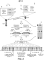
- FIG. 2 illustrates a method of data transmission over guard sub-carriers in a multi-carrier Orthogonal Frequency Division Multiplexing (OFDM) wireless communications system 21 in accordance with a first novel aspect.
- Wireless system 21 comprises a multi-carrier base station BS22 and a multi-carrier mobile station MS23.
- BS22 comprises a multi-carrier radio frequency (RF) module 24 coupled to a plurality of antennas, supporting multiple RF carriers for data transmission.
- MS23 comprises a multi-carrier RF module 25 coupled to a plurality of antennas, supporting multiple RF carriers for data transmission.
- RF radio frequency
- two contiguous radio RF carriers #1 and #2 are used to carry two radio signals #1 and #2, each transmitted through a corresponding 10MHz frequency channel #1-#2 (i.e., 10MHz Bandwidth, 1024FFT) respectively.
- 10MHz frequency channel #1-#2 i.e., 10MHz Bandwidth, 1024FFT
- the overall radio bandwidth is further partitioned into a large number of sub-carriers, which are closely spaced and orthogonal to each other for data transmission over each radio signal.
- data streams are communicated between BS22 and MS23 using a pre-defined physical resource unit (PRU) 26, comprising a number of consecutive sub-carriers in frequency domain and a number of consecutive OFDM symbols in time domain.
- PRU physical resource unit
- RF carriers #1 and #2 When there are contiguous RF carriers (e.g., RF carriers #1 and #2) used for data transmission, sub-carriers located at both end of each frequency channel may be overlap with each other. To prevent signal interference, those sub-carriers are reserved as guard sub-carriers. Typically, guard sub-carriers are configured as NULL sub-carriers and cannot be used for data transmission. In one novel aspect, with more details described below with respect to Figure 3 , a certain number of the originally reserved guard sub-carriers are aligned and then identified to support data transmission using a pre-defined PRU. In the example of Figure 2 , PRU 26 comprises eighteen consecutive sub-carriers and six consecutive OFDM symbols. The same PRU size is used for data transmission over normal data sub-carriers as well as the identified guard sub-carriers. In addition, the same pilot pattern designed for normal data sub-carriers can also be used for the identified guard sub-carriers.
- PRU 26 comprises eighteen consecutive sub-carrier
- Figure 3 illustrates a method of aligning and indentifying guard sub-carriers for data transmission in wireless system 21.
- the overlapped guard sub-carriers between adjacent frequency channels #1 and #2 can be utilized for data transmission only if the sub-carriers of radio signal #1 transmitted through frequency channel #1 are well aligned with the sub-carriers of radio signals transmitted through adjacent frequency channels (e.g., radio signal #2 transmitted through frequency channel #2) in frequency domain.
- Alignment can be achieved by applying a frequency offset over the RF carrier frequency of the radio signals.
- a 3.128KHz frequency offset is applied over the RF carrier frequency of radio signal #2 to make it shifted from the center frequency of frequency channel #2 in order to align the overlapped guard sub-carriers of the radio signal transmitted through two adjacent 10MHz frequency channels.
- sub-carrier alignment see related documents such as IEEE 802.16m-09/0267r1, "Text Input for Sub-Carrier Alignment based on P802.16m SDD", the subject matter of which is incorporated herein by reference.
- each frequency channel comprises 864 (2 * 432) sub-carriers, which is partitioned into 48 (2 * 24) PRUs for data transmission.
- forty-seven guard sub-carriers in between the two adjacent frequency channels #1 and #2 do not overlap with normal data sub-carriers of radio signal #1 and #2.
- Those guard sub-carriers are identified by wireless system 21 as sub-carriers that can be used for data transmission.
- Each combination of different bandwidth for adjacent frequency channels will result in different number of available guard sub-carriers for data transmission. It will thus result in high overhead if wireless system 21 needs to explicitly signaling all the possible numbers of available guard sub-carrier under different combinations.
- the identified guard sub-carriers are partitioned into PRUs for data transmission.
- the same PRU size and pilot pattern designed for normal data sub-carriers can be reused for the identified guard sub-carriers.
- certain physical layer design such as channel estimation algorithm can also be reused.
- hardware complexity and signaling overhead is reduced because signaling can be performed in a predefine PRU size rather than in an arbitrary number.
- Figure 4 illustrates a method of reserving at least one guard sub-carrier as NULL sub-carrier when supporting data transmission.
- method #1 two separate physical layer modules (PHY#1 and PHY#2) are used as the baseband hardware modules to utilize two 1024 FFT and two 10MHz RF filters to transmit/receive 2x10MHz OFDMA radio signals over two adjacent frequency channels.
- the RF carrier frequency of each frequency channel referred to as direct current (DC) sub-carrier, needs to be reserved as NULL sub-carrier to avoid signal interference.
- DC direct current
- one single physical layer module is shared as the baseband hardware module to utilize a 2048 FFT and a 20MHz bandwidth RF filter to transmit/receive 2x10MHz OFDMA radio signals in parallel over two adjacent frequency channels.
- the RF carrier frequency (DC sub-carrier) under method #2 also needs to be reserved as NULL sub-carrier to avoid signal interference.
- the DC sub-carrier belongs to one of the identified guard sub-carriers. Thus, to ensure proper data transmission, at least one indentified guard sub-carrier needs to be reserved as NULL sub-carrier.
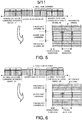
- Figures 5-6 illustrate two examples of transmitting a reference signal over guard sub-carriers.
- the serving base station still need to communicate with the mobile stations on which guard sub-carriers are actually allocated and utilized for data transmission. Using a MAC message to indicate such allocation explicitly may result in high overhead. Instead, the serving base station periodically transmits a reference signal (e.g., preamble) over the guard sub-carriers that are used for data transmission such that the mobile stations may detect the location of the utilized guard sub-carriers.
- a reference signal e.g., preamble
- all identified guard subcarriers are utilized for data transmission.
- only some of the identified guard sub-carriers are utilized for data transmission.
- the serving base station periodically transmits a reference signal over the utilized guard sub-carriers to indicate the location of the utilized guard sub-carriers. The use of the reference signal saves overhead on MAC message indication and provides flexibility for various allocation scenarios.
- FIG. 7 illustrates a Subsidiary Frequency Channel that consists of aggregated guard sub-carriers.
- Frequency channels #1 is configured as a Primary Frequency Channel, which includes all control channel configuration for synchronization, broadcast, multicast and unicast of control signals.
- Frequency channel #2-#4 are configured as Secondary Frequency Channels, which include only essential control channel configuration.
- the identified guard sub-carriers in between contiguous frequency channels are aggregated and identified as Subsidiary Frequency Channel, which may have the same control channel configuration as the Secondary Frequency Channels.
- the serving base station may use a simple MAC layer indication (e.g., a single bit) to indicate whether guard sub-carriers are used for data transmission with a particular mobile station. If data transmission over guard sub-carriers is supported, then the serving base station may periodically transmits a reference signal over the utilized guard sub-carriers to indicate their locations, as illustrated above with respect to Figures 5 and 6 .
- a simple MAC layer indication e.g., a single bit
- a flexible multi-carrier transceiver architecture is provided to support multi-carrier transmission in wireless systems.
- Figure 8 illustrates one embodiment of the flexible multi-carrier transceiver architecture in a multi-carrier wireless system 80.
- Multi-carrier system 80 comprises a wireless transmitter 81 for data transmission and a wireless receiver 85 for data reception.
- Transmitter 81 comprises a common MAC control entity 82, an adaptive multi-carrier controller 83, a multiplexer 84, a plurality of transmitting physical layer entities TXPHY1-TXPHY4, and a plurality of transmitting RF entities TXRF1-TXRF4 coupled to a plurality of antennas to transmit radio signals.
- receiver 85 comprises a common MAC control entity 86, an adaptive multi-carrier controller 87, a multiplexer 88, a plurality of receiving physical layer entities RXPHY1-RXPHY4, and a plurality of receiving RF entities RXRF1-RXRF4 coupled to a plurality of antennas to receive radio signals.
- common MAC controller 82 configures adaptive multi-carrier controller 83 and transmitting physical layer entities TXPHY1-TXPHY4 to process radio signals carried by a number of RF carriers and transmitted through a corresponding frequency channel.
- adaptive multi-carrier controller 83 controls the RF carrier frequencies of transmitting RF entities TXRF1-TXRF4; each transmitting RF entity is operable to transmit a radio signal through the corresponding frequency channel.
- common MAC controller 86 configures adaptive multi-carrier controller 87 and receiving physical layer entities RXPHY1-RXPHY4 to process radio signals carried by a number of RF carriers and received through a corresponding frequency channel.
- adaptive multi-carrier controller 87 controls the RF carrier frequencies of receiving RF entities RXRF1-RXRF4; each receiving RF entity is operable to receive a radio signal through the corresponding frequency channel.
- one transmitting physical layer entity TXPHY1 is enabled and coupled to all transmitting RF entities TXRF1-TXRF4 through multiplexer 84.
- TXPHY1 is configured to process a first radio signal carried by RF carrier #1 and transmitted through one active frequency channel #1.
- Frequency channel #1 has a RF carrier frequency of f 0 .
- adaptive multi-carrier controller 83 controls each transmitting RF entities TXRF1-TXRF4 to transmit the first radio signal through frequency channel #1 with RF carrier frequency f 0 .
- Similar configuration and control are applied for receiving physical layer entity RXPH1 and four receiving RF entities RXRF1-RXRF4. Using such configuration and control, a single-carrier (RF carrier #1) 4x4 multiple-input multiple-output (MIMO) data transmission scheme is supported in multi-carrier wireless system 80.
- FIG. 9 illustrates a second embodiment of the flexible multi-carrier transceiver architecture in multi-carrier wireless system 80.
- two transmitting physical layer entities TXPHY1 and TXPHY2 are enabled and coupled to all transmitting RF entities TXRF1-TXRF4 through multiplexer 84.
- TXPHY1 is configured to process a first radio signal carried by RF carrier #1 and transmitted through active frequency channel #1
- TXPHY2 is configured to process a second radio signal carried by RF carrier #2 and transmitted through active frequency channel #2.
- Frequency channel #1 has a RF carrier frequency of f 0
- frequency channel #2 has a RF carrier frequency of f 1 .
- adaptive multi-carrier controller 83 controls TXRF1-TXRF2 to transmit the first radio signal through active frequency channel #1 with RF carrier frequency f 0 , and controls TXRF3-TXRF4 to transmit the second radio signal through active frequency channel #2 with RF carrier frequency f 1 .
- Similar configuration and control are applied for receiving physical layer entity RXPHY1, RXPHY2, and four receiving RF entities RXRF1-RXRF4. Using such configuration and control, a multi-carrier (RF carrier #1 and RF carrier #2) 2x2 MIMO data transmission scheme is supported in multi-carrier wireless system 80.
- FIG. 10 illustrates a third embodiment of the flexible multi-carrier transceiver architecture in multi-carrier wireless system 80.
- all four transmitting physical layer entities TXPHY1-TXPHY4 are enabled and coupled to all four transmitting RF entities TXRF1-TXRF4 through multiplexer 84.
- TXPHY1-TXPHY4 are configured to process four radio signals carried by four different RF carriers (RF carriers #1-#4) and transmitted through four active frequency channels #1-#4 respectively.
- Frequency channels #1-#4 each has a RF carrier frequency of f 0 -f 3 respectively.
- adaptive multi-carrier controller 83 controls TXRF1-TXRF4 to transmit the four radio signals through active frequency channels #1-4 with the RF carrier frequencies of f 0 -f 3 respectively. Similar configuration and control are applied for all four receiving physical layer entity RXPHY1-RXPHY4 and all four receiving RF entities RXRF1-RXRF4. Using the above-described configuration and control, a multi-carrier (RF carriers #1-#4) single-input single-output (SISO) data transmission scheme is supported in multi-carrier wireless system 80.
- RF carriers #1-#4 single-input single-output
- wireless system 80 can adaptively reconfigure the desirable data transmission scheme based on the negotiation between the transmitter and the receiver.
- the same hardware resource including a MAC layer controller, multiple physical-layer baseband hardware modules, multiple RF transceivers, and multiple antennas, are shared to implement different combination of multi-carrier and/or MIMO/SISO data transmission schemes.
- the number of antennas to support MIMO transmission over each frequency channel is the total number of RF entities divided by the number of supported active frequency channels.
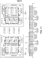
- FIG. 11 illustrates one embodiment of the flexible multi-carrier transceiver architecture in multi-carrier wireless system 80 to support data transmission over guard sub-carriers.
- TXPHY1, TXRF1, RXPHY1 and RXRF1 are configured and controlled to process and transmit a first radio signal associated with frequency channels #1 having a RF carrier frequency of f 0 , which is the Primary Frequency Channel.
- TXPHY2, TXRF2, RXPHY2 and RXRF2 are configured and controlled to process and transmit a second radio signal associated with a number of guard sub-carriers having a RF carrier frequency of f 0,1 , which is the Subsidiary Frequency Channel in between adjacent frequency channels #1 and #2.
- TXPHY3, TXRF3, RXPHY3 and RXRF3 are configured and controlled to process and transmit a third radio signal associated with frequency channels #2 having a RF carrier frequency of f 2 , which is the Secondary Frequency Channel.
- TXPHY4, TXRF4, RXPHY4 and RXRF4 are configured and controlled to process and transmit a fourth radio signal associated with a number of guard sub-carriers having a RF carrier frequency of f 2,3 , which is the Subsidiary Frequency Channel in between adjacent frequency channels #3 and #4.
- f 2,3 the Subsidiary Frequency Channel in between adjacent frequency channels #3 and #4.
- implementation method #1 is used because physical layer entities TXPHY1-TXPHY3 and RXPHY1-RXPHY3 and RF entities TXRF1-TXRF3 and RXRF1-RXRF3 are depicted as three separate baseband hardware modules and three independent narrow-band RF filters.
- those physical layer entities and RF entities may be implemented by using one single baseband hardware module and one wide-band RF filer.
- TXPHY1-TXPHY3, RXPHY1-RXPHY3 and TXRF1-TXRF3, RXRF1-RXRF3 may be implemented by sharing one single baseband hardware module (TXMOD or RXMOD), which utilizes one single FFT and one wide-band RF filter to generate and transmit/receive three OFDMA radio signals in parallel.
- the OFDMA radio signals generated using single baseband hardware module are equivalent to the OFDMA radio signals generated by three separate baseband hardware modules having corresponding RF carrier frequencies.
- part of the RF entities i.e., antennas
- Figure 12 illustrates another example of the flexible transceiver architecture to support multi-carrier operation.
- a serving base station BS it supports all RF carriers for serving different mobile stations (MS1-MS3).
- each mobile station may support only single-carrier transmission (e.g. MS1), multi-carrier transmission over contiguous frequency channels (e.g. MS2), or multi-carrier transmission over non-contiguous carriers (e.g. MS3).
- a mobile station that supports two contiguous 10MHz frequency channels e.g. MS2
- one example to implement its transceiver hardware is to utilize a single 2048 FFT and a 20MHz bandwidth RF filter to transmit 2x10MHz OFDMA signals through two adjacent frequency channels.
- the overlapped sub-carriers are always aligned and the mobile station can easily transmit radio signals over the guard sub-carriers between the two adjacent frequency channels.
- a method comprising:
- the identified guard sub-carriers are originally reserved for no data transmission if not aligned, and wherein the identified guard sub-carriers are orthogonal to normal data sub-carriers.
- the method further comprising: allocating guard sub-carriers to be utilized for data transmission, wherein a reference signal is periodically transmitted over the utilized guard sub-carriers.
- the identified guard sub-carriers are aggregated into a subsidiary frequency channel, and wherein a MAC layer indication indicates the support of data transmission over the subsidiary frequency channel.
- an aspect of the invention is a multi-carrier wireless device (MS23, BS22), comprising:
- the identified guard sub-carriers are originally reserved for no data transmission if not aligned, and wherein the identified guard sub-carriers are orthogonal to normal data sub-carriers.
- same physical resource unit size is used for the identified guard sub-carriers as well as normal data sub-carriers.
- a reference signal is periodically transmitted over allocated guard sub-carriers that are utilized for data transmission.
- the identified guard sub-carriers are aggregated into a subsidiary frequency channel, and wherein a MAC layer indication indicates the support of data transmission over the subsidiary frequency channel.
Landscapes
- Engineering & Computer Science (AREA)
- Signal Processing (AREA)
- Computer Networks & Wireless Communication (AREA)
- Power Engineering (AREA)
- Mobile Radio Communication Systems (AREA)
- Radio Transmission System (AREA)
Abstract
Description
- This application claims priority under 35 U.S.C. §119 from
U.S. Provisional Application Number 61/078,535 - The disclosed embodiments relate generally to wireless network communications, and, more particularly, to data communication over guard sub-carriers and flexible radio frequency transceiver architecture in multi-carrier OFDM systems.
- In current wireless communications systems, 5MHz∼10MHz radio bandwidths are typically used for up to 100Mbps peak transmission rate. Much higher peak transmission rate is required for next generation wireless systems. For example, 1Gbps peak transmission rate is required by ITU-R for IMT-Advanced systems such as the 4th generation ("4G") mobile communications systems. The current transmission technologies, however, are very difficult to perform 100bps/Hz transmission spectrum efficiency. In the foreseeable next few years, only up to 15bps/Hz transmission spectrum efficiency can be anticipated. Therefore, much wider radio bandwidths (i.e., at least 40MHz) will be necessary for next generation wireless communications systems to achieve 1Gbps peak transmission rate.
- Orthogonal Frequency Division Multiplexing (OFDM) is an efficient multiplexing scheme to perform high transmission rate over frequency selective channel without the disturbance from inter-carrier interference. There are two typical architectures to utilize much wider radio bandwidth for OFDM system. In a traditional OFDM system, a single radio frequency (RF) carrier is used to carry one wideband radio signal, and in an OFDM multi-carrier system, multiple RF carriers are used to carry multiple narrower band radio signals. An OFDM multi-carrier system has various advantages as compared to a traditional OFDM system such as easier backward compatibility, better reuse on legacy single-carrier hardware design, more mobile station hardware flexibility, and lower Peak to Average Power Ratio (PAPR) for uplink transmission. Thus, OFDM multi-carrier systems have become the baseline system architecture in IEEE 802.16m and 3GPP LTE-Advanced draft standards to fulfill system requirements.
WO 2008/118429 A1 discloses an example of typical multi-carrier OFDM or OFDMA bandwidth allocation with the guard subcarriers.
JP 2002 290 364 A -
Figure 1 (Prior Art) illustrates a typical architecture to utilize much wider radio bandwidth for OFDMmulti-carrier system 11. In OFDMmulti-carrier system 11, multiple RF carriers are used to carry multiple radio signals with narrower bandwidth (called narrower band radio signal). In the example ofFigure 1 , the total radio bandwidth of OFDMmulti-carrier system 11 is 40 MHz, and four RF carriers #1-#4 are used to carry four narrower band radio signals #1-#4, each transmitted through a corresponding 10MHz frequency channel #1-#4 (i.e., 10MHz Bandwidth, 1024FFT). For each RF carrier, the overall radio bandwidth is further partitioned into a large number of sub-carriers, which are closely spaced and orthogonal to each other for data transmission. When there are contiguous frequency channels used for data transmission, sub-carriers in between adjacent frequency channels may be overlap with each other. Therefore, overlapping sub-carriers located in between adjacent frequency channels are typically reserved as guard sub-carriers to prevent signal interference. - As illustrated in
Figure 1 , at both end of each frequency channel, a certain number of sub-carriers are reserved as NULL sub-carriers such that they are not used for data transmission. However, if both adjacent frequency channels are controlled and managed by the same base station, then it is not necessary to have those overlapping sub-carriers in between adjacent frequency channels to be reserved as guard sub-carriers. Instead, the guard sub-carriers in between adjacent frequency channels may be used for data transmission such that overall system throughput can be increased. For example, in IEEE 802.16m wireless communications systems, allowing data transmission over guard sub-carriers can increase system throughput by 2.08% for two contiguous 10MHz frequency channels, by 2.77% for three contiguous 10MHz frequency channels, and by 3.125% for four contiguous 10MHz frequency channels. It is thus desirable to enable data transmission over guard sub-carriers to increase overall system throughput and peak transmission rate. - In a first novel aspect, a method of data transmission over guard sub-carriers is provided in a multi-carrier OFDM system. Adjacent radio frequency (RF) carriers are used to carry radio signals transmitted through adjacent frequency channels. A plurality of guard sub-carriers between adjacent frequency channels are aligned and identified for data transmission in a pre-defined physical resource unit. The identified guard sub-carriers do not overlap with normal data sub-carriers of the radio signals transmitted through the adjacent frequency channels. At least one of the identified guard sub-carriers is reserved as NULL sub-carrier. Overall system throughput is increased by utilizing guard sub-carriers for data transmission.
- In one embodiment, a serving base station periodically transmits a reference signal over the guard sub-carriers that are utilized for data transmission. The use of the reference signal saves overhead on MAC message indication and provides flexibility for various guard sub-carrier allocation scenarios. In another embodiment, a Subsidiary Carrier consisting of aggregated guard sub-carriers utilized for data transmission is defined. By defining the Subsidiary Carrier, the serving base station may use a simple MAC layer indication to indicate whether guard sub-carriers are supported for data transmission with a particular mobile station.
- In a second novel aspect, a flexible multi-carrier transceiver architecture is provided in a multi-carrier OFDM system. Different multi-carrier and/or MIMO/SISO data transmission schemes are implemented by adaptively reconfigure same hardware modules including a common MAC layer module, an adaptive multi-carrier controller, multiple physical layer entities, and multiple RF entities. In a first embodiment, a single-carrier 4x4 MIMO data transmission scheme is supported; in a second embodiment, a multi-carrier (two RF carriers) 2x2 MIMO data transmission scheme is supported; and in a third embodiment, a multi-carrier (four RF carriers) SISO data transmission scheme is supported. The number of antennas for MIMO transmission over each frequency channel is the total number of RF entities divided by the number of supported active frequency channels.
- Furthermore, the flexible multi-carrier transceiver architecture can be used to support data transmission over guard sub-carriers. In one embodiment, a mobile station supports two contiguous 10MHz frequency channels. In one example, its transceiver hardware is implemented by utilizing two 1024 FFTs and two 10MHz bandwidth RF filters to transmit and receive 2x10MHz OFDMA signals through two adjacent frequency channels. In another example, its transceiver hardware is implemented by utilizing a single 2048 FFT and one 20MHz bandwidth RF filer to transmit and receive 2x10MHz OFDMA signals through two adjacent frequency channels. Under the second implementation, the overlapped sub-carriers are always aligned and the mobile station can easily transmit/receive radio signals over the guard sub-carriers between the two adjacent frequency channels.
- Other embodiments and advantages are described in the detailed description below. This summary does not purport to define the invention. The invention is defined by the claims.
- The accompanying drawings, where like numerals indicate like components, illustrate embodiments of the invention.
-
Figure 1 (Prior Art) illustrates a typical architecture to utilize much wider radio bandwidth for a multi-carrier OFDM system. -
Figure 2 illustrates a method of data transmission over guard sub-carriers in a multi-carrier wireless system in accordance with a first novel aspect. -
Figure 3 illustrates a method of aligning and indentifying guard sub-carriers for data transmission. -
Figure 4 illustrates a method of reserving a guard sub-carrier as a null sub-carrier when supporting data transmission. -
Figure 5 illustrates one embodiment of transmitting a reference signal over guard sub-carriers. -
Figure 6 illustrates another embodiment of transmitting a reference signal over guard sub-carriers. -
Figure 7 illustrates a Subsidiary Frequency Channel that consists of aggregated guard sub-carriers. -
Figure 8 illustrates one embodiment of the flexible multi-carrier transceiver architecture in a multi-carrier wireless system. -
Figure 9 illustrates a second embodiment of the flexible multi-carrier transceiver architecture in a multi-carrier wireless system. -
Figure 10 illustrates a third embodiment of the flexible multi-carrier transceiver architecture in a multi-carrier wireless system. -
Figure 11 illustrates one embodiment of the flexible multi-carrier transceiver architecture in a multi-carrier wireless system to support data transmission over guard sub-carriers. -
Figure 12 illustrates another example of the flexible transceiver architecture to support multi-carrier operation. - Reference will now be made in detail to some embodiments of the invention, examples of which are illustrated in the accompanying drawings.
-
Figure 2 illustrates a method of data transmission over guard sub-carriers in a multi-carrier Orthogonal Frequency Division Multiplexing (OFDM)wireless communications system 21 in accordance with a first novel aspect.Wireless system 21 comprises a multi-carrier base station BS22 and a multi-carrier mobile station MS23. BS22 comprises a multi-carrier radio frequency (RF)module 24 coupled to a plurality of antennas, supporting multiple RF carriers for data transmission. MS23 comprises amulti-carrier RF module 25 coupled to a plurality of antennas, supporting multiple RF carriers for data transmission. In the example ofFigure 2 , two contiguous radioRF carriers # 1 and #2 are used to carry tworadio signals # 1 and #2, each transmitted through a corresponding 10MHz frequency channel #1-#2 (i.e., 10MHz Bandwidth, 1024FFT) respectively. For each frequency channel, the overall radio bandwidth is further partitioned into a large number of sub-carriers, which are closely spaced and orthogonal to each other for data transmission over each radio signal. As illustrated inFigure 2 , in multi-carrierOFDM wireless system 21, data streams are communicated between BS22 and MS23 using a pre-defined physical resource unit (PRU) 26, comprising a number of consecutive sub-carriers in frequency domain and a number of consecutive OFDM symbols in time domain. Those sub-carriers used for data transmission are referred to as normal data sub-carriers. - When there are contiguous RF carriers (e.g.,
RF carriers # 1 and #2) used for data transmission, sub-carriers located at both end of each frequency channel may be overlap with each other. To prevent signal interference, those sub-carriers are reserved as guard sub-carriers. Typically, guard sub-carriers are configured as NULL sub-carriers and cannot be used for data transmission. In one novel aspect, with more details described below with respect toFigure 3 , a certain number of the originally reserved guard sub-carriers are aligned and then identified to support data transmission using a pre-defined PRU. In the example ofFigure 2 ,PRU 26 comprises eighteen consecutive sub-carriers and six consecutive OFDM symbols. The same PRU size is used for data transmission over normal data sub-carriers as well as the identified guard sub-carriers. In addition, the same pilot pattern designed for normal data sub-carriers can also be used for the identified guard sub-carriers. -
Figure 3 illustrates a method of aligning and indentifying guard sub-carriers for data transmission inwireless system 21. As illustrated inFigure 3 , the overlapped guard sub-carriers between adjacentfrequency channels # 1 and #2 can be utilized for data transmission only if the sub-carriers ofradio signal # 1 transmitted throughfrequency channel # 1 are well aligned with the sub-carriers of radio signals transmitted through adjacent frequency channels (e.g.,radio signal # 2 transmitted through frequency channel #2) in frequency domain. Alignment can be achieved by applying a frequency offset over the RF carrier frequency of the radio signals. In the example ofFigure 3 , a 3.128KHz frequency offset is applied over the RF carrier frequency ofradio signal # 2 to make it shifted from the center frequency offrequency channel # 2 in order to align the overlapped guard sub-carriers of the radio signal transmitted through two adjacent 10MHz frequency channels. For more details on sub-carrier alignment, see related documents such as IEEE 802.16m-09/0267r1, "Text Input for Sub-Carrier Alignment based on P802.16m SDD", the subject matter of which is incorporated herein by reference. - After sub-carrier alignment, additional computation is performed such that only those guard sub-carriers that do not overlap with normal data sub-carriers are available for data transmission. In the example of
Figure 3 , each frequency channel comprises 864 (2 * 432) sub-carriers, which is partitioned into 48 (2 * 24) PRUs for data transmission. In this particular example, forty-seven guard sub-carriers in between the two adjacentfrequency channels # 1 and #2 do not overlap with normal data sub-carriers ofradio signal # 1 and #2. Those guard sub-carriers are identified bywireless system 21 as sub-carriers that can be used for data transmission. There are many nominal frequency channel bandwidths considered by IEEE 802.16m, including 5, 7, 8.75, 10 and 20MHz. Each combination of different bandwidth for adjacent frequency channels will result in different number of available guard sub-carriers for data transmission. It will thus result in high overhead ifwireless system 21 needs to explicitly signaling all the possible numbers of available guard sub-carrier under different combinations. - In accordance with the first novel aspect, the identified guard sub-carriers are partitioned into PRUs for data transmission. The same PRU size and pilot pattern designed for normal data sub-carriers can be reused for the identified guard sub-carriers. By reusing the same PRU size and pilot pattern, certain physical layer design such as channel estimation algorithm can also be reused. Furthermore, hardware complexity and signaling overhead is reduced because signaling can be performed in a predefine PRU size rather than in an arbitrary number.
-
Figure 4 illustrates a method of reserving at least one guard sub-carrier as NULL sub-carrier when supporting data transmission. There are two different hardware methods to implement data transmission over two contiguous frequency channels. Inmethod # 1, two separate physical layer modules (PHY# 1 and PHY#2) are used as the baseband hardware modules to utilize two 1024 FFT and two 10MHz RF filters to transmit/receive 2x10MHz OFDMA radio signals over two adjacent frequency channels. The RF carrier frequency of each frequency channel, referred to as direct current (DC) sub-carrier, needs to be reserved as NULL sub-carrier to avoid signal interference. Inmethod # 2, one single physical layer module (PHY) is shared as the baseband hardware module to utilize a 2048 FFT and a 20MHz bandwidth RF filter to transmit/receive 2x10MHz OFDMA radio signals in parallel over two adjacent frequency channels. Similar tomethod # 1, The RF carrier frequency (DC sub-carrier) undermethod # 2 also needs to be reserved as NULL sub-carrier to avoid signal interference. Inmethod 2, however, the DC sub-carrier belongs to one of the identified guard sub-carriers. Thus, to ensure proper data transmission, at least one indentified guard sub-carrier needs to be reserved as NULL sub-carrier. -
Figures 5-6 illustrate two examples of transmitting a reference signal over guard sub-carriers. Among guard sub-carries available for data transmission, the serving base station still need to communicate with the mobile stations on which guard sub-carriers are actually allocated and utilized for data transmission. Using a MAC message to indicate such allocation explicitly may result in high overhead. Instead, the serving base station periodically transmits a reference signal (e.g., preamble) over the guard sub-carriers that are used for data transmission such that the mobile stations may detect the location of the utilized guard sub-carriers. In the example ofFigure 5 , all identified guard subcarriers are utilized for data transmission. In the example ofFigure 6 , only some of the identified guard sub-carriers are utilized for data transmission. In both examples, the serving base station periodically transmits a reference signal over the utilized guard sub-carriers to indicate the location of the utilized guard sub-carriers. The use of the reference signal saves overhead on MAC message indication and provides flexibility for various allocation scenarios. -
Figure 7 illustrates a Subsidiary Frequency Channel that consists of aggregated guard sub-carriers. In the example ofFigure 7 ,Frequency channels # 1 is configured as a Primary Frequency Channel, which includes all control channel configuration for synchronization, broadcast, multicast and unicast of control signals. Frequency channel #2-#4 are configured as Secondary Frequency Channels, which include only essential control channel configuration. The identified guard sub-carriers in between contiguous frequency channels are aggregated and identified as Subsidiary Frequency Channel, which may have the same control channel configuration as the Secondary Frequency Channels. By defining the Subsidiary Frequency Channels, the serving base station may use a simple MAC layer indication (e.g., a single bit) to indicate whether guard sub-carriers are used for data transmission with a particular mobile station. If data transmission over guard sub-carriers is supported, then the serving base station may periodically transmits a reference signal over the utilized guard sub-carriers to indicate their locations, as illustrated above with respect toFigures 5 and 6 . - In a second novel aspect, a flexible multi-carrier transceiver architecture is provided to support multi-carrier transmission in wireless systems.
Figure 8 illustrates one embodiment of the flexible multi-carrier transceiver architecture in amulti-carrier wireless system 80.Multi-carrier system 80 comprises awireless transmitter 81 for data transmission and awireless receiver 85 for data reception.Transmitter 81 comprises a commonMAC control entity 82, an adaptivemulti-carrier controller 83, amultiplexer 84, a plurality of transmitting physical layer entities TXPHY1-TXPHY4, and a plurality of transmitting RF entities TXRF1-TXRF4 coupled to a plurality of antennas to transmit radio signals. Similarly,receiver 85 comprises a commonMAC control entity 86, an adaptivemulti-carrier controller 87, amultiplexer 88, a plurality of receiving physical layer entities RXPHY1-RXPHY4, and a plurality of receiving RF entities RXRF1-RXRF4 coupled to a plurality of antennas to receive radio signals. - For
transmitter 81,common MAC controller 82 configures adaptivemulti-carrier controller 83 and transmitting physical layer entities TXPHY1-TXPHY4 to process radio signals carried by a number of RF carriers and transmitted through a corresponding frequency channel. In addition, adaptivemulti-carrier controller 83 controls the RF carrier frequencies of transmitting RF entities TXRF1-TXRF4; each transmitting RF entity is operable to transmit a radio signal through the corresponding frequency channel. Similarly, forreceiver 85,common MAC controller 86 configures adaptivemulti-carrier controller 87 and receiving physical layer entities RXPHY1-RXPHY4 to process radio signals carried by a number of RF carriers and received through a corresponding frequency channel. In addition, adaptivemulti-carrier controller 87 controls the RF carrier frequencies of receiving RF entities RXRF1-RXRF4; each receiving RF entity is operable to receive a radio signal through the corresponding frequency channel. - In the example of
Figure 8 , one transmitting physical layer entity TXPHY1 is enabled and coupled to all transmitting RF entities TXRF1-TXRF4 throughmultiplexer 84. TXPHY1 is configured to process a first radio signal carried byRF carrier # 1 and transmitted through one activefrequency channel # 1.Frequency channel # 1 has a RF carrier frequency of f0. In addition, adaptivemulti-carrier controller 83 controls each transmitting RF entities TXRF1-TXRF4 to transmit the first radio signal throughfrequency channel # 1 with RF carrier frequency f0. Similar configuration and control are applied for receiving physical layer entity RXPH1 and four receiving RF entities RXRF1-RXRF4. Using such configuration and control, a single-carrier (RF carrier #1) 4x4 multiple-input multiple-output (MIMO) data transmission scheme is supported inmulti-carrier wireless system 80. -
Figure 9 illustrates a second embodiment of the flexible multi-carrier transceiver architecture inmulti-carrier wireless system 80. In the example ofFigure 9 , two transmitting physical layer entities TXPHY1 and TXPHY2 are enabled and coupled to all transmitting RF entities TXRF1-TXRF4 throughmultiplexer 84. TXPHY1 is configured to process a first radio signal carried byRF carrier # 1 and transmitted through activefrequency channel # 1, and TXPHY2 is configured to process a second radio signal carried byRF carrier # 2 and transmitted through activefrequency channel # 2.Frequency channel # 1 has a RF carrier frequency of f0 andfrequency channel # 2 has a RF carrier frequency of f1. In addition, adaptivemulti-carrier controller 83 controls TXRF1-TXRF2 to transmit the first radio signal through activefrequency channel # 1 with RF carrier frequency f0, and controls TXRF3-TXRF4 to transmit the second radio signal through activefrequency channel # 2 with RF carrier frequency f1. Similar configuration and control are applied for receiving physical layer entity RXPHY1, RXPHY2, and four receiving RF entities RXRF1-RXRF4. Using such configuration and control, a multi-carrier (RF carrier # 1 and RF carrier #2) 2x2 MIMO data transmission scheme is supported inmulti-carrier wireless system 80. -
Figure 10 illustrates a third embodiment of the flexible multi-carrier transceiver architecture inmulti-carrier wireless system 80. In the example ofFigure 10 , all four transmitting physical layer entities TXPHY1-TXPHY4 are enabled and coupled to all four transmitting RF entities TXRF1-TXRF4 throughmultiplexer 84. TXPHY1-TXPHY4 are configured to process four radio signals carried by four different RF carriers (RF carriers #1-#4) and transmitted through four active frequency channels #1-#4 respectively. Frequency channels #1-#4 each has a RF carrier frequency of f0-f3 respectively. In addition, adaptivemulti-carrier controller 83 controls TXRF1-TXRF4 to transmit the four radio signals through active frequency channels #1-4 with the RF carrier frequencies of f0-f3 respectively. Similar configuration and control are applied for all four receiving physical layer entity RXPHY1-RXPHY4 and all four receiving RF entities RXRF1-RXRF4. Using the above-described configuration and control, a multi-carrier (RF carriers #1-#4) single-input single-output (SISO) data transmission scheme is supported inmulti-carrier wireless system 80. - In accordance with the second novel aspect of the flexible multi-carrier transceiver architecture,
wireless system 80 can adaptively reconfigure the desirable data transmission scheme based on the negotiation between the transmitter and the receiver. The same hardware resource, including a MAC layer controller, multiple physical-layer baseband hardware modules, multiple RF transceivers, and multiple antennas, are shared to implement different combination of multi-carrier and/or MIMO/SISO data transmission schemes. The number of antennas to support MIMO transmission over each frequency channel is the total number of RF entities divided by the number of supported active frequency channels. - Furthermore, such flexible multi-carrier transceiver architecture can be used to support data transmission over guard sub-carriers.
Figure 11 illustrates one embodiment of the flexible multi-carrier transceiver architecture inmulti-carrier wireless system 80 to support data transmission over guard sub-carriers. In the example ofFigure 11 , TXPHY1, TXRF1, RXPHY1 and RXRF1 are configured and controlled to process and transmit a first radio signal associated withfrequency channels # 1 having a RF carrier frequency of f0, which is the Primary Frequency Channel. TXPHY2, TXRF2, RXPHY2 and RXRF2 are configured and controlled to process and transmit a second radio signal associated with a number of guard sub-carriers having a RF carrier frequency of f0,1, which is the Subsidiary Frequency Channel in between adjacentfrequency channels # 1 and #2. TXPHY3, TXRF3, RXPHY3 and RXRF3 are configured and controlled to process and transmit a third radio signal associated withfrequency channels # 2 having a RF carrier frequency of f2, which is the Secondary Frequency Channel. TXPHY4, TXRF4, RXPHY4 and RXRF4 are configured and controlled to process and transmit a fourth radio signal associated with a number of guard sub-carriers having a RF carrier frequency of f2,3, which is the Subsidiary Frequency Channel in between adjacentfrequency channels # 3 and #4. Thus, the same hardware modules and components used for multi-carrier and/or MIMO/SISO data transmission can also be used for data transmission over guard sub-carriers. There are no restrictions on each carrier location to be used, and the system can flexibly enable or disable each carrier based on system condition such as loading and traffic demand. - As illustrated above with respect to
Figure 4 , there are two different hardware methods to implement data transmission over two contiguous frequency channels. In the example ofFigure 11 ,implementation method # 1 is used because physical layer entities TXPHY1-TXPHY3 and RXPHY1-RXPHY3 and RF entities TXRF1-TXRF3 and RXRF1-RXRF3 are depicted as three separate baseband hardware modules and three independent narrow-band RF filters. In consistent with theimplementation method # 2 illustrated above with respect toFigure 4 , however, those physical layer entities and RF entities may be implemented by using one single baseband hardware module and one wide-band RF filer. For example, TXPHY1-TXPHY3, RXPHY1-RXPHY3 and TXRF1-TXRF3, RXRF1-RXRF3 may be implemented by sharing one single baseband hardware module (TXMOD or RXMOD), which utilizes one single FFT and one wide-band RF filter to generate and transmit/receive three OFDMA radio signals in parallel. The OFDMA radio signals generated using single baseband hardware module are equivalent to the OFDMA radio signals generated by three separate baseband hardware modules having corresponding RF carrier frequencies. In addition, part of the RF entities (i.e., antennas) can be shared for both implementation methods. -
Figure 12 illustrates another example of the flexible transceiver architecture to support multi-carrier operation. For a serving base station BS, it supports all RF carriers for serving different mobile stations (MS1-MS3). On the other hand, each mobile station may support only single-carrier transmission (e.g. MS1), multi-carrier transmission over contiguous frequency channels (e.g. MS2), or multi-carrier transmission over non-contiguous carriers (e.g. MS3). For a mobile station that supports two contiguous 10MHz frequency channels (e.g. MS2), one example to implement its transceiver hardware is to utilize a single 2048 FFT and a 20MHz bandwidth RF filter to transmit 2x10MHz OFDMA signals through two adjacent frequency channels. Using this implementation method, the overlapped sub-carriers are always aligned and the mobile station can easily transmit radio signals over the guard sub-carriers between the two adjacent frequency channels. - Although the present invention has been described in connection with certain specific embodiments for instructional purposes, the present invention is not limited thereto. Accordingly, various modifications, adaptations, and combinations of various features of the described embodiments can be practiced without departing from the scope of the invention as set forth in the claims.
- Further aspects of the invention are
A method, comprising: - (a) aligning a plurality of guard sub-carriers between adjacent frequency channels in a multi-carrier OFDM wireless system to offset a frequency shift of the guard sub-carriers, wherein adjacent radio frequency carriers are used to carry radio signals transmitted through the adjacent frequency channels;
- (b) identifying a number of guard sub-carriers among the plurality of guard sub-carriers available for data transmission in a pre-defined physical resource unit, wherein the identified guard sub-carriers do not overlap with normal data sub-carriers of the radio signals transmitted through the adjacent frequency channels; and
- (c) reserving one or more identified guard sub-carriers such that the reserved one or more identified guard sub-carriers is not used for data transmission.
- In a preferred embodiment of the method wherein the identified guard sub-carriers are originally reserved for no data transmission if not aligned, and wherein the identified guard sub-carriers are orthogonal to normal data sub-carriers.
- In a preferred embodiment of the method wherein same physical resource unit size is used for the identified guard sub-carriers as well as for normal data sub-carriers.
- In a preferred embodiment of the method wherein same pilot pattern is used for the identified guard sub-carriers as well as for normal data sub-carriers.
- In a preferred embodiment of the method further comprising:
allocating guard sub-carriers to be utilized for data transmission, wherein a reference signal is periodically transmitted over the utilized guard sub-carriers. - In a preferred embodiment of the method wherein the identified guard sub-carriers are aggregated into a subsidiary frequency channel, and wherein a MAC layer indication indicates the support of data transmission over the subsidiary frequency channel.
- Also an aspect of the invention is a multi-carrier wireless device (MS23, BS22), comprising:
- a plurality of antennas, wherein each antenna receives from and transmit to radio signals carried by adjacent radio frequency carriers and transmitted through adjacent frequency channels in a multi-carrier OFDM wireless system; and
- a multi-carrier RF module (24,25) coupled to the plurality of antennas, wherein a number of overlapped guard sub-carriers of the radio signal transmitted through the adjacent frequency channels are aligned and identified for data transmission in a pre-defined physical resource unit, wherein the identified guard sub-carriers do not overlap with normal data sub-carriers of the radio signals transmitted through the adjacent frequency channels, and wherein at least one or more identified guard sub-carriers is reserved for no data transmission.
- In a preferred embodiment of the multi-carrier wireless device wherein the identified guard sub-carriers are originally reserved for no data transmission if not aligned, and wherein the identified guard sub-carriers are orthogonal to normal data sub-carriers.
- In a preferred embodiment of the multi-carrier wireless device, same physical resource unit size is used for the identified guard sub-carriers as well as normal data sub-carriers.
- In a preferred embodiment of the multi-carrier wireless device, wherein same pilot pattern is used for the identified guard sub-carriers as well as for normal data sub-carriers.
- In a preferred embodiment of the multi-carrier wireless device, wherein a reference signal is periodically transmitted over allocated guard sub-carriers that are utilized for data transmission.
- In a preferred embodiment of the multi-carrier wireless device, wherein the identified guard sub-carriers are aggregated into a subsidiary frequency channel, and wherein a MAC layer indication indicates the support of data transmission over the subsidiary frequency channel.
Claims (13)
Applications Claiming Priority (4)
| Application Number | Priority Date | Filing Date | Title |
|---|---|---|---|
| US7853508P | 2008-07-07 | 2008-07-07 | |
| US12/459,720 US8891350B2 (en) | 2008-07-07 | 2009-07-06 | Method and apparatus of data transmission over guard sub-carriers in multi-carrier OFDM systems |
| PCT/CN2009/072677 WO2010003373A1 (en) | 2008-07-07 | 2009-07-07 | Method and apparatus of data transmission over guard sub-carriers in multi-carrier ofdm systems |
| EP09793848.4A EP2308206B8 (en) | 2008-07-07 | 2009-07-07 | Method and apparatus of data transmission over guard sub-carriers in multi-carrier ofdm systems |
Related Parent Applications (2)
| Application Number | Title | Priority Date | Filing Date |
|---|---|---|---|
| EP09793848.4A Division-Into EP2308206B8 (en) | 2008-07-07 | 2009-07-07 | Method and apparatus of data transmission over guard sub-carriers in multi-carrier ofdm systems |
| EP09793848.4A Division EP2308206B8 (en) | 2008-07-07 | 2009-07-07 | Method and apparatus of data transmission over guard sub-carriers in multi-carrier ofdm systems |
Publications (1)
| Publication Number | Publication Date |
|---|---|
| EP3435611A1 true EP3435611A1 (en) | 2019-01-30 |
Family
ID=41464347
Family Applications (2)
| Application Number | Title | Priority Date | Filing Date |
|---|---|---|---|
| EP18187496.7A Ceased EP3435611A1 (en) | 2008-07-07 | 2009-07-07 | Method and apparatus of data transmission over guard sub-carriers in multi-carrier ofdm systems |
| EP09793848.4A Active EP2308206B8 (en) | 2008-07-07 | 2009-07-07 | Method and apparatus of data transmission over guard sub-carriers in multi-carrier ofdm systems |
Family Applications After (1)
| Application Number | Title | Priority Date | Filing Date |
|---|---|---|---|
| EP09793848.4A Active EP2308206B8 (en) | 2008-07-07 | 2009-07-07 | Method and apparatus of data transmission over guard sub-carriers in multi-carrier ofdm systems |
Country Status (6)
| Country | Link |
|---|---|
| US (2) | US8891350B2 (en) |
| EP (2) | EP3435611A1 (en) |
| JP (2) | JP2011526446A (en) |
| CN (2) | CN101828369B (en) |
| TW (2) | TWI470961B (en) |
| WO (1) | WO2010003373A1 (en) |
Families Citing this family (41)
| Publication number | Priority date | Publication date | Assignee | Title |
|---|---|---|---|---|
| JP2011525758A (en) * | 2008-07-07 | 2011-09-22 | 聯發科技股▲ふん▼有限公司 | Data transmission / reception method and communication apparatus using the same in multiband orthogonal frequency division multiple access (OFDMA) communication system |
| US10141984B2 (en) | 2008-07-14 | 2018-11-27 | Marvell World Trade Ltd. | Multi-band transmission system |
| JP5168015B2 (en) * | 2008-07-31 | 2013-03-21 | 富士通モバイルコミュニケーションズ株式会社 | Radio base station apparatus and mobile radio terminal apparatus |
| KR101520708B1 (en) * | 2008-08-12 | 2015-05-15 | 엘지전자 주식회사 | An appratus and method for transceiving downlink control information |
| US20100172235A1 (en) * | 2009-01-06 | 2010-07-08 | Samsung Electronics Co., Ltd. | System and method for initialization of a scrambling sequence for a downlink reference signal |
| CN101873697A (en) * | 2009-04-25 | 2010-10-27 | 中兴通讯股份有限公司 | Resource mapping method |
| KR101785712B1 (en) | 2009-10-23 | 2017-10-17 | 한국전자통신연구원 | Method and apparatus for controlling transmissinon power in wlan system |
| US8958378B2 (en) * | 2010-03-02 | 2015-02-17 | Lg Electronics Inc. | Multicarrier based communication method and device |
| ES3040212T3 (en) * | 2010-03-12 | 2025-10-29 | Electronics & Telecommunications Res Inst | Method and apparatus for transmitting and receiving data in a mimo system |
| US9031003B2 (en) * | 2010-06-29 | 2015-05-12 | Lg Electronics Inc. | Terminal, the transmission power of which is limited in accordance with an adjacent channel interference ratio |
| CN102438320B (en) * | 2010-09-29 | 2015-03-11 | 电信科学技术研究院 | Downlink dispatching information configuring method and equipment |
| CN104113505B (en) * | 2010-09-30 | 2017-06-20 | 中国移动通信集团公司 | The method and terminal device of multi-carrier communications systems reduction interference |
| WO2012081921A2 (en) * | 2010-12-16 | 2012-06-21 | Lg Electronics Inc. | Method and apparatus for transmitting channel information in cognitive radio network and method and apparatus for performing channel switching |
| US9071399B2 (en) * | 2012-08-29 | 2015-06-30 | Intel Mobile Communications GmbH | Method for operating a transceiver circuit and transceiver circuit |
| DK3478014T3 (en) | 2012-12-13 | 2021-08-30 | Ericsson Telefon Ab L M | DESIGN OF PHYSICAL CHANNEL FOR NETWORK SUPPORTED D2D |
| US9865783B2 (en) | 2013-09-09 | 2018-01-09 | Luminus, Inc. | Distributed Bragg reflector on an aluminum package for an LED |
| US9769796B2 (en) * | 2013-10-08 | 2017-09-19 | Microsoft Technology Licensing, Llc | Radio channel utilization |
| CN104885539B (en) * | 2013-12-27 | 2019-10-25 | 华为技术有限公司 | Narrow-band system data transmission method and device |
| US20150303741A1 (en) * | 2014-04-18 | 2015-10-22 | Qualcomm Incorporated | Wireless energy transmission |
| US10594652B2 (en) * | 2014-10-16 | 2020-03-17 | Qualcomm Incorporated | Wireless communication utilizing a unified air interface |
| US10264554B2 (en) * | 2014-10-16 | 2019-04-16 | Lg Electronics Inc. | Method and device for allocating wireless resources in bandwidths of different sizes in wireless LAN |
| CN107113830B (en) * | 2014-11-01 | 2020-11-20 | Lg电子株式会社 | Method and apparatus for allocating resource units in a wireless LAN |
| ES2796183T3 (en) * | 2015-02-25 | 2020-11-26 | Lg Electronics Inc | Signal transmission method and device using a resource unit including a plurality of subcarriers |
| BR112017016444A2 (en) | 2015-03-11 | 2018-04-10 | Halliburton Energy Services Inc | assembly, system and antenna for indoor communication using surface waves. |
| AU2015385795B2 (en) * | 2015-03-11 | 2018-12-20 | Halliburton Energy Services, Inc. | Downhole communications using frequency guard bands |
| US10129873B2 (en) | 2015-04-08 | 2018-11-13 | Qualcomm Incorporated | Non-contiguous channel allocation and bonding for wireless communication networks |
| US10244531B2 (en) * | 2015-09-03 | 2019-03-26 | Qualcomm Incorporated | Re-channelization of sub-carriers |
| EP3142285B1 (en) * | 2015-09-10 | 2019-08-07 | Kyynel Oy | Communication method, apparatus and computer program |
| WO2017161042A1 (en) * | 2016-03-16 | 2017-09-21 | Qualcomm Incorporated | Tone plan adaptation for channel bonding in wireless communication networks |
| US10349440B2 (en) * | 2016-04-11 | 2019-07-09 | Qualcomm Incorporated | Feedback mechanism to activate and/or deactivate a semi-persistent scheduling grant |
| US10945274B2 (en) * | 2016-05-13 | 2021-03-09 | Huawei Technologies Co., Ltd. | System and method for bandwidth utilization |
| US10171214B2 (en) | 2016-09-29 | 2019-01-01 | At&T Intellectual Property I, L.P. | Channel state information framework design for 5G multiple input multiple output transmissions |
| US10602507B2 (en) | 2016-09-29 | 2020-03-24 | At&T Intellectual Property I, L.P. | Facilitating uplink communication waveform selection |
| US10644924B2 (en) | 2016-09-29 | 2020-05-05 | At&T Intellectual Property I, L.P. | Facilitating a two-stage downlink control channel in a wireless communication system |
| US10206232B2 (en) | 2016-09-29 | 2019-02-12 | At&T Intellectual Property I, L.P. | Initial access and radio resource management for integrated access and backhaul (IAB) wireless networks |
| US10158555B2 (en) | 2016-09-29 | 2018-12-18 | At&T Intellectual Property I, L.P. | Facilitation of route optimization for a 5G network or other next generation network |
| CN109937546B (en) | 2016-11-09 | 2022-06-07 | 瑞典爱立信有限公司 | Link adaptation for simultaneous OFDMA signaling and non-OFDMA signaling |
| US10355813B2 (en) | 2017-02-14 | 2019-07-16 | At&T Intellectual Property I, L.P. | Link adaptation on downlink control channel in a wireless communications system |
| CN108540418B (en) * | 2017-03-06 | 2022-05-03 | 中兴通讯股份有限公司 | Data modulation method and device for edge sub-band |
| US11265879B2 (en) * | 2019-07-05 | 2022-03-01 | Qualcomm Incorporated | Group component carrier based updates |
| EP4152708B1 (en) * | 2020-05-27 | 2024-05-15 | Huawei Technologies Co., Ltd. | Communication method and communication device |
Citations (4)
| Publication number | Priority date | Publication date | Assignee | Title |
|---|---|---|---|---|
| JP2002290364A (en) | 2001-03-22 | 2002-10-04 | Fujitsu General Ltd | OFDM transmission / reception method and apparatus |
| US20050243954A1 (en) * | 2003-04-07 | 2005-11-03 | Shaolin Li | Multi-antenna wireless data processing system |
| EP1715643A2 (en) * | 2005-04-21 | 2006-10-25 | Broadcom Corporation | Rf transceiver having adaptive modulation |
| WO2008118429A1 (en) | 2007-03-23 | 2008-10-02 | Zte (Usa) Inc. | Scalable ofdm and ofdma bandwidth allocation in communication systems |
Family Cites Families (47)
| Publication number | Priority date | Publication date | Assignee | Title |
|---|---|---|---|---|
| JP2000261403A (en) | 1999-03-04 | 2000-09-22 | Sony Corp | Transmission device and method, and providing medium |
| US7133352B1 (en) | 1999-09-20 | 2006-11-07 | Zion Hadad | Bi-directional communication channel |
| US7418043B2 (en) | 2000-07-19 | 2008-08-26 | Lot 41 Acquisition Foundation, Llc | Software adaptable high performance multicarrier transmission protocol |
| EP1204283A1 (en) * | 2000-11-06 | 2002-05-08 | Telefonaktiebolaget L M Ericsson (Publ) | Cellular radio network reusing frequencies |
| JP3800503B2 (en) | 2001-04-24 | 2006-07-26 | 日本ビクター株式会社 | Multi-carrier signal generation method |
| JP2003078426A (en) * | 2001-08-31 | 2003-03-14 | Nec Corp | Method for correcting frequency of portable terminal device |
| JP4245330B2 (en) | 2001-10-31 | 2009-03-25 | パナソニック株式会社 | Wireless transmission apparatus and wireless communication method |
| AU2003903826A0 (en) | 2003-07-24 | 2003-08-07 | University Of South Australia | An ofdm receiver structure |
| US7933343B2 (en) | 2002-12-30 | 2011-04-26 | Motorola Mobility, Inc. | Enhanced OFDM by use of alternating polarization states |
| US20040228270A1 (en) * | 2003-05-13 | 2004-11-18 | Hou-Shin Chen | Method of processing an OFDM signal and OFDM receiver using the same |
| US7372907B2 (en) * | 2003-06-09 | 2008-05-13 | Northrop Grumman Corporation | Efficient and flexible oversampled filterbank with near perfect reconstruction constraint |
| JP4425857B2 (en) | 2003-06-27 | 2010-03-03 | 三菱電機株式会社 | Transmitter, receiver and wireless communication device |
| JP4000123B2 (en) | 2004-03-15 | 2007-10-31 | 株式会社東芝 | Wireless transmission apparatus and method |
| US7046617B2 (en) | 2004-03-22 | 2006-05-16 | Motorola, Inc. | Method and apparatus for an enhanced OFDM system |
| US7177662B2 (en) * | 2004-04-02 | 2007-02-13 | Broadcom Corporation | Multimode wireless communication device |
| WO2006000614A1 (en) | 2004-06-28 | 2006-01-05 | Nokia Corporation | Fft carrier frequency offset estimation for ofdm signal |
| KR100640581B1 (en) | 2004-07-02 | 2006-10-31 | 삼성전자주식회사 | Orthogonal Frequency Division Multiple Access System and Frequency Offset Control Method for Controlling Frequency Offset of Access User in Uplink Communication |
| US7742388B2 (en) | 2004-07-20 | 2010-06-22 | Daniel Shearer | Packet generation systems and methods |
| WO2006092852A1 (en) | 2005-03-02 | 2006-09-08 | Fujitsu Limited | Ofdm communication system and ofdm communication method |
| US8428001B2 (en) * | 2005-03-10 | 2013-04-23 | Qualcomm Incorporated | Timing corrections in a multi carrier system and propagation to a channel estimation time filter |
| WO2006102744A1 (en) * | 2005-03-30 | 2006-10-05 | Nortel Networks Limited | Systems and methods for ofdm channelization |
| KR100800692B1 (en) | 2005-04-11 | 2008-02-01 | 삼성전자주식회사 | Frequency offset estimator and method for orthogonal frequency division multiplexing system |
| JP2008536426A (en) | 2005-04-15 | 2008-09-04 | ノキア コーポレイション | Synchronization method in multi-carrier system using variable guard interval |
| US7480497B2 (en) * | 2005-06-29 | 2009-01-20 | Intel Corporation | Multicarrier receiver and method for carrier frequency offset correction and channel estimation for receipt of simultaneous transmissions over a multi-user uplink |
| JP4421524B2 (en) | 2005-06-30 | 2010-02-24 | 日本電信電話株式会社 | Wireless communication system and wireless communication method |
| US7738575B2 (en) | 2005-07-21 | 2010-06-15 | Realtek Semiconductor Corp. | Overlap-and-add with DC-offset correction |
| WO2007022430A2 (en) | 2005-08-18 | 2007-02-22 | Beceem Communications Inc. | Antenna virtualization in communication systems |
| BRPI0617044A2 (en) * | 2005-09-29 | 2011-07-12 | Interdigital Tech Corp | frequency-sharing, single-carrier multiple access system based on minimum beam formation |
| US20070091984A1 (en) * | 2005-10-24 | 2007-04-26 | Texas Instruments Incorporated | Dual-Carrier Modulation Decoder |
| EP1793548A1 (en) | 2005-12-02 | 2007-06-06 | Interuniversitair Microelektronica Centrum Vzw | Method for estimating and compensating carrier frequency offset and I/Q imbalance |
| WO2007103085A2 (en) | 2006-03-01 | 2007-09-13 | Interdigital Technology Corporation | Method and apparatus for calibration and channel state feedback to support transmit beamforming in a mimo system |
| EP1997282A1 (en) * | 2006-03-17 | 2008-12-03 | Samsung Electronics Co., Ltd. | Transmission/reception apparatus and method for supporting both high rate packet data transmission and orthogonal frequency division multiplexing transmission in a mobile communication system |
| JP2007274048A (en) | 2006-03-30 | 2007-10-18 | Fujitsu Ltd | Wireless communication apparatus and wireless unit |
| US7929912B2 (en) | 2006-04-04 | 2011-04-19 | Texas Instruments Incorporated | Apparatus for and method of Bluetooth and WiMAX coexistence in a mobile handset |
| EA013068B1 (en) * | 2006-06-16 | 2010-02-26 | Шарп Кабусики Кайся | Synchronization channel data structure in mobile communication system adopting a multicarrier communication scheme and a base station controlling over a cell containing a plurality of sectors |
| TW200810456A (en) * | 2006-06-21 | 2008-02-16 | Qualcomm Inc | Wireless resource allocation methods and apparatus |
| US8917674B2 (en) * | 2006-07-25 | 2014-12-23 | Broadcom Corporation | Method and system for content-aware mapping/error protection |
| US8102853B2 (en) | 2006-08-09 | 2012-01-24 | Samsung Electronics Co., Ltd. | System and method for wireless communication of uncompressed video having fixed size MAC header with an extension |
| JP4751799B2 (en) * | 2006-09-19 | 2011-08-17 | 株式会社エヌ・ティ・ティ・ドコモ | Data inflow control device and data inflow control method |
| WO2008056426A1 (en) * | 2006-11-10 | 2008-05-15 | Mitsubishi Electric Corporation | Mobile communication system, mobile station and base station |
| JP4274240B2 (en) | 2006-12-28 | 2009-06-03 | ブラザー工業株式会社 | Communication device |
| US9281917B2 (en) | 2007-01-03 | 2016-03-08 | Nokia Technologies Oy | Shared control channel structure |
| KR101301756B1 (en) * | 2007-02-09 | 2013-08-30 | 텔레콤 이탈리아 소시에떼 퍼 아찌오니 | Characterization of co-channel interference in a wireless communication system |
| KR101382894B1 (en) * | 2007-03-12 | 2014-04-08 | 엘지전자 주식회사 | Method for transmitting control information in multiple antenna system |
| US8045632B2 (en) * | 2007-04-18 | 2011-10-25 | Texas Instruments Incorporated | Systems and methods for dual-carrier modulation encoding and decoding |
| US9565001B2 (en) * | 2007-06-01 | 2017-02-07 | Texas Instruments Incorporated | Guard subcarrier placement in an OFDM symbol used for synchronization |
| US8259828B2 (en) | 2008-02-12 | 2012-09-04 | Mediatek Inc. | Sub-carrier alignment mechanism for OFDM multi-carrier systems |
-
2009
- 2009-07-06 US US12/459,720 patent/US8891350B2/en active Active
- 2009-07-07 TW TW101141728A patent/TWI470961B/en active
- 2009-07-07 JP JP2011515080A patent/JP2011526446A/en active Pending
- 2009-07-07 EP EP18187496.7A patent/EP3435611A1/en not_active Ceased
- 2009-07-07 WO PCT/CN2009/072677 patent/WO2010003373A1/en not_active Ceased
- 2009-07-07 CN CN2009800003863A patent/CN101828369B/en active Active
- 2009-07-07 CN CN201210328171.8A patent/CN102983954B/en active Active
- 2009-07-07 EP EP09793848.4A patent/EP2308206B8/en active Active
- 2009-07-07 TW TW098122908A patent/TWI408920B/en active
-
2013
- 2013-02-12 JP JP2013024225A patent/JP2013153445A/en active Pending
-
2014
- 2014-10-16 US US14/515,752 patent/US9967880B2/en active Active
Patent Citations (4)
| Publication number | Priority date | Publication date | Assignee | Title |
|---|---|---|---|---|
| JP2002290364A (en) | 2001-03-22 | 2002-10-04 | Fujitsu General Ltd | OFDM transmission / reception method and apparatus |
| US20050243954A1 (en) * | 2003-04-07 | 2005-11-03 | Shaolin Li | Multi-antenna wireless data processing system |
| EP1715643A2 (en) * | 2005-04-21 | 2006-10-25 | Broadcom Corporation | Rf transceiver having adaptive modulation |
| WO2008118429A1 (en) | 2007-03-23 | 2008-10-02 | Zte (Usa) Inc. | Scalable ofdm and ofdma bandwidth allocation in communication systems |
Also Published As
| Publication number | Publication date |
|---|---|
| US20100002675A1 (en) | 2010-01-07 |
| US8891350B2 (en) | 2014-11-18 |
| WO2010003373A1 (en) | 2010-01-14 |
| EP2308206B1 (en) | 2018-09-19 |
| JP2013153445A (en) | 2013-08-08 |
| CN101828369B (en) | 2012-10-31 |
| CN102983954B (en) | 2015-09-16 |
| EP2308206A1 (en) | 2011-04-13 |
| TW201308931A (en) | 2013-02-16 |
| TW201008162A (en) | 2010-02-16 |
| US20150036629A1 (en) | 2015-02-05 |
| CN101828369A (en) | 2010-09-08 |
| EP2308206A4 (en) | 2016-08-10 |
| TWI408920B (en) | 2013-09-11 |
| JP2011526446A (en) | 2011-10-06 |
| US9967880B2 (en) | 2018-05-08 |
| EP2308206B8 (en) | 2018-10-24 |
| TWI470961B (en) | 2015-01-21 |
| CN102983954A (en) | 2013-03-20 |
Similar Documents
| Publication | Publication Date | Title |
|---|---|---|
| EP2308206B1 (en) | Method and apparatus of data transmission over guard sub-carriers in multi-carrier ofdm systems | |
| EP2404420B1 (en) | Method and apparatus for communicating carrier configuration in multi-carrier ofdm systems | |
| KR102031031B1 (en) | Method and apparatus for transmitting and receiving time division duplex frame configuration information in wireless communication system | |
| US8891455B2 (en) | Synchronous spectrum sharing by dedicated networks using OFDM/OFDMA signaling | |
| EP3522439B1 (en) | System and method for communicating an orthogonal frequency division multiplexed frame format | |
| US9071399B2 (en) | Method for operating a transceiver circuit and transceiver circuit | |
| US20110134868A1 (en) | Method and apparatus of transmitting data in multiple rf system | |
| US20080240275A1 (en) | Scalable OFDM and OFDMA bandwidth allocation in communication systems | |
| EP2328291A1 (en) | Mobile communication system | |
| US8428043B2 (en) | Base station, mobile station, signal transmission method, and signal reception method | |
| US9161340B2 (en) | Method and apparatus for transmitting and receiving extension information of component carrier in wireless communication system | |
| CN105553631B (en) | A kind of data transmission method, transmitting website and receiving station based on OFDM | |
| US8588147B2 (en) | Method and system for subcarrier division duplexing | |
| CN105471567B (en) | A kind of data transmission method, transmitting website and receiving station based on OFDM | |
| ES2702090T3 (en) | Method and apparatus for data transmission through guard subcarriers in multi-carrier OFDM systems |
Legal Events
| Date | Code | Title | Description |
|---|---|---|---|
| PUAI | Public reference made under article 153(3) epc to a published international application that has entered the european phase |
Free format text: ORIGINAL CODE: 0009012 |
|
| STAA | Information on the status of an ep patent application or granted ep patent |
Free format text: STATUS: THE APPLICATION HAS BEEN PUBLISHED |
|
| AC | Divisional application: reference to earlier application |
Ref document number: 2308206 Country of ref document: EP Kind code of ref document: P |
|
| AK | Designated contracting states |
Kind code of ref document: A1 Designated state(s): AT BE BG CH CY CZ DE DK EE ES FI FR GB GR HR HU IE IS IT LI LT LU LV MC MK MT NL NO PL PT RO SE SI SK SM TR |
|
| STAA | Information on the status of an ep patent application or granted ep patent |
Free format text: STATUS: REQUEST FOR EXAMINATION WAS MADE |
|
| RAP1 | Party data changed (applicant data changed or rights of an application transferred) |
Owner name: HFI INNOVATION INC. |
|
| 17P | Request for examination filed |
Effective date: 20190724 |
|
| RBV | Designated contracting states (corrected) |
Designated state(s): AT BE BG CH CY CZ DE DK EE ES FI FR GB GR HR HU IE IS IT LI LT LU LV MC MK MT NL NO PL PT RO SE SI SK SM TR |
|
| STAA | Information on the status of an ep patent application or granted ep patent |
Free format text: STATUS: EXAMINATION IS IN PROGRESS |
|
| 17Q | First examination report despatched |
Effective date: 20200324 |
|
| STAA | Information on the status of an ep patent application or granted ep patent |
Free format text: STATUS: THE APPLICATION HAS BEEN REFUSED |
|
| 18R | Application refused |
Effective date: 20220303 |