EP3435569A1 - Determining a frequency for propulsor engine communication sessions - Google Patents
Determining a frequency for propulsor engine communication sessions Download PDFInfo
- Publication number
- EP3435569A1 EP3435569A1 EP18180082.2A EP18180082A EP3435569A1 EP 3435569 A1 EP3435569 A1 EP 3435569A1 EP 18180082 A EP18180082 A EP 18180082A EP 3435569 A1 EP3435569 A1 EP 3435569A1
- Authority
- EP
- European Patent Office
- Prior art keywords
- communication session
- frequency
- controller
- propulsor engine
- new communication
- Prior art date
- Legal status (The legal status is an assumption and is not a legal conclusion. Google has not performed a legal analysis and makes no representation as to the accuracy of the status listed.)
- Granted
Links
Images


Classifications
-
- H—ELECTRICITY
- H04—ELECTRIC COMMUNICATION TECHNIQUE
- H04K—SECRET COMMUNICATION; JAMMING OF COMMUNICATION
- H04K1/00—Secret communication
- H04K1/003—Secret communication by varying carrier frequency at or within predetermined or random intervals
-
- H—ELECTRICITY
- H04—ELECTRIC COMMUNICATION TECHNIQUE
- H04K—SECRET COMMUNICATION; JAMMING OF COMMUNICATION
- H04K3/00—Jamming of communication; Counter-measures
- H04K3/20—Countermeasures against jamming
- H04K3/25—Countermeasures against jamming based on characteristics of target signal or of transmission, e.g. using direct sequence spread spectrum or fast frequency hopping
-
- H—ELECTRICITY
- H04—ELECTRIC COMMUNICATION TECHNIQUE
- H04K—SECRET COMMUNICATION; JAMMING OF COMMUNICATION
- H04K3/00—Jamming of communication; Counter-measures
- H04K3/80—Jamming or countermeasure characterized by its function
- H04K3/82—Jamming or countermeasure characterized by its function related to preventing surveillance, interception or detection
- H04K3/827—Jamming or countermeasure characterized by its function related to preventing surveillance, interception or detection using characteristics of target signal or of transmission, e.g. using direct sequence spread spectrum or fast frequency hopping
-
- H—ELECTRICITY
- H04—ELECTRIC COMMUNICATION TECHNIQUE
- H04L—TRANSMISSION OF DIGITAL INFORMATION, e.g. TELEGRAPHIC COMMUNICATION
- H04L63/00—Network architectures or network communication protocols for network security
- H04L63/04—Network architectures or network communication protocols for network security for providing a confidential data exchange among entities communicating through data packet networks
-
- H—ELECTRICITY
- H04—ELECTRIC COMMUNICATION TECHNIQUE
- H04L—TRANSMISSION OF DIGITAL INFORMATION, e.g. TELEGRAPHIC COMMUNICATION
- H04L63/00—Network architectures or network communication protocols for network security
- H04L63/04—Network architectures or network communication protocols for network security for providing a confidential data exchange among entities communicating through data packet networks
- H04L63/0428—Network architectures or network communication protocols for network security for providing a confidential data exchange among entities communicating through data packet networks wherein the data content is protected, e.g. by encrypting or encapsulating the payload
-
- H—ELECTRICITY
- H04—ELECTRIC COMMUNICATION TECHNIQUE
- H04L—TRANSMISSION OF DIGITAL INFORMATION, e.g. TELEGRAPHIC COMMUNICATION
- H04L63/00—Network architectures or network communication protocols for network security
- H04L63/14—Network architectures or network communication protocols for network security for detecting or protecting against malicious traffic
- H04L63/1441—Countermeasures against malicious traffic
-
- B—PERFORMING OPERATIONS; TRANSPORTING
- B63—SHIPS OR OTHER WATERBORNE VESSELS; RELATED EQUIPMENT
- B63H—MARINE PROPULSION OR STEERING
- B63H21/00—Use of propulsion power plant or units on vessels
- B63H21/21—Control means for engine or transmission, specially adapted for use on marine vessels
-
- B—PERFORMING OPERATIONS; TRANSPORTING
- B64—AIRCRAFT; AVIATION; COSMONAUTICS
- B64D—EQUIPMENT FOR FITTING IN OR TO AIRCRAFT; FLIGHT SUITS; PARACHUTES; ARRANGEMENT OR MOUNTING OF POWER PLANTS OR PROPULSION TRANSMISSIONS IN AIRCRAFT
- B64D31/00—Power plant control systems; Arrangement of power plant control systems in aircraft
-
- H—ELECTRICITY
- H04—ELECTRIC COMMUNICATION TECHNIQUE
- H04K—SECRET COMMUNICATION; JAMMING OF COMMUNICATION
- H04K2203/00—Jamming of communication; Countermeasures
- H04K2203/10—Jamming or countermeasure used for a particular application
- H04K2203/22—Jamming or countermeasure used for a particular application for communication related to vehicles
-
- H—ELECTRICITY
- H04—ELECTRIC COMMUNICATION TECHNIQUE
- H04L—TRANSMISSION OF DIGITAL INFORMATION, e.g. TELEGRAPHIC COMMUNICATION
- H04L9/00—Cryptographic mechanisms or cryptographic arrangements for secret or secure communications; Network security protocols
- H04L9/08—Key distribution or management, e.g. generation, sharing or updating, of cryptographic keys or passwords
- H04L9/0861—Generation of secret information including derivation or calculation of cryptographic keys or passwords
- H04L9/0869—Generation of secret information including derivation or calculation of cryptographic keys or passwords involving random numbers or seeds
Definitions
- This disclosure relates to control systems for propulsor engines.
- a propulsor engine (e.g., of a vehicle system) may include a controller configured to control the operations of the propulsor engine, and in some cases, the operations of components, such as sensors, actuators, and data collection devices, associated with the propulsor engine.
- the controller may communicate with the propulsor engine and the components by transmitting control signals on an open, unsecure communication channel. If an attacker or other such unauthorized user knows the frequency of the communication channel, the attacker may be able to snoop on or even interfere with the control signals being sent via the communication channel thereby potentially impacting the operations of the propulsor engine and the components of the propulsor engine.
- a system comprising: a propulsor engine; and a controller configured to: determine a frequency for a new communication session on a communication channel based on a frequency of a previous communication session, wherein the frequency for the new communication session is different than the frequency of the previous communication session; establish the new communication session via the communication channel with the propulsor engine; and exchange information with the propulsor engine at the frequency for the new communication session via the communication channel.
- the controller may be further configured to: exchange information with the propulsor engine during the previous communication session via the communication channel; power off the propulsor engine after exchanging information with the propulsor engine during the previous communication session; and power on the propulsor engine after powering off the propulsor engine, wherein the controller may be configured to exchange information with the propulsor engine at the frequency for the new communication session via the communication channel after powering on the propulsor engine and after determining the frequency for the new communication session.
- the controller may be configured to determine the frequency for the new communication session based on an algorithm that may include: determining a seed for the new communication session based on a seed for the previous communication session; applying the seed for the new communication session to a random number generator or a pseudorandom number generator to generate a number for the new communication session based on the seed for the new communication session; and determining the frequency for the new communication session by scaling the number for the new communication session to a number between a minimum frequency and a maximum frequency of a predetermined frequency band.
- the propulsor engine may be configured to: exchange information with the controller during the previous communication session; determine a frequency for the new communication session on the communication channel based on the frequency of the previous communication session and the algorithm; exchange information with the controller at the frequency for the new communication session via the communication channel; and decode information received from the controller based on the frequency for the new communication session.
- the propulsor engine may be configured to transmit an acknowledgement signal to the controller in response to receiving information from the controller, and wherein the controller may be further configured to set a bit indicating a failure mode in response to not receiving the acknowledgement signal from the propulsor engine.
- the controller may be configured to: determine the frequency for the new communication session within a predetermined frequency band; and transmit control signals to the propulsor engine at the frequency for the new communication session via the communication channel, wherein the propulsor engine may be further configured to scan the predetermined frequency band for control signals transmitted by the controller to the propulsor engine.
- the communication channel may comprise a cable including an optical fiber cable or a metal wire, wherein the controller may be configured to exchange information with the propulsor engine at the frequency for the new communication session via the cable.
- the controller may be configured to exchange information with the propulsor engine using a communication protocol.
- the new communication session may be a first new communication session
- the previous communication session may be a first previous communication session
- the communication channel may be a first communication channel
- the system may further comprise a component
- the controller may be further configured to: determine a frequency for a second new communication session on a second communication channel based on a frequency of a second previous communication session, wherein the frequency for the second new communication session may be different than the frequency of the second previous communication session; establish the second new communication session via the second communication channel with the component; and exchange information with the component at the frequency for the second new communication session via the second communication channel.
- the controller may be configured to determine the frequency for the first new communication session within a first frequency band, wherein the controller may be configured to determine the frequency for the second new communication session within a second frequency band, the first frequency band and the second frequency band may be different, and the second frequency band may be particular to a type of the component.
- the component may include a sensor configured to sense the operation of the propulsor engine, and the controller may be configured to determine the frequency for the second new communication session within a frequency band ranging from three hundred megahertz to four hundred megahertz.
- the component may include an actuator configured to move a part of the propulsor engine, and the controller may be configured to determine the frequency for the second new communication session within a frequency band ranging from six megahertz to seven megahertz.
- the controller may be configured to determine the frequency for the new communication session based on an algorithm and a seed number, the controller may be further configured to transmit the seed number to the propulsor engine at the frequency of the previous communication session, and the propulsor engine may be configured to determine the frequency for the new communication session based on the algorithm and the seed number.
- the system may further comprise a diagnostic device configured to receive diagnostic information from a maintenance port of the controller, wherein the controller may be configured to: receive a request for diagnostic information from the diagnostic device, wherein the request includes a passcode; confirm that the passcode matches a security code for the controller; and transmit the diagnostic information through the maintenance port to the diagnostic device in response to confirming that the passcode matches the security code, wherein the diagnostic information indicates operation of the propulsor engine.
- a diagnostic device configured to receive diagnostic information from a maintenance port of the controller, wherein the controller may be configured to: receive a request for diagnostic information from the diagnostic device, wherein the request includes a passcode; confirm that the passcode matches a security code for the controller; and transmit the diagnostic information through the maintenance port to the diagnostic device in response to confirming that the passcode matches the security code, wherein the diagnostic information indicates operation of the propulsor engine.
- the system may comprise: a propulsor engine; a component; and a controller configured to: exchange information with the propulsor engine during a first previous communication session via a first communication channel; exchange information with the component during a second previous communication session via a second communication channel; power off the propulsor engine after exchanging information with the propulsor engine during the first previous communication session and after exchanging information with the component during the second previous communication session; power on the propulsor engine after powering off the propulsor engine; determine a frequency for the first new communication session on the first communication channel based on a frequency of a first previous communication session, wherein the frequency for the first new communication session is different than the frequency of the first previous communication session; determine a frequency for the second new communication session on the second communication channel based on a frequency of a second previous communication session, wherein the frequency for the second new communication session is different than the frequency of the second previous communication session; exchange information with the propulsor engine at the frequency for the first new communication session via the first communication channel; and exchange information
- the controller may be configured to: determine the frequency for the first new communication session within a predetermined frequency band; and transmit control signals to the propulsor engine at the frequency for the first new communication session via the first communication channel, wherein the propulsor engine may be further configured to scan the predetermined frequency band for control signals transmitted by the controller to the propulsor engine.
- a method comprising: determining a frequency for a new communication session on a communication channel based on a frequency of a previous communication session, wherein the frequency for the new communication session is different than the frequency of the previous communication session; establishing the new communication session via the communication channel with a propulsor engine; and exchanging information with the propulsor engine at the frequency for the new communication session via the communication channel.
- the method may further comprise: exchanging information with the propulsor engine during the previous communication session via the communication channel; powering off the propulsor engine after exchanging information with the propulsor engine during the previous communication session; and powering on the propulsor engine after powering off the propulsor engine, wherein exchanging information with the propulsor engine at the frequency for the new communication session may comprise exchanging information with the propulsor engine at the frequency for the new communication session after powering on the propulsor engine and after determining the frequency for the new communication session.
- the method may further comprise: transmitting information to the propulsor engine at the frequency for the new communication session via the communication channel; not receiving an acknowledgement signal from the propulsor engine after transmitting information to the propulsor engine at the frequency for the new communication session; and setting a bit indicating failure mode in response to not receiving the acknowledgement signal from the propulsor engine.
- the new communication session may be a first new communication session
- the communication channel may be the first communication channel
- the previous communication session may be a first previous communication session
- the method may further comprise: determining a frequency for a second new communication session on a second communication channel based on a frequency of a second previous communication session, wherein the frequency for the second new communication session is different than the frequency of the second previous communication session; establishing the second new communication session via the second communication channel with a component; and exchanging information with the component at the frequency for the second new communication session via the second communication channel.
- the disclosure describes a system includes a propulsor engine and a controller configured to determine a frequency for a new communication session on a communication channel based on a frequency of a previous communication session, wherein the frequency for the new communication session is different than the frequency of the previous communication session.
- the controller is further configured to establish the new communication session via the communication channel with the propulsor engine.
- the controller is also configured to exchange information with the propulsor engine at the frequency for the new communication session via the communication channel.
- the disclosure describes a method including determining a frequency for a new communication session on a communication channel based on a frequency of a previous communication session, wherein the frequency for the new communication session is different than the frequency of the previous communication session.
- the method further includes establishing the new communication session via the communication channel with a propulsor engine.
- the method also includes exchanging information with the propulsor engine at the frequency for the new communication session via the communication channel.
- the disclosure describes a system including a propulsor engine, a component, and a controller configured to exchange information with the propulsor engine during a first previous communication session via a first communication channel.
- the controller is further configured to exchange information with the component during a second previous communication session via a second communication channel.
- the controller is also configured to power off the propulsor engine after exchanging information with the propulsor engine during the first previous communication session and after exchanging information with the component during the second previous communication session.
- the controller is configured to power on the propulsor engine after powering off the propulsor engine and determine a frequency for the first new communication session on the first communication channel based on a frequency of a first previous communication session, wherein the frequency for the first new communication session is different than the frequency of the first previous communication session.
- the controller is further configured to determine a frequency for the second new communication session on the second communication channel based on a frequency of a second previous communication session, wherein the frequency for the second new communication session is different than the frequency of the second previous communication session.
- the controller is also configured to exchange information with the propulsor engine at the frequency for the first new communication session via the first communication channel and exchange information with the component at the frequency for the second new communication session via the second communication channel.
- this disclosure describes techniques for establishing secure communication channels between a controller of a propulsor engine and components of the propulsor engine (including internal and external or auxiliary components of the propulsor engine) by changing the frequency that is used for each communication session between the controller and the components of the propulsor engine (e.g., each time the propulsor engine is powered-on, or at other suitable times).
- the controller and the components of the propulsor engine may be configured to exchange information via a communication channel, such as a wired connection and/or a wireless connection.
- the controller may be configured to determine the frequency for a new communication session that is different from, but based on, the frequency used for a previous communication session.
- the techniques of this disclosure may enable the controller to prevent the attacker from snooping on or interfering with a new or current communication session.
- the attacker may be unable to snoop on or interfere with the information being exchanged between the controller and the propulsor engine because the controller will have changed the frequency for the current communication session so that the frequency is based on, but different than the frequency of the previous communication session.
- FIG. 1 is a conceptual block diagram illustrating a controller 120 configured to control operations of a propulsor engine 110, in accordance with one or more techniques of this disclosure.
- system 100 may include additional propulsor engines additional controllers, and/or one or more components of the propulsor engines.
- a single controller e.g., controller 120
- controller 120 may be configured to control operations of multiple propulsor engines and multiple components, or system 100 may include more than one controller.
- the propulsion created by propulsor engine 110 may be used in a variety of ways or for a variety of systems and applications (e.g., aircraft, locomotives, marine craft, power plants, electric generators, and any or all other systems and applications that rely on mechanical energy from a propulsor engine to perform work).
- systems and applications e.g., aircraft, locomotives, marine craft, power plants, electric generators, and any or all other systems and applications that rely on mechanical energy from a propulsor engine to perform work).
- Propulsor engine 110 may be configured to generate propulsion by converting fuel or electrical power to mechanical power. Propulsor engine 110 may be configured to periodically power on to generate propulsion and power off between operations.
- propulsor engine 110 may include one or more internal components, such as an interface for exchanging information with controller 120, a memory device configured to store information exchanged with controller 120, and/or other components that are not shown in FIG. 1 .
- propulsor engine 110 may include a turbine, a shaft, a compressor, a combustor, a generator, and/or any other internal components for generating propulsion and/or electricity.
- Propulsor engine 110 may be a gas turbine engine, a nuclear turbine engine, a steam turbine engine, internal combustion engine, Wankel engine, diesel engine, rotary engine, and/or any other suitable propulsor engine.
- system 100 is a vehicle, and propulsor engine 110 and controller 120 may be mounted on or within the vehicle.
- propulsor engine 110 may include a turbine engine mounted as a center engine on an aircraft, a marine vehicle, or a tank.
- propulsor engine 110 may include a turbine engine mounted on a wing of an aircraft or a marine vehicle. If the vehicle includes more than one propulsor engine, controller 120 may be a central controller configured to control the operations of all of the propulsor engines mounted on the vehicle, or controller 120 may be configured to control the operations of only propulsor engine 110.
- Controller 120 may be configured to determine a frequency for the new communication session through communication channel 130 based on a frequency of a previous communication session. For example, controller 120 may be configured to determine the frequency for the new communication session based on an algorithm. In some examples, controller 120 may be configured to choose a seed to input in the algorithm. Controller 120 may be configured to transmit the chosen seed to propulsor engine 110 at the beginning of the new communication session, and propulsor engine 110 may be configured to determine the new frequency based on the seed and the algorithm.
- Controller 120 may be configured to establish a communication session via communication channel 130 with components of propulsor engine 110. In some examples, controller 120 may be configured to establish a new communication session when propulsor engine 110 powers on. In some examples, controller 120 may be configured to power on propulsor engine 110 by controlling a starting device to initiate the operation of propulsor engine 110. Controller 120 may be configured to initiate the new communication session at a new frequency determined by controller 120. In some examples, controller may be configured to initiate the new communication session at the frequency of a previous communication session before controller 120 determines a new frequency. Controller 120 may also be configured to terminate or conclude the communication session when propulsor engine 110 powers off.
- controller 120 may be configured to cycle through a set list of frequencies that is stored to a memory device. Controller 120 may be configured to iterate through the set list for each communication session. For example, an entry on the set list for the frequency for the new communication session may immediately follow the entry for the frequency of the previous communication session.
- propulsor engine 110 may be configured to store the algorithm and/or set list so that propulsor engine 110 may decode the information transmitted by controller 120 to propulsor engine 110.
- Controller 120 may be configured to exchange information with propulsor engine 110 at the frequency for the new communication session via communication channel 130. Controller 120 may be configured to exchange information 140 by at least transmitting control signals to propulsor engine 110 to control the operations of propulsor engine 110. For example, controller 120 may be configured to cause propulsor engine 110 to generate more or less propulsion, to increase or decrease rotational speed, power on, or power off. Controller 120 may be configured to control the operation of propulsor engine 110 by controlling the operation of components of propulsor engine 110, such as actuators, starter devices, servos, and so on. Controller 120 may be configured to receive information 140 such as fuel flow level(s), engine temperature(s), engine pressure(s), and maintenance information from propulsor engine 110. Controller 120 may be configured to receive information 140 from components such as sensors, data collection devices, and so on.
- propulsor engine 110 and controller 120 may exchange information 140 at a frequency during a previous communication session via communication channel 130.
- Controller 120 may be configured to conclude the previous communication session by powering off propulsor engine 110 after exchanging information 140 during the previous communication session.
- Controller 120 may be configured to power off propulsor engine 110 by transmitting control signals to propulsor engine 110 and/or actuators in propulsor engine 110 to cause the speed of propulsor engine 110 to reduce to zero.
- controller 120 may be configured to power on propulsor engine 110 and establish a new communication session via communication channel 130.
- Controller 120 may be configured to determine a frequency for the new communication session and exchange information 140 at the new frequency during the new communication session after powering off propulsor engine 110.
- Controller 120 may include any suitable arrangement of hardware, software, firmware, or any combination thereof, to perform the techniques attributed to controller 120 herein.
- Examples of controller 120 include any one or more microprocessors, digital signal processors (DSPs), application specific integrated circuits (ASICs), full authority digital engine control (FADEC) units, engine control units (ECUs), field programmable gate arrays (FPGAs), and/or any other equivalent integrated or discrete logic circuitry, as well as any combinations of such components.
- controller 120 includes software or firmware
- controller 120 further includes any necessary hardware for storing and executing the software or firmware, such as one or more processors or processing units.
- controller 120 may be integrated with the control unit for propulsor engine 110, which may include a FADEC unit.
- a processing unit may include one or more microprocessors, DSPs, ASICs, FPGAs, or any other equivalent integrated or discrete logic circuitry, as well as any combinations of such components.
- controller 120 may include a memory device configured to store data.
- the memory device may include any volatile or non-volatile media, such as a random access memory (RAM), read only memory (ROM), non-volatile RAM (NVRAM), electrically erasable programmable ROM (EEPROM), flash memory, and the like.
- the memory device may be external to controller 120 (e.g., may be external to a package in which controller 120 is housed).
- Communication channel 130 may include a wired connection such as an optical fiber cable and/or a metal wire between propulsor engine 110 and controller 120.
- communication channel 130 may include a controller area network (CAN) bus, an ethernet cord, coaxial cables, digital subscriber line (DSL), and/or any other physical connection.
- Communication channel 130 may include an optical fiber cable made of silicon, fluoride glass, phosphate glass, chalcogenide glass, and/or sapphire, a copper wire, an aluminum wire, a nickel wire, a steel wire, and/or any other material configured to conduct signals or transfer information 140.
- communication channel 130 may include a wireless connection, such as Bluetooth, infrared, radio frequency (RF), and/or microwave signals, across a medium such as air.
- a wireless connection such as Bluetooth, infrared, radio frequency (RF), and/or microwave signals
- RF radio frequency
- communication channel 130 may include a wireless connection, such as Bluetooth, infrared, radio frequency (RF), and/or microwave signals, across a medium such as air.
- Propulsor engine 110 and controller 120 may be configured to establish a wireless connection across communication channel 130 during each communication session by transmitting and receiving wireless signals. When propulsor engine 110 and/or controller 120 are powered off, a wireless component of communication channel 130 may cease to exist until propulsor engine 110 and/or controller 120 are powered on again.
- a wireless connection between propulsor engine 110 and controller 120 may be susceptible to snooping and/or frequency jamming by nearby devices and systems.
- An attacker may intentionally or unintentionally interfere with the wireless signals across communication channel 130 in order to disrupt the flow of information 140.
- System 100 may be especially vulnerable to interference if system 100 is mounted on a vehicle such as an aircraft. The aircraft may travel through areas with varying degrees of electromagnetic interference and noise.
- attackers may specifically target aircraft, especially military aircraft and commercial airliners, to intentionally jam or snoop on wireless communications between propulsor engine 110 and controller 120.
- Information 140 may include data encoded in electromagnetic signals and/or optical signals conducted over an optical fiber, a metal wire, and/or a wireless medium such as air.
- the electromagnetic signals and/or optical signals may encode information 140 using amplitude modulation, frequency modulation, a form of digital modulation, and/or another form of encoding.
- Information 140 may include control signals transmitted by controller 120 to propulsor engine 110 to control the operations of propulsor engine 110.
- Information 140 may include data indicating the status of propulsor engine 110 transmitted from propulsor engine 110 to controller 120.
- Propulsor engine 110 and controller 120 may be configured to exchange information 140 over communication channel 130 using a protocol or encoding, such as Aeronautical Radio, Incorporated (ARINC) standard 429 or ARINC standard 629, time-triggered ethernet, a CAN protocol, and/or any other suitable protocol.
- a protocol or encoding such as Aeronautical Radio, Incorporated (ARINC) standard 429 or ARINC standard 629, time-triggered ethernet, a CAN protocol, and/or any other suitable protocol.
- Propulsor engine 110 and controller 120 may be configured to encode information 140 based on the protocol into a bit stream or an analog signal and transmit the signal across communication channel 130.
- Propulsor engine 110 and controller 120 may also be configured to decode information 140 received from communication channel 130 based on the protocol.
- information 140 may use a digital protocol (e.g., shift-keying) or an analog protocol (e.g., modulation) to encode information 140 in electromagnetic signals and/or optical signals.
- controller 120 may be configured to determine a frequency for a new communication session based on the frequency during a previous communication session.
- the new frequency may be different than the previous frequency in order to impede snooping, interference, and/or jamming.
- controller 120 may use an algorithm and/or a random number seed to determine a new frequency, or controller 120 may read a set list of frequencies that is stored to a memory device.
- each of propulsor engine 110 and controller 120 may be configured to determine the new frequency before exchanging information 140 during the new communication session.
- propulsor engine 110 and controller 120 may be configured to synchronize the frequencies of their transmissions before exchanging information 140 during the new communication session.
- propulsor engine 110 and/or controller 120 may be configured to scan a predetermined frequency band on communication channel 130 for signals transmitted by propulsor engine 110 or controller 120.
- Controller 120 and propulsor engine 110 may use frequency-hopping and/or rolling-code technology to prevent an attacker from observing the exchange of information 140 during a first communication session and snooping on the exchange of information 140 during a later communication session. After the end of a first communication session, controller 120 and propulsor engine 110 may be configured to use the same original seed and the same algorithm, which may include a number generator, to determine a new frequency. Controller 120 and propulsor engine 110 may also be configured to determine more than one frequency in the future in case the other device (e.g., controller 120 or propulsor engine 110) skips a frequency in the algorithm or set list.
- controller 120 may use a seed equal to a value of one to determine a frequency for a first communication session with propulsor engine 110. Controller 120 may share the seed with propulsor engine 110, and both propulsor engine 110 and controller 120 may apply the seed to a pseudorandom number generator and use the generated number to determine a frequency. Equation (1) is one possible equation for determining a frequency based on a pseudo-randomly, or randomly, generated number N between zero and one, wherein f max and f min are the maximum and minimum frequencies of a frequency band. In some examples, controller 120 may be configured to store a set list, where the entries of the set list are values of N for controller 120 to use for communication sessions.
- controller 120 may be configured to reset the value of the new seed to a predetermined value, such as one, before applying the new seed to the pseudorandom number generator. Controller 120 may also be configured to transmit the new seed to propulsor engine 110 at the beginning of a new communication session using the frequency of the previous communication session. Propulsor engine 110 may be configured to determine the new frequency based on the new seed received from controller 120 and an algorithm that includes the pseudorandom generator and Equation (1). For the remainder of the new communication session, propulsor engine 110 and controller 120 may exchange information at the new frequency.
- Table I shows seeds, generated numbers, and frequencies for four communication sessions based on a minimum frequency of four hundred megahertz, a maximum frequency of five hundred megahertz, and C equals three. Table I.
- Session k N f (MHz) 1 1 0.6818 468.18 2 2 0.4186 441.86 3 5 0.3381 433.81 4 14 0.9248 492.48
- controller 120 may be configured to transmit, at the beginning of a new communication session, control signals to propulsor engine 110 at the frequency of a previous communication session.
- Propulsor engine 110 may be configured to respond to the control signals by transmitting an acknowledgement signal to controller 120.
- Propulsor engine 110 and controller 120 may then be configured to begin exchanging information 140 during the new communication session at a new frequency based on an algorithm or an established list of frequencies. If controller 120 does not receive an acknowledgement signal from propulsor engine 110, which may occur if propulsor engine 110 transmit an acknowledgement signal at a different frequency, then controller 120 may be configured to set a bit indicating a failure mode. Controller 120 may be configured to set the bit in a status register and report the bit to a diagnostic device through a maintenance port, as explained in further detail below.
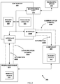
- FIG. 2 is a conceptual block diagram illustrating details of an example controller 220 and an example propulsor engine 210, in accordance with one or more techniques of this disclosure.
- Propulsor engine 210 and controller 220 may be configured to exchange information 240A via communication channel 230A and via interface 226A.
- System 200 may also include diagnostic device 250 configured to receive diagnostic information from controller 220 via maintenance port 228.
- System 200 also includes 260 configured to exchange information 240B with controller 220 via communication channel 230B and via interface 226B.
- Propulsor engine 210 may include a memory device 212, controller 220 may include a memory device 222, and component 260 may include memory device 262.
- Memory devices 212, 222, and 262 may be configured to store data relating to the performance of propulsor engine 210, such as temperatures, pressures, speeds, fuel flow rates, vibration, other "health" characteristics for prognostic purposes, and the like.
- Memory devices 212, 222, and 262 may also be configured to store an algorithm for determining a new frequency or a set list of frequencies to cycle through for each communication session.
- Memory device 222 may be configured to store a master set list for all devices in communication with controller 220 or a separate set list for each device that is in communication with controller 220.
- Propulsor engine 210 and/or component 260 may be configured to request a seed (e.g., a number) from controller 220 at the beginning of a communication session. Controller 220 may be configured to transmit a seed to propulsor engine 210 and/or component 260 in response to the request(s). Propulsor engine 210 and/or component 260 may be configured to input the seed into the algorithm to generate a new frequency for the exchange of information 240A and/or 240B.
- a seed e.g., a number
- Controller 220 may be configured to transmit a seed to propulsor engine 210 and/or component 260 in response to the request(s).
- Propulsor engine 210 and/or component 260 may be configured to input the seed into the algorithm to generate a new frequency for the exchange of information 240A and/or 240B.
- Propulsor engine 210 may be configured to exchange information 240A with controller 220 during a previous communication session.
- the previous communication session may end when controller 220 powers off propulsor engine 210.
- propulsor engine 210 may be configured to determine a frequency for a new communication session on communication channel 230A based on the frequency of the previous communication session and an algorithm.
- propulsor engine 210 may be configured to receive a seed number from controller 220 at the beginning of the new communication session at the previous frequency.
- Propulsor engine 210 may be configured to determine the new frequency based on the seed number and the algorithm, which may include a random or pseudorandom number generator. Propulsor engine 210 may be configured to exchange information 240A with controller 220 at the frequency for the new communication session via communication channel 230A and decode information 240A received from controller 220 based on the frequency for the new communication session. Component 260 may be configured to determine frequencies, exchange information 240B, and decode information 240B in a similar manner to propulsor engine 210.
- Interfaces 226A and 226B may include a pin, a lead, an optical port, and/or any other type of interface between controller 220 and communication channels 230A and 230B.
- Communication channels 230A and 230B may include a wired connection such as an optical fiber cable and/or a metal wire between propulsor engine 210 and controller 220.
- communication channels 230A and 230B may include a pad or trace on a printed circuit board (PCB), and interfaces 226A and 226B may include a pin that is configured to be soldered to the pad or trace.
- PCB printed circuit board
- interfaces 226A and 226B may include a laser, a light emitting diode (LED), a photodiode, a photoresistor, and/or photo-acceptance unit configured to convert between electrical signals and optical signals.
- interfaces 226A and 226B may include an antenna configured to transmit and/or receive wireless electromagnetic signals.
- Processing circuitry 224 may include integrated circuitry with digital logic or analog circuitry configured to determine a frequency for a new communication session on communication channel 230A or 230B based on a frequency of a previous communication session. Processing circuitry 224 may be configured to encode information 240A in the frequency for the current communication session over communication channel 230A. Processing circuitry 224 may also be configured to encode information 240B in the frequency for the current communication session over communication channel 230B. Processing circuitry 224 may be configured to determine new frequencies based on previous frequencies and an algorithm, a set list, a random number seed, and/or any other method of determining a new frequency. In some examples, processing circuitry 224 may be configured to determine a seed at the start of a new communication session and transmit the seed to the follower device (i.e., propulsor engine 210 or component 260.
- the follower device i.e., propulsor engine 210 or component 260.
- Diagnostic device 250 may be configured to receive diagnostic information from maintenance port 228 of controller 220 by at least transmitting a request for diagnostic information to controller 220.
- the diagnostic information may indicate the operations of propulsor engine 210 and controller 220.
- a maintenance worker may use diagnostic device 250 to troubleshoot issues with propulsor engine 210 and download data.
- the data may include communication faults, failure mode bits, and/or other status bits and status information regarding the operation of propulsor engine 210 and/or component 260.
- the maintenance worker may also use diagnostic device 250 to test the performance of propulsor engine 210 and/or controller 220.
- the request received by maintenance port 228 from diagnostic device 250 for diagnostic information may include a passcode, such as a four-digit number.
- An authorized maintenance worker may operate diagnostic device 250, or an attacker may operate diagnostic device 250 to snoop on or hack into controller 220.
- Controller 220 may be configured to receive the request for diagnostic information from diagnostic device 250, where the diagnostic information indicates the operations of propulsor engine 210. Controller 220 may be further configured to confirm that the passcode in the request matches a security code for controller 220 that may be stored in memory device 222. Controller 220 may be configured to transmit the requested diagnostic information through maintenance port 228 to diagnostic device 250 in response to confirming that the passcode matches the security code.
- An attacker may use diagnostic device to snoop on the operations of propulsor engine 210 and/or controller 220. If the attacker sends a request with an incorrect passcode from diagnostic device 250 to maintenance port 228, controller 220 may be configured to reject the request in response to determining that the passcode in the request does not match the security code. Controller 220 may be configured to set a bit indicating unauthorized access attempts in response to receiving a threshold number of consecutive requests with incorrect passcodes or a threshold number of requests in a threshold time duration.
- Component 260 may include a component that controls the operation of propulsor engine 210 (i.e., a controlling component), such as an actuator or a servo. Additionally or alternatively, component 260 may include a sensor or a data collection device, which may be referred to as "non-controlling components.” Component 260 may be positioned inside propulsor engine 210 (i.e., an internal component) and/or positioned outside propulsor engine 210 (i.e., an external component or auxiliary component).
- a sensor may be configured to sense various parameters of the operation of propulsor engine 210, such as a temperature, a pressure, a speed, a movement or a deflection, and/or any other parameters of system 200 and/or propulsor engine 210.
- Controller 220 may be configured to monitor the performance of propulsor engine 210 based on information 240B received from a sensor or data collection device.
- a data collection device may be configured to measure or track the performance of propulsor engine 210 by counting the times that the performance exceeds or fails to meet a threshold.
- a data collection device may include a camera configured to collect images of propulsor engine 210.
- An actuator may be configured to move a part of system 200 and/or propulsor engine 210, such as a piston, a transmission, a gearbox, valves such as air bleed valves, and/or any other part of system 200.
- an actuator of component 260 may be configured to change the geometry of propulsor engine 210 by moving the vanes of a compressor or a turbine of propulsor engine 210.
- An actuator of component 260 may be configured to change a nozzle exhaust area and/or control the flow of fuel by fluid servo valve actuation.
- Component 260 may communicate with controller 220 via communication channel 230B within a predetermined frequency band, where the predetermined frequency band is particular to each component 260 or to each component type. For example, if component 260 includes a sensor type component, controller 220 may be configured to determine a frequency for a new communication session to exchange information 240B with the sensor in a predetermined frequency band ranging from three hundred megahertz to four hundred megahertz. Whereas, if component 260 includes an actuator type component, controller 220 may be configured to determine a frequency for a new communication session to exchange information 240B with the actuator in a predetermined frequency band ranging from six megahertz to seven megahertz. Controller 220 may also be configured to determine the frequency for a communication session with propulsor engine 210 in a predetermined frequency band.
- Component 260 may be configured to determine a frequency for a new communication session on communication channel 230B based on a frequency of a previous communication session and an algorithm or set list stored to memory device 262.
- component 260 may be configured to scan a predetermined frequency band for control signals transmitted by controller 220 to component 260.
- component 260 may be configured to transmit an acknowledgement signal to controller 220.
- Controller 220 may be configured to set a bit in memory device 222 to indicate a failure mode in response to not receiving the acknowledgement signal from component 260.
- controller 220 may be configured to set a timer at the beginning of a communication session. If the timer expires before controller 220 receives an acknowledgement signal from component 260 or propulsor engine 210, controller 220 may be configured to set a bit in memory device 222 to indicate a failure mode for the respective device that failed to acknowledge communications.
- Component 260 may be configured to exchange information 240B with controller 220 at a first frequency during a previous communication session.
- Component 260 may be configured to determine a second frequency for a new communication session on communication channel 230B based on the first frequency and an algorithm and/or a set list stored to memory device 262.
- Component 260 may be configured to exchange information 240B with controller 220 at the second frequency via communication channel 230B and decode information 240B received from controller 220 based on the second frequency for the new communication session.
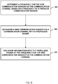
- FIG. 3 is a flowchart illustrating an example process implemented by a controller to control the operation of a propulsor engine, in accordance with one or more techniques of this disclosure. Operations 302-306 are described in the context of system 100 and controller 120 of FIG. 1 , although other controllers, such as controller 220 of FIG. 2 may perform similar operations.
- controller 120 determines a frequency for the new communication session on communication channel 130 based on a frequency of a previous communication session (300).
- the frequency for the new communication session may be different than the frequency of the previous communication session.
- controller 120 may be configured to determine the frequency for the new communication session based on the previous frequency and an algorithm or a set list.
- controller 120 may be configured to choose a seed and determine the new frequency based on the previous frequency and/or the previous seed.
- controller 120 may be configured to transmit the seed to propulsor engine 110 at the beginning of the new communication session using the previous seed.
- Propulsor engine 110 may be configured to independently determine the new frequency based on the seed and the algorithm, which may be stored to a memory device in propulsor engine 110.
- controller 120 establishes a new communication session via communication channel 130 with propulsor engine 110 (302).
- controller 120 may be configured to establish a new communication session when propulsor engine 110 powers on.
- controller 120 may be configured to power on propulsor engine 110 by controlling a starting device to initiate the operation of propulsor engine 110.
- Controller 120 may be configured to initiate the new communication session at a new frequency determined by controller 120.
- controller may be configured to transmit signals at the frequency of a previous communication session at the beginning of the new communication session before determining a new frequency. Controller 120 may also be configured to terminate or conclude the new communication session when propulsor engine 110 powers off.
- controller 120 exchanges information 140 with propulsor engine 110 at the frequency for the new communication session via communication channel 130 (306).
- Controller 120 may be configured to exchange information 140 by at least transmitting control signals to propulsor engine 110 to control the operations of propulsor engine 110.
- controller 120 may be configured to cause propulsor engine 110 to generate more or less propulsion, to increase or decrease rotational speed, power on, or power off.
- Controller 120 may be configured to receive information 140 such as fuel flow level(s), engine temperature(s), engine pressure(s), and maintenance information from propulsor engine 110.
- FIG. 3 has described the operation of controller 120 and system 100 in general.
- system 100 may include one or more components configured to sense various parameters of the operations of propulsor engine 110 and/or move a part of propulsor engine 110.
- Controller 120 may be configured to establish a new communication session with each component when propulsor engine 110 powers on.
- Controller 120 may be configured to determine a unique new frequency for each component based on a unique algorithm or unique set list of frequencies.
- the devices of system 100 may be configured to operate in a default communication state in case of a system failure.
- One or more non-responsive devices may result in a shutdown of system 100, unless controller 120 is able to establish a communication channel with the non-responsive device(s).
- Propulsor engine 110, controller 120, and/or any other device(s) may be configured to communicate using a backup frequency in the case of a communication failure.
- the backup frequency may be a default frequency for the particular non-responsive device or, alternatively, the last frequency at which controller 120 successfully communicated with the non-responsive device.
- controller 120 may be configured to determine a frequency for a future communication session on communication channel 130 and any other communication channels based on a frequency of a current communication session. Controller 120 may be configured to determine the frequency for the future communication session before propulsor engine 110 is powered off to end the current communication session. Controller 120 may be configured to communicate the frequency for the future communication session to the respective device before propulsor engine 110 is powered off. Each device may be configured to store the frequency for the future communication session and begin operating at the frequency for the future communication session when propulsor engine 110 powers on.
- FIG. 4 is a flowchart illustrating an example process implemented by a controller for communicating with a propulsor engine and/or one or more components of the propulsor engine, in accordance with one or more techniques of this disclosure.
- Operations 400-426 are described in the context of system 200 and controller 220 of FIG. 2 , although other controllers, such as controller 120 of FIG. 1 , may perform similar operations.
- controller 220 may power up system 200 including propulsor engine 210 (400). Controller 220 may be configured to transmit control signals to a starter device to power up propulsor engine 210. In the example of FIG. 4 , controller 220 may activate all communications in system 200 except external communications (402). Controller 220 may activate communications with propulsor engine 210 and component 260 by transmitting signals at the frequency of the previous communication session, which may have concluded the last time that propulsor engine 210 was powered down.
- controller 220 may assign a frequency to each communication type (404). For example, controller 220 may be configured to assign a first frequency for communication channel 230A based on a previous frequency for communication channel 230A and assign a second frequency for communication channel 230B based on a previous frequency for communication channel 230B. In the example of FIG. 4 , controller 220 may determine that all communication types have not been assigned a frequency (406) and continue to assign frequencies.
- controller 220 may validate that communication type functions properly with a seed request from each type of device or component (e.g., propulsor engine 210 and component 260) in system 200 (408). In some examples, controller 220 may receive seed requests from propulsor engine 210 and component 260 and may be configured to respond by transmitting seeds to propulsor engine 210 and component 260. Propulsor engine 210 and component 260 may use the seeds to determine a new frequency based on an algorithm stored to memory device 212 and 262.
- a seed request from each type of device or component (e.g., propulsor engine 210 and component 260) in system 200 (408). In some examples, controller 220 may receive seed requests from propulsor engine 210 and component 260 and may be configured to respond by transmitting seeds to propulsor engine 210 and component 260. Propulsor engine 210 and component 260 may use the seeds to determine a new frequency based on an algorithm stored to memory device 212 and 262.
- controller 220 may assign another frequency to communication channel 230A (410, 412, and 404). If controller 220 determines that communication channel 230B is not communicating and has been reassigned more than N times, controller 220 may set a communication fault for communication channel 230B (410, 412, and 416). In some examples, N may be any integer, such as three, serving as a threshold number of times to reassign the frequency for communication channel 230A.
- the communication fault may be a bit in a status register that controller 220 may be configured to transmit to diagnostic device 250 in response to a request for diagnostic information.
- controller 220 may attempt to communicate with propulsor engine 210 using a backup frequency (417).
- the backup frequency may be a default frequency for propulsor engine 210 or the last frequency at which controller 220 successfully communicated with propulsor engine 210.
- controller 220 may store a definition of the active communication channel (e.g., communication channel 230A) (410 and 414).
- the definition may include the established frequency for communication channel 230A.
- controller 220 may determine that system 200 is on the ground and, in response, activate maintenance port 228 (418 and 420). If system 200 includes a vehicle as such as aircraft, authorized personnel may perform maintenance on system 200 while on the ground. Controller 220 may determine that system 200 is not on the ground and, in response, configure system 200 for normal operation (418 and 422). In normal operation, propulsor engine 210 may be configured to generate propulsion for system 200, and component 260 may be configured to sense the operation of propulsor engine 210 or move a part of propulsor engine 210.
- controller 220 may determine that shutdown has not been requested and, in response, continue normal operation (424 and 422). If controller 220 determines that shutdown has been requested or if controller 220 has activated maintenance port 228, controller 220 may power down system 200 (424, 420, and 426). Controller 220 may be configured to power down system 200 by reducing the speed of propulsor engine 210 to zero and turning off component 260.
Landscapes
- Engineering & Computer Science (AREA)
- Computer Security & Cryptography (AREA)
- Computer Networks & Wireless Communication (AREA)
- Signal Processing (AREA)
- Computer Hardware Design (AREA)
- Computing Systems (AREA)
- General Engineering & Computer Science (AREA)
- Radar, Positioning & Navigation (AREA)
- Remote Sensing (AREA)
- Combined Controls Of Internal Combustion Engines (AREA)
Abstract
Description
- This disclosure relates to control systems for propulsor engines.
- A propulsor engine (e.g., of a vehicle system) may include a controller configured to control the operations of the propulsor engine, and in some cases, the operations of components, such as sensors, actuators, and data collection devices, associated with the propulsor engine. The controller may communicate with the propulsor engine and the components by transmitting control signals on an open, unsecure communication channel. If an attacker or other such unauthorized user knows the frequency of the communication channel, the attacker may be able to snoop on or even interfere with the control signals being sent via the communication channel thereby potentially impacting the operations of the propulsor engine and the components of the propulsor engine.
- In a first aspect there is provided a system comprising: a propulsor engine; and a controller configured to: determine a frequency for a new communication session on a communication channel based on a frequency of a previous communication session, wherein the frequency for the new communication session is different than the frequency of the previous communication session; establish the new communication session via the communication channel with the propulsor engine; and exchange information with the propulsor engine at the frequency for the new communication session via the communication channel.
- The controller may be further configured to: exchange information with the propulsor engine during the previous communication session via the communication channel; power off the propulsor engine after exchanging information with the propulsor engine during the previous communication session; and power on the propulsor engine after powering off the propulsor engine, wherein the controller may be configured to exchange information with the propulsor engine at the frequency for the new communication session via the communication channel after powering on the propulsor engine and after determining the frequency for the new communication session.
- The controller may be configured to determine the frequency for the new communication session based on an algorithm that may include: determining a seed for the new communication session based on a seed for the previous communication session; applying the seed for the new communication session to a random number generator or a pseudorandom number generator to generate a number for the new communication session based on the seed for the new communication session; and determining the frequency for the new communication session by scaling the number for the new communication session to a number between a minimum frequency and a maximum frequency of a predetermined frequency band.
- The propulsor engine may be configured to: exchange information with the controller during the previous communication session; determine a frequency for the new communication session on the communication channel based on the frequency of the previous communication session and the algorithm; exchange information with the controller at the frequency for the new communication session via the communication channel; and decode information received from the controller based on the frequency for the new communication session.
- The propulsor engine may be configured to transmit an acknowledgement signal to the controller in response to receiving information from the controller, and wherein the controller may be further configured to set a bit indicating a failure mode in response to not receiving the acknowledgement signal from the propulsor engine.
- The controller may be configured to: determine the frequency for the new communication session within a predetermined frequency band; and transmit control signals to the propulsor engine at the frequency for the new communication session via the communication channel, wherein the propulsor engine may be further configured to scan the predetermined frequency band for control signals transmitted by the controller to the propulsor engine.
- The communication channel may comprise a cable including an optical fiber cable or a metal wire, wherein the controller may be configured to exchange information with the propulsor engine at the frequency for the new communication session via the cable.
- The controller may be configured to exchange information with the propulsor engine using a communication protocol.
- The new communication session may be a first new communication session, the previous communication session may be a first previous communication session, the communication channel may be a first communication channel, the system may further comprise a component, and the controller may be further configured to: determine a frequency for a second new communication session on a second communication channel based on a frequency of a second previous communication session, wherein the frequency for the second new communication session may be different than the frequency of the second previous communication session; establish the second new communication session via the second communication channel with the component; and exchange information with the component at the frequency for the second new communication session via the second communication channel.
- The controller may be configured to determine the frequency for the first new communication session within a first frequency band, wherein the controller may be configured to determine the frequency for the second new communication session within a second frequency band, the first frequency band and the second frequency band may be different, and the second frequency band may be particular to a type of the component.
- The component may include a sensor configured to sense the operation of the propulsor engine, and the controller may be configured to determine the frequency for the second new communication session within a frequency band ranging from three hundred megahertz to four hundred megahertz.
- The component may include an actuator configured to move a part of the propulsor engine, and the controller may be configured to determine the frequency for the second new communication session within a frequency band ranging from six megahertz to seven megahertz.
- The controller may be configured to determine the frequency for the new communication session based on an algorithm and a seed number, the controller may be further configured to transmit the seed number to the propulsor engine at the frequency of the previous communication session, and the propulsor engine may be configured to determine the frequency for the new communication session based on the algorithm and the seed number.
- The system may further comprise a diagnostic device configured to receive diagnostic information from a maintenance port of the controller, wherein the controller may be configured to: receive a request for diagnostic information from the diagnostic device, wherein the request includes a passcode; confirm that the passcode matches a security code for the controller; and transmit the diagnostic information through the maintenance port to the diagnostic device in response to confirming that the passcode matches the security code, wherein the diagnostic information indicates operation of the propulsor engine.
- The system may comprise: a propulsor engine; a component; and a controller configured to: exchange information with the propulsor engine during a first previous communication session via a first communication channel; exchange information with the component during a second previous communication session via a second communication channel; power off the propulsor engine after exchanging information with the propulsor engine during the first previous communication session and after exchanging information with the component during the second previous communication session; power on the propulsor engine after powering off the propulsor engine; determine a frequency for the first new communication session on the first communication channel based on a frequency of a first previous communication session, wherein the frequency for the first new communication session is different than the frequency of the first previous communication session; determine a frequency for the second new communication session on the second communication channel based on a frequency of a second previous communication session, wherein the frequency for the second new communication session is different than the frequency of the second previous communication session; exchange information with the propulsor engine at the frequency for the first new communication session via the first communication channel; and exchange information with the component at the frequency for the second new communication session via the second communication channel.
- The controller may be configured to: determine the frequency for the first new communication session within a predetermined frequency band; and transmit control signals to the propulsor engine at the frequency for the first new communication session via the first communication channel, wherein the propulsor engine may be further configured to scan the predetermined frequency band for control signals transmitted by the controller to the propulsor engine.
- In a second aspect there is provided a method comprising: determining a frequency for a new communication session on a communication channel based on a frequency of a previous communication session, wherein the frequency for the new communication session is different than the frequency of the previous communication session; establishing the new communication session via the communication channel with a propulsor engine; and exchanging information with the propulsor engine at the frequency for the new communication session via the communication channel.
- The method may further comprise: exchanging information with the propulsor engine during the previous communication session via the communication channel; powering off the propulsor engine after exchanging information with the propulsor engine during the previous communication session; and powering on the propulsor engine after powering off the propulsor engine, wherein exchanging information with the propulsor engine at the frequency for the new communication session may comprise exchanging information with the propulsor engine at the frequency for the new communication session after powering on the propulsor engine and after determining the frequency for the new communication session.
- The method may further comprise: transmitting information to the propulsor engine at the frequency for the new communication session via the communication channel; not receiving an acknowledgement signal from the propulsor engine after transmitting information to the propulsor engine at the frequency for the new communication session; and setting a bit indicating failure mode in response to not receiving the acknowledgement signal from the propulsor engine.
- The new communication session may be a first new communication session, the communication channel may be the first communication channel, the previous communication session may be a first previous communication session, and the method may further comprise: determining a frequency for a second new communication session on a second communication channel based on a frequency of a second previous communication session, wherein the frequency for the second new communication session is different than the frequency of the second previous communication session; establishing the second new communication session via the second communication channel with a component; and exchanging information with the component at the frequency for the second new communication session via the second communication channel.
- The skilled person will appreciate that except where mutually exclusive, a feature or parameter described in relation to any one of the above aspects may be applied to any other aspect. Furthermore, except where mutually exclusive, any feature or parameter described herein may be applied to any aspect and/or combined with any other feature or parameter described herein..
- In some examples, the disclosure describes a system includes a propulsor engine and a controller configured to determine a frequency for a new communication session on a communication channel based on a frequency of a previous communication session, wherein the frequency for the new communication session is different than the frequency of the previous communication session. The controller is further configured to establish the new communication session via the communication channel with the propulsor engine. The controller is also configured to exchange information with the propulsor engine at the frequency for the new communication session via the communication channel.
- In some examples, the disclosure describes a method including determining a frequency for a new communication session on a communication channel based on a frequency of a previous communication session, wherein the frequency for the new communication session is different than the frequency of the previous communication session. The method further includes establishing the new communication session via the communication channel with a propulsor engine. The method also includes exchanging information with the propulsor engine at the frequency for the new communication session via the communication channel.
- In some examples, the disclosure describes a system including a propulsor engine, a component, and a controller configured to exchange information with the propulsor engine during a first previous communication session via a first communication channel. The controller is further configured to exchange information with the component during a second previous communication session via a second communication channel. The controller is also configured to power off the propulsor engine after exchanging information with the propulsor engine during the first previous communication session and after exchanging information with the component during the second previous communication session. The controller is configured to power on the propulsor engine after powering off the propulsor engine and determine a frequency for the first new communication session on the first communication channel based on a frequency of a first previous communication session, wherein the frequency for the first new communication session is different than the frequency of the first previous communication session. The controller is further configured to determine a frequency for the second new communication session on the second communication channel based on a frequency of a second previous communication session, wherein the frequency for the second new communication session is different than the frequency of the second previous communication session. The controller is also configured to exchange information with the propulsor engine at the frequency for the first new communication session via the first communication channel and exchange information with the component at the frequency for the second new communication session via the second communication channel.
- The details of one or more examples are set forth in the accompanying drawings and the description below. Other features, objects, and advantages will be apparent from the description and drawings, and from the claims.
- Embodiments will now be described by way of example only, with reference to the Figures, in which:
-
FIG. 1 is a conceptual block diagram illustrating a controller configured to control operations of a propulsor engine, in accordance with one or more techniques of this disclosure. -
FIG. 2 is a conceptual block diagram illustrating details of an example controller and an example propulsor engine, in accordance with one or more techniques of this disclosure. -
FIG. 3 is a flowchart illustrating an example process implemented by a controller to control the operations of a propulsor engine, in accordance with one or more techniques of this disclosure. -
FIG. 4 is a flowchart illustrating an example process implemented by a controller for communicating with a propulsor engine and/or one or more components of the propulsor engine, in accordance with one or more techniques of this disclosure. - In general, this disclosure describes techniques for establishing secure communication channels between a controller of a propulsor engine and components of the propulsor engine (including internal and external or auxiliary components of the propulsor engine) by changing the frequency that is used for each communication session between the controller and the components of the propulsor engine (e.g., each time the propulsor engine is powered-on, or at other suitable times). The controller and the components of the propulsor engine may be configured to exchange information via a communication channel, such as a wired connection and/or a wireless connection. The controller may be configured to determine the frequency for a new communication session that is different from, but based on, the frequency used for a previous communication session.
- In this way, if an attacker or other such unauthorized user knows the frequency of a previous communication session, the techniques of this disclosure may enable the controller to prevent the attacker from snooping on or interfering with a new or current communication session. In other words, the attacker may be unable to snoop on or interfere with the information being exchanged between the controller and the propulsor engine because the controller will have changed the frequency for the current communication session so that the frequency is based on, but different than the frequency of the previous communication session.
-
FIG. 1 is a conceptual block diagram illustrating acontroller 120 configured to control operations of apropulsor engine 110, in accordance with one or more techniques of this disclosure. In some examples,system 100 may include additional propulsor engines additional controllers, and/or one or more components of the propulsor engines. In some examples, a single controller (e.g., controller 120) may be configured to control operations of multiple propulsor engines and multiple components, orsystem 100 may include more than one controller. The propulsion created bypropulsor engine 110 may be used in a variety of ways or for a variety of systems and applications (e.g., aircraft, locomotives, marine craft, power plants, electric generators, and any or all other systems and applications that rely on mechanical energy from a propulsor engine to perform work). -
Propulsor engine 110 may be configured to generate propulsion by converting fuel or electrical power to mechanical power.Propulsor engine 110 may be configured to periodically power on to generate propulsion and power off between operations. In some examples,propulsor engine 110 may include one or more internal components, such as an interface for exchanging information withcontroller 120, a memory device configured to store information exchanged withcontroller 120, and/or other components that are not shown inFIG. 1 . In some examples,propulsor engine 110 may include a turbine, a shaft, a compressor, a combustor, a generator, and/or any other internal components for generating propulsion and/or electricity.Propulsor engine 110 may be a gas turbine engine, a nuclear turbine engine, a steam turbine engine, internal combustion engine, Wankel engine, diesel engine, rotary engine, and/or any other suitable propulsor engine. - In some examples,
system 100 is a vehicle, andpropulsor engine 110 andcontroller 120 may be mounted on or within the vehicle. For example,propulsor engine 110 may include a turbine engine mounted as a center engine on an aircraft, a marine vehicle, or a tank. In some examples,propulsor engine 110 may include a turbine engine mounted on a wing of an aircraft or a marine vehicle. If the vehicle includes more than one propulsor engine,controller 120 may be a central controller configured to control the operations of all of the propulsor engines mounted on the vehicle, orcontroller 120 may be configured to control the operations ofonly propulsor engine 110. -
Controller 120 may be configured to determine a frequency for the new communication session throughcommunication channel 130 based on a frequency of a previous communication session. For example,controller 120 may be configured to determine the frequency for the new communication session based on an algorithm. In some examples,controller 120 may be configured to choose a seed to input in the algorithm.Controller 120 may be configured to transmit the chosen seed topropulsor engine 110 at the beginning of the new communication session, andpropulsor engine 110 may be configured to determine the new frequency based on the seed and the algorithm. -
Controller 120 may be configured to establish a communication session viacommunication channel 130 with components ofpropulsor engine 110. In some examples,controller 120 may be configured to establish a new communication session whenpropulsor engine 110 powers on. In some examples,controller 120 may be configured to power onpropulsor engine 110 by controlling a starting device to initiate the operation ofpropulsor engine 110.Controller 120 may be configured to initiate the new communication session at a new frequency determined bycontroller 120. In some examples, controller may be configured to initiate the new communication session at the frequency of a previous communication session beforecontroller 120 determines a new frequency.Controller 120 may also be configured to terminate or conclude the communication session whenpropulsor engine 110 powers off. - In some examples,
controller 120 may be configured to cycle through a set list of frequencies that is stored to a memory device.Controller 120 may be configured to iterate through the set list for each communication session. For example, an entry on the set list for the frequency for the new communication session may immediately follow the entry for the frequency of the previous communication session. In some examples,propulsor engine 110 may be configured to store the algorithm and/or set list so thatpropulsor engine 110 may decode the information transmitted bycontroller 120 topropulsor engine 110. -
Controller 120 may be configured to exchange information withpropulsor engine 110 at the frequency for the new communication session viacommunication channel 130.Controller 120 may be configured to exchangeinformation 140 by at least transmitting control signals topropulsor engine 110 to control the operations ofpropulsor engine 110. For example,controller 120 may be configured to causepropulsor engine 110 to generate more or less propulsion, to increase or decrease rotational speed, power on, or power off.Controller 120 may be configured to control the operation ofpropulsor engine 110 by controlling the operation of components ofpropulsor engine 110, such as actuators, starter devices, servos, and so on.Controller 120 may be configured to receiveinformation 140 such as fuel flow level(s), engine temperature(s), engine pressure(s), and maintenance information frompropulsor engine 110.Controller 120 may be configured to receiveinformation 140 from components such as sensors, data collection devices, and so on. - In some examples,
propulsor engine 110 andcontroller 120 may exchangeinformation 140 at a frequency during a previous communication session viacommunication channel 130.Controller 120 may be configured to conclude the previous communication session by powering offpropulsor engine 110 after exchanginginformation 140 during the previous communication session.Controller 120 may be configured to power offpropulsor engine 110 by transmitting control signals topropulsor engine 110 and/or actuators inpropulsor engine 110 to cause the speed ofpropulsor engine 110 to reduce to zero. After powering offpropulsor engine 110,controller 120 may be configured to power onpropulsor engine 110 and establish a new communication session viacommunication channel 130.Controller 120 may be configured to determine a frequency for the new communication session andexchange information 140 at the new frequency during the new communication session after powering offpropulsor engine 110. -
Controller 120 may include any suitable arrangement of hardware, software, firmware, or any combination thereof, to perform the techniques attributed tocontroller 120 herein. Examples ofcontroller 120 include any one or more microprocessors, digital signal processors (DSPs), application specific integrated circuits (ASICs), full authority digital engine control (FADEC) units, engine control units (ECUs), field programmable gate arrays (FPGAs), and/or any other equivalent integrated or discrete logic circuitry, as well as any combinations of such components. Whencontroller 120 includes software or firmware,controller 120 further includes any necessary hardware for storing and executing the software or firmware, such as one or more processors or processing units. In some examples,controller 120 may be integrated with the control unit forpropulsor engine 110, which may include a FADEC unit. - In general, a processing unit may include one or more microprocessors, DSPs, ASICs, FPGAs, or any other equivalent integrated or discrete logic circuitry, as well as any combinations of such components. Although not shown in
FIG. 1 ,controller 120 may include a memory device configured to store data. The memory device may include any volatile or non-volatile media, such as a random access memory (RAM), read only memory (ROM), non-volatile RAM (NVRAM), electrically erasable programmable ROM (EEPROM), flash memory, and the like. In some examples, the memory device may be external to controller 120 (e.g., may be external to a package in whichcontroller 120 is housed). -
Communication channel 130 may include a wired connection such as an optical fiber cable and/or a metal wire betweenpropulsor engine 110 andcontroller 120. In some examples,communication channel 130 may include a controller area network (CAN) bus, an ethernet cord, coaxial cables, digital subscriber line (DSL), and/or any other physical connection.Communication channel 130 may include an optical fiber cable made of silicon, fluoride glass, phosphate glass, chalcogenide glass, and/or sapphire, a copper wire, an aluminum wire, a nickel wire, a steel wire, and/or any other material configured to conduct signals or transferinformation 140. - Additionally or alternatively,
communication channel 130 may include a wireless connection, such as Bluetooth, infrared, radio frequency (RF), and/or microwave signals, across a medium such as air.Propulsor engine 110 andcontroller 120 may be configured to establish a wireless connection acrosscommunication channel 130 during each communication session by transmitting and receiving wireless signals. Whenpropulsor engine 110 and/orcontroller 120 are powered off, a wireless component ofcommunication channel 130 may cease to exist untilpropulsor engine 110 and/orcontroller 120 are powered on again. - In some examples, a wireless connection between
propulsor engine 110 andcontroller 120 may be susceptible to snooping and/or frequency jamming by nearby devices and systems. An attacker may intentionally or unintentionally interfere with the wireless signals acrosscommunication channel 130 in order to disrupt the flow ofinformation 140.System 100 may be especially vulnerable to interference ifsystem 100 is mounted on a vehicle such as an aircraft. The aircraft may travel through areas with varying degrees of electromagnetic interference and noise. Moreover, attackers may specifically target aircraft, especially military aircraft and commercial airliners, to intentionally jam or snoop on wireless communications betweenpropulsor engine 110 andcontroller 120. -
Information 140 may include data encoded in electromagnetic signals and/or optical signals conducted over an optical fiber, a metal wire, and/or a wireless medium such as air. The electromagnetic signals and/or optical signals may encodeinformation 140 using amplitude modulation, frequency modulation, a form of digital modulation, and/or another form of encoding.Information 140 may include control signals transmitted bycontroller 120 topropulsor engine 110 to control the operations ofpropulsor engine 110.Information 140 may include data indicating the status ofpropulsor engine 110 transmitted frompropulsor engine 110 tocontroller 120. -
Propulsor engine 110 andcontroller 120 may be configured to exchangeinformation 140 overcommunication channel 130 using a protocol or encoding, such as Aeronautical Radio, Incorporated (ARINC) standard 429 or ARINC standard 629, time-triggered ethernet, a CAN protocol, and/or any other suitable protocol.Propulsor engine 110 andcontroller 120 may be configured to encodeinformation 140 based on the protocol into a bit stream or an analog signal and transmit the signal acrosscommunication channel 130.Propulsor engine 110 andcontroller 120 may also be configured to decodeinformation 140 received fromcommunication channel 130 based on the protocol. In some examples,information 140 may use a digital protocol (e.g., shift-keying) or an analog protocol (e.g., modulation) to encodeinformation 140 in electromagnetic signals and/or optical signals. - In accordance with the techniques of this disclosure,
controller 120 may be configured to determine a frequency for a new communication session based on the frequency during a previous communication session. The new frequency may be different than the previous frequency in order to impede snooping, interference, and/or jamming. For example,controller 120 may use an algorithm and/or a random number seed to determine a new frequency, orcontroller 120 may read a set list of frequencies that is stored to a memory device. In order to establishcommunication channel 130, each ofpropulsor engine 110 andcontroller 120 may be configured to determine the new frequency before exchanginginformation 140 during the new communication session. For example,propulsor engine 110 andcontroller 120 may be configured to synchronize the frequencies of their transmissions before exchanginginformation 140 during the new communication session. In some examples,propulsor engine 110 and/orcontroller 120 may be configured to scan a predetermined frequency band oncommunication channel 130 for signals transmitted bypropulsor engine 110 orcontroller 120. -
Controller 120 andpropulsor engine 110 may use frequency-hopping and/or rolling-code technology to prevent an attacker from observing the exchange ofinformation 140 during a first communication session and snooping on the exchange ofinformation 140 during a later communication session. After the end of a first communication session,controller 120 andpropulsor engine 110 may be configured to use the same original seed and the same algorithm, which may include a number generator, to determine a new frequency.Controller 120 andpropulsor engine 110 may also be configured to determine more than one frequency in the future in case the other device (e.g.,controller 120 or propulsor engine 110) skips a frequency in the algorithm or set list. - As an example,
controller 120 may use a seed equal to a value of one to determine a frequency for a first communication session withpropulsor engine 110.Controller 120 may share the seed withpropulsor engine 110, and bothpropulsor engine 110 andcontroller 120 may apply the seed to a pseudorandom number generator and use the generated number to determine a frequency. Equation (1) is one possible equation for determining a frequency based on a pseudo-randomly, or randomly, generated number N between zero and one, wherein fmax and fmin are the maximum and minimum frequencies of a frequency band. In some examples,controller 120 may be configured to store a set list, where the entries of the set list are values of N forcontroller 120 to use for communication sessions. Each component ofsystem 100, or each component type of system, may have a predetermined frequency band with a maximum frequency and a minimum frequency. Equation (1) scales or stretches the generated number N, which may have a value between zero and one, to a frequency between the maximum frequency and a minimum frequency.
- During the next communication session,
controller 120 may be configured to increment the seed to a value of two.Controller 120 may then be configured to apply the new seed to the pseudorandom number generator and use the generated number and Equation (1) to determine a new frequency. In some examples,controller 120 may be configured to determine a new seed based on a method other than incrementing the previous seed. For example,controller 120 may be configured to use Equation (2) to generate a new seed (ki) based on a previous seed (ki-1). C is a constant that may be equal to two, three, or any other integer.
- If the new seed is greater than a threshold,
controller 120 may be configured to reset the value of the new seed to a predetermined value, such as one, before applying the new seed to the pseudorandom number generator.Controller 120 may also be configured to transmit the new seed topropulsor engine 110 at the beginning of a new communication session using the frequency of the previous communication session.Propulsor engine 110 may be configured to determine the new frequency based on the new seed received fromcontroller 120 and an algorithm that includes the pseudorandom generator and Equation (1). For the remainder of the new communication session,propulsor engine 110 andcontroller 120 may exchange information at the new frequency. Table I shows seeds, generated numbers, and frequencies for four communication sessions based on a minimum frequency of four hundred megahertz, a maximum frequency of five hundred megahertz, and C equals three.Table I. Four example communication sessions. Session k N f(MHz) 1 1 0.6818 468.18 2 2 0.4186 441.86 3 5 0.3381 433.81 4 14 0.9248 492.48 - In some examples,
controller 120 may be configured to transmit, at the beginning of a new communication session, control signals topropulsor engine 110 at the frequency of a previous communication session.Propulsor engine 110 may be configured to respond to the control signals by transmitting an acknowledgement signal tocontroller 120.Propulsor engine 110 andcontroller 120 may then be configured to begin exchanginginformation 140 during the new communication session at a new frequency based on an algorithm or an established list of frequencies. Ifcontroller 120 does not receive an acknowledgement signal frompropulsor engine 110, which may occur ifpropulsor engine 110 transmit an acknowledgement signal at a different frequency, thencontroller 120 may be configured to set a bit indicating a failure mode.Controller 120 may be configured to set the bit in a status register and report the bit to a diagnostic device through a maintenance port, as explained in further detail below. -
FIG. 2 is a conceptual block diagram illustrating details of anexample controller 220 and anexample propulsor engine 210, in accordance with one or more techniques of this disclosure.Propulsor engine 210 andcontroller 220 may be configured to exchangeinformation 240A viacommunication channel 230A and viainterface 226A.System 200 may also includediagnostic device 250 configured to receive diagnostic information fromcontroller 220 viamaintenance port 228.System 200 also includes 260 configured to exchangeinformation 240B withcontroller 220 viacommunication channel 230B and viainterface 226B. -
Propulsor engine 210 may include amemory device 212,controller 220 may include amemory device 222, andcomponent 260 may includememory device 262.Memory devices propulsor engine 210, such as temperatures, pressures, speeds, fuel flow rates, vibration, other "health" characteristics for prognostic purposes, and the like.Memory devices Memory device 222 may be configured to store a master set list for all devices in communication withcontroller 220 or a separate set list for each device that is in communication withcontroller 220. -
Propulsor engine 210 and/orcomponent 260 may be configured to request a seed (e.g., a number) fromcontroller 220 at the beginning of a communication session.Controller 220 may be configured to transmit a seed topropulsor engine 210 and/orcomponent 260 in response to the request(s).Propulsor engine 210 and/orcomponent 260 may be configured to input the seed into the algorithm to generate a new frequency for the exchange ofinformation 240A and/or 240B. -
Propulsor engine 210 may be configured to exchangeinformation 240A withcontroller 220 during a previous communication session. The previous communication session may end whencontroller 220 powers offpropulsor engine 210. Aftercontroller 220 subsequently powers onpropulsor engine 210 after powering offpropulsor engine 210,propulsor engine 210 may be configured to determine a frequency for a new communication session oncommunication channel 230A based on the frequency of the previous communication session and an algorithm. In some examples,propulsor engine 210 may be configured to receive a seed number fromcontroller 220 at the beginning of the new communication session at the previous frequency. -
Propulsor engine 210 may be configured to determine the new frequency based on the seed number and the algorithm, which may include a random or pseudorandom number generator.Propulsor engine 210 may be configured to exchangeinformation 240A withcontroller 220 at the frequency for the new communication session viacommunication channel 230A and decodeinformation 240A received fromcontroller 220 based on the frequency for the new communication session.Component 260 may be configured to determine frequencies,exchange information 240B, and decodeinformation 240B in a similar manner topropulsor engine 210. -
Interfaces controller 220 andcommunication channels Communication channels propulsor engine 210 andcontroller 220. In some examples,communication channels interfaces interfaces interfaces -
Processing circuitry 224 may include integrated circuitry with digital logic or analog circuitry configured to determine a frequency for a new communication session oncommunication channel Processing circuitry 224 may be configured to encodeinformation 240A in the frequency for the current communication session overcommunication channel 230A.Processing circuitry 224 may also be configured to encodeinformation 240B in the frequency for the current communication session overcommunication channel 230B.Processing circuitry 224 may be configured to determine new frequencies based on previous frequencies and an algorithm, a set list, a random number seed, and/or any other method of determining a new frequency. In some examples,processing circuitry 224 may be configured to determine a seed at the start of a new communication session and transmit the seed to the follower device (i.e.,propulsor engine 210 orcomponent 260. -
Diagnostic device 250 may be configured to receive diagnostic information frommaintenance port 228 ofcontroller 220 by at least transmitting a request for diagnostic information tocontroller 220. The diagnostic information may indicate the operations ofpropulsor engine 210 andcontroller 220. A maintenance worker may usediagnostic device 250 to troubleshoot issues withpropulsor engine 210 and download data. The data may include communication faults, failure mode bits, and/or other status bits and status information regarding the operation ofpropulsor engine 210 and/orcomponent 260. The maintenance worker may also usediagnostic device 250 to test the performance ofpropulsor engine 210 and/orcontroller 220. - The request received by
maintenance port 228 fromdiagnostic device 250 for diagnostic information may include a passcode, such as a four-digit number. An authorized maintenance worker may operatediagnostic device 250, or an attacker may operatediagnostic device 250 to snoop on or hack intocontroller 220.Controller 220 may be configured to receive the request for diagnostic information fromdiagnostic device 250, where the diagnostic information indicates the operations ofpropulsor engine 210.Controller 220 may be further configured to confirm that the passcode in the request matches a security code forcontroller 220 that may be stored inmemory device 222.Controller 220 may be configured to transmit the requested diagnostic information throughmaintenance port 228 todiagnostic device 250 in response to confirming that the passcode matches the security code. - An attacker may use diagnostic device to snoop on the operations of
propulsor engine 210 and/orcontroller 220. If the attacker sends a request with an incorrect passcode fromdiagnostic device 250 tomaintenance port 228,controller 220 may be configured to reject the request in response to determining that the passcode in the request does not match the security code.Controller 220 may be configured to set a bit indicating unauthorized access attempts in response to receiving a threshold number of consecutive requests with incorrect passcodes or a threshold number of requests in a threshold time duration. -
Component 260 may include a component that controls the operation of propulsor engine 210 (i.e., a controlling component), such as an actuator or a servo. Additionally or alternatively,component 260 may include a sensor or a data collection device, which may be referred to as "non-controlling components."Component 260 may be positioned inside propulsor engine 210 (i.e., an internal component) and/or positioned outside propulsor engine 210 (i.e., an external component or auxiliary component). A sensor may be configured to sense various parameters of the operation ofpropulsor engine 210, such as a temperature, a pressure, a speed, a movement or a deflection, and/or any other parameters ofsystem 200 and/orpropulsor engine 210.Controller 220 may be configured to monitor the performance ofpropulsor engine 210 based oninformation 240B received from a sensor or data collection device. A data collection device may be configured to measure or track the performance ofpropulsor engine 210 by counting the times that the performance exceeds or fails to meet a threshold. A data collection device may include a camera configured to collect images ofpropulsor engine 210. - An actuator may be configured to move a part of
system 200 and/orpropulsor engine 210, such as a piston, a transmission, a gearbox, valves such as air bleed valves, and/or any other part ofsystem 200. In some examples, an actuator ofcomponent 260 may be configured to change the geometry ofpropulsor engine 210 by moving the vanes of a compressor or a turbine ofpropulsor engine 210. An actuator ofcomponent 260 may be configured to change a nozzle exhaust area and/or control the flow of fuel by fluid servo valve actuation. -
Component 260 may communicate withcontroller 220 viacommunication channel 230B within a predetermined frequency band, where the predetermined frequency band is particular to eachcomponent 260 or to each component type. For example, ifcomponent 260 includes a sensor type component,controller 220 may be configured to determine a frequency for a new communication session to exchangeinformation 240B with the sensor in a predetermined frequency band ranging from three hundred megahertz to four hundred megahertz. Whereas, ifcomponent 260 includes an actuator type component,controller 220 may be configured to determine a frequency for a new communication session to exchangeinformation 240B with the actuator in a predetermined frequency band ranging from six megahertz to seven megahertz.Controller 220 may also be configured to determine the frequency for a communication session withpropulsor engine 210 in a predetermined frequency band. -
Component 260 may be configured to determine a frequency for a new communication session oncommunication channel 230B based on a frequency of a previous communication session and an algorithm or set list stored tomemory device 262. In some examples,component 260 may be configured to scan a predetermined frequency band for control signals transmitted bycontroller 220 tocomponent 260. In response tocomponent 260 receivinginformation 240B fromcontroller 220 at the beginning of a communication session,component 260 may be configured to transmit an acknowledgement signal tocontroller 220.Controller 220 may be configured to set a bit inmemory device 222 to indicate a failure mode in response to not receiving the acknowledgement signal fromcomponent 260. In some examples,controller 220 may be configured to set a timer at the beginning of a communication session. If the timer expires beforecontroller 220 receives an acknowledgement signal fromcomponent 260 orpropulsor engine 210,controller 220 may be configured to set a bit inmemory device 222 to indicate a failure mode for the respective device that failed to acknowledge communications. -
Component 260 may be configured to exchangeinformation 240B withcontroller 220 at a first frequency during a previous communication session.Component 260 may be configured to determine a second frequency for a new communication session oncommunication channel 230B based on the first frequency and an algorithm and/or a set list stored tomemory device 262.Component 260 may be configured to exchangeinformation 240B withcontroller 220 at the second frequency viacommunication channel 230B and decodeinformation 240B received fromcontroller 220 based on the second frequency for the new communication session. -
FIG. 3 is a flowchart illustrating an example process implemented by a controller to control the operation of a propulsor engine, in accordance with one or more techniques of this disclosure. Operations 302-306 are described in the context ofsystem 100 andcontroller 120 ofFIG. 1 , although other controllers, such ascontroller 220 ofFIG. 2 may perform similar operations. - In the example of
FIG. 3 ,controller 120 determines a frequency for the new communication session oncommunication channel 130 based on a frequency of a previous communication session (300). The frequency for the new communication session may be different than the frequency of the previous communication session. For example,controller 120 may be configured to determine the frequency for the new communication session based on the previous frequency and an algorithm or a set list. In some examples,controller 120 may be configured to choose a seed and determine the new frequency based on the previous frequency and/or the previous seed. In some examples,controller 120 may be configured to transmit the seed topropulsor engine 110 at the beginning of the new communication session using the previous seed.Propulsor engine 110 may be configured to independently determine the new frequency based on the seed and the algorithm, which may be stored to a memory device inpropulsor engine 110. - In the example of
FIG. 3 ,controller 120 establishes a new communication session viacommunication channel 130 with propulsor engine 110 (302). In some examples,controller 120 may be configured to establish a new communication session whenpropulsor engine 110 powers on. In some examples,controller 120 may be configured to power onpropulsor engine 110 by controlling a starting device to initiate the operation ofpropulsor engine 110.Controller 120 may be configured to initiate the new communication session at a new frequency determined bycontroller 120. In some examples, controller may be configured to transmit signals at the frequency of a previous communication session at the beginning of the new communication session before determining a new frequency.Controller 120 may also be configured to terminate or conclude the new communication session whenpropulsor engine 110 powers off. - In the example of
FIG. 3 ,controller 120exchanges information 140 withpropulsor engine 110 at the frequency for the new communication session via communication channel 130 (306).Controller 120 may be configured to exchangeinformation 140 by at least transmitting control signals topropulsor engine 110 to control the operations ofpropulsor engine 110. For example,controller 120 may be configured to causepropulsor engine 110 to generate more or less propulsion, to increase or decrease rotational speed, power on, or power off.Controller 120 may be configured to receiveinformation 140 such as fuel flow level(s), engine temperature(s), engine pressure(s), and maintenance information frompropulsor engine 110. -
FIG. 3 has described the operation ofcontroller 120 andsystem 100 in general. In some examples,system 100 may include one or more components configured to sense various parameters of the operations ofpropulsor engine 110 and/or move a part ofpropulsor engine 110.Controller 120 may be configured to establish a new communication session with each component whenpropulsor engine 110 powers on.Controller 120 may be configured to determine a unique new frequency for each component based on a unique algorithm or unique set list of frequencies. - In some examples, the devices of
system 100 may be configured to operate in a default communication state in case of a system failure. One or more non-responsive devices may result in a shutdown ofsystem 100, unlesscontroller 120 is able to establish a communication channel with the non-responsive device(s).Propulsor engine 110,controller 120, and/or any other device(s) may be configured to communicate using a backup frequency in the case of a communication failure. The backup frequency may be a default frequency for the particular non-responsive device or, alternatively, the last frequency at whichcontroller 120 successfully communicated with the non-responsive device. - In some examples,
controller 120 may be configured to determine a frequency for a future communication session oncommunication channel 130 and any other communication channels based on a frequency of a current communication session.Controller 120 may be configured to determine the frequency for the future communication session beforepropulsor engine 110 is powered off to end the current communication session.Controller 120 may be configured to communicate the frequency for the future communication session to the respective device beforepropulsor engine 110 is powered off. Each device may be configured to store the frequency for the future communication session and begin operating at the frequency for the future communication session whenpropulsor engine 110 powers on. -
FIG. 4 is a flowchart illustrating an example process implemented by a controller for communicating with a propulsor engine and/or one or more components of the propulsor engine, in accordance with one or more techniques of this disclosure. Operations 400-426 are described in the context ofsystem 200 andcontroller 220 ofFIG. 2 , although other controllers, such ascontroller 120 ofFIG. 1 , may perform similar operations. - In the example of
FIG. 4 ,controller 220 may power upsystem 200 including propulsor engine 210 (400).Controller 220 may be configured to transmit control signals to a starter device to power uppropulsor engine 210. In the example ofFIG. 4 ,controller 220 may activate all communications insystem 200 except external communications (402).Controller 220 may activate communications withpropulsor engine 210 andcomponent 260 by transmitting signals at the frequency of the previous communication session, which may have concluded the last time thatpropulsor engine 210 was powered down. - In the example of
FIG. 4 ,controller 220 may assign a frequency to each communication type (404). For example,controller 220 may be configured to assign a first frequency forcommunication channel 230A based on a previous frequency forcommunication channel 230A and assign a second frequency forcommunication channel 230B based on a previous frequency forcommunication channel 230B. In the example ofFIG. 4 ,controller 220 may determine that all communication types have not been assigned a frequency (406) and continue to assign frequencies. - In response to determining that all communication types have been assigned a frequency,
controller 220 may validate that communication type functions properly with a seed request from each type of device or component (e.g.,propulsor engine 210 and component 260) in system 200 (408). In some examples,controller 220 may receive seed requests frompropulsor engine 210 andcomponent 260 and may be configured to respond by transmitting seeds topropulsor engine 210 andcomponent 260.Propulsor engine 210 andcomponent 260 may use the seeds to determine a new frequency based on an algorithm stored tomemory device - In the example of
FIG. 4 , ifcontroller 220 determines thatcommunication channel 230A is not communicating and has been reassigned three or fewer times,controller 220 may assign another frequency tocommunication channel 230A (410, 412, and 404). Ifcontroller 220 determines thatcommunication channel 230B is not communicating and has been reassigned more than N times,controller 220 may set a communication fault forcommunication channel 230B (410, 412, and 416). In some examples, N may be any integer, such as three, serving as a threshold number of times to reassign the frequency forcommunication channel 230A. The communication fault may be a bit in a status register thatcontroller 220 may be configured to transmit todiagnostic device 250 in response to a request for diagnostic information. After setting the communication fault,controller 220 may attempt to communicate withpropulsor engine 210 using a backup frequency (417). The backup frequency may be a default frequency forpropulsor engine 210 or the last frequency at whichcontroller 220 successfully communicated withpropulsor engine 210. - If, in the example of
FIG. 4 ,controller 220 determines thatcommunication channel 230A is communicating,controller 220 may store a definition of the active communication channel (e.g.,communication channel 230A) (410 and 414). The definition may include the established frequency forcommunication channel 230A. - In the example of
FIG. 4 ,controller 220 may determine thatsystem 200 is on the ground and, in response, activate maintenance port 228 (418 and 420). Ifsystem 200 includes a vehicle as such as aircraft, authorized personnel may perform maintenance onsystem 200 while on the ground.Controller 220 may determine thatsystem 200 is not on the ground and, in response, configuresystem 200 for normal operation (418 and 422). In normal operation,propulsor engine 210 may be configured to generate propulsion forsystem 200, andcomponent 260 may be configured to sense the operation ofpropulsor engine 210 or move a part ofpropulsor engine 210. - In the example of
FIG. 4 ,controller 220 may determine that shutdown has not been requested and, in response, continue normal operation (424 and 422). Ifcontroller 220 determines that shutdown has been requested or ifcontroller 220 has activatedmaintenance port 228,controller 220 may power down system 200 (424, 420, and 426).Controller 220 may be configured to power downsystem 200 by reducing the speed ofpropulsor engine 210 to zero and turning offcomponent 260. - The following numbered examples demonstrate one or more aspects of the disclosure.
- Example 1. A system includes a propulsor engine and a controller configured to determine a frequency for a new communication session on a communication channel based on a frequency of a previous communication session, wherein the frequency for the new communication session is different than the frequency of the previous communication session. The controller is further configured to establish the new communication session via the communication channel with the propulsor engine. The controller is also configured to exchange information with the propulsor engine at the frequency for the new communication session via the communication channel.
- Example 2. The system of example 1, wherein the controller is further configured to exchange information with the propulsor engine during the previous communication session via the communication channel and power off the propulsor engine after exchanging information with the propulsor engine during the previous communication session. The controller is also configured to power on the propulsor engine after powering off the propulsor engine, wherein the controller is configured to exchange information with the propulsor engine at the frequency for the new communication session via the communication channel after powering on the propulsor engine and after determining the frequency for the new communication session.
- Example 3. The system of examples 1-2 or any combination thereof, wherein the controller is configured to determine the frequency for the new communication session based on an algorithm that includes determining a seed for the new communication session based on a seed for the previous communication session. The algorithm also includes applying the seed for the new communication session to a random number generator or a pseudorandom number generator to generate a number for the new communication session based on the seed for the new communication session. The algorithm further includes determining the frequency for the new communication session by scaling the number for the new communication session to a number between a minimum frequency and a maximum frequency of a predetermined frequency band.
- Example 4. The system of examples 1-3 or any combination thereof, wherein the propulsor engine is configured to exchange information with the controller during the previous communication session. The controller is also configured to determine a frequency for the new communication session on the communication channel based on the frequency of the previous communication session and the algorithm. The controller is configured to exchange information with the controller at the frequency for the new communication session via the communication channel and decode information received from the controller based on the frequency for the new communication session.
- Example 5. The system of examples 1-4 or any combination thereof, wherein the propulsor engine is configured to transmit an acknowledgement signal to the controller in response to receiving information from the controller. The controller is further configured to set a bit indicating a failure mode in response to not receiving the acknowledgement signal from the propulsor engine.
- Example 6. The system of examples 1-5 or any combination thereof, wherein the controller is configured to determine the frequency for the new communication session within a predetermined frequency band. The controller is also configured to transmit control signals to the propulsor engine at the frequency for the new communication session via the communication channel, wherein the propulsor engine is further configured to scan the predetermined frequency band for control signals transmitted by the controller to the propulsor engine.
- Example 7. The system of examples 1-6 or any combination thereof, wherein the communication channel includes a cable including an optical fiber cable or a metal wire, wherein the controller is configured to exchange information with the propulsor engine at the frequency for the new communication session via the cable.
- Example 8. The system of examples 1-7 or any combination thereof, wherein the controller is configured to exchange information with the propulsor engine using a communication protocol.
- Example 9. The system of examples 1-8 or any combination thereof, wherein the new communication session is a first new communication session, wherein the previous communication session is a first previous communication session, wherein the communication channel is a first communication channel, and wherein the system further includes a component. The controller is further configured to determine a frequency for a second new communication session on a second communication channel based on a frequency of a second previous communication session, wherein the frequency for the second new communication session is different than the frequency of the second previous communication session. The controller is also configured to establish the second new communication session via the second communication channel with the component and exchange information with the component at the frequency for the second new communication session via the second communication channel.
- Example 10. The system of examples 1-9 or any combination thereof, wherein the controller is configured to determine the frequency for the first new communication session within a first frequency band, wherein the controller is configured to determine the frequency for the second new communication session within a second frequency band, wherein the first frequency band and the second frequency band are different, and wherein the second frequency band is particular to a type of the component.
- Example 11. The system of examples 1-10 or any combination thereof, wherein the component includes a sensor configured to sense the operation of the propulsor engine, and wherein the controller is configured to determine the frequency for the second new communication session within a frequency band ranging from three hundred megahertz to four hundred megahertz.
- Example 12. The system of examples 1-11 or any combination thereof, wherein the component includes an actuator configured to move a part of the propulsor engine, and wherein the controller is configured to determine the frequency for the second new communication session within a frequency band ranging from six megahertz to seven megahertz.
- Example 13. The system of examples 1-12 or any combination thereof, wherein the controller is configured to determine the frequency for the new communication session based on an algorithm and a seed number, wherein the controller is further configured to transmit the seed number to the propulsor engine at the frequency of the previous communication session, and wherein the propulsor engine is configured to determine the frequency for the new communication session based on the algorithm and the seed number.
- Example 14. The system of examples 1-13 or any combination thereof, further including a diagnostic device configured to receive diagnostic information from a maintenance port of the controller, wherein the controller is configured to receive a request for diagnostic information from the diagnostic device, wherein the request includes a passcode. The controller is also configured to confirm that the passcode matches a security code for the controller and transmit the diagnostic information through the maintenance port to the diagnostic device in response to confirming that the passcode matches the security code, wherein the diagnostic information indicates operation of the propulsor engine.
- Example 15. A method includes determining a frequency for a new communication session on a communication channel based on a frequency of a previous communication session, wherein the frequency for the new communication session is different than the frequency of the previous communication session. The method further includes establishing the new communication session via the communication channel with a propulsor engine. The method also includes exchanging information with the propulsor engine at the frequency for the new communication session via the communication channel.
- Example 16. The method of example 15, further including exchanging information with the propulsor engine during the previous communication session via the communication channel. The method also includes powering off the propulsor engine after exchanging information with the propulsor engine during the previous communication session and powering on the propulsor engine after powering off the propulsor engine, wherein exchanging information with the propulsor engine at the frequency for the new communication session includes exchanging information with the propulsor engine at the frequency for the new communication session after powering on the propulsor engine and after determining the frequency for the new communication session.
- Example 17. The method of examples 15-16 or any combination thereof, further including transmitting information to the propulsor engine at the frequency for the new communication session via the communication channel. The method also includes not receiving an acknowledgement signal from the propulsor engine after transmitting information to the propulsor engine at the frequency for the new communication session and setting a bit indicating failure mode in response to not receiving the acknowledgement signal from the propulsor engine.
- Example 18. The method of examples 15-17 or any combination thereof, wherein exchanging information with the propulsor engine via the communication channel includes exchanging information with the propulsor engine via an optical fiber cable or a metal wire.
- Example 19. The method of examples 15-18 or any combination thereof, wherein the new communication session is a first new communication session, wherein the communication channel is the first communication channel, wherein the previous communication session is a first previous communication session. The method further includes determining a frequency for a second new communication session on a second communication channel based on a frequency of a second previous communication session, wherein the frequency for the second new communication session is different than the frequency of the second previous communication session. The method also includes establishing the second new communication session via the second communication channel with a component and exchanging information with the component at the frequency for the second new communication session via the second communication channel.
- Example 20. The method of examples 15-19 or any combination thereof, wherein exchanging information with the component auxiliary device at the frequency for the second new communication session includes causing a sensor to sense monitor operation of the propulsor engine. Determining the frequency for the second new communication session includes determining the frequency for the second new communication session within a first frequency band ranging from three hundred megahertz to four hundred megahertz.
- Example 21. The method of examples 15-20 or any combination thereof, wherein exchanging information with the component auxiliary device at the frequency for the second new communication session includes causing an actuator to move a part of the engine. Determining the frequency for the second new communication session includes determining the frequency for the second new communication session within a second frequency band ranging from six megahertz to seven megahertz.
- Example 22. A system includes a propulsor engine, a component, and a controller configured to exchange information with the propulsor engine during a first previous communication session via a first communication channel. The controller is further configured to exchange information with the component during a second previous communication session via a second communication channel. The controller is also configured to power off the propulsor engine after exchanging information with the propulsor engine during the first previous communication session and after exchanging information with the component during the second previous communication session. The controller is configured to power on the propulsor engine after powering off the propulsor engine and determine a frequency for the first new communication session on the first communication channel based on a frequency of a first previous communication session, wherein the frequency for the first new communication session is different than the frequency of the first previous communication session. The controller is further configured to determine a frequency for the second new communication session on the second communication channel based on a frequency of a second previous communication session, wherein the frequency for the second new communication session is different than the frequency of the second previous communication session. The controller is also configured to exchange information with the propulsor engine at the frequency for the first new communication session via the first communication channel and exchange information with the component at the frequency for the second new communication session via the second communication channel.
- Example 23. The system of example 22, wherein the controller is configured to determine the frequency for the first new communication session within a predetermined frequency band and transmit control signals to the propulsor engine at the frequency for the first new communication session via the first communication channel. The propulsor engine is further configured to scan the predetermined frequency band for control signals transmitted by the controller to the propulsor engine.
- Various examples have been described. These and other examples are within the scope of the following claims.
Claims (15)
- A system (100, 200) comprising:a propulsor engine (110, 210); anda controller (120, 220) configured to:determine a frequency for a new communication session on a communication channel (130) based on a frequency of a previous communication session, wherein the frequency for the new communication session is different than the frequency of the previous communication session;establish the new communication session via the communication channel with the propulsor engine; andexchange information (140) with the propulsor engine at the frequency for the new communication session via the communication channel.
- The system of claim 1, wherein the controller is further configured to:exchange information with the propulsor engine (110) during the previous communication session via the communication channel;power off the propulsor engine after exchanging information (140) with the propulsor engine during the previous communication session; andpower on the propulsor engine after powering off the propulsor engine,wherein the controller is configured to exchange information with the propulsor engine at the frequency for the new communication session via the communication channel after powering on the propulsor engine and after determining the frequency for the new communication session.
- The system of claim 1 or 2, wherein the controller (120) is configured to determine the frequency for the new communication session based on an algorithm that includes:determining a seed for the new communication session based on a seed for the previous communication session;applying the seed for the new communication session to a random number generator or a pseudorandom number generator to generate a number for the new communication session based on the seed for the new communication session; anddetermining the frequency for the new communication session by scaling the number for the new communication session to a number between a minimum frequency and a maximum frequency of a predetermined frequency band.
- The system of any preceding claim, wherein the propulsor engine (110) is configured to:exchange information with the controller during the previous communication session;determine a frequency for the new communication session on the communication channel based on the frequency of the previous communication session and the algorithm;exchange information with the controller at the frequency for the new communication session via the communication channel; anddecode information received from the controller based on the frequency for the new communication session.
- The system of any preceding claim,
wherein the propulsor engine (110) is configured to transmit an acknowledgement signal to the controller in response to receiving information from the controller, and
wherein the controller (120) is further configured to set a bit indicating a failure mode in response to not receiving the acknowledgement signal from the propulsor engine. - The system of any preceding claim, wherein the controller (120) is configured to:determine the frequency for the new communication session within a predetermined frequency band; andtransmit control signals to the propulsor engine (110) at the frequency for the new communication session via the communication channel,wherein the propulsor engine is further configured to scan the predetermined frequency band for control signals transmitted by the controller to the propulsor engine.
- The system of any preceding claim,
wherein the new communication session is a first new communication session,
wherein the previous communication session is a first previous communication session,
wherein the communication channel is a first communication channel (130),
wherein the system further comprises a component (260), and
wherein the controller (120) is further configured to:determine a frequency for a second new communication session on a second communication channel based on a frequency of a second previous communication session, wherein the frequency for the second new communication session is different than the frequency of the second previous communication session;establish the second new communication session via the second communication channel with the component; andexchange information with the component at the frequency for the second new communication session via the second communication channel. - The system of any preceding claim,
wherein the controller (120) is configured to determine the frequency for the first new communication session within a first frequency band,
wherein the controller is configured to determine the frequency for the second new communication session within a second frequency band,
wherein the first frequency band and the second frequency band are different, and
wherein the second frequency band is particular to a type of the component. - The system of claim 8,
wherein the component includes a sensor configured to sense the operation of the propulsor engine (110), and
wherein the controller (120) is configured to determine the frequency for the second new communication session within a frequency band ranging from three hundred megahertz to four hundred megahertz. - The system of claim 8 or 9,
wherein the component includes an actuator configured to move a part of the propulsor engine (110), and
wherein the controller is configured to determine the frequency for the second new communication session within a frequency band ranging from six megahertz to seven megahertz. - The system of any one of claims 8 to 10,
wherein the controller (120) is configured to determine the frequency for the new communication session based on an algorithm and a seed number,
wherein the controller is further configured to transmit the seed number to the propulsor engine (110) at the frequency of the previous communication session, and
wherein the propulsor engine is configured to determine the frequency for the new communication session based on the algorithm and the seed number. - The system of any preceding claim, further comprising a diagnostic device (250) configured to receive diagnostic information from a maintenance port (228) of the controller, wherein the controller (120) is configured to:receive a request for diagnostic information from the diagnostic device, wherein the request includes a passcode;confirm that the passcode matches a security code for the controller; andtransmit the diagnostic information through the maintenance port to the diagnostic device in response to confirming that the passcode matches the security code, wherein the diagnostic information indicates operation of the propulsor engine.
- A method comprising:determining a frequency for a new communication session on a communication channel based on a frequency of a previous communication session, wherein the frequency for the new communication session is different than the frequency of the previous communication session;establishing the new communication session via the communication channel (130) with a propulsor engine (110); andexchanging information (140) with the propulsor engine at the frequency for the new communication session via the communication channel.
- The method of claim 13, further comprising:exchanging information (140) with the propulsor engine (110) during the previous communication session via the communication channel (130);powering off the propulsor engine after exchanging information with the propulsor engine during the previous communication session; andpowering on the propulsor engine after powering off the propulsor engine,wherein exchanging information with the propulsor engine at the frequency for the new communication session comprises exchanging information with the propulsor engine at the frequency for the new communication session after powering on the propulsor engine and after determining the frequency for the new communication session.
- The method of claim 13 or 14, further comprising:transmitting information to the propulsor engine (110) at the frequency for the new communication session via the communication channel (130);not receiving an acknowledgement signal from the propulsor engine after transmitting information to the propulsor engine at the frequency for the new communication session; andsetting a bit indicating failure mode in response to not receiving the acknowledgement signal from the propulsor engine.
Applications Claiming Priority (1)
| Application Number | Priority Date | Filing Date | Title |
|---|---|---|---|
| US15/662,075 US10623130B2 (en) | 2017-07-27 | 2017-07-27 | Determining a frequency for propulsor engine communication sessions |
Publications (2)
| Publication Number | Publication Date |
|---|---|
| EP3435569A1 true EP3435569A1 (en) | 2019-01-30 |
| EP3435569B1 EP3435569B1 (en) | 2020-06-03 |
Family
ID=62916404
Family Applications (1)
| Application Number | Title | Priority Date | Filing Date |
|---|---|---|---|
| EP18180082.2A Active EP3435569B1 (en) | 2017-07-27 | 2018-06-27 | Determining a frequency for propulsor engine communication sessions |
Country Status (3)
| Country | Link |
|---|---|
| US (1) | US10623130B2 (en) |
| EP (1) | EP3435569B1 (en) |
| CA (1) | CA3011061A1 (en) |
Cited By (1)
| Publication number | Priority date | Publication date | Assignee | Title |
|---|---|---|---|---|
| EP3609156A1 (en) * | 2018-08-07 | 2020-02-12 | Rolls-Royce Corporation | A method of improved cyber security with frequency separation |
Families Citing this family (2)
| Publication number | Priority date | Publication date | Assignee | Title |
|---|---|---|---|---|
| US11301349B2 (en) | 2018-08-07 | 2022-04-12 | Rolls-Royce Corporation | Method and process of cyber security via software imaging |
| US12284272B2 (en) | 2022-09-30 | 2025-04-22 | General Electric Company | Methods and systems for starting secure communication in systems with high availability |
Citations (3)
| Publication number | Priority date | Publication date | Assignee | Title |
|---|---|---|---|---|
| SG183884A1 (en) * | 2010-04-26 | 2012-10-30 | Intel Corp | Method, apparatus and system for fast session transfer for multiple frequency band wireless communication |
| US9584542B2 (en) * | 2014-02-04 | 2017-02-28 | Texas Instruments Incorporated | Relay attack countermeasure system |
| US20170127383A1 (en) * | 2014-06-09 | 2017-05-04 | Huawei Technologies Co., Ltd. | Method for Switching Monitoring Frequency Channel Number by Access Terminal, and Access Terminal |
Family Cites Families (39)
| Publication number | Priority date | Publication date | Assignee | Title |
|---|---|---|---|---|
| US4276652A (en) | 1978-10-02 | 1981-06-30 | Technical Communications Corp. | Secure communication system with improved frequency-hopping arrangement |
| US6359558B1 (en) | 1998-02-13 | 2002-03-19 | Philip Y. W. Tsui | Low power audible alarm relay device for a rolling code security system |
| US6362768B1 (en) * | 1999-08-09 | 2002-03-26 | Honeywell International Inc. | Architecture for an input and output device capable of handling various signal characteristics |
| GB2374767B (en) * | 2001-03-21 | 2005-04-13 | Agere Syst Guardian Corp | Bluetooth smart offset compensation |
| KR100463786B1 (en) * | 2002-09-16 | 2004-12-29 | 주식회사 오픈솔루션 | Apparatus and method for transmitting a wireless data through an adaptive selection of frequency |
| US7027953B2 (en) * | 2002-12-30 | 2006-04-11 | Rsl Electronics Ltd. | Method and system for diagnostics and prognostics of a mechanical system |
| US7418205B2 (en) | 2003-03-25 | 2008-08-26 | General Instrument Corporation | Method and apparatus for controlling a frequency hopping laser |
| US7689394B2 (en) * | 2003-08-26 | 2010-03-30 | Siemens Industry, Inc. | System and method for remotely analyzing machine performance |
| CN101645713B (en) * | 2003-12-11 | 2013-09-11 | 日立金属株式会社 | Multi-band high-frequency circuit, multi-band high-frequency circuit part, and multi-band communication device using the same |
| US9576404B2 (en) | 2004-09-16 | 2017-02-21 | Harris Corporation | System and method of transmitting data from an aircraft |
| US8183980B2 (en) | 2005-08-31 | 2012-05-22 | Assa Abloy Ab | Device authentication using a unidirectional protocol |
| KR100722976B1 (en) * | 2005-11-22 | 2007-05-30 | 주식회사 오픈솔루션 | Real-time data transmission method using frequency hopping method |
| US8565998B2 (en) * | 2006-11-27 | 2013-10-22 | United Technologies Corporation | Gas turbine engine having on-engine data storage device |
| US7961091B2 (en) | 2007-12-31 | 2011-06-14 | Honeywell International Inc. | Method for synchronizing frequency-hopping short-range radio devices |
| US8327117B2 (en) * | 2008-08-29 | 2012-12-04 | Rolls-Royce Corporation | Reconfigurable FADEC with flash based FPGA control channel and ASIC sensor signal processor for aircraft engine control |
| FR2937437B1 (en) * | 2008-10-20 | 2011-09-16 | Airbus France | METHOD FOR OPERATING AN ONBOARD EQUIPMENT, ASSOCIATED EQUIPMENT AND AN AIRCRAFT INCLUDING SUCH AN EQUIPMENT |
| US8358613B1 (en) * | 2009-02-27 | 2013-01-22 | L-3 Communications Corp. | Transmitter-directed security for wireless-communications |
| US8351454B2 (en) | 2009-05-20 | 2013-01-08 | Robert Bosch Gmbh | Security system and method for wireless communication within a vehicle |
| US8581695B2 (en) | 2009-05-27 | 2013-11-12 | Grant B. Carlson | Channel-switching remote controlled barrier opening system |
| US8290683B2 (en) * | 2010-02-16 | 2012-10-16 | Telectro-Mek, Inc. | Apparatus and method for reducing aircraft fuel consumption |
| US8594569B2 (en) * | 2010-03-19 | 2013-11-26 | Bose Corporation | Switchable wired-wireless electromagnetic signal communication |
| US9121627B2 (en) * | 2010-09-14 | 2015-09-01 | Johnson Controls Technology Company | System and method for controlling an economizer circuit |
| US8666341B2 (en) * | 2010-10-22 | 2014-03-04 | Ultra Electronics Tcs Inc. | Multi-mode communication unit |
| US9015455B2 (en) * | 2011-07-07 | 2015-04-21 | Intel Corporation | Processsor integral technologies for BIOS flash attack protection and notification |
| US8937554B2 (en) * | 2011-09-28 | 2015-01-20 | Silverplus, Inc. | Low power location-tracking device with combined short-range and wide-area wireless and location capabilities |
| CN103998944B (en) * | 2011-12-23 | 2017-02-22 | 德克斯科技有限公司 | fault detection system |
| US10028106B2 (en) * | 2012-02-24 | 2018-07-17 | Stopcell, Llc | Vehicle wireless device detection |
| US9058703B2 (en) * | 2012-03-14 | 2015-06-16 | Flextronics Ap, Llc | Shared navigational information between vehicles |
| US9178897B2 (en) | 2012-07-03 | 2015-11-03 | The Boeing Company | Methods and systems for use in identifying cyber-security threats in an aviation platform |
| WO2015006270A1 (en) * | 2013-07-10 | 2015-01-15 | Qmotion Incorporated | Battery retaining system and method for motorized architectural coverings |
| US10369942B2 (en) | 2014-01-06 | 2019-08-06 | Argus Cyber Security Ltd. | Hosted watchman |
| US9124580B1 (en) | 2014-02-07 | 2015-09-01 | The Boeing Company | Method and system for securely establishing cryptographic keys for aircraft-to-aircraft communications |
| US9552723B2 (en) * | 2014-06-11 | 2017-01-24 | Gentex Corporation | Trainable transceiver systems and methods for channel frequency offset adjustment |
| US9184960B1 (en) | 2014-09-25 | 2015-11-10 | Corning Optical Communications Wireless Ltd | Frequency shifting a communications signal(s) in a multi-frequency distributed antenna system (DAS) to avoid or reduce frequency interference |
| JP5968501B1 (en) * | 2015-06-01 | 2016-08-10 | 三菱電機株式会社 | In-vehicle electronic control unit |
| US9752488B2 (en) * | 2015-10-27 | 2017-09-05 | Cummins, Inc. | Systems and methods of an on-board NOx monitor reset test |
| US9986471B2 (en) * | 2015-11-17 | 2018-05-29 | Dell Products L.P. | Wireless mesh network repair system |
| JP6132952B1 (en) * | 2016-04-07 | 2017-05-24 | 三菱電機株式会社 | In-vehicle engine controller |
| US10506555B2 (en) * | 2016-10-14 | 2019-12-10 | Rurisond, Inc. | System and method for identifying and using an optimum shared spectrum segment as a delay tolerant, low duty-cycle, cooperative communication medium for terrain independent connection |
-
2017
- 2017-07-27 US US15/662,075 patent/US10623130B2/en active Active
-
2018
- 2018-06-27 EP EP18180082.2A patent/EP3435569B1/en active Active
- 2018-07-11 CA CA3011061A patent/CA3011061A1/en not_active Abandoned
Patent Citations (3)
| Publication number | Priority date | Publication date | Assignee | Title |
|---|---|---|---|---|
| SG183884A1 (en) * | 2010-04-26 | 2012-10-30 | Intel Corp | Method, apparatus and system for fast session transfer for multiple frequency band wireless communication |
| US9584542B2 (en) * | 2014-02-04 | 2017-02-28 | Texas Instruments Incorporated | Relay attack countermeasure system |
| US20170127383A1 (en) * | 2014-06-09 | 2017-05-04 | Huawei Technologies Co., Ltd. | Method for Switching Monitoring Frequency Channel Number by Access Terminal, and Access Terminal |
Cited By (2)
| Publication number | Priority date | Publication date | Assignee | Title |
|---|---|---|---|---|
| EP3609156A1 (en) * | 2018-08-07 | 2020-02-12 | Rolls-Royce Corporation | A method of improved cyber security with frequency separation |
| US10903871B2 (en) | 2018-08-07 | 2021-01-26 | Rolls-Royce Corporation | Method of improved cyber security with frequency separation |
Also Published As
| Publication number | Publication date |
|---|---|
| CA3011061A1 (en) | 2019-01-27 |
| EP3435569B1 (en) | 2020-06-03 |
| US20190036638A1 (en) | 2019-01-31 |
| US10623130B2 (en) | 2020-04-14 |
Similar Documents
| Publication | Publication Date | Title |
|---|---|---|
| EP3435569B1 (en) | Determining a frequency for propulsor engine communication sessions | |
| US11316870B2 (en) | Communications bus signal fingerprinting | |
| CN112565176B (en) | Securely communicating with devices in a distributed control system | |
| US9397997B2 (en) | Systems and methods for secure operation of an industrial controller | |
| EP3076580A1 (en) | Method and apparatus for scrambling a high speed data transmission | |
| JP5312331B2 (en) | Electrostatic spraying equipment | |
| US20090259923A1 (en) | Method for fail-safe transmission, safety switching device and control unit | |
| US20040153907A1 (en) | Safety network using phantom address information | |
| EP4149079B1 (en) | Configurable network switch for industrial control systems including deterministic networks | |
| US20200053048A1 (en) | Automatic Security Response Using One-Way Links | |
| US10599875B2 (en) | Communications bus data transmission using relative ground shifting | |
| EP3596902A2 (en) | Electronic control unit protection framework using security zones | |
| CN109032995B (en) | Data information transmission method, device, equipment and storage medium | |
| US20210008998A1 (en) | Setting a communication parameter of a communication module of a charging station | |
| EP3713283B1 (en) | Wireless communication for air data system | |
| CN108894915B (en) | Wind power generation remote monitoring system and working method thereof | |
| EP2203821A1 (en) | Secure data transmission method and apparatus | |
| CN101133244A (en) | Wind power plant with at least two components and a data network | |
| CN118962312B (en) | Power equipment state monitoring system based on internet of things technology | |
| KR100385943B1 (en) | Interface aqpparatus for remote diagnosis of vehicle | |
| CN115001995B (en) | Method, apparatus and machine readable storage medium for processing secondary station information | |
| CN107409076B (en) | Method for monitoring a network component and device having a network component and a monitoring device | |
| CN103241522B (en) | One is got and is pretended industry flow control methods and system | |
| CN120091351B (en) | Network quality monitoring method, terminal equipment and user plane function UPF network element | |
| US7457308B2 (en) | Method and data processing system for transmitting data via a data transmission unit |
Legal Events
| Date | Code | Title | Description |
|---|---|---|---|
| PUAI | Public reference made under article 153(3) epc to a published international application that has entered the european phase |
Free format text: ORIGINAL CODE: 0009012 |
|
| STAA | Information on the status of an ep patent application or granted ep patent |
Free format text: STATUS: THE APPLICATION HAS BEEN PUBLISHED |
|
| AK | Designated contracting states |
Kind code of ref document: A1 Designated state(s): AL AT BE BG CH CY CZ DE DK EE ES FI FR GB GR HR HU IE IS IT LI LT LU LV MC MK MT NL NO PL PT RO RS SE SI SK SM TR |
|
| AX | Request for extension of the european patent |
Extension state: BA ME |
|
| STAA | Information on the status of an ep patent application or granted ep patent |
Free format text: STATUS: REQUEST FOR EXAMINATION WAS MADE |
|
| STAA | Information on the status of an ep patent application or granted ep patent |
Free format text: STATUS: EXAMINATION IS IN PROGRESS |
|
| 17P | Request for examination filed |
Effective date: 20190729 |
|
| RBV | Designated contracting states (corrected) |
Designated state(s): AL AT BE BG CH CY CZ DE DK EE ES FI FR GB GR HR HU IE IS IT LI LT LU LV MC MK MT NL NO PL PT RO RS SE SI SK SM TR |
|
| 17Q | First examination report despatched |
Effective date: 20190902 |
|
| GRAP | Despatch of communication of intention to grant a patent |
Free format text: ORIGINAL CODE: EPIDOSNIGR1 |
|
| STAA | Information on the status of an ep patent application or granted ep patent |
Free format text: STATUS: GRANT OF PATENT IS INTENDED |
|
| RIC1 | Information provided on ipc code assigned before grant |
Ipc: H04K 3/00 20060101ALI20200304BHEP Ipc: H04L 29/06 20060101ALI20200304BHEP Ipc: H04L 9/08 20060101ALI20200304BHEP Ipc: H04K 1/00 20060101AFI20200304BHEP |
|
| GRAS | Grant fee paid |
Free format text: ORIGINAL CODE: EPIDOSNIGR3 |
|
| INTG | Intention to grant announced |
Effective date: 20200402 |
|
| GRAA | (expected) grant |
Free format text: ORIGINAL CODE: 0009210 |
|
| STAA | Information on the status of an ep patent application or granted ep patent |
Free format text: STATUS: THE PATENT HAS BEEN GRANTED |
|
| AK | Designated contracting states |
Kind code of ref document: B1 Designated state(s): AL AT BE BG CH CY CZ DE DK EE ES FI FR GB GR HR HU IE IS IT LI LT LU LV MC MK MT NL NO PL PT RO RS SE SI SK SM TR |
|
| REG | Reference to a national code |
Ref country code: GB Ref legal event code: FG4D |
|
| REG | Reference to a national code |
Ref country code: CH Ref legal event code: EP Ref country code: AT Ref legal event code: REF Ref document number: 1278147 Country of ref document: AT Kind code of ref document: T Effective date: 20200615 |
|
| REG | Reference to a national code |
Ref country code: DE Ref legal event code: R096 Ref document number: 602018005011 Country of ref document: DE |
|
| REG | Reference to a national code |
Ref country code: LT Ref legal event code: MG4D |
|
| PG25 | Lapsed in a contracting state [announced via postgrant information from national office to epo] |
Ref country code: FI Free format text: LAPSE BECAUSE OF FAILURE TO SUBMIT A TRANSLATION OF THE DESCRIPTION OR TO PAY THE FEE WITHIN THE PRESCRIBED TIME-LIMIT Effective date: 20200603 Ref country code: SE Free format text: LAPSE BECAUSE OF FAILURE TO SUBMIT A TRANSLATION OF THE DESCRIPTION OR TO PAY THE FEE WITHIN THE PRESCRIBED TIME-LIMIT Effective date: 20200603 Ref country code: LT Free format text: LAPSE BECAUSE OF FAILURE TO SUBMIT A TRANSLATION OF THE DESCRIPTION OR TO PAY THE FEE WITHIN THE PRESCRIBED TIME-LIMIT Effective date: 20200603 Ref country code: GR Free format text: LAPSE BECAUSE OF FAILURE TO SUBMIT A TRANSLATION OF THE DESCRIPTION OR TO PAY THE FEE WITHIN THE PRESCRIBED TIME-LIMIT Effective date: 20200904 Ref country code: NO Free format text: LAPSE BECAUSE OF FAILURE TO SUBMIT A TRANSLATION OF THE DESCRIPTION OR TO PAY THE FEE WITHIN THE PRESCRIBED TIME-LIMIT Effective date: 20200903 |
|
| REG | Reference to a national code |
Ref country code: NL Ref legal event code: MP Effective date: 20200603 |
|
| PG25 | Lapsed in a contracting state [announced via postgrant information from national office to epo] |
Ref country code: BG Free format text: LAPSE BECAUSE OF FAILURE TO SUBMIT A TRANSLATION OF THE DESCRIPTION OR TO PAY THE FEE WITHIN THE PRESCRIBED TIME-LIMIT Effective date: 20200903 Ref country code: LV Free format text: LAPSE BECAUSE OF FAILURE TO SUBMIT A TRANSLATION OF THE DESCRIPTION OR TO PAY THE FEE WITHIN THE PRESCRIBED TIME-LIMIT Effective date: 20200603 Ref country code: RS Free format text: LAPSE BECAUSE OF FAILURE TO SUBMIT A TRANSLATION OF THE DESCRIPTION OR TO PAY THE FEE WITHIN THE PRESCRIBED TIME-LIMIT Effective date: 20200603 Ref country code: HR Free format text: LAPSE BECAUSE OF FAILURE TO SUBMIT A TRANSLATION OF THE DESCRIPTION OR TO PAY THE FEE WITHIN THE PRESCRIBED TIME-LIMIT Effective date: 20200603 |
|
| REG | Reference to a national code |
Ref country code: AT Ref legal event code: MK05 Ref document number: 1278147 Country of ref document: AT Kind code of ref document: T Effective date: 20200603 |
|
| PG25 | Lapsed in a contracting state [announced via postgrant information from national office to epo] |
Ref country code: AL Free format text: LAPSE BECAUSE OF FAILURE TO SUBMIT A TRANSLATION OF THE DESCRIPTION OR TO PAY THE FEE WITHIN THE PRESCRIBED TIME-LIMIT Effective date: 20200603 Ref country code: NL Free format text: LAPSE BECAUSE OF FAILURE TO SUBMIT A TRANSLATION OF THE DESCRIPTION OR TO PAY THE FEE WITHIN THE PRESCRIBED TIME-LIMIT Effective date: 20200603 |
|
| REG | Reference to a national code |
Ref country code: DE Ref legal event code: R119 Ref document number: 602018005011 Country of ref document: DE |
|
| PG25 | Lapsed in a contracting state [announced via postgrant information from national office to epo] |
Ref country code: AT Free format text: LAPSE BECAUSE OF FAILURE TO SUBMIT A TRANSLATION OF THE DESCRIPTION OR TO PAY THE FEE WITHIN THE PRESCRIBED TIME-LIMIT Effective date: 20200603 Ref country code: ES Free format text: LAPSE BECAUSE OF FAILURE TO SUBMIT A TRANSLATION OF THE DESCRIPTION OR TO PAY THE FEE WITHIN THE PRESCRIBED TIME-LIMIT Effective date: 20200603 Ref country code: SM Free format text: LAPSE BECAUSE OF FAILURE TO SUBMIT A TRANSLATION OF THE DESCRIPTION OR TO PAY THE FEE WITHIN THE PRESCRIBED TIME-LIMIT Effective date: 20200603 Ref country code: EE Free format text: LAPSE BECAUSE OF FAILURE TO SUBMIT A TRANSLATION OF THE DESCRIPTION OR TO PAY THE FEE WITHIN THE PRESCRIBED TIME-LIMIT Effective date: 20200603 Ref country code: CZ Free format text: LAPSE BECAUSE OF FAILURE TO SUBMIT A TRANSLATION OF THE DESCRIPTION OR TO PAY THE FEE WITHIN THE PRESCRIBED TIME-LIMIT Effective date: 20200603 Ref country code: IT Free format text: LAPSE BECAUSE OF FAILURE TO SUBMIT A TRANSLATION OF THE DESCRIPTION OR TO PAY THE FEE WITHIN THE PRESCRIBED TIME-LIMIT Effective date: 20200603 Ref country code: RO Free format text: LAPSE BECAUSE OF FAILURE TO SUBMIT A TRANSLATION OF THE DESCRIPTION OR TO PAY THE FEE WITHIN THE PRESCRIBED TIME-LIMIT Effective date: 20200603 Ref country code: PT Free format text: LAPSE BECAUSE OF FAILURE TO SUBMIT A TRANSLATION OF THE DESCRIPTION OR TO PAY THE FEE WITHIN THE PRESCRIBED TIME-LIMIT Effective date: 20201006 |
|
| PG25 | Lapsed in a contracting state [announced via postgrant information from national office to epo] |
Ref country code: PL Free format text: LAPSE BECAUSE OF FAILURE TO SUBMIT A TRANSLATION OF THE DESCRIPTION OR TO PAY THE FEE WITHIN THE PRESCRIBED TIME-LIMIT Effective date: 20200603 Ref country code: SK Free format text: LAPSE BECAUSE OF FAILURE TO SUBMIT A TRANSLATION OF THE DESCRIPTION OR TO PAY THE FEE WITHIN THE PRESCRIBED TIME-LIMIT Effective date: 20200603 Ref country code: IS Free format text: LAPSE BECAUSE OF FAILURE TO SUBMIT A TRANSLATION OF THE DESCRIPTION OR TO PAY THE FEE WITHIN THE PRESCRIBED TIME-LIMIT Effective date: 20201003 |
|
| PG25 | Lapsed in a contracting state [announced via postgrant information from national office to epo] |
Ref country code: LU Free format text: LAPSE BECAUSE OF NON-PAYMENT OF DUE FEES Effective date: 20200627 Ref country code: MC Free format text: LAPSE BECAUSE OF FAILURE TO SUBMIT A TRANSLATION OF THE DESCRIPTION OR TO PAY THE FEE WITHIN THE PRESCRIBED TIME-LIMIT Effective date: 20200603 |
|
| PLBE | No opposition filed within time limit |
Free format text: ORIGINAL CODE: 0009261 |
|
| STAA | Information on the status of an ep patent application or granted ep patent |
Free format text: STATUS: NO OPPOSITION FILED WITHIN TIME LIMIT |
|
| REG | Reference to a national code |
Ref country code: BE Ref legal event code: MM Effective date: 20200630 |
|
| PG25 | Lapsed in a contracting state [announced via postgrant information from national office to epo] |
Ref country code: IE Free format text: LAPSE BECAUSE OF NON-PAYMENT OF DUE FEES Effective date: 20200627 Ref country code: DK Free format text: LAPSE BECAUSE OF FAILURE TO SUBMIT A TRANSLATION OF THE DESCRIPTION OR TO PAY THE FEE WITHIN THE PRESCRIBED TIME-LIMIT Effective date: 20200603 |
|
| 26N | No opposition filed |
Effective date: 20210304 |
|
| PG25 | Lapsed in a contracting state [announced via postgrant information from national office to epo] |
Ref country code: BE Free format text: LAPSE BECAUSE OF NON-PAYMENT OF DUE FEES Effective date: 20200630 Ref country code: DE Free format text: LAPSE BECAUSE OF NON-PAYMENT OF DUE FEES Effective date: 20210101 Ref country code: SI Free format text: LAPSE BECAUSE OF FAILURE TO SUBMIT A TRANSLATION OF THE DESCRIPTION OR TO PAY THE FEE WITHIN THE PRESCRIBED TIME-LIMIT Effective date: 20200603 |
|
| REG | Reference to a national code |
Ref country code: CH Ref legal event code: PL |
|
| PG25 | Lapsed in a contracting state [announced via postgrant information from national office to epo] |
Ref country code: LI Free format text: LAPSE BECAUSE OF NON-PAYMENT OF DUE FEES Effective date: 20210630 Ref country code: CH Free format text: LAPSE BECAUSE OF NON-PAYMENT OF DUE FEES Effective date: 20210630 |
|
| PG25 | Lapsed in a contracting state [announced via postgrant information from national office to epo] |
Ref country code: TR Free format text: LAPSE BECAUSE OF FAILURE TO SUBMIT A TRANSLATION OF THE DESCRIPTION OR TO PAY THE FEE WITHIN THE PRESCRIBED TIME-LIMIT Effective date: 20200603 Ref country code: MT Free format text: LAPSE BECAUSE OF FAILURE TO SUBMIT A TRANSLATION OF THE DESCRIPTION OR TO PAY THE FEE WITHIN THE PRESCRIBED TIME-LIMIT Effective date: 20200603 Ref country code: CY Free format text: LAPSE BECAUSE OF FAILURE TO SUBMIT A TRANSLATION OF THE DESCRIPTION OR TO PAY THE FEE WITHIN THE PRESCRIBED TIME-LIMIT Effective date: 20200603 |
|
| PG25 | Lapsed in a contracting state [announced via postgrant information from national office to epo] |
Ref country code: MK Free format text: LAPSE BECAUSE OF FAILURE TO SUBMIT A TRANSLATION OF THE DESCRIPTION OR TO PAY THE FEE WITHIN THE PRESCRIBED TIME-LIMIT Effective date: 20200603 |
|
| GBPC | Gb: european patent ceased through non-payment of renewal fee |
Effective date: 20220627 |
|
| PG25 | Lapsed in a contracting state [announced via postgrant information from national office to epo] |
Ref country code: GB Free format text: LAPSE BECAUSE OF NON-PAYMENT OF DUE FEES Effective date: 20220627 |
|
| P01 | Opt-out of the competence of the unified patent court (upc) registered |
Effective date: 20230528 |
|
| PGFP | Annual fee paid to national office [announced via postgrant information from national office to epo] |
Ref country code: FR Payment date: 20250624 Year of fee payment: 8 |