EP3435558A1 - Local communication network, transceiver node, and method - Google Patents
Local communication network, transceiver node, and method Download PDFInfo
- Publication number
- EP3435558A1 EP3435558A1 EP17182765.2A EP17182765A EP3435558A1 EP 3435558 A1 EP3435558 A1 EP 3435558A1 EP 17182765 A EP17182765 A EP 17182765A EP 3435558 A1 EP3435558 A1 EP 3435558A1
- Authority
- EP
- European Patent Office
- Prior art keywords
- receiver
- topology
- nodes
- transceiver
- configuration
- Prior art date
- Legal status (The legal status is an assumption and is not a legal conclusion. Google has not performed a legal analysis and makes no representation as to the accuracy of the status listed.)
- Granted
Links
Images


Classifications
-
- H—ELECTRICITY
- H04—ELECTRIC COMMUNICATION TECHNIQUE
- H04B—TRANSMISSION
- H04B10/00—Transmission systems employing electromagnetic waves other than radio-waves, e.g. infrared, visible or ultraviolet light, or employing corpuscular radiation, e.g. quantum communication
- H04B10/11—Arrangements specific to free-space transmission, i.e. transmission through air or vacuum
- H04B10/112—Line-of-sight transmission over an extended range
- H04B10/1123—Bidirectional transmission
-
- H—ELECTRICITY
- H04—ELECTRIC COMMUNICATION TECHNIQUE
- H04B—TRANSMISSION
- H04B10/00—Transmission systems employing electromagnetic waves other than radio-waves, e.g. infrared, visible or ultraviolet light, or employing corpuscular radiation, e.g. quantum communication
- H04B10/11—Arrangements specific to free-space transmission, i.e. transmission through air or vacuum
- H04B10/112—Line-of-sight transmission over an extended range
- H04B10/1129—Arrangements for outdoor wireless networking of information
-
- H—ELECTRICITY
- H04—ELECTRIC COMMUNICATION TECHNIQUE
- H04B—TRANSMISSION
- H04B10/00—Transmission systems employing electromagnetic waves other than radio-waves, e.g. infrared, visible or ultraviolet light, or employing corpuscular radiation, e.g. quantum communication
- H04B10/11—Arrangements specific to free-space transmission, i.e. transmission through air or vacuum
- H04B10/114—Indoor or close-range type systems
- H04B10/1143—Bidirectional transmission
Definitions
- the invention relates to a local communications network, a transceiver node for use in a local communications network, and a method for use in a local communications network having at least two transceiver nodes and a topology planning algorithm.
- Light field cameras organize light received onto their sensor array as a 4D field of position and light direction. This is performed, for example, by locating a microlens above a patch of the pixel array. The microlens focuses light from a small range of directions onto a position under the microlens, i.e. at a certain position light incidence angle is converted into a local position array.
- Fig. 1 shows an example of how the specific angles map to different pixel positions within the subarrays.
- An image forming lens 1 focuses a standard camera image onto this array 2.
- Light is focused onto the array in a normal camera fashion.
- Information from the camera can be organized into different types of images, for example an image representing a single direction, or a single focal plane, by selecting the data from different positions within the subarrays.
- data from across the whole array can be integrated to produce, for example the summed light from a specific direction.
- a transceiver If a transceiver is off to the side of a sensor and cannot be imaged, then the sensor will have to be moved (have its viewing angle changed) to bring that transceiver into view.
- the relationship between light angle and absolute angle of the light incident on the sensor can be altered by changing the direction of the camera (naturally). However, this causes an equal change across all the light direction fields and the total angle of view of the sensor remains the same. But if the shape of the light field array surface is changed, then the angle to position function for different parts of the array will change differently.
- a local communications network comprises at least two transceiver nodes and a topology planning algorithm.
- Each transceiver node comprises an optical emitter, a reconfigurable optical receiver, a receiver configurer, an estimator algorithm, and a receiver reconfiguration procedure.
- the topology planning algorithm is configured to run on one or more transceiver nodes, to take a set of Data Quality Estimations from all transceiver nodes, choose an optimal network topology which maximizes overall network data rates, and output the result as a Current Network Topology, which is transmitted to all local nodes.
- the optical emitter may be configured to direct a light beam modulated by output data at the other transceiver nodes.
- the optical receiver may comprise a light field camera configured to integrate light collected from each different emitter and to demodulate it to produce input data, a plurality of direction actuators configured to move the camera in pitch and yaw, and a plurality of warping actuators configured to warp the sensor surface of the light field camera between different shapes.
- the receiver configurer may be configured to take a defined receiver configuration and to set the values of the direction actuators and warping actuators to those required in that configuration.
- the estimator algorithm may be configured to determine the anticipated signal quality of links to other nodes at different settings of its confirmation parameters, based on its knowledge of the data rates to those nodes experienced in the past and on known geometric effects of the changes in configuration and which is further configured to generate and to communicate to all the other nodes a data quality estimation describing this.
- the receiver reconfiguration procedure may be configured to take the Current Network Topology, to choose the receiver configuration that maximizes data rates for links within the topology whilst ignoring links not in the topology, and to send this receiver configuration to the receiver configurer.
- a transceiver node for use in a local communications network, wherein the receiver node comprises an optical emitter, a reconfigurable optical receiver, a receiver configurer, an estimator algorithm, and a receiver reconfiguration procedure.
- the optical receiver comprises a light field camera configured to integrate light collected from each different emitter and to demodulate it to produce input data, a plurality of direction actuators configured to move the camera in pitch and yaw, and a plurality of warping actuators configured to warp the sensor surface of the light field camera between different shapes.
- the receiver configurer may be configured to take a defined receiver configuration and to set the values of the direction actuators and warping actuators to those required in that configuration.
- the receiver reconfiguration procedure may be configured to take a Current Network Topology, to choose the receiver configuration that maximizes data rates for links within the topology whilst ignoring links not in the topology, and to send this receiver configuration to the receiver configurer.
- a method for a local communications network having at least two transceiver nodes and a topology planning algorithm, wherein each transceiver node comprises an optical emitter, a reconfigurable optical receiver, a receiver configurer, an estimator algorithm, a receiver reconfiguration procedure
- said method comprising the steps of: a) each transceiver node executing its estimator algorithm and generating a signal quality estimation, which is communicated to other transceiver nodes, b) the topology planning algorithm executing on the network using all the local data quality estimations and generating a current network topology and communicating the generated current network topology to all nodes, c) each node executing the receiver reconfiguration procedure and the receivers are configured using the receiver configuration for the current network topology, and repeating steps a) to c), if while exchanging data the data quality between any nodes degrades sufficiently or a specific time interval is reached.
- the issues being solved by this invention include: a network of local transceivers needs to organize itself to maintain the best communications possible, given that communication between certain transceivers may be obscured by objects between them, or two transceivers may be on the same line of sight from another transceiver, or haze and mist might degrade a communication link; and light field cameras can improve the ability to differentiate multiple observer emitters in the field of view, but sometimes a greater field of view or better angular rather than spatial resolution may improve this still further, in certain circumstances. Therefore, there are benefits to light field cameras with the ability to modify their imaging configuration when detecting signals from optical emitters.
- Light field cameras detect light and are able to determine the position of the objects in the field of view (x, y) and the direction of light incident on the sensor at that position ( ⁇ , ⁇ ). They are only able to receive data from emitters in their field of view and the ability to separate different transceivers may not be possible even with their improved ability to generate images at e.g. different focal depths.
- the data from a light field camera can be reorganized, e.g. by integrating different data from the 4D array, to integrate information at different focal depths, light directions or positions.
- the light field camera can be moved laterally or vertically, using a suitable actuator, to change the field of view of that camera.
- the shape of the imaging surface in a light field camera can also be altered so that the relationship between light direction and position on the light direction subarray varies across the camera, e.g. by warping, using an actuator, the imaging surface from flat to, for example, cylindrical or hemispherical. These changes can improve the ability to increase the field of view or to separate different transceivers according to their position and the angle of light from them, e.g. to separate their distance away.
- Local transceiver networks can reconfigure themselves if required, for example to maximize data transmission rates, by routing information to that node through one or more other nodes. Given that changes to the arrangement of receivers, e.g. their orientation, may result in improvements to one link but degradation of another link, different choices of the network topology and therefore receiver configuration of each node (seeking to maximize the quality of the data link between those connections in the topology but ignoring those connections not in the topology) may result in significantly different overall network data rates.
- the optimal choice of overall network topology can be determined if the quality of the set of inter-node links for all the local transceivers given their different receiver configurations is known.
- a receiver Given a specific network topology, a receiver can configure itself to maximize the quality of the links active in that topology whilst ignoring the links absent in the topology. Therefore, a process can be performed which continuously reconfigures the network and the receiver configurations of each node in order to maximize data transmission rates. According to the present invention, this process can be summarized as follows: a) first each transceiver estimates the communication data quality to the other local transceivers for different light field warping configurations of its receiver; b) secondly these estimates are communicated to the rest of local transceivers; c) thirdly based on the estimates from all the local transceivers a network topology is chosen which maximizes data transmission rates (e.g.
- each transceiver optimizes its light field warping receiver configuration to maximize the quality of all the links within that topology whilst ignoring the links not in the topology.
- Light field cameras with flexible light sensor arrays can be reconfigured by changing their direction and shape to improve reception or separation with other emitters in specific directions and distances, though there will be a tradeoff in terms of possibly worsening reception for other emitters.
- Networks can continually maintain optimal data rates taking advantage of the properties of the advanced optical receivers and their ability to optimize themselves for certain connections.
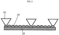
- FIG. 2 shows an exemplary flexible light field camera for optical receivers 30.
- the shape of the array is configured to best integrate information from one or more observed transceivers by warping the array 20 from flat to a hemispherical or a cylindrical surface.
- the light fields at the center of the array do not change, but those at the edge are altered to view light 10 more to the side of the array and less towards the center of the array.
- the mapping between light direction 10 and subarray 30 position becomes different at different positions on the whole array 20.
- a transceiver off to one side can be brought into view, whilst maintaining viewing of the transceivers already being monitored, albeit with less information integration between array elements and, therefore, decreased signal to noise.
- the method is for a local communications network having at least two transceiver nodes, wherein each transceiver node comprises an optical emitter, a reconfigurable optical receiver, a receiver configurer, an estimator algorithm, a receiver reconfiguration procedure, and a topology planning algorithm.
- each transceiver node comprises an optical emitter, a reconfigurable optical receiver, a receiver configurer, an estimator algorithm, a receiver reconfiguration procedure, and a topology planning algorithm.
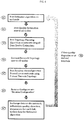
- each transceiver node executes its estimator algorithm (S1) and generates a signal quality estimation, which is then communicated to the other transceiver nodes (S2).
- the topology planning algorithm is executed on the network using all the local data quality estimations (S3).
- S3 local data quality estimations
- S4 all nodes
- each node executes the receiver reconfiguration procedure using the current network topology (S5). Then, the receivers are configured using the receiver configuration for the current network topology (S6).
- the nodes continue to exchange data (S7), e.g. collect data quality, direction, distance etc. for each link, update data for estimator algorithm. If, at any moment, data quality between any of the nodes is degraded sufficiently (S8), then the process, steps S1 to S6, is repeated or if a specific time interval is reached, the process is also repeated.
Landscapes
- Engineering & Computer Science (AREA)
- Physics & Mathematics (AREA)
- Electromagnetism (AREA)
- Computer Networks & Wireless Communication (AREA)
- Signal Processing (AREA)
- Computing Systems (AREA)
- Optical Communication System (AREA)
Abstract
Description
- The invention relates to a local communications network, a transceiver node for use in a local communications network, and a method for use in a local communications network having at least two transceiver nodes and a topology planning algorithm.
- Light field cameras organize light received onto their sensor array as a 4D field of position and light direction. This is performed, for example, by locating a microlens above a patch of the pixel array. The microlens focuses light from a small range of directions onto a position under the microlens, i.e. at a certain position light incidence angle is converted into a local position array.
-
Fig. 1 shows an example of how the specific angles map to different pixel positions within the subarrays. Animage forming lens 1 focuses a standard camera image onto thisarray 2. - Light is focused onto the array in a normal camera fashion. Information from the camera can be organized into different types of images, for example an image representing a single direction, or a single focal plane, by selecting the data from different positions within the subarrays. Alternatively, data from across the whole array can be integrated to produce, for example the summed light from a specific direction.
- A number of different technologies are becoming available to construct high resolution, multipixel image sensor arrays on flexible substrates, i.e. flexible sensor arrays. These substrates can be bent whilst continuing to act as imagers.
- If a transceiver is off to the side of a sensor and cannot be imaged, then the sensor will have to be moved (have its viewing angle changed) to bring that transceiver into view. The relationship between light angle and absolute angle of the light incident on the sensor can be altered by changing the direction of the camera (naturally). However, this causes an equal change across all the light direction fields and the total angle of view of the sensor remains the same. But if the shape of the light field array surface is changed, then the angle to position function for different parts of the array will change differently.
- It is an object of the invention to provide a local communications network comprising at least two transceiver nodes, a transceiver node for use in a local communications network, and a method for use in a local communications network taking into account the above aforementioned problems.
- This object is achieved with the features of the independent claims.
- A local communications network according to the invention comprises at least two transceiver nodes and a topology planning algorithm. Each transceiver node comprises an optical emitter, a reconfigurable optical receiver, a receiver configurer, an estimator algorithm, and a receiver reconfiguration procedure. The topology planning algorithm is configured to run on one or more transceiver nodes, to take a set of Data Quality Estimations from all transceiver nodes, choose an optimal network topology which maximizes overall network data rates, and output the result as a Current Network Topology, which is transmitted to all local nodes.
- The optical emitter may be configured to direct a light beam modulated by output data at the other transceiver nodes.
- The optical receiver may comprise a light field camera configured to integrate light collected from each different emitter and to demodulate it to produce input data, a plurality of direction actuators configured to move the camera in pitch and yaw, and a plurality of warping actuators configured to warp the sensor surface of the light field camera between different shapes.
- In a preferred embodiment, the receiver configurer may be configured to take a defined receiver configuration and to set the values of the direction actuators and warping actuators to those required in that configuration.
- The estimator algorithm may be configured to determine the anticipated signal quality of links to other nodes at different settings of its confirmation parameters, based on its knowledge of the data rates to those nodes experienced in the past and on known geometric effects of the changes in configuration and which is further configured to generate and to communicate to all the other nodes a data quality estimation describing this.
- The receiver reconfiguration procedure may be configured to take the Current Network Topology, to choose the receiver configuration that maximizes data rates for links within the topology whilst ignoring links not in the topology, and to send this receiver configuration to the receiver configurer.
- A transceiver node for use in a local communications network, wherein the receiver node comprises an optical emitter, a reconfigurable optical receiver, a receiver configurer, an estimator algorithm, and a receiver reconfiguration procedure. The optical receiver comprises a light field camera configured to integrate light collected from each different emitter and to demodulate it to produce input data, a plurality of direction actuators configured to move the camera in pitch and yaw, and a plurality of warping actuators configured to warp the sensor surface of the light field camera between different shapes.
- The receiver configurer may be configured to take a defined receiver configuration and to set the values of the direction actuators and warping actuators to those required in that configuration.
- The receiver reconfiguration procedure may be configured to take a Current Network Topology, to choose the receiver configuration that maximizes data rates for links within the topology whilst ignoring links not in the topology, and to send this receiver configuration to the receiver configurer.
- According to the invention, a method for a local communications network having at least two transceiver nodes and a topology planning algorithm, wherein each transceiver node comprises an optical emitter, a reconfigurable optical receiver, a receiver configurer, an estimator algorithm, a receiver reconfiguration procedure, said method comprising the steps of: a) each transceiver node executing its estimator algorithm and generating a signal quality estimation, which is communicated to other transceiver nodes, b) the topology planning algorithm executing on the network using all the local data quality estimations and generating a current network topology and communicating the generated current network topology to all nodes, c) each node executing the receiver reconfiguration procedure and the receivers are configured using the receiver configuration for the current network topology, and repeating steps a) to c), if while exchanging data the data quality between any nodes degrades sufficiently or a specific time interval is reached.
- The issues being solved by this invention include: a network of local transceivers needs to organize itself to maintain the best communications possible, given that communication between certain transceivers may be obscured by objects between them, or two transceivers may be on the same line of sight from another transceiver, or haze and mist might degrade a communication link; and light field cameras can improve the ability to differentiate multiple observer emitters in the field of view, but sometimes a greater field of view or better angular rather than spatial resolution may improve this still further, in certain circumstances. Therefore, there are benefits to light field cameras with the ability to modify their imaging configuration when detecting signals from optical emitters.
- Light field cameras detect light and are able to determine the position of the objects in the field of view (x, y) and the direction of light incident on the sensor at that position (θ, φ). They are only able to receive data from emitters in their field of view and the ability to separate different transceivers may not be possible even with their improved ability to generate images at e.g. different focal depths.
- The data from a light field camera can be reorganized, e.g. by integrating different data from the 4D array, to integrate information at different focal depths, light directions or positions.
- The light field camera can be moved laterally or vertically, using a suitable actuator, to change the field of view of that camera.
- If the light field sensor is manufactured using a technique which allows a flexible sensor array, the shape of the imaging surface in a light field camera can also be altered so that the relationship between light direction and position on the light direction subarray varies across the camera, e.g. by warping, using an actuator, the imaging surface from flat to, for example, cylindrical or hemispherical. These changes can improve the ability to increase the field of view or to separate different transceivers according to their position and the angle of light from them, e.g. to separate their distance away.
- Local transceiver networks can reconfigure themselves if required, for example to maximize data transmission rates, by routing information to that node through one or more other nodes. Given that changes to the arrangement of receivers, e.g. their orientation, may result in improvements to one link but degradation of another link, different choices of the network topology and therefore receiver configuration of each node (seeking to maximize the quality of the data link between those connections in the topology but ignoring those connections not in the topology) may result in significantly different overall network data rates.
- The optimal choice of overall network topology can be determined if the quality of the set of inter-node links for all the local transceivers given their different receiver configurations is known.
- Given a specific network topology, a receiver can configure itself to maximize the quality of the links active in that topology whilst ignoring the links absent in the topology. Therefore, a process can be performed which continuously reconfigures the network and the receiver configurations of each node in order to maximize data transmission rates. According to the present invention, this process can be summarized as follows: a) first each transceiver estimates the communication data quality to the other local transceivers for different light field warping configurations of its receiver; b) secondly these estimates are communicated to the rest of local transceivers; c) thirdly based on the estimates from all the local transceivers a network topology is chosen which maximizes data transmission rates (e.g. also taking into account the current data communications requirements between nodes); d) fourthly this chosen topology is communicated to all the local transceivers; e) lastly each transceiver optimizes its light field warping receiver configuration to maximize the quality of all the links within that topology whilst ignoring the links not in the topology.
- Light field cameras with flexible light sensor arrays can be reconfigured by changing their direction and shape to improve reception or separation with other emitters in specific directions and distances, though there will be a tradeoff in terms of possibly worsening reception for other emitters.
- Networks can continually maintain optimal data rates taking advantage of the properties of the advanced optical receivers and their ability to optimize themselves for certain connections.
-
- FIG. 1
- is an example of how the specific angles map to different pixel positions within the subarrays.
- FIG. 2
- is an example of a flexible light field camera for optical receivers with a flat surface.
- FIG. 3
- is an example of a flexible light field camera for optical receivers with a hemispherical surface.
- FIG. 4
- is a flowchart summarizing the main method.
-
FIG. 2 shows an exemplary flexible light field camera foroptical receivers 30. The shape of the array is configured to best integrate information from one or more observed transceivers by warping thearray 20 from flat to a hemispherical or a cylindrical surface. The light fields at the center of the array do not change, but those at the edge are altered to viewlight 10 more to the side of the array and less towards the center of the array. - By changing the shape of the
array 20, as shown inFIG. 3 , the mapping betweenlight direction 10 and subarray 30 position becomes different at different positions on thewhole array 20. In this way, a transceiver off to one side can be brought into view, whilst maintaining viewing of the transceivers already being monitored, albeit with less information integration between array elements and, therefore, decreased signal to noise. - Hereunder, an exemplary method will be described in detail with reference to
FIG. 4 . - According to the invention, the method is for a local communications network having at least two transceiver nodes, wherein each transceiver node comprises an optical emitter, a reconfigurable optical receiver, a receiver configurer, an estimator algorithm, a receiver reconfiguration procedure, and a topology planning algorithm. According to the embodiment illustrated in
Fig. 4 , the method comprising the following steps. - First each transceiver node executes its estimator algorithm (S1) and generates a signal quality estimation, which is then communicated to the other transceiver nodes (S2).
- Then, the topology planning algorithm is executed on the network using all the local data quality estimations (S3). As a result, a current network topology is generated and communicated to all nodes (S4).
- After the step S4, each node executes the receiver reconfiguration procedure using the current network topology (S5). Then, the receivers are configured using the receiver configuration for the current network topology (S6).
- At this stage, the nodes continue to exchange data (S7), e.g. collect data quality, direction, distance etc. for each link, update data for estimator algorithm. If, at any moment, data quality between any of the nodes is degraded sufficiently (S8), then the process, steps S1 to S6, is repeated or if a specific time interval is reached, the process is also repeated.
- While the invention has been illustrated and described in detail in the drawings and foregoing description, such illustration and description are to be considered illustrative or exemplary and not restrictive. It will be understood that changes and modifications may be made by those of ordinary skill within the scope of the following claims. In particular, the present invention covers further embodiments with any combination of features from different embodiments described above and below.
- Furthermore, in the claims the word "comprising" does not exclude other elements or steps, and the indefinite article "a" or "an" does not exclude a plurality. A single unit may fulfil the functions of several features recited in the claims. The terms "essentially", "about", "approximately" and the like in connection with an attribute or a value particularly also define exactly the attribute or exactly the value, respectively. Any reference signs in the claims should not be construed as limiting the scope.
Claims (10)
- A local communications network comprising:at least two transceiver nodes, wherein each transceiver node comprises an optical emitter, a reconfigurable optical receiver, a receiver configurer, an estimator algorithm, and a receiver reconfiguration procedure; anda topology planning algorithm configured to run on one or more transceiver nodes, to take a set of Data Quality Estimations from all transceiver nodes, choose an optimal network topology which maximizes overall network data rates, and output the result as a current network topology which is transmitted to all local nodes.
- The local communications network of claim 1, wherein the optical emitter is configured to direct a light beam modulated by output data at the other transceiver nodes.
- The local communications network of claims 1 or 2, wherein the optical receiver comprises:a light field camera configured to integrate light collected from each different emitter and to demodulate it to produce input data,a plurality of direction actuators configured to move the camera in pitch and yaw, anda plurality of warping actuators configured to warp the sensor surface of the light field camera between different shapes.
- The local communications network of claims 1 to 3, wherein the receiver configurer is configured to take a defined receiver configuration and to set the values of the direction actuators and warping actuators to those required in that configuration.
- The local communications network of claims 1 to 4, wherein the estimator algorithm is configured to determine the anticipated signal quality of links to other nodes at different settings of its confirmation parameters, based on its knowledge of the data rates to those nodes experienced in the past and on known geometric effects of the changes in configuration and which is further configured to generate and to communicate to all the other nodes a data quality estimation describing this.
- The local communications network of claims 1 to 5, wherein the receiver reconfiguration procedure is configured to take the current network topology, to choose the receiver configuration that maximizes data rates for links within the topology whilst ignoring links not in the topology, and to send this receiver configuration to the receiver configurer.
- A transceiver node for use in a local communications network, the transceiver node comprising:an optical emitter, a reconfigurable optical receiver, a receiver configurer, an estimator algorithm, and a receiver reconfiguration procedure, wherein the optical receiver comprises:a light field camera configured to integrate light collected from each different emitter and to demodulate it to produce input data,a plurality of direction actuators configured to move the camera in pitch and yaw, anda plurality of warping actuators configured to warp the sensor surface of the light field camera between different shapes.
- The transceiver node of claim 7, wherein the receiver configurer is configured to take a defined receiver configuration and to set the values of the direction actuators and warping actuators to those required in that configuration.
- The transceiver node of any of claims 7 or 8, wherein the receiver reconfiguration procedure is configured to take a current network topology, to choose the receiver configuration that maximizes data rates for links within the topology whilst ignoring links not in the topology, and to send this receiver configuration to the receiver configurer.
- A method for a local communications network having at least two transceiver nodes, wherein each transceiver node comprises an optical emitter, a reconfigurable optical receiver, a receiver configurer, an estimator algorithm, a receiver reconfiguration procedure, and a topology planning algorithm, said method comprising the steps of:a) each transceiver node executing its estimator algorithm and generating a signal quality estimation, which is communicated to other transceiver nodes,b) the topology planning algorithm executing on the network using all the local data quality estimations and generating a current network topology and communicating the generated current network topology to all nodes,c) each node executing the receiver reconfiguration procedure and the receivers are configured using the receiver configuration for the current network topology, andrepeating steps a) to c), if while exchanging data the data quality between any nodes degrades sufficiently or a specific time interval is reached.
Priority Applications (1)
| Application Number | Priority Date | Filing Date | Title |
|---|---|---|---|
| EP17182765.2A EP3435558B1 (en) | 2017-07-24 | 2017-07-24 | Local communication network, transceiver node, and method |
Applications Claiming Priority (1)
| Application Number | Priority Date | Filing Date | Title |
|---|---|---|---|
| EP17182765.2A EP3435558B1 (en) | 2017-07-24 | 2017-07-24 | Local communication network, transceiver node, and method |
Publications (2)
| Publication Number | Publication Date |
|---|---|
| EP3435558A1 true EP3435558A1 (en) | 2019-01-30 |
| EP3435558B1 EP3435558B1 (en) | 2021-02-17 |
Family
ID=59631547
Family Applications (1)
| Application Number | Title | Priority Date | Filing Date |
|---|---|---|---|
| EP17182765.2A Active EP3435558B1 (en) | 2017-07-24 | 2017-07-24 | Local communication network, transceiver node, and method |
Country Status (1)
| Country | Link |
|---|---|
| EP (1) | EP3435558B1 (en) |
Citations (6)
| Publication number | Priority date | Publication date | Assignee | Title |
|---|---|---|---|---|
| EP1545027A1 (en) * | 2003-12-18 | 2005-06-22 | Alcatel | Robot communication system |
| WO2012167135A1 (en) * | 2011-06-03 | 2012-12-06 | Skyfiber, Inc | Active tracking for free-space optical communication systems |
| JP2014050033A (en) * | 2012-09-03 | 2014-03-17 | Kogakuin Univ | Space optical transmission system |
| WO2014053175A1 (en) * | 2012-10-03 | 2014-04-10 | Telefonaktiebolaget L M Ericsson (Publ) | Optical path validation method |
| US20150023666A1 (en) * | 2013-07-18 | 2015-01-22 | Fujitsu Limited | Network designing apparatus, network designing method, and network designing program |
| US20160086994A1 (en) * | 2014-09-19 | 2016-03-24 | Microsoft Corporation | Image Sensor Bending Using Tension |
-
2017
- 2017-07-24 EP EP17182765.2A patent/EP3435558B1/en active Active
Patent Citations (6)
| Publication number | Priority date | Publication date | Assignee | Title |
|---|---|---|---|---|
| EP1545027A1 (en) * | 2003-12-18 | 2005-06-22 | Alcatel | Robot communication system |
| WO2012167135A1 (en) * | 2011-06-03 | 2012-12-06 | Skyfiber, Inc | Active tracking for free-space optical communication systems |
| JP2014050033A (en) * | 2012-09-03 | 2014-03-17 | Kogakuin Univ | Space optical transmission system |
| WO2014053175A1 (en) * | 2012-10-03 | 2014-04-10 | Telefonaktiebolaget L M Ericsson (Publ) | Optical path validation method |
| US20150023666A1 (en) * | 2013-07-18 | 2015-01-22 | Fujitsu Limited | Network designing apparatus, network designing method, and network designing program |
| US20160086994A1 (en) * | 2014-09-19 | 2016-03-24 | Microsoft Corporation | Image Sensor Bending Using Tension |
Also Published As
| Publication number | Publication date |
|---|---|
| EP3435558B1 (en) | 2021-02-17 |
Similar Documents
| Publication | Publication Date | Title |
|---|---|---|
| JP6959316B2 (en) | High-speed free space optical communication | |
| US11456532B2 (en) | Modular optical phased array | |
| US8009223B2 (en) | Image sensor, focus detection device, focus adjustment device and image-capturing apparatus | |
| US20170350965A1 (en) | Lidar systems with expanded fields of view on a planar substrate | |
| US20190089460A1 (en) | Co-prime optical transceiver array | |
| KR20150054568A (en) | A depth sensor, and a method of operating the same | |
| US20170234977A1 (en) | Lidar system and multiple detection signal processing method thereof | |
| US8836765B2 (en) | Apparatus and method for generating a fully focused image by using a camera equipped with a multi-color filter aperture | |
| Ashok et al. | Characterizing multiplexing and diversity in visual MIMO | |
| KR20200122367A (en) | System for multi-channel spread-beam optical wireless communication | |
| KR102781524B1 (en) | Frequency gradient metasurface device based on fast beam steering system and method therefor | |
| JP5257477B2 (en) | Optical space communication device, communication method therefor, and optical space communication system | |
| EP4333445A1 (en) | Electronic device and control method therefor | |
| US11855690B2 (en) | Sloping single point optical aggregation | |
| JP5979134B2 (en) | Image processing apparatus and image processing program | |
| US10580807B2 (en) | Color pixel and range pixel combination unit | |
| EP3435558B1 (en) | Local communication network, transceiver node, and method | |
| WO2022241333A2 (en) | System and methods for depth sensing with auxiliary information by a monocular camera | |
| US6661546B1 (en) | Multi-aperture holographic optical element for illumination sensing in a free space optical communication system | |
| KR20150081732A (en) | System of tracking moving-object | |
| US20200154043A1 (en) | Large Field of View Multi-Camera Endoscopic Apparatus with Omni-Directional Illumination | |
| CN117544247A (en) | Method and device for realizing light weight of spatial information center network | |
| JP2009177654A (en) | Spatial optical communication device and method | |
| CN113726431A (en) | Unmanned aerial vehicle visible light communication device and method based on camera assistance | |
| KR20230037382A (en) | Electronic device and control method thereof |
Legal Events
| Date | Code | Title | Description |
|---|---|---|---|
| PUAI | Public reference made under article 153(3) epc to a published international application that has entered the european phase |
Free format text: ORIGINAL CODE: 0009012 |
|
| STAA | Information on the status of an ep patent application or granted ep patent |
Free format text: STATUS: REQUEST FOR EXAMINATION WAS MADE |
|
| 17P | Request for examination filed |
Effective date: 20180607 |
|
| AK | Designated contracting states |
Kind code of ref document: A1 Designated state(s): AL AT BE BG CH CY CZ DE DK EE ES FI FR GB GR HR HU IE IS IT LI LT LU LV MC MK MT NL NO PL PT RO RS SE SI SK SM TR |
|
| AX | Request for extension of the european patent |
Extension state: BA ME |
|
| GRAP | Despatch of communication of intention to grant a patent |
Free format text: ORIGINAL CODE: EPIDOSNIGR1 |
|
| STAA | Information on the status of an ep patent application or granted ep patent |
Free format text: STATUS: GRANT OF PATENT IS INTENDED |
|
| INTG | Intention to grant announced |
Effective date: 20201008 |
|
| GRAS | Grant fee paid |
Free format text: ORIGINAL CODE: EPIDOSNIGR3 |
|
| GRAA | (expected) grant |
Free format text: ORIGINAL CODE: 0009210 |
|
| STAA | Information on the status of an ep patent application or granted ep patent |
Free format text: STATUS: THE PATENT HAS BEEN GRANTED |
|
| AK | Designated contracting states |
Kind code of ref document: B1 Designated state(s): AL AT BE BG CH CY CZ DE DK EE ES FI FR GB GR HR HU IE IS IT LI LT LU LV MC MK MT NL NO PL PT RO RS SE SI SK SM TR |
|
| REG | Reference to a national code |
Ref country code: GB Ref legal event code: FG4D |
|
| RIN1 | Information on inventor provided before grant (corrected) |
Inventor name: WALKER, NICHOLAS Inventor name: BUNGE, CHRISTIAN-ALEXANDER Inventor name: NOLAN, JULIAN CHARLES |
|
| REG | Reference to a national code |
Ref country code: CH Ref legal event code: EP |
|
| REG | Reference to a national code |
Ref country code: DE Ref legal event code: R096 Ref document number: 602017032529 Country of ref document: DE |
|
| REG | Reference to a national code |
Ref country code: AT Ref legal event code: REF Ref document number: 1362868 Country of ref document: AT Kind code of ref document: T Effective date: 20210315 |
|
| REG | Reference to a national code |
Ref country code: IE Ref legal event code: FG4D |
|
| REG | Reference to a national code |
Ref country code: LT Ref legal event code: MG9D |
|
| REG | Reference to a national code |
Ref country code: NL Ref legal event code: MP Effective date: 20210217 |
|
| PG25 | Lapsed in a contracting state [announced via postgrant information from national office to epo] |
Ref country code: BG Free format text: LAPSE BECAUSE OF FAILURE TO SUBMIT A TRANSLATION OF THE DESCRIPTION OR TO PAY THE FEE WITHIN THE PRESCRIBED TIME-LIMIT Effective date: 20210517 Ref country code: LT Free format text: LAPSE BECAUSE OF FAILURE TO SUBMIT A TRANSLATION OF THE DESCRIPTION OR TO PAY THE FEE WITHIN THE PRESCRIBED TIME-LIMIT Effective date: 20210217 Ref country code: GR Free format text: LAPSE BECAUSE OF FAILURE TO SUBMIT A TRANSLATION OF THE DESCRIPTION OR TO PAY THE FEE WITHIN THE PRESCRIBED TIME-LIMIT Effective date: 20210518 Ref country code: FI Free format text: LAPSE BECAUSE OF FAILURE TO SUBMIT A TRANSLATION OF THE DESCRIPTION OR TO PAY THE FEE WITHIN THE PRESCRIBED TIME-LIMIT Effective date: 20210217 Ref country code: HR Free format text: LAPSE BECAUSE OF FAILURE TO SUBMIT A TRANSLATION OF THE DESCRIPTION OR TO PAY THE FEE WITHIN THE PRESCRIBED TIME-LIMIT Effective date: 20210217 Ref country code: NO Free format text: LAPSE BECAUSE OF FAILURE TO SUBMIT A TRANSLATION OF THE DESCRIPTION OR TO PAY THE FEE WITHIN THE PRESCRIBED TIME-LIMIT Effective date: 20210517 Ref country code: PT Free format text: LAPSE BECAUSE OF FAILURE TO SUBMIT A TRANSLATION OF THE DESCRIPTION OR TO PAY THE FEE WITHIN THE PRESCRIBED TIME-LIMIT Effective date: 20210617 |
|
| REG | Reference to a national code |
Ref country code: AT Ref legal event code: MK05 Ref document number: 1362868 Country of ref document: AT Kind code of ref document: T Effective date: 20210217 |
|
| PG25 | Lapsed in a contracting state [announced via postgrant information from national office to epo] |
Ref country code: SE Free format text: LAPSE BECAUSE OF FAILURE TO SUBMIT A TRANSLATION OF THE DESCRIPTION OR TO PAY THE FEE WITHIN THE PRESCRIBED TIME-LIMIT Effective date: 20210217 Ref country code: LV Free format text: LAPSE BECAUSE OF FAILURE TO SUBMIT A TRANSLATION OF THE DESCRIPTION OR TO PAY THE FEE WITHIN THE PRESCRIBED TIME-LIMIT Effective date: 20210217 Ref country code: RS Free format text: LAPSE BECAUSE OF FAILURE TO SUBMIT A TRANSLATION OF THE DESCRIPTION OR TO PAY THE FEE WITHIN THE PRESCRIBED TIME-LIMIT Effective date: 20210217 Ref country code: PL Free format text: LAPSE BECAUSE OF FAILURE TO SUBMIT A TRANSLATION OF THE DESCRIPTION OR TO PAY THE FEE WITHIN THE PRESCRIBED TIME-LIMIT Effective date: 20210217 Ref country code: NL Free format text: LAPSE BECAUSE OF FAILURE TO SUBMIT A TRANSLATION OF THE DESCRIPTION OR TO PAY THE FEE WITHIN THE PRESCRIBED TIME-LIMIT Effective date: 20210217 |
|
| PG25 | Lapsed in a contracting state [announced via postgrant information from national office to epo] |
Ref country code: IS Free format text: LAPSE BECAUSE OF FAILURE TO SUBMIT A TRANSLATION OF THE DESCRIPTION OR TO PAY THE FEE WITHIN THE PRESCRIBED TIME-LIMIT Effective date: 20210617 |
|
| PG25 | Lapsed in a contracting state [announced via postgrant information from national office to epo] |
Ref country code: SM Free format text: LAPSE BECAUSE OF FAILURE TO SUBMIT A TRANSLATION OF THE DESCRIPTION OR TO PAY THE FEE WITHIN THE PRESCRIBED TIME-LIMIT Effective date: 20210217 Ref country code: AT Free format text: LAPSE BECAUSE OF FAILURE TO SUBMIT A TRANSLATION OF THE DESCRIPTION OR TO PAY THE FEE WITHIN THE PRESCRIBED TIME-LIMIT Effective date: 20210217 Ref country code: EE Free format text: LAPSE BECAUSE OF FAILURE TO SUBMIT A TRANSLATION OF THE DESCRIPTION OR TO PAY THE FEE WITHIN THE PRESCRIBED TIME-LIMIT Effective date: 20210217 Ref country code: CZ Free format text: LAPSE BECAUSE OF FAILURE TO SUBMIT A TRANSLATION OF THE DESCRIPTION OR TO PAY THE FEE WITHIN THE PRESCRIBED TIME-LIMIT Effective date: 20210217 |
|
| REG | Reference to a national code |
Ref country code: DE Ref legal event code: R097 Ref document number: 602017032529 Country of ref document: DE |
|
| PG25 | Lapsed in a contracting state [announced via postgrant information from national office to epo] |
Ref country code: SK Free format text: LAPSE BECAUSE OF FAILURE TO SUBMIT A TRANSLATION OF THE DESCRIPTION OR TO PAY THE FEE WITHIN THE PRESCRIBED TIME-LIMIT Effective date: 20210217 Ref country code: RO Free format text: LAPSE BECAUSE OF FAILURE TO SUBMIT A TRANSLATION OF THE DESCRIPTION OR TO PAY THE FEE WITHIN THE PRESCRIBED TIME-LIMIT Effective date: 20210217 Ref country code: DK Free format text: LAPSE BECAUSE OF FAILURE TO SUBMIT A TRANSLATION OF THE DESCRIPTION OR TO PAY THE FEE WITHIN THE PRESCRIBED TIME-LIMIT Effective date: 20210217 |
|
| PLBE | No opposition filed within time limit |
Free format text: ORIGINAL CODE: 0009261 |
|
| STAA | Information on the status of an ep patent application or granted ep patent |
Free format text: STATUS: NO OPPOSITION FILED WITHIN TIME LIMIT |
|
| 26N | No opposition filed |
Effective date: 20211118 |
|
| PG25 | Lapsed in a contracting state [announced via postgrant information from national office to epo] |
Ref country code: AL Free format text: LAPSE BECAUSE OF FAILURE TO SUBMIT A TRANSLATION OF THE DESCRIPTION OR TO PAY THE FEE WITHIN THE PRESCRIBED TIME-LIMIT Effective date: 20210217 Ref country code: ES Free format text: LAPSE BECAUSE OF FAILURE TO SUBMIT A TRANSLATION OF THE DESCRIPTION OR TO PAY THE FEE WITHIN THE PRESCRIBED TIME-LIMIT Effective date: 20210217 |
|
| PG25 | Lapsed in a contracting state [announced via postgrant information from national office to epo] |
Ref country code: SI Free format text: LAPSE BECAUSE OF FAILURE TO SUBMIT A TRANSLATION OF THE DESCRIPTION OR TO PAY THE FEE WITHIN THE PRESCRIBED TIME-LIMIT Effective date: 20210217 |
|
| REG | Reference to a national code |
Ref country code: CH Ref legal event code: PL |
|
| PG25 | Lapsed in a contracting state [announced via postgrant information from national office to epo] |
Ref country code: MC Free format text: LAPSE BECAUSE OF FAILURE TO SUBMIT A TRANSLATION OF THE DESCRIPTION OR TO PAY THE FEE WITHIN THE PRESCRIBED TIME-LIMIT Effective date: 20210217 |
|
| REG | Reference to a national code |
Ref country code: BE Ref legal event code: MM Effective date: 20210731 |
|
| PG25 | Lapsed in a contracting state [announced via postgrant information from national office to epo] |
Ref country code: LI Free format text: LAPSE BECAUSE OF NON-PAYMENT OF DUE FEES Effective date: 20210731 Ref country code: IT Free format text: LAPSE BECAUSE OF FAILURE TO SUBMIT A TRANSLATION OF THE DESCRIPTION OR TO PAY THE FEE WITHIN THE PRESCRIBED TIME-LIMIT Effective date: 20210217 Ref country code: CH Free format text: LAPSE BECAUSE OF NON-PAYMENT OF DUE FEES Effective date: 20210731 |
|
| PG25 | Lapsed in a contracting state [announced via postgrant information from national office to epo] |
Ref country code: IS Free format text: LAPSE BECAUSE OF FAILURE TO SUBMIT A TRANSLATION OF THE DESCRIPTION OR TO PAY THE FEE WITHIN THE PRESCRIBED TIME-LIMIT Effective date: 20210617 Ref country code: LU Free format text: LAPSE BECAUSE OF NON-PAYMENT OF DUE FEES Effective date: 20210724 |
|
| PG25 | Lapsed in a contracting state [announced via postgrant information from national office to epo] |
Ref country code: IE Free format text: LAPSE BECAUSE OF NON-PAYMENT OF DUE FEES Effective date: 20210724 Ref country code: BE Free format text: LAPSE BECAUSE OF NON-PAYMENT OF DUE FEES Effective date: 20210731 |
|
| PG25 | Lapsed in a contracting state [announced via postgrant information from national office to epo] |
Ref country code: CY Free format text: LAPSE BECAUSE OF FAILURE TO SUBMIT A TRANSLATION OF THE DESCRIPTION OR TO PAY THE FEE WITHIN THE PRESCRIBED TIME-LIMIT Effective date: 20210217 |
|
| PG25 | Lapsed in a contracting state [announced via postgrant information from national office to epo] |
Ref country code: HU Free format text: LAPSE BECAUSE OF FAILURE TO SUBMIT A TRANSLATION OF THE DESCRIPTION OR TO PAY THE FEE WITHIN THE PRESCRIBED TIME-LIMIT; INVALID AB INITIO Effective date: 20170724 |
|
| PG25 | Lapsed in a contracting state [announced via postgrant information from national office to epo] |
Ref country code: MK Free format text: LAPSE BECAUSE OF FAILURE TO SUBMIT A TRANSLATION OF THE DESCRIPTION OR TO PAY THE FEE WITHIN THE PRESCRIBED TIME-LIMIT Effective date: 20210217 |
|
| PG25 | Lapsed in a contracting state [announced via postgrant information from national office to epo] |
Ref country code: MT Free format text: LAPSE BECAUSE OF FAILURE TO SUBMIT A TRANSLATION OF THE DESCRIPTION OR TO PAY THE FEE WITHIN THE PRESCRIBED TIME-LIMIT Effective date: 20210217 |
|
| PGFP | Annual fee paid to national office [announced via postgrant information from national office to epo] |
Ref country code: DE Payment date: 20250722 Year of fee payment: 9 |
|
| PGFP | Annual fee paid to national office [announced via postgrant information from national office to epo] |
Ref country code: GB Payment date: 20250724 Year of fee payment: 9 |
|
| PGFP | Annual fee paid to national office [announced via postgrant information from national office to epo] |
Ref country code: FR Payment date: 20250723 Year of fee payment: 9 |
|
| PG25 | Lapsed in a contracting state [announced via postgrant information from national office to epo] |
Ref country code: TR Free format text: LAPSE BECAUSE OF FAILURE TO SUBMIT A TRANSLATION OF THE DESCRIPTION OR TO PAY THE FEE WITHIN THE PRESCRIBED TIME-LIMIT Effective date: 20210217 |