EP3435537B1 - Fan and rotational speed control method thereof - Google Patents
Fan and rotational speed control method thereof Download PDFInfo
- Publication number
- EP3435537B1 EP3435537B1 EP18178858.9A EP18178858A EP3435537B1 EP 3435537 B1 EP3435537 B1 EP 3435537B1 EP 18178858 A EP18178858 A EP 18178858A EP 3435537 B1 EP3435537 B1 EP 3435537B1
- Authority
- EP
- European Patent Office
- Prior art keywords
- rotational speed
- duty cycle
- cycle value
- target
- motor
- Prior art date
- Legal status (The legal status is an assumption and is not a legal conclusion. Google has not performed a legal analysis and makes no representation as to the accuracy of the status listed.)
- Active
Links
Images


Classifications
-
- F—MECHANICAL ENGINEERING; LIGHTING; HEATING; WEAPONS; BLASTING
- F04—POSITIVE - DISPLACEMENT MACHINES FOR LIQUIDS; PUMPS FOR LIQUIDS OR ELASTIC FLUIDS
- F04D—NON-POSITIVE-DISPLACEMENT PUMPS
- F04D27/00—Control, e.g. regulation, of pumps, pumping installations or pumping systems specially adapted for elastic fluids
- F04D27/004—Control, e.g. regulation, of pumps, pumping installations or pumping systems specially adapted for elastic fluids by varying driving speed
-
- H—ELECTRICITY
- H02—GENERATION; CONVERSION OR DISTRIBUTION OF ELECTRIC POWER
- H02P—CONTROL OR REGULATION OF ELECTRIC MOTORS, ELECTRIC GENERATORS OR DYNAMO-ELECTRIC CONVERTERS; CONTROLLING TRANSFORMERS, REACTORS OR CHOKE COILS
- H02P7/00—Arrangements for regulating or controlling the speed or torque of electric DC motors
- H02P7/06—Arrangements for regulating or controlling the speed or torque of electric DC motors for regulating or controlling an individual DC dynamo-electric motor by varying field or armature current
- H02P7/18—Arrangements for regulating or controlling the speed or torque of electric DC motors for regulating or controlling an individual DC dynamo-electric motor by varying field or armature current by master control with auxiliary power
- H02P7/24—Arrangements for regulating or controlling the speed or torque of electric DC motors for regulating or controlling an individual DC dynamo-electric motor by varying field or armature current by master control with auxiliary power using discharge tubes or semiconductor devices
- H02P7/28—Arrangements for regulating or controlling the speed or torque of electric DC motors for regulating or controlling an individual DC dynamo-electric motor by varying field or armature current by master control with auxiliary power using discharge tubes or semiconductor devices using semiconductor devices
- H02P7/285—Arrangements for regulating or controlling the speed or torque of electric DC motors for regulating or controlling an individual DC dynamo-electric motor by varying field or armature current by master control with auxiliary power using discharge tubes or semiconductor devices using semiconductor devices controlling armature supply only
- H02P7/29—Arrangements for regulating or controlling the speed or torque of electric DC motors for regulating or controlling an individual DC dynamo-electric motor by varying field or armature current by master control with auxiliary power using discharge tubes or semiconductor devices using semiconductor devices controlling armature supply only using pulse modulation
-
- H—ELECTRICITY
- H02—GENERATION; CONVERSION OR DISTRIBUTION OF ELECTRIC POWER
- H02P—CONTROL OR REGULATION OF ELECTRIC MOTORS, ELECTRIC GENERATORS OR DYNAMO-ELECTRIC CONVERTERS; CONTROLLING TRANSFORMERS, REACTORS OR CHOKE COILS
- H02P6/00—Arrangements for controlling synchronous motors or other dynamo-electric motors using electronic commutation dependent on the rotor position; Electronic commutators therefor
- H02P6/08—Arrangements for controlling the speed or torque of a single motor
Definitions
- the present invention relates to a fan and a rotational speed control method thereof and, more particularly, to a fan capable of automatically adjusting the rotational speed without reference to a motor operating current, and a rotational speed control method of the fan.
- a conventional air-exchange fan (or so-called ventilator) can be connected to a plurality of spaces or machines via a plurality of air ducts and can be driven by a motor to rotate for driving air currents to flow for air exchange or ventilation.
- the static pressure withstood by the fan is affected by the size and quantity of the spaces to be ventilated, the length and diameter of the air ducts, etc.
- the flow rate of the fan is reduced when the static pressure increases, and the flow rate of the fan is increased when the static pressure is reduced.
- the exhaust gas discharge efficiency is low, causing damage to the machines or lack of oxygen in an open/closed space.
- the flow rate of the fan When the flow rate of the fan is larger than the desired total air discharge, pressure imbalance between the inside and the outside of the space and a waste of energy occur. Since the flow rate of the fan is positively correlated with the wind speed passing through an opening of the fan, the wind speed can be adjusted by controlling the rotational speed of the fan to thereby control the flow rate.
- Conventional methods for controlling a rotational speed of a fan requires measurement of an operating current value of the motor of the fan and the rotational speed of the fan, and algorithm is performed to maintain a stable rotational speed under different air discharge demands or to identify whether to switch to a proper rotational speed.
- reading the current value requires a serial connection of a galvanometer and the circuit to be detected, and the motor wiring must be cut during mounting or replacement of the galvanometer, leading to difficulties in use and maintenance.
- the current signal must be amplified by an amplifier and is, thus, apt to incur noise signals which must be filtered by an extra filter.
- the circuit is complicated, increasing the installation cost of the circuit.
- the accuracy of the result of the algorithm affects the stability of the rotational speed.
- U.S. Patent Public No. 2009/0309535A1 discloses a motor control apparatus and motor control method which implement an improved motor control operation of an electric motor.
- U.S. Patent Public No. 2010/0225263A1 discloses a motor driving circuit and method for driving motor, which uses pulse width modulation (PWM) to start up the motor.
- PWM pulse width modulation
- the present invention provides a method for controlling a rotational speed of a fan.
- the method refers to a corresponding relation between a variable duty cycle value and a motor rotational speed without the need of measuring the operating current value of the motor.
- the present invention provides method for controlling a rotational speed of a fan to automatically adjust the rotational speed to a proper value by cooperating with a change in the environmental pressure, avoiding insufficient air exchange amount or a waste of energy.
- a method for controlling a rotational speed of a fan according to the present invention comprises: an initialization step including using a control unit to start a motor of the fan according to an initial duty cycle value; characterised by a first constant speed step including using the control unit to compare a motor rotational speed with a first target rotational speed, wherein the duty cycle value outputted by the control unit is changed to make the motor rotational speed equal to the first target rotational speed when the motor rotational speed is different from the first target rotational speed, wherein when the motor rotational speed is equal to the first target rotational speed, it is determined whether the duty cycle value and a first target duty cycle value satisfy a first relational expression, if not, the first constant speed step is repeated; and a second constant speed step: wherein when the duty cycle value and the first target duty cycle value satisfy the first relational expression in the first constant speed step, the control unit compares the motor rotational speed with a second target rotational speed, wherein the duty cycle value outputted by the control unit is changed to make the motor rotational speed equal to the
- the method for controlling the rotational speed of the fan according to the present invention does not need to refer to the operating current of the motor for algorithm. Instead, through comparison of the motor rotational speed and adjustment of the duty cycle value, the fan maintains at a constant speed to provide a stable flow rate no matter whether the static pressure of the environment in which the fan is located changes or not.
- the duty cycle value is positively correlated with the motor rotational speed
- the first relational expression is that the duty cycle value is smaller than the first target duty cycle value
- the second relational expression is that the first target duty cycle value is larger than the second target duty cycle value
- the first target duty cycle value is larger than the second target duty cycle value.
- the duty cycle value is negatively correlated with the motor rotational speed
- the first relational expression is that the duty cycle value is larger than the first target duty cycle value
- the second relational expression is that the first target duty cycle value is smaller than the second target duty cycle value
- the first target duty cycle value is smaller than the second target duty cycle value.
- the fan is an air exchange fan connected to a plurality of open/closed spaces.
- a single fan can be used to provide air exchange for a plurality of open/closed spaces.
- the first target rotational speed, the second target rotational speed, the first target duty cycle value, the second target duty cycle value, the first relational expression, and the second relational expression are stored in the control unit.
- the control unit controls the rotational speed through the duty cycle values based on the experimental data without the need of measurement of the current value or use of a complicated algorithm, increasing the accuracy and reducing the manufacturing cost.
- control unit stores a plurality of fan characteristic curves respectively representing a plurality of different duty cycle values.
- the duty cycle values can be used to control the rotational speed without the need of measurement of the current value or use of a complicated algorithm, increasing the accuracy and reducing the manufacturing cost.
- the method proceeds from the first constant speed step to the second constant speed step according to a first hysteresis curve, and the method proceeds from the second constant speed step to the first constant speed step according to a second hysteresis curve.
- the setting of the first hysteresis curve and the second hysteresis curve can avoid excessively frequent switching of the motor rotational speed within a short period of time (which would result in damage to the motor or unstable air exchange) when the duty cycle value of the control unit approaches the first duty cycle value or the second duty cycle value.
- the accuracy is increased, and the flow rate is stable.
- control unit is a micro controller.
- control unit can store experimental data related to the fan and can proceed with operation to control and stabilize the motor rotational speed.
- control unit includes a driving circuit.
- the driving circuit is electrically connected to the motor and is configured to drive the motor.
- the control unit can output a PWM driving signal with the duty cycle value to operate the motor, thereby controlling the motor rotational speed.
- the motor includes a speed detection unit electrically connected to the control unit.
- the speed detection unit can detect and transmit a speed signal to the control unit for comparison, monitoring the motor rotational speed and assisting in stabilizing the motor rotational speed.
- control unit and the speed detection unit are integrated on a circuit board, and the circuit board is mounted in the fan or the motor.
- the hardware can be simplified to reduce the manufacturing cost.
- the speed detection unit is a Hall sensor.
- the speed detection unit can detect the motor rotational speed without adversely affecting the rotation of the motor, monitoring the motor rotational speed and assisting in stabilizing the motor rotational speed.
- the present invention further provides a fan comprising an impeller, a motor for driving the impeller to rotate at a motor rotational speed, and a control unit electrically connected to the motor.
- the fan is such that the control unit outputs a driving signal with a duty cycle value to drive the motor to rotate at the motor rotational speed.
- the fan is characterised in that the control unit executes a first constant speed step including: comparing the motor rotational speed with a first target rotational speed.
- the duty cycle value outputted by the control unit is changed to make the motor rotational speed equal to the first target rotational speed when the motor rotational speed is different from the first target rotational speed.
- the control unit executes a second constant speed step.
- the control unit compares the motor rotational speed with a second target rotational speed.
- the duty cycle value outputted by the control unit is changed to make the motor rotational speed equal to the second target rotational speed when the motor rotational speed is different from the second target rotational speed.
- the second constant speed step is repeated by the control unit.
- the first constant speed step is performed by the control unit.
- the control unit identifies a relation between the duty cycle value and a target duty cycle value to control the motor to constantly rotate at the first target rotational speed or the second target rotational speed.
- the motor changes from the first target rotational speed to the second target rotational speed according to a first hysteresis curve.
- the motor changes from the second target rotational speed to the first target rotational speed according to a second hysteresis curve.
- the fan according to the present invention does not need to refer to the operating current of the motor for algorithm. Instead, through adjustment of the duty cycle value, the fan maintains at a constant speed to provide a stable flow rate no matter whether the static pressure of the environment in which the fan is located changes or not.
- the fan is an air exchange fan including a plurality of air inlets and an air outlet.
- a single fan can be used to perform air exchange for a plurality of open/closed spaces through two-stage constant speed control.
- the plurality of air inlets includes three air inlets.
- a single fan can be used to perform air exchange for a plurality of open/closed spaces through two-stage constant speed control.
- flow rate refers to the multiplication of a ventilation area of a fan and a speed of a wind flowing through the ventilation area, and its unit is m 3 /s, which can be appreciated by one having ordinary skill in the art.
- static pressure refers to a pressure acting on a surface of an object by a gas, which is a pressure measured at a pressure measuring hole in a duct wall, with the pressure being perpendicular to the flowing direction, and its unit is Pa, which can be appreciated by one having ordinary skill in the art.
- equal rotational speed refers to two rotational speeds having a difference within a tolerable error range, which can be appreciated by one having ordinary skill in the art.
- FIG. 1 shows a block diagram of a method for controlling a rotational speed of a fan F of an embodiment according to the present invention.
- the fan F includes a control unit 1, a motor 2, and an impeller 3.
- the control unit 1 can be a micro controller (MCU).
- the control unit 1 can include a driving circuit electrically connected to the motor 2.
- the control unit 1 sends a pulse width modulation (PWM) driving signal to drive the motor 2 to rotate.
- the PWM driving signal includes an adjustable duty cycle value D.
- the motor 2 can drive the impeller 3 to rotate at a motor rotational speed R (which is identical to the rotational speed of the impeller 3 and will not be redundantly described hereinafter).
- the motor 2 includes a speed detection unit 21 electrically connected to the control unit 1.
- the speed detection unit 21 detects the motor rotational speed R and transmits a speed signal to the control unit 1.
- the speed detection unit 21 can be a Hall sensor.
- control unit 1 and the speed detection unit 21 can be integrated in a printed circuit board (PCB).
- PCB printed circuit board
- the printed circuit board can be mounted in the fan F or the motor 2 to simplify the hardware, which is advantageous to reduction of the manufacturing costs.
- the control unit 1 can use parameters that are pre-stored to control the motor rotational speed R, such as a plurality of fan characteristic curves (static pressure-flow rate curve; namely, P-Q curve) respectively representing a plurality of different duty cycle values D, the relation between different duty cycle values D under a static pressure status and the motor rotational speed R, preset target duty cycle values, and preset target rotational speeds.
- the above parameters are obtained from experimental analyses of the power of the motor 2 and the fan components and can be used to control the motor rotational speed R to make the system approach a set target value.
- FIG. 2 is a diagram illustrating application of an embodiment according to the present invention.
- the fan F can be an air exchange fan and includes a plurality of air inlets I and an air outlet O.
- the plurality of air inlets I is respectively connected to a plurality of air ducts T which, in turn, is respectively connected to a plurality of open/closed spaces.
- a gate G is provided between each of the plurality of open/closed spaces and one of the plurality of air ducts T.
- the open/closed spaces requiring air exchange can be selected by opening and closing the plurality of gates G.
- different static pressures can be formed to influence the flow rate and the rotational speed of the fan F (air exchange fan) in operation.
- the number of the plurality of air inlets I is at least three to perform two-stage constant speed control.
- the present invention is not limited in this regard.
- a method for controlling the rotational speed of the fan F includes an initialization step S0, a first constant speed step S1, and a second constant speed step S2.
- the control unit 1 sends out a PWM driving signal to start the motor 2.
- the PWM driving signal includes an initial duty cycle value D.
- the motor 2 drives the impeller 3 to rotate at an initial rotational speed.
- the speed detection unit 21 detects the motor rotational speed R and transmits it to the control unit 1.
- the duty cycle value D can be, but not limited to, 100%
- the initial rotational speed can be, but not limited to, 1600 rpm (revolutions per minute).
- the control unit 1 is used to compare the currently detected motor rotational speed R with a first target rotational speed R1 that is pre-stored in the control unit 1.
- the duty cycle value D outputted by the control unit 1 is changed to make the motor rotational speed R approach the first target rotational speed R1 .
- the procedure of comparing the motor rotational speed R and adjusting the duty cycle value D is repeated until the motor rotational speed R is equal to the first target rotational speed R1 .
- the first constant speed step S1 is repeated, such that the motor rotational speed R remains at the preset first target rotational speed R1 . If the duty cycle value D and the first target duty cycle value D1 satisfy the first relational expression, the second constant speed step S2 is performed.
- the first target rotational speed R1 can be, but not limited to, 1300 rpm
- the first target duty cycle value D1 can be, but not limited to, 70%.
- the duty cycle value D is positively correlated with the motor rotational speed R, such that the first relational expression is D ⁇ D1.
- the present invention is not limited in this regard.
- the rotational speed of the fan F could be increased or reduced while opening or closing the plurality of gates G of the plurality of air ducts T.
- the control unit 1 must stabilize the motor rotational speed R through adjustment of the duty cycle value D to provide a stable flow rate.
- the fan F may only need to receive a PWM driving signal with a duty cycle value D smaller than the first target duty cycle value D1 (e.g., a PWM driving signal with a duty cycle value of 65%) to maintain rotation at the first target rotational speed R1 .
- the control unit 1 identifies that the operation should switch to the second constant speed step S 2 to operate at a low rotational speed for avoiding a waste of energy.
- the control unit 1 compares the currently detected motor rotational speed R with a second target rotational speed R2 that is pre-stored in the control unit 1.
- the duty cycle value D outputted by the control unit 1 is changed to make the motor rotational speed R approach the second target rotational speed R2.
- the procedure of comparing the motor rotational speed R and adjusting the duty cycle value D is repeated until the motor rotational speed R is equal to the second target rotational speed R2.
- the current duty cycle value D and a second target duty cycle value D2 are compared. If the duty cycle value D and the second target duty cycle value D2 do not satisfy a second relational expression, the second constant speed step S2 is repeated.
- the first constant speed step S1 is performed.
- the second target rotational speed R2 can be, but not limited to, 1100 rpm, and the second target duty cycle value D2 can be, but not limited to, 50%.
- the duty cycle value D is positively correlated with the motor rotational speed R, such that the second relational expression is D>D2.
- the present invention is not limited in this regard.
- the fan F may need to receive a PWM driving signal with a duty cycle value D larger than the second target duty cycle value D2 (e.g., a PWM driving signal with a duty cycle value of 55%) to maintain rotation at the second target rotational speed R2.
- the control unit 1 identifies that the operation should switch to the first constant speed step S1 to operate at a high rotational speed for fulfilling the air exchange demand.
- the duty cycle value D is positively correlated with the motor rotational speed R.
- the first relational expression must be satisfied by the duty cycle value D and the first target duty cycle value D1 is D ⁇ D1
- the second relational expression must be satisfied by the duty cycle value D and the second target duty cycle value D2 is D>D2, and D1>D2 in this embodiment.
- the duty cycle value D is negatively correlated with the motor rotational speed R.
- the first relational expression must be satisfied by the duty cycle value D and the first target duty cycle value D1 is D>D1
- the second relational expression must be satisfied by the first target duty cycle value D1 and the second target duty cycle value D2 is D ⁇ D2, and D1 ⁇ D2 in this embodiment.
- the method for controlling the rotational speed of the fan F according to the present invention can further include a third constant speed step to maintain the fan F at a third target rotational speed R3 between the first target rotational speed R1 and the second target rotational speed R2. Furthermore, a third target duty cycle value D3 is used to identify whether to switch the motor rotational speed R. Accordingly, a fourth constant speed step and a fifth constant speed step can be added to maintain the fan F at a fourth target rotational speed or a fifth target rotational speed, and suitable ranges can be set according to the corresponding duty cycle values.
- the present invention is not limited in this regard.
- FIG. 4 shows hysteresis curves during speed switching in a method for controlling a rotational speed of a fan F of an embodiment according to the present invention.
- the first constant speed step S1 corresponds to the 1300 rpm constant speed section of the fan characteristic curve
- the second constant speed step S2 corresponds to the 1100 rpm constant speed section of the fan characteristic curve.
- a first hysteresis curve H1 is based.
- a second hysteresis curve H2 is based.
- the setting of the first hysteresis curve H1 and the second hysteresis curve H2 can avoid excessively frequent switching of the motor rotational speed R within a short period of time (which would result in damage to the motor 2 or unstable air exchange) when the duty cycle value D of the control unit 1 approaches the first target duty cycle value D1 or the second target duty cycle value D2.
- the method for controlling the rotational speed of the fan F according to the present invention does not need to refer to the operating current of the motor for algorithm. Instead, the duty cycle values D for switching the rotational speed are obtained from previously conducted experiments. Furthermore, the motor rotational speed R is compared and the duty cycle value D is adjusted, such that the fan F maintains at a constant speed no matter whether the static pressure of the environment changes or not, providing a stable air exchange for the open/closed spaces which are opened by the gates G.
Landscapes
- Engineering & Computer Science (AREA)
- Power Engineering (AREA)
- Mechanical Engineering (AREA)
- General Engineering & Computer Science (AREA)
- Control Of Positive-Displacement Air Blowers (AREA)
- Control Of Electric Motors In General (AREA)
- Ventilation (AREA)
Description
- The present invention relates to a fan and a rotational speed control method thereof and, more particularly, to a fan capable of automatically adjusting the rotational speed without reference to a motor operating current, and a rotational speed control method of the fan.
- A conventional air-exchange fan (or so-called ventilator) can be connected to a plurality of spaces or machines via a plurality of air ducts and can be driven by a motor to rotate for driving air currents to flow for air exchange or ventilation. The static pressure withstood by the fan is affected by the size and quantity of the spaces to be ventilated, the length and diameter of the air ducts, etc. Given a fixed power of the motor driving the fan to rotate, the flow rate of the fan is reduced when the static pressure increases, and the flow rate of the fan is increased when the static pressure is reduced. When the flow rate of the fan is smaller than the desired total air discharge, the exhaust gas discharge efficiency is low, causing damage to the machines or lack of oxygen in an open/closed space. When the flow rate of the fan is larger than the desired total air discharge, pressure imbalance between the inside and the outside of the space and a waste of energy occur. Since the flow rate of the fan is positively correlated with the wind speed passing through an opening of the fan, the wind speed can be adjusted by controlling the rotational speed of the fan to thereby control the flow rate.
- Conventional methods for controlling a rotational speed of a fan requires measurement of an operating current value of the motor of the fan and the rotational speed of the fan, and algorithm is performed to maintain a stable rotational speed under different air discharge demands or to identify whether to switch to a proper rotational speed.
- However, reading the current value requires a serial connection of a galvanometer and the circuit to be detected, and the motor wiring must be cut during mounting or replacement of the galvanometer, leading to difficulties in use and maintenance. Furthermore, the current signal must be amplified by an amplifier and is, thus, apt to incur noise signals which must be filtered by an extra filter. Thus, the circuit is complicated, increasing the installation cost of the circuit. Furthermore, the accuracy of the result of the algorithm affects the stability of the rotational speed.
-
U.S. Patent Public No. 2009/0309535A1 discloses a motor control apparatus and motor control method which implement an improved motor control operation of an electric motor. In addition,U.S. Patent Public No. 2010/0225263A1 discloses a motor driving circuit and method for driving motor, which uses pulse width modulation (PWM) to start up the motor. - Thus, improvement to the conventional fan and the rotational speed control method thereof is necessary.
- To solve the above problem, the present invention provides a method for controlling a rotational speed of a fan. The method refers to a corresponding relation between a variable duty cycle value and a motor rotational speed without the need of measuring the operating current value of the motor.
- The present invention provides method for controlling a rotational speed of a fan to automatically adjust the rotational speed to a proper value by cooperating with a change in the environmental pressure, avoiding insufficient air exchange amount or a waste of energy.
- A method for controlling a rotational speed of a fan according to the present invention comprises: an initialization step including using a control unit to start a motor of the fan according to an initial duty cycle value; characterised by a first constant speed step including using the control unit to compare a motor rotational speed with a first target rotational speed, wherein the duty cycle value outputted by the control unit is changed to make the motor rotational speed equal to the first target rotational speed when the motor rotational speed is different from the first target rotational speed, wherein when the motor rotational speed is equal to the first target rotational speed, it is determined whether the duty cycle value and a first target duty cycle value satisfy a first relational expression, if not, the first constant speed step is repeated; and a second constant speed step: wherein when the duty cycle value and the first target duty cycle value satisfy the first relational expression in the first constant speed step, the control unit compares the motor rotational speed with a second target rotational speed, wherein the duty cycle value outputted by the control unit is changed to make the motor rotational speed equal to the second target rotational speed when the motor rotational speed is different from the second target rotational speed, wherein when the motor rotational speed is equal to the second target rotational speed, it is determined whether the duty cycle value and a second target duty cycle value satisfy a second relational expression, if not, the second constant speed step is repeated, and if so, the first constant speed step is performed.
- Thus, the method for controlling the rotational speed of the fan according to the present invention does not need to refer to the operating current of the motor for algorithm. Instead, through comparison of the motor rotational speed and adjustment of the duty cycle value, the fan maintains at a constant speed to provide a stable flow rate no matter whether the static pressure of the environment in which the fan is located changes or not.
- In a possible example, the duty cycle value is positively correlated with the motor rotational speed, the first relational expression is that the duty cycle value is smaller than the first target duty cycle value, the second relational expression is that the first target duty cycle value is larger than the second target duty cycle value, and the first target duty cycle value is larger than the second target duty cycle value. Thus, the duty cycle value can be used to control the fan to rotate at a high speed or a low speed, thereby fulfilling the air exchange demand while saving energy.
- In another example, the duty cycle value is negatively correlated with the motor rotational speed, the first relational expression is that the duty cycle value is larger than the first target duty cycle value, the second relational expression is that the first target duty cycle value is smaller than the second target duty cycle value, and the first target duty cycle value is smaller than the second target duty cycle value. Thus, the duty cycle value can be used to control the fan to rotate at a high speed or a low speed, thereby fulfilling the air exchange demand while saving energy.
- In a possible example, the fan is an air exchange fan connected to a plurality of open/closed spaces. Thus, a single fan can be used to provide air exchange for a plurality of open/closed spaces.
- In a possible example, the first target rotational speed, the second target rotational speed, the first target duty cycle value, the second target duty cycle value, the first relational expression, and the second relational expression are stored in the control unit. Thus, the control unit controls the rotational speed through the duty cycle values based on the experimental data without the need of measurement of the current value or use of a complicated algorithm, increasing the accuracy and reducing the manufacturing cost.
- In a possible example, the control unit stores a plurality of fan characteristic curves respectively representing a plurality of different duty cycle values. Thus, in the constant speed step, the duty cycle values can be used to control the rotational speed without the need of measurement of the current value or use of a complicated algorithm, increasing the accuracy and reducing the manufacturing cost.
- In a possible example, the method proceeds from the first constant speed step to the second constant speed step according to a first hysteresis curve, and the method proceeds from the second constant speed step to the first constant speed step according to a second hysteresis curve. Thus, the setting of the first hysteresis curve and the second hysteresis curve can avoid excessively frequent switching of the motor rotational speed within a short period of time (which would result in damage to the motor or unstable air exchange) when the duty cycle value of the control unit approaches the first duty cycle value or the second duty cycle value. As a result, the accuracy is increased, and the flow rate is stable.
- In a possible example, the control unit is a micro controller. Thus, the control unit can store experimental data related to the fan and can proceed with operation to control and stabilize the motor rotational speed.
- In a possible example, the control unit includes a driving circuit. The driving circuit is electrically connected to the motor and is configured to drive the motor. Thus, the control unit can output a PWM driving signal with the duty cycle value to operate the motor, thereby controlling the motor rotational speed.
- In a possible example, the motor includes a speed detection unit electrically connected to the control unit. Thus, the speed detection unit can detect and transmit a speed signal to the control unit for comparison, monitoring the motor rotational speed and assisting in stabilizing the motor rotational speed.
- In a possible example, the control unit and the speed detection unit are integrated on a circuit board, and the circuit board is mounted in the fan or the motor. Thus, the hardware can be simplified to reduce the manufacturing cost.
- In a possible example, the speed detection unit is a Hall sensor. Thus, the speed detection unit can detect the motor rotational speed without adversely affecting the rotation of the motor, monitoring the motor rotational speed and assisting in stabilizing the motor rotational speed.
- The present invention further provides a fan comprising an impeller, a motor for driving the impeller to rotate at a motor rotational speed, and a control unit electrically connected to the motor. The fan is such that the control unit outputs a driving signal with a duty cycle value to drive the motor to rotate at the motor rotational speed. The fan is characterised in that the control unit executes a first constant speed step including: comparing the motor rotational speed with a first target rotational speed. The duty cycle value outputted by the control unit is changed to make the motor rotational speed equal to the first target rotational speed when the motor rotational speed is different from the first target rotational speed. When the motor rotational speed is equal to the first target rotational speed, it is determined whether the duty cycle value and a first target duty cycle value satisfy a first relational expression. If not, the first constant speed step is repeated. If yes, the control unit executes a second constant speed step. In the second constant speed step, the control unit compares the motor rotational speed with a second target rotational speed. The duty cycle value outputted by the control unit is changed to make the motor rotational speed equal to the second target rotational speed when the motor rotational speed is different from the second target rotational speed. When the motor rotational speed is equal to the second target rotational speed, it is determined whether the duty cycle value and a second target duty cycle value satisfy a second relational expression. If not, the second constant speed step is repeated by the control unit. If so, the first constant speed step is performed by the control unit. The control unit identifies a relation between the duty cycle value and a target duty cycle value to control the motor to constantly rotate at the first target rotational speed or the second target rotational speed. The motor changes from the first target rotational speed to the second target rotational speed according to a first hysteresis curve. The motor changes from the second target rotational speed to the first target rotational speed according to a second hysteresis curve.
- Thus, the fan according to the present invention does not need to refer to the operating current of the motor for algorithm. Instead, through adjustment of the duty cycle value, the fan maintains at a constant speed to provide a stable flow rate no matter whether the static pressure of the environment in which the fan is located changes or not.
- In a possible example, the fan is an air exchange fan including a plurality of air inlets and an air outlet. Thus, a single fan can be used to perform air exchange for a plurality of open/closed spaces through two-stage constant speed control.
- In a possible example, the plurality of air inlets includes three air inlets. Thus, a single fan can be used to perform air exchange for a plurality of open/closed spaces through two-stage constant speed control.
- The above and other objectives, features, and advantages of the present invention will become clearer in light of the following detailed description of illustrative embodiments of this invention described in connection with the drawings.
-
-
FIG. 1 is a block diagram of an embodiment according to the present invention. -
FIG. 2 is a diagram illustrating application of an embodiment according to the present invention. -
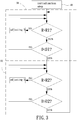
FIG. 3 is a flowchart of an embodiment according to the present invention, with a duty cycle value positively correlated with a motor rotational speed. -
FIG. 4 is a diagram showing hysteresis curves during speed switching of an embodiment according to the present invention. - As used herein, the term "flow rate" refers to the multiplication of a ventilation area of a fan and a speed of a wind flowing through the ventilation area, and its unit is m3/s, which can be appreciated by one having ordinary skill in the art.
- As used herein, the term "static pressure" refers to a pressure acting on a surface of an object by a gas, which is a pressure measured at a pressure measuring hole in a duct wall, with the pressure being perpendicular to the flowing direction, and its unit is Pa, which can be appreciated by one having ordinary skill in the art.
- As used herein, the term "equal rotational speed" refers to two rotational speeds having a difference within a tolerable error range, which can be appreciated by one having ordinary skill in the art.
-
FIG. 1 shows a block diagram of a method for controlling a rotational speed of a fan F of an embodiment according to the present invention. The fan F includes acontrol unit 1, amotor 2, and animpeller 3. Thecontrol unit 1 can be a micro controller (MCU). Thecontrol unit 1 can include a driving circuit electrically connected to themotor 2. Thecontrol unit 1 sends a pulse width modulation (PWM) driving signal to drive themotor 2 to rotate. The PWM driving signal includes an adjustable duty cycle value D. Themotor 2 can drive theimpeller 3 to rotate at a motor rotational speed R (which is identical to the rotational speed of theimpeller 3 and will not be redundantly described hereinafter). Themotor 2 includes aspeed detection unit 21 electrically connected to thecontrol unit 1. Thespeed detection unit 21 detects the motor rotational speed R and transmits a speed signal to thecontrol unit 1. Thespeed detection unit 21 can be a Hall sensor. - In this embodiment, the
control unit 1 and thespeed detection unit 21 can be integrated in a printed circuit board (PCB). The printed circuit board can be mounted in the fan F or themotor 2 to simplify the hardware, which is advantageous to reduction of the manufacturing costs. - The
control unit 1 can use parameters that are pre-stored to control the motor rotational speed R, such as a plurality of fan characteristic curves (static pressure-flow rate curve; namely, P-Q curve) respectively representing a plurality of different duty cycle values D, the relation between different duty cycle values D under a static pressure status and the motor rotational speed R, preset target duty cycle values, and preset target rotational speeds. The above parameters are obtained from experimental analyses of the power of themotor 2 and the fan components and can be used to control the motor rotational speed R to make the system approach a set target value. -
FIG. 2 is a diagram illustrating application of an embodiment according to the present invention. The fan F can be an air exchange fan and includes a plurality of air inlets I and an air outlet O. The plurality of air inlets I is respectively connected to a plurality of air ducts T which, in turn, is respectively connected to a plurality of open/closed spaces. A gate G is provided between each of the plurality of open/closed spaces and one of the plurality of air ducts T. The open/closed spaces requiring air exchange can be selected by opening and closing the plurality of gates G. As a result, different static pressures can be formed to influence the flow rate and the rotational speed of the fan F (air exchange fan) in operation. In this embodiment, the number of the plurality of air inlets I is at least three to perform two-stage constant speed control. However, the present invention is not limited in this regard. - With reference to
FIGS. 1 and3 , a method for controlling the rotational speed of the fan F according to the present invention includes an initialization step S0, a first constant speed step S1, and a second constant speed step S2. In the initialization step S0 thecontrol unit 1 sends out a PWM driving signal to start themotor 2. The PWM driving signal includes an initial duty cycle value D. Themotor 2 drives theimpeller 3 to rotate at an initial rotational speed. Thespeed detection unit 21 detects the motor rotational speed R and transmits it to thecontrol unit 1. In this embodiment, the duty cycle value D can be, but not limited to, 100%, and the initial rotational speed can be, but not limited to, 1600 rpm (revolutions per minute). - In the first constant speed step S1 the
control unit 1 is used to compare the currently detected motor rotational speed R with a first target rotational speed R1 that is pre-stored in thecontrol unit 1. When the motor rotational speed R is different from the first target rotational speed R1, the duty cycle value D outputted by thecontrol unit 1 is changed to make the motor rotational speed R approach the first target rotational speed R1. The procedure of comparing the motor rotational speed R and adjusting the duty cycle value D is repeated until the motor rotational speed R is equal to the first target rotational speed R1. Then, it is determined whether the current duty cycle value D and a first target duty cycle value D1 that is pre-stored in thecontrol unit 1 satisfy a first relational expression. If the duty cycle value D and the first target duty cycle value D1 do not satisfy the first relational expression, the first constant speed step S1 is repeated, such that the motor rotational speed R remains at the preset first target rotational speed R1. If the duty cycle value D and the first target duty cycle value D1 satisfy the first relational expression, the second constant speed step S2 is performed. In this embodiment, the first target rotational speed R1 can be, but not limited to, 1300 rpm, and the first target duty cycle value D1 can be, but not limited to, 70%. Furthermore, the duty cycle value D is positively correlated with the motor rotational speed R, such that the first relational expression is D<D1. However, the present invention is not limited in this regard. - With reference to
FIGS. 1-3 , specifically, since the fan F according to the present invention is connected via the plurality of air ducts T to the plurality of open/closed spaces for air exchange, the rotational speed of the fan F could be increased or reduced while opening or closing the plurality of gates G of the plurality of air ducts T. Thus, in this embodiment, when a portion of the plurality of gates G is opened or closed, the rotational speed of the fan F will vary due to a change in the system static pressure. At this time, thecontrol unit 1 must stabilize the motor rotational speed R through adjustment of the duty cycle value D to provide a stable flow rate. Furthermore, in this embodiment, when most of the plurality of gates G are closed, the fan F may only need to receive a PWM driving signal with a duty cycle value D smaller than the first target duty cycle value D1 (e.g., a PWM driving signal with a duty cycle value of 65%) to maintain rotation at the first target rotational speed R1. At this time, thecontrol unit 1 identifies that the operation should switch to the second constant speed step S2 to operate at a low rotational speed for avoiding a waste of energy. - In the second constant speed step S2, the
control unit 1 compares the currently detected motor rotational speed R with a second target rotational speed R2 that is pre-stored in thecontrol unit 1. When the motor rotational speed R is different from the second target rotational speed R2, the duty cycle value D outputted by thecontrol unit 1 is changed to make the motor rotational speed R approach the second target rotational speed R2. The procedure of comparing the motor rotational speed R and adjusting the duty cycle value D is repeated until the motor rotational speed R is equal to the second target rotational speed R2. Then, the current duty cycle value D and a second target duty cycle value D2 are compared. If the duty cycle value D and the second target duty cycle value D2 do not satisfy a second relational expression, the second constant speed step S2 is repeated. If the duty cycle value D and the second target duty cycle value D2 satisfy the second relational expression, the first constant speed step S1 is performed. In this embodiment, the second target rotational speed R2 can be, but not limited to, 1100 rpm, and the second target duty cycle value D2 can be, but not limited to, 50%. Furthermore, the duty cycle value D is positively correlated with the motor rotational speed R, such that the second relational expression is D>D2. However, the present invention is not limited in this regard. - Specifically, when most of the plurality of gates G is opened, the fan F may need to receive a PWM driving signal with a duty cycle value D larger than the second target duty cycle value D2 (e.g., a PWM driving signal with a duty cycle value of 55%) to maintain rotation at the second target rotational speed R2. At this time, the
control unit 1 identifies that the operation should switch to the first constant speed step S1 to operate at a high rotational speed for fulfilling the air exchange demand. - In the above embodiment, the duty cycle value D is positively correlated with the motor rotational speed R. Thus, the first relational expression must be satisfied by the duty cycle value D and the first target duty cycle value D1 is D<D1, the second relational expression must be satisfied by the duty cycle value D and the second target duty cycle value D2 is D>D2, and D1>D2 in this embodiment. In another embodiment, the duty cycle value D is negatively correlated with the motor rotational speed R. Thus, the first relational expression must be satisfied by the duty cycle value D and the first target duty cycle value D1 is D>D1, the second relational expression must be satisfied by the first target duty cycle value D1 and the second target duty cycle value D2 is D<D2, and D1<D2 in this embodiment.
- In another embodiment, the method for controlling the rotational speed of the fan F according to the present invention can further include a third constant speed step to maintain the fan F at a third target rotational speed R3 between the first target rotational speed R1 and the second target rotational speed R2. Furthermore, a third target duty cycle value D3 is used to identify whether to switch the motor rotational speed R. Accordingly, a fourth constant speed step and a fifth constant speed step can be added to maintain the fan F at a fourth target rotational speed or a fifth target rotational speed, and suitable ranges can be set according to the corresponding duty cycle values. However, the present invention is not limited in this regard.
-
FIG. 4 shows hysteresis curves during speed switching in a method for controlling a rotational speed of a fan F of an embodiment according to the present invention. The first constant speed step S1 corresponds to the 1300 rpm constant speed section of the fan characteristic curve, and the second constant speed step S2 corresponds to the 1100 rpm constant speed section of the fan characteristic curve. When the method proceeds from the first constant speed step S1 to the second constant speed step S2, a first hysteresis curve H1 is based. When the method proceeds from the second constant speed step S2 to the first constant speed step S1, a second hysteresis curve H2 is based. The setting of the first hysteresis curve H1 and the second hysteresis curve H2 can avoid excessively frequent switching of the motor rotational speed R within a short period of time (which would result in damage to themotor 2 or unstable air exchange) when the duty cycle value D of thecontrol unit 1 approaches the first target duty cycle value D1 or the second target duty cycle value D2. - In view of the foregoing, the method for controlling the rotational speed of the fan F according to the present invention does not need to refer to the operating current of the motor for algorithm. Instead, the duty cycle values D for switching the rotational speed are obtained from previously conducted experiments. Furthermore, the motor rotational speed R is compared and the duty cycle value D is adjusted, such that the fan F maintains at a constant speed no matter whether the static pressure of the environment changes or not, providing a stable air exchange for the open/closed spaces which are opened by the gates G.
Claims (15)
- A method for controlling a rotational speed of a fan (F), comprising:an initialization step (S0) including using a control unit (1) to start a motor (2) of the fan (F) according to an initial duty cycle value (D); characterised by a first constant speed step (S1) including using the control unit (1) to compare a motor rotational speed (R) with a first target rotational speed (R1), wherein the duty cycle value (D) outputted by the control unit (1) is changed to make the motor rotational speed (R) equal to the first target rotational speed (R1) when the motor rotational speed (R) is different from the first target rotational speed (R1), wherein when the motor rotational speed (R) is equal to the first target rotational speed (R1), it is determined whether the duty cycle value (D) and a first target duty cycle value (D1) satisfy a first relational expression, if not, the first constant speed step (S1) is repeated; anda second constant speed step (S2): wherein when the duty cycle value (D) and the first target duty cycle value (D1) satisfy the first relational expression in the first constant speed step (S1), the control unit (1) compares the motor rotational speed (R) with a second target rotational speed (R2), wherein the duty cycle value (D) outputted by the control unit (1) is changed to make the motor rotational speed (R) equal to the second target rotational speed (R2) when the motor rotational speed (R) is different from the second target rotational speed (R2), wherein when the motor rotational speed (R) is equal to the second target rotational speed (R2), it is determined whether the duty cycle value (D) and a second target duty cycle value (D2) satisfy a second relational expression, if not, the second constant speed step (S2) is repeated, and if so, the first constant speed step (S1) is performed.
- The method for controlling the rotational speed of the fan (F) as claimed in claim 1, characterized in that the duty cycle value (D) is positively correlated with the motor rotational speed (R), wherein the first relational expression is that the duty cycle value (D) is smaller than the first target duty cycle value (D1), wherein the second relational expression is that the duty cycle value (D) is larger than the second target duty cycle value (D2), and wherein the first target duty cycle value (D1) is larger than the second target duty cycle value (D2).
- The method for controlling the rotational speed of the fan (F) as claimed in claim 1, characterized in that the duty cycle value (D) is negatively correlated with the motor rotational speed (R), wherein the first relational expression is that the duty cycle value (D) is larger than the first target duty cycle value (D1), wherein the second relational expression is that the duty cycle value (D) is smaller than the second target duty cycle value (D2), and wherein the first target duty cycle value (D1) is smaller than the second target duty cycle value (D2).
- The method for controlling the rotational speed of the fan (F) as claimed in claim 1, characterized in that the first target rotational speed (R1), the second target rotational speed (R2), the first target duty cycle value (D1), the second target duty cycle value (D2), the first relational expression, and the second relational expression are stored in the control unit (1).
- The method for controlling the rotational speed of the fan (F) as claimed in claim 1, characterized in that the control unit (1) stores a plurality of fan characteristic curves respectively representing a plurality of different duty cycle values.
- The method for controlling the rotational speed of the fan (F) as claimed in claim 1, characterized in that the method proceeds from the first constant speed step (S1) to the second constant speed step (S2) according to a first hysteresis curve (H1), and wherein the method proceeds from the second constant speed step (S2) to the first constant speed step (S1) according to a second hysteresis curve (H2).
- A fan (F) comprising an impeller (3), a motor (2) for driving the impeller (3) to rotate at a motor rotational speed (R), and a control unit (1) electrically connected to the motor (2), wherein the control unit (1) outputs a driving signal with a duty cycle value (D) to drive the motor (2) to rotate at the motor rotational speed (R), characterised in that the control unit (1) is adapted to execute a first constant speed step (S1) including: comparing the motor rotational speed (R) with a first target rotational speed (R1), wherein the duty cycle value (D) outputted by the control unit (1) is changed to make the motor rotational speed (R) equal to the first target rotational speed (R1) when the motor rotational speed (R) is different from the first target rotational speed (R1), wherein when the motor rotational speed (R) is equal to the first target rotational speed (R1), it is determined whether the duty cycle value (D) and a first target duty cycle value (D1) satisfy a first relational expression, if not, the first constant speed step (S1) is repeated, if yes, the control unit (1) executes a second constant speed step (S2), in the second constant speed step (S2), the control unit (1) compares the motor rotational speed (R) with a second target rotational speed (R2), wherein the duty cycle value (D) outputted by the control unit (1) is changed to make the motor rotational speed (R) equal to the second target rotational speed (R2) when the motor rotational speed (R) is different from the second target rotational speed (R2), wherein when the motor rotational speed (R) is equal to the second target rotational speed (R2), it is determined whether the duty cycle value (D) and a second target duty cycle value (D2) satisfy a second relational expression, if not, the second constant speed step (S2) is repeated by the control unit (1), and if so, the first constant speed step (S1) is performed by the control unit (1).
- The fan (F) as claimed in claim 7, characterized in that the fan (F) is an air exchange fan including a plurality of air inlets (I) and an air outlet (O).
- The fan (F) as claimed in claim 8, characterized in that the plurality of air inlets (I) includes three air inlets (I).
- The fan (F) as claimed in claim 7, characterized in that the first target rotational speed (R1), the second target rotational speed (R2), and the target duty cycle value (D1, D2) are stored in the control unit (1), wherein the motor (2) changes from the first target rotational speed (R1) to the second target rotational speed (R2) according to a first hysteresis curve (HI), and wherein the motor (2) changes from the second target rotational speed (R2) to the first target rotational speed (R1) according to a second hysteresis curve (H2).
- The fan (F) as claimed in claim 7, characterized in that the control unit (1) stores a plurality of fan characteristic curves respectively representing a plurality of different duty cycle values.
- The fan (F) as claimed in claim 7, characterized in that the control unit (1) includes a driving circuit, and wherein the driving circuit is electrically connected to the motor (2) and is configured to drive the motor (2).
- The fan (F) as claimed in claim 7, characterized in that the motor (2) includes a speed detection unit (21) electrically connected to the control unit (1).
- The fan (F) as claimed in claim 13, characterized in that the control unit (1) and the speed detection unit (21) are integrated on a circuit board, and wherein the circuit board is mounted in the fan (F) or the motor (2).
- The fan (F) as claimed in claim 13, characterized in that the speed detection unit (21) is a Hall sensor.
Applications Claiming Priority (1)
| Application Number | Priority Date | Filing Date | Title |
|---|---|---|---|
| TW106123486A TWI629416B (en) | 2017-07-13 | 2017-07-13 | Fan and speed control method thereof |
Publications (2)
| Publication Number | Publication Date |
|---|---|
| EP3435537A1 EP3435537A1 (en) | 2019-01-30 |
| EP3435537B1 true EP3435537B1 (en) | 2020-11-04 |
Family
ID=62715956
Family Applications (1)
| Application Number | Title | Priority Date | Filing Date |
|---|---|---|---|
| EP18178858.9A Active EP3435537B1 (en) | 2017-07-13 | 2018-06-20 | Fan and rotational speed control method thereof |
Country Status (3)
| Country | Link |
|---|---|
| EP (1) | EP3435537B1 (en) |
| CN (1) | CN109253100B (en) |
| TW (1) | TWI629416B (en) |
Family Cites Families (11)
| Publication number | Priority date | Publication date | Assignee | Title |
|---|---|---|---|---|
| JP4658376B2 (en) * | 2001-05-17 | 2011-03-23 | 株式会社ミツバ | Actuator speed control method |
| TWI292654B (en) * | 2005-04-22 | 2008-01-11 | Delta Electronics Inc | Fan control device and method |
| JP5203768B2 (en) * | 2008-03-28 | 2013-06-05 | アズビル株式会社 | Ventilation system and method for controlling ventilation system |
| CN101594104B (en) * | 2008-05-28 | 2012-07-04 | 台达电子工业股份有限公司 | Motor control device and method thereof |
| US8198843B2 (en) * | 2008-06-17 | 2012-06-12 | Asmo Co., Ltd. | Motor control apparatus and motor control method |
| JP5651301B2 (en) * | 2009-01-22 | 2015-01-07 | セミコンダクター・コンポーネンツ・インダストリーズ・リミテッド・ライアビリティ・カンパニー | Motor drive circuit |
| JP5731753B2 (en) * | 2009-02-17 | 2015-06-10 | ローム株式会社 | Motor drive circuit, drive method, and cooling device |
| TWM372041U (en) * | 2009-06-23 | 2010-01-01 | Sunonwealth Electr Mach Ind Co | Motor with monitoring module for rotating speed |
| TW201135158A (en) * | 2010-04-02 | 2011-10-16 | Young-Chun Jeung | Constant airflow control of a ventilation system |
| CN104807140A (en) * | 2015-04-27 | 2015-07-29 | 广东美的暖通设备有限公司 | Method and system for detecting dust retention and air conditioner adopting method |
| TWI565218B (en) * | 2015-06-05 | 2017-01-01 | 茂達電子股份有限公司 | Motor speed curve control circuit and moter thereof |
-
2017
- 2017-07-13 TW TW106123486A patent/TWI629416B/en active
- 2017-07-21 CN CN201710601255.7A patent/CN109253100B/en active Active
-
2018
- 2018-06-20 EP EP18178858.9A patent/EP3435537B1/en active Active
Non-Patent Citations (1)
| Title |
|---|
| None * |
Also Published As
| Publication number | Publication date |
|---|---|
| CN109253100A (en) | 2019-01-22 |
| CN109253100B (en) | 2020-12-04 |
| TWI629416B (en) | 2018-07-11 |
| EP3435537A1 (en) | 2019-01-30 |
| TW201908603A (en) | 2019-03-01 |
Similar Documents
| Publication | Publication Date | Title |
|---|---|---|
| US7138781B2 (en) | Adaptive controller for PC cooling fans | |
| US8251671B2 (en) | Apparatus for controlling an air distribution system | |
| KR100940021B1 (en) | Ventilating device | |
| JP4687730B2 (en) | Blower and electric device equipped with the same | |
| US20070124574A1 (en) | Ramp rate closed-loop control (RRCC) for PC cooling fans | |
| EP2647515A1 (en) | Grille shutter device at a front portion of a vehicle | |
| KR101359529B1 (en) | Power saving airflow system for ehgine room and control method thereof | |
| WO2010120429A2 (en) | Constant airflow control of a ventilation system | |
| JP6109545B2 (en) | Air conditioner | |
| JP2005300089A (en) | Ventilator with air quantity correction function | |
| JP2009124776A (en) | Brushless DC motor drive device and ventilation blower equipped with the drive device | |
| US20230272799A1 (en) | Method and fan system for determination of a current operating point of a fan unit | |
| KR20110113900A (en) | Constant air flow ventilation control system | |
| EP3435537A1 (en) | Fan and rotational speed control method thereof | |
| KR20100109878A (en) | Calibration of the Motor for Constant Airflow Control | |
| KR101103018B1 (en) | Constant air flow control of the ventilation system | |
| JP4197101B2 (en) | Fan motor and ventilator equipped with the same | |
| JP5167657B2 (en) | Brushless DC motor drive device and ventilation blower equipped with the drive device | |
| CN204591750U (en) | The real-time measuring and adjustation device of a kind of blower wheel air gap | |
| US8482235B2 (en) | Fan arrangement in which the consumed electric power is influenced | |
| KR100717345B1 (en) | Air conditioner | |
| JPH08219535A (en) | VAV type air conditioning system | |
| JP5463131B2 (en) | Ventilation blower | |
| JP5061625B2 (en) | Ventilation equipment | |
| JP2606458B2 (en) | Air flow control device for air conditioner |
Legal Events
| Date | Code | Title | Description |
|---|---|---|---|
| PUAI | Public reference made under article 153(3) epc to a published international application that has entered the european phase |
Free format text: ORIGINAL CODE: 0009012 |
|
| STAA | Information on the status of an ep patent application or granted ep patent |
Free format text: STATUS: THE APPLICATION HAS BEEN PUBLISHED |
|
| AK | Designated contracting states |
Kind code of ref document: A1 Designated state(s): AL AT BE BG CH CY CZ DE DK EE ES FI FR GB GR HR HU IE IS IT LI LT LU LV MC MK MT NL NO PL PT RO RS SE SI SK SM TR |
|
| AX | Request for extension of the european patent |
Extension state: BA ME |
|
| STAA | Information on the status of an ep patent application or granted ep patent |
Free format text: STATUS: REQUEST FOR EXAMINATION WAS MADE |
|
| 17P | Request for examination filed |
Effective date: 20190429 |
|
| RBV | Designated contracting states (corrected) |
Designated state(s): AL AT BE BG CH CY CZ DE DK EE ES FI FR GB GR HR HU IE IS IT LI LT LU LV MC MK MT NL NO PL PT RO RS SE SI SK SM TR |
|
| STAA | Information on the status of an ep patent application or granted ep patent |
Free format text: STATUS: EXAMINATION IS IN PROGRESS |
|
| 17Q | First examination report despatched |
Effective date: 20191212 |
|
| GRAP | Despatch of communication of intention to grant a patent |
Free format text: ORIGINAL CODE: EPIDOSNIGR1 |
|
| STAA | Information on the status of an ep patent application or granted ep patent |
Free format text: STATUS: GRANT OF PATENT IS INTENDED |
|
| INTG | Intention to grant announced |
Effective date: 20200623 |
|
| RAP1 | Party data changed (applicant data changed or rights of an application transferred) |
Owner name: SUNONWEALTH ELECTRIC MACHINE INDUSTRY CO., LTD. |
|
| GRAS | Grant fee paid |
Free format text: ORIGINAL CODE: EPIDOSNIGR3 |
|
| GRAA | (expected) grant |
Free format text: ORIGINAL CODE: 0009210 |
|
| STAA | Information on the status of an ep patent application or granted ep patent |
Free format text: STATUS: THE PATENT HAS BEEN GRANTED |
|
| RIN1 | Information on inventor provided before grant (corrected) |
Inventor name: HORNG, ALEX Inventor name: CHIU, CHIH-HSIANG |
|
| AK | Designated contracting states |
Kind code of ref document: B1 Designated state(s): AL AT BE BG CH CY CZ DE DK EE ES FI FR GB GR HR HU IE IS IT LI LT LU LV MC MK MT NL NO PL PT RO RS SE SI SK SM TR |
|
| REG | Reference to a national code |
Ref country code: GB Ref legal event code: FG4D |
|
| REG | Reference to a national code |
Ref country code: CH Ref legal event code: EP |
|
| REG | Reference to a national code |
Ref country code: AT Ref legal event code: REF Ref document number: 1332120 Country of ref document: AT Kind code of ref document: T Effective date: 20201115 |
|
| REG | Reference to a national code |
Ref country code: IE Ref legal event code: FG4D |
|
| REG | Reference to a national code |
Ref country code: DE Ref legal event code: R096 Ref document number: 602018009321 Country of ref document: DE |
|
| REG | Reference to a national code |
Ref country code: NL Ref legal event code: MP Effective date: 20201104 |
|
| REG | Reference to a national code |
Ref country code: AT Ref legal event code: MK05 Ref document number: 1332120 Country of ref document: AT Kind code of ref document: T Effective date: 20201104 |
|
| PG25 | Lapsed in a contracting state [announced via postgrant information from national office to epo] |
Ref country code: NO Free format text: LAPSE BECAUSE OF FAILURE TO SUBMIT A TRANSLATION OF THE DESCRIPTION OR TO PAY THE FEE WITHIN THE PRESCRIBED TIME-LIMIT Effective date: 20210204 Ref country code: GR Free format text: LAPSE BECAUSE OF FAILURE TO SUBMIT A TRANSLATION OF THE DESCRIPTION OR TO PAY THE FEE WITHIN THE PRESCRIBED TIME-LIMIT Effective date: 20210205 Ref country code: RS Free format text: LAPSE BECAUSE OF FAILURE TO SUBMIT A TRANSLATION OF THE DESCRIPTION OR TO PAY THE FEE WITHIN THE PRESCRIBED TIME-LIMIT Effective date: 20201104 Ref country code: PT Free format text: LAPSE BECAUSE OF FAILURE TO SUBMIT A TRANSLATION OF THE DESCRIPTION OR TO PAY THE FEE WITHIN THE PRESCRIBED TIME-LIMIT Effective date: 20210304 Ref country code: FI Free format text: LAPSE BECAUSE OF FAILURE TO SUBMIT A TRANSLATION OF THE DESCRIPTION OR TO PAY THE FEE WITHIN THE PRESCRIBED TIME-LIMIT Effective date: 20201104 |
|
| PG25 | Lapsed in a contracting state [announced via postgrant information from national office to epo] |
Ref country code: BG Free format text: LAPSE BECAUSE OF FAILURE TO SUBMIT A TRANSLATION OF THE DESCRIPTION OR TO PAY THE FEE WITHIN THE PRESCRIBED TIME-LIMIT Effective date: 20210204 Ref country code: LV Free format text: LAPSE BECAUSE OF FAILURE TO SUBMIT A TRANSLATION OF THE DESCRIPTION OR TO PAY THE FEE WITHIN THE PRESCRIBED TIME-LIMIT Effective date: 20201104 Ref country code: IS Free format text: LAPSE BECAUSE OF FAILURE TO SUBMIT A TRANSLATION OF THE DESCRIPTION OR TO PAY THE FEE WITHIN THE PRESCRIBED TIME-LIMIT Effective date: 20210304 Ref country code: PL Free format text: LAPSE BECAUSE OF FAILURE TO SUBMIT A TRANSLATION OF THE DESCRIPTION OR TO PAY THE FEE WITHIN THE PRESCRIBED TIME-LIMIT Effective date: 20201104 Ref country code: SE Free format text: LAPSE BECAUSE OF FAILURE TO SUBMIT A TRANSLATION OF THE DESCRIPTION OR TO PAY THE FEE WITHIN THE PRESCRIBED TIME-LIMIT Effective date: 20201104 Ref country code: ES Free format text: LAPSE BECAUSE OF FAILURE TO SUBMIT A TRANSLATION OF THE DESCRIPTION OR TO PAY THE FEE WITHIN THE PRESCRIBED TIME-LIMIT Effective date: 20201104 Ref country code: AT Free format text: LAPSE BECAUSE OF FAILURE TO SUBMIT A TRANSLATION OF THE DESCRIPTION OR TO PAY THE FEE WITHIN THE PRESCRIBED TIME-LIMIT Effective date: 20201104 |
|
| REG | Reference to a national code |
Ref country code: LT Ref legal event code: MG9D |
|
| PG25 | Lapsed in a contracting state [announced via postgrant information from national office to epo] |
Ref country code: HR Free format text: LAPSE BECAUSE OF FAILURE TO SUBMIT A TRANSLATION OF THE DESCRIPTION OR TO PAY THE FEE WITHIN THE PRESCRIBED TIME-LIMIT Effective date: 20201104 |
|
| PG25 | Lapsed in a contracting state [announced via postgrant information from national office to epo] |
Ref country code: EE Free format text: LAPSE BECAUSE OF FAILURE TO SUBMIT A TRANSLATION OF THE DESCRIPTION OR TO PAY THE FEE WITHIN THE PRESCRIBED TIME-LIMIT Effective date: 20201104 Ref country code: CZ Free format text: LAPSE BECAUSE OF FAILURE TO SUBMIT A TRANSLATION OF THE DESCRIPTION OR TO PAY THE FEE WITHIN THE PRESCRIBED TIME-LIMIT Effective date: 20201104 Ref country code: SM Free format text: LAPSE BECAUSE OF FAILURE TO SUBMIT A TRANSLATION OF THE DESCRIPTION OR TO PAY THE FEE WITHIN THE PRESCRIBED TIME-LIMIT Effective date: 20201104 Ref country code: RO Free format text: LAPSE BECAUSE OF FAILURE TO SUBMIT A TRANSLATION OF THE DESCRIPTION OR TO PAY THE FEE WITHIN THE PRESCRIBED TIME-LIMIT Effective date: 20201104 Ref country code: SK Free format text: LAPSE BECAUSE OF FAILURE TO SUBMIT A TRANSLATION OF THE DESCRIPTION OR TO PAY THE FEE WITHIN THE PRESCRIBED TIME-LIMIT Effective date: 20201104 Ref country code: LT Free format text: LAPSE BECAUSE OF FAILURE TO SUBMIT A TRANSLATION OF THE DESCRIPTION OR TO PAY THE FEE WITHIN THE PRESCRIBED TIME-LIMIT Effective date: 20201104 |
|
| REG | Reference to a national code |
Ref country code: DE Ref legal event code: R097 Ref document number: 602018009321 Country of ref document: DE |
|
| PG25 | Lapsed in a contracting state [announced via postgrant information from national office to epo] |
Ref country code: DK Free format text: LAPSE BECAUSE OF FAILURE TO SUBMIT A TRANSLATION OF THE DESCRIPTION OR TO PAY THE FEE WITHIN THE PRESCRIBED TIME-LIMIT Effective date: 20201104 |
|
| PLBE | No opposition filed within time limit |
Free format text: ORIGINAL CODE: 0009261 |
|
| STAA | Information on the status of an ep patent application or granted ep patent |
Free format text: STATUS: NO OPPOSITION FILED WITHIN TIME LIMIT |
|
| 26N | No opposition filed |
Effective date: 20210805 |
|
| PG25 | Lapsed in a contracting state [announced via postgrant information from national office to epo] |
Ref country code: IT Free format text: LAPSE BECAUSE OF FAILURE TO SUBMIT A TRANSLATION OF THE DESCRIPTION OR TO PAY THE FEE WITHIN THE PRESCRIBED TIME-LIMIT Effective date: 20201104 Ref country code: NL Free format text: LAPSE BECAUSE OF FAILURE TO SUBMIT A TRANSLATION OF THE DESCRIPTION OR TO PAY THE FEE WITHIN THE PRESCRIBED TIME-LIMIT Effective date: 20201104 Ref country code: AL Free format text: LAPSE BECAUSE OF FAILURE TO SUBMIT A TRANSLATION OF THE DESCRIPTION OR TO PAY THE FEE WITHIN THE PRESCRIBED TIME-LIMIT Effective date: 20201104 |
|
| PG25 | Lapsed in a contracting state [announced via postgrant information from national office to epo] |
Ref country code: SI Free format text: LAPSE BECAUSE OF FAILURE TO SUBMIT A TRANSLATION OF THE DESCRIPTION OR TO PAY THE FEE WITHIN THE PRESCRIBED TIME-LIMIT Effective date: 20201104 |
|
| PG25 | Lapsed in a contracting state [announced via postgrant information from national office to epo] |
Ref country code: MC Free format text: LAPSE BECAUSE OF FAILURE TO SUBMIT A TRANSLATION OF THE DESCRIPTION OR TO PAY THE FEE WITHIN THE PRESCRIBED TIME-LIMIT Effective date: 20201104 |
|
| REG | Reference to a national code |
Ref country code: CH Ref legal event code: PL |
|
| REG | Reference to a national code |
Ref country code: BE Ref legal event code: MM Effective date: 20210630 |
|
| PG25 | Lapsed in a contracting state [announced via postgrant information from national office to epo] |
Ref country code: LU Free format text: LAPSE BECAUSE OF NON-PAYMENT OF DUE FEES Effective date: 20210620 |
|
| PG25 | Lapsed in a contracting state [announced via postgrant information from national office to epo] |
Ref country code: LI Free format text: LAPSE BECAUSE OF NON-PAYMENT OF DUE FEES Effective date: 20210630 Ref country code: IE Free format text: LAPSE BECAUSE OF NON-PAYMENT OF DUE FEES Effective date: 20210620 Ref country code: CH Free format text: LAPSE BECAUSE OF NON-PAYMENT OF DUE FEES Effective date: 20210630 |
|
| PG25 | Lapsed in a contracting state [announced via postgrant information from national office to epo] |
Ref country code: IS Free format text: LAPSE BECAUSE OF FAILURE TO SUBMIT A TRANSLATION OF THE DESCRIPTION OR TO PAY THE FEE WITHIN THE PRESCRIBED TIME-LIMIT Effective date: 20210304 |
|
| PG25 | Lapsed in a contracting state [announced via postgrant information from national office to epo] |
Ref country code: BE Free format text: LAPSE BECAUSE OF NON-PAYMENT OF DUE FEES Effective date: 20210630 |
|
| PG25 | Lapsed in a contracting state [announced via postgrant information from national office to epo] |
Ref country code: CY Free format text: LAPSE BECAUSE OF FAILURE TO SUBMIT A TRANSLATION OF THE DESCRIPTION OR TO PAY THE FEE WITHIN THE PRESCRIBED TIME-LIMIT Effective date: 20201104 |
|
| PG25 | Lapsed in a contracting state [announced via postgrant information from national office to epo] |
Ref country code: HU Free format text: LAPSE BECAUSE OF FAILURE TO SUBMIT A TRANSLATION OF THE DESCRIPTION OR TO PAY THE FEE WITHIN THE PRESCRIBED TIME-LIMIT; INVALID AB INITIO Effective date: 20180620 |
|
| PG25 | Lapsed in a contracting state [announced via postgrant information from national office to epo] |
Ref country code: MK Free format text: LAPSE BECAUSE OF FAILURE TO SUBMIT A TRANSLATION OF THE DESCRIPTION OR TO PAY THE FEE WITHIN THE PRESCRIBED TIME-LIMIT Effective date: 20201104 |
|
| PG25 | Lapsed in a contracting state [announced via postgrant information from national office to epo] |
Ref country code: TR Free format text: LAPSE BECAUSE OF FAILURE TO SUBMIT A TRANSLATION OF THE DESCRIPTION OR TO PAY THE FEE WITHIN THE PRESCRIBED TIME-LIMIT Effective date: 20201104 |
|
| PG25 | Lapsed in a contracting state [announced via postgrant information from national office to epo] |
Ref country code: MT Free format text: LAPSE BECAUSE OF FAILURE TO SUBMIT A TRANSLATION OF THE DESCRIPTION OR TO PAY THE FEE WITHIN THE PRESCRIBED TIME-LIMIT Effective date: 20201104 |
|
| PGFP | Annual fee paid to national office [announced via postgrant information from national office to epo] |
Ref country code: GB Payment date: 20260623 Year of fee payment: 9 |
|
| PGFP | Annual fee paid to national office [announced via postgrant information from national office to epo] |
Ref country code: DE Payment date: 20260420 Year of fee payment: 9 |
|
| PGFP | Annual fee paid to national office [announced via postgrant information from national office to epo] |
Ref country code: FR Payment date: 20260522 Year of fee payment: 9 |