EP3435354A1 - Vehicle control device - Google Patents
Vehicle control device Download PDFInfo
- Publication number
- EP3435354A1 EP3435354A1 EP17769661.4A EP17769661A EP3435354A1 EP 3435354 A1 EP3435354 A1 EP 3435354A1 EP 17769661 A EP17769661 A EP 17769661A EP 3435354 A1 EP3435354 A1 EP 3435354A1
- Authority
- EP
- European Patent Office
- Prior art keywords
- vehicle
- information
- space
- control device
- vicinity
- Prior art date
- Legal status (The legal status is an assumption and is not a legal conclusion. Google has not performed a legal analysis and makes no representation as to the accuracy of the status listed.)
- Granted
Links
Images


Classifications
-
- G—PHYSICS
- G08—SIGNALLING
- G08G—TRAFFIC CONTROL SYSTEMS
- G08G1/00—Traffic control systems for road vehicles
- G08G1/16—Anti-collision systems
- G08G1/161—Decentralised systems, e.g. inter-vehicle communication
-
- B—PERFORMING OPERATIONS; TRANSPORTING
- B60—VEHICLES IN GENERAL
- B60Q—ARRANGEMENT OF SIGNALLING OR LIGHTING DEVICES, THE MOUNTING OR SUPPORTING THEREOF OR CIRCUITS THEREFOR, FOR VEHICLES IN GENERAL
- B60Q1/00—Arrangement of optical signalling or lighting devices, the mounting or supporting thereof or circuits therefor
- B60Q1/26—Arrangement of optical signalling or lighting devices, the mounting or supporting thereof or circuits therefor the devices being primarily intended to indicate the vehicle, or parts thereof, or to give signals, to other traffic
- B60Q1/34—Arrangement of optical signalling or lighting devices, the mounting or supporting thereof or circuits therefor the devices being primarily intended to indicate the vehicle, or parts thereof, or to give signals, to other traffic for indicating change of drive direction
- B60Q1/346—Arrangement of optical signalling or lighting devices, the mounting or supporting thereof or circuits therefor the devices being primarily intended to indicate the vehicle, or parts thereof, or to give signals, to other traffic for indicating change of drive direction with automatic actuation
-
- B—PERFORMING OPERATIONS; TRANSPORTING
- B60—VEHICLES IN GENERAL
- B60R—VEHICLES, VEHICLE FITTINGS, OR VEHICLE PARTS, NOT OTHERWISE PROVIDED FOR
- B60R21/00—Arrangements or fittings on vehicles for protecting or preventing injuries to occupants or pedestrians in case of accidents or other traffic risks
-
- B—PERFORMING OPERATIONS; TRANSPORTING
- B60—VEHICLES IN GENERAL
- B60W—CONJOINT CONTROL OF VEHICLE SUB-UNITS OF DIFFERENT TYPE OR DIFFERENT FUNCTION; CONTROL SYSTEMS SPECIALLY ADAPTED FOR HYBRID VEHICLES; ROAD VEHICLE DRIVE CONTROL SYSTEMS FOR PURPOSES NOT RELATED TO THE CONTROL OF A PARTICULAR SUB-UNIT
- B60W30/00—Purposes of road vehicle drive control systems not related to the control of a particular sub-unit, e.g. of systems using conjoint control of vehicle sub-units
- B60W30/08—Active safety systems predicting or avoiding probable or impending collision or attempting to minimise its consequences
- B60W30/095—Predicting travel path or likelihood of collision
- B60W30/0956—Predicting travel path or likelihood of collision the prediction being responsive to traffic or environmental parameters
-
- B—PERFORMING OPERATIONS; TRANSPORTING
- B60—VEHICLES IN GENERAL
- B60W—CONJOINT CONTROL OF VEHICLE SUB-UNITS OF DIFFERENT TYPE OR DIFFERENT FUNCTION; CONTROL SYSTEMS SPECIALLY ADAPTED FOR HYBRID VEHICLES; ROAD VEHICLE DRIVE CONTROL SYSTEMS FOR PURPOSES NOT RELATED TO THE CONTROL OF A PARTICULAR SUB-UNIT
- B60W30/00—Purposes of road vehicle drive control systems not related to the control of a particular sub-unit, e.g. of systems using conjoint control of vehicle sub-units
- B60W30/14—Adaptive cruise control
- B60W30/16—Control of distance between vehicles, e.g. keeping a distance to preceding vehicle
-
- B—PERFORMING OPERATIONS; TRANSPORTING
- B60—VEHICLES IN GENERAL
- B60W—CONJOINT CONTROL OF VEHICLE SUB-UNITS OF DIFFERENT TYPE OR DIFFERENT FUNCTION; CONTROL SYSTEMS SPECIALLY ADAPTED FOR HYBRID VEHICLES; ROAD VEHICLE DRIVE CONTROL SYSTEMS FOR PURPOSES NOT RELATED TO THE CONTROL OF A PARTICULAR SUB-UNIT
- B60W30/00—Purposes of road vehicle drive control systems not related to the control of a particular sub-unit, e.g. of systems using conjoint control of vehicle sub-units
- B60W30/18—Propelling the vehicle
- B60W30/18009—Propelling the vehicle related to particular drive situations
- B60W30/18163—Lane change; Overtaking manoeuvres
-
- B—PERFORMING OPERATIONS; TRANSPORTING
- B60—VEHICLES IN GENERAL
- B60W—CONJOINT CONTROL OF VEHICLE SUB-UNITS OF DIFFERENT TYPE OR DIFFERENT FUNCTION; CONTROL SYSTEMS SPECIALLY ADAPTED FOR HYBRID VEHICLES; ROAD VEHICLE DRIVE CONTROL SYSTEMS FOR PURPOSES NOT RELATED TO THE CONTROL OF A PARTICULAR SUB-UNIT
- B60W40/00—Estimation or calculation of non-directly measurable driving parameters for road vehicle drive control systems not related to the control of a particular sub unit, e.g. by using mathematical models
- B60W40/02—Estimation or calculation of non-directly measurable driving parameters for road vehicle drive control systems not related to the control of a particular sub unit, e.g. by using mathematical models related to ambient conditions
- B60W40/04—Traffic conditions
-
- B—PERFORMING OPERATIONS; TRANSPORTING
- B60—VEHICLES IN GENERAL
- B60W—CONJOINT CONTROL OF VEHICLE SUB-UNITS OF DIFFERENT TYPE OR DIFFERENT FUNCTION; CONTROL SYSTEMS SPECIALLY ADAPTED FOR HYBRID VEHICLES; ROAD VEHICLE DRIVE CONTROL SYSTEMS FOR PURPOSES NOT RELATED TO THE CONTROL OF A PARTICULAR SUB-UNIT
- B60W60/00—Drive control systems specially adapted for autonomous road vehicles
- B60W60/001—Planning or execution of driving tasks
-
- G—PHYSICS
- G08—SIGNALLING
- G08G—TRAFFIC CONTROL SYSTEMS
- G08G1/00—Traffic control systems for road vehicles
- G08G1/16—Anti-collision systems
- G08G1/161—Decentralised systems, e.g. inter-vehicle communication
- G08G1/162—Decentralised systems, e.g. inter-vehicle communication event-triggered
-
- G—PHYSICS
- G08—SIGNALLING
- G08G—TRAFFIC CONTROL SYSTEMS
- G08G1/00—Traffic control systems for road vehicles
- G08G1/16—Anti-collision systems
- G08G1/161—Decentralised systems, e.g. inter-vehicle communication
- G08G1/163—Decentralised systems, e.g. inter-vehicle communication involving continuous checking
-
- G—PHYSICS
- G08—SIGNALLING
- G08G—TRAFFIC CONTROL SYSTEMS
- G08G1/00—Traffic control systems for road vehicles
- G08G1/16—Anti-collision systems
- G08G1/167—Driving aids for lane monitoring, lane changing, e.g. blind spot detection
-
- H—ELECTRICITY
- H04—ELECTRIC COMMUNICATION TECHNIQUE
- H04W—WIRELESS COMMUNICATION NETWORKS
- H04W4/00—Services specially adapted for wireless communication networks; Facilities therefor
- H04W4/30—Services specially adapted for particular environments, situations or purposes
- H04W4/40—Services specially adapted for particular environments, situations or purposes for vehicles, e.g. vehicle-to-pedestrians [V2P]
- H04W4/44—Services specially adapted for particular environments, situations or purposes for vehicles, e.g. vehicle-to-pedestrians [V2P] for communication between vehicles and infrastructures, e.g. vehicle-to-cloud [V2C] or vehicle-to-home [V2H]
-
- H—ELECTRICITY
- H04—ELECTRIC COMMUNICATION TECHNIQUE
- H04W—WIRELESS COMMUNICATION NETWORKS
- H04W4/00—Services specially adapted for wireless communication networks; Facilities therefor
- H04W4/30—Services specially adapted for particular environments, situations or purposes
- H04W4/40—Services specially adapted for particular environments, situations or purposes for vehicles, e.g. vehicle-to-pedestrians [V2P]
- H04W4/46—Services specially adapted for particular environments, situations or purposes for vehicles, e.g. vehicle-to-pedestrians [V2P] for vehicle-to-vehicle communication [V2V]
-
- B—PERFORMING OPERATIONS; TRANSPORTING
- B60—VEHICLES IN GENERAL
- B60W—CONJOINT CONTROL OF VEHICLE SUB-UNITS OF DIFFERENT TYPE OR DIFFERENT FUNCTION; CONTROL SYSTEMS SPECIALLY ADAPTED FOR HYBRID VEHICLES; ROAD VEHICLE DRIVE CONTROL SYSTEMS FOR PURPOSES NOT RELATED TO THE CONTROL OF A PARTICULAR SUB-UNIT
- B60W2552/00—Input parameters relating to infrastructure
- B60W2552/50—Barriers
-
- B—PERFORMING OPERATIONS; TRANSPORTING
- B60—VEHICLES IN GENERAL
- B60W—CONJOINT CONTROL OF VEHICLE SUB-UNITS OF DIFFERENT TYPE OR DIFFERENT FUNCTION; CONTROL SYSTEMS SPECIALLY ADAPTED FOR HYBRID VEHICLES; ROAD VEHICLE DRIVE CONTROL SYSTEMS FOR PURPOSES NOT RELATED TO THE CONTROL OF A PARTICULAR SUB-UNIT
- B60W2552/00—Input parameters relating to infrastructure
- B60W2552/53—Road markings, e.g. lane marker or crosswalk
-
- B—PERFORMING OPERATIONS; TRANSPORTING
- B60—VEHICLES IN GENERAL
- B60W—CONJOINT CONTROL OF VEHICLE SUB-UNITS OF DIFFERENT TYPE OR DIFFERENT FUNCTION; CONTROL SYSTEMS SPECIALLY ADAPTED FOR HYBRID VEHICLES; ROAD VEHICLE DRIVE CONTROL SYSTEMS FOR PURPOSES NOT RELATED TO THE CONTROL OF A PARTICULAR SUB-UNIT
- B60W2554/00—Input parameters relating to objects
- B60W2554/80—Spatial relation or speed relative to objects
- B60W2554/801—Lateral distance
Definitions
- the present invention relates to a vehicle control device for merging from a merging lane to a main lane by automatic driving.
- existing methods for acquiring external environment information related to the host vehicle include an acquisition method by communication and an acquisition method by a sensor mounted on the host vehicle (PTL 2).
- the method of acquiring external environment information by communication has an advantage that relatively high accuracy and reliability of information can be expected in terms of being objective information.
- This method has a disadvantage that information might not be acquired as a matter of course in a case where an object present in the external environment is not compatible with communication.
- the method of acquiring external environment information by a sensor has an advantage that information can be acquired irrespective of whether an object present in the vicinity is compatible with communication.
- This method has a disadvantage of causing a concern about accuracy or reliability of information because the information is obtained by the sensor mounted on the host vehicle and thus is not objective information.
- An object of the present invention to provide a vehicle control device that can take advantage of the above two methods to appropriately grasp the external environment while suppressing an excessive computation load.
- a vehicle control device comprises an other vehicle information acquisition unit that acquires information of another vehicle by communication; and an exterior recognition unit that carries out recognition of the exterior of a host vehicle by sensing.
- the exterior recognition unit senses an other vehicle vicinity space in the vicinity of the other vehicle on the basis of the information of the other vehicle acquired by the other vehicle information acquisition unit.
- FIG. 1 illustrates a block diagram of a vehicle control device.
- a vehicle control device 01 includes an other vehicle information acquisition unit 02 that performs communication (C2X) such as vehicle-to-vehicle communication (C2C) and road-to-vehicle communication (C2I), an exterior recognition unit 03 that acquires information situation of vehicles in the vicinity of the host vehicle and roads from various sensors such as a radar and a camera, a host vehicle vicinity information management unit 04 that integrates the information from the other vehicle information acquisition unit 02 and the information from the exterior recognition unit 03 to manage the situation of vehicles in the vicinity of the host vehicle and the roads; a host vehicle action recognition unit 05 that senses states of the host vehicle such as position, speed, acceleration, and a yaw rate, and a path generating unit 06 that determines a path of the host vehicle on the basis of information from the host vehicle vicinity information management unit 04 and the host vehicle action recognition unit 05.
- C2X vehicle-to-vehicle communication
- C2I road-to-veh
- the other vehicle information acquisition unit 02 acquires information of another vehicle by communication (C2X).
- the other vehicle information acquisition unit 02 acquires vicinity vehicle action information (information of other vehicles) such as position, speed, acceleration, and yaw rate by vehicle-to-vehicle communication (C2C). That is, vehicle information transmitted from the other vehicle is acquired by vehicle-to-vehicle communication.
- the other vehicle information acquisition unit 02 uses road-to-vehicle communication (C2I) to acquire information such as the position, speed, and acceleration of a vehicle traveling on a road (information of other vehicle) acquired on a roadside device by analyzing information from sensors such as radar and cameras. That is, the information of other vehicles transmitted from on-road equipment is acquired by road-to-vehicle communication.
- C2I road-to-vehicle communication
- the other vehicle information acquisition unit 02 acquires information of the other vehicle present in an other vehicle information sensing range A2 in 300m to 500m vicinity of the host vehicle, for example.
- Examples of the other vehicle include a vehicle traveling on a road merging into the road on which the host vehicle travels, and a vehicle traveling on an adjacent lane of the lane on which the host vehicle travels.
- the vehicle-to-vehicle communication and the road-to-vehicle communication are performed using a cooperative awareness message (CAM).
- the CAM is a message used mainly for safety system services of cooperative ITS, and is exchanged between ITS stations (ITS-S) to build and maintain mutual recognition and support cooperativeness in road networks.
- the CAM includes state information and attribute information of the source ITS-S, and includes different information depending on the type of ITS-S.
- the state information includes time, position, and operation state, while the attribute information includes data on dimensions, vehicle type, and role in the road traffic or the like.
- a receiving ITS-S can recognize existence of a source ITS-S and can acquire the type and the state of the source ITS-S by CAM reception.
- a CAM parameter includes a basic container, a vehicle ITS-S container, and a special vehicle container.
- the basic container describes the type of the source ITS-S and the latest geographical position of the source ITS-S as basic information of the source ITS-S.
- the vehicle ITS-S container includes high frequency containers and low frequency containers.
- the high frequency container describes dynamic state information of the vehicle ITS-S such as direction, speed and acceleration, while the low frequency container describes container divisions of special vehicles and external lights.
- the special container is a container for a vehicle ITS-S having a special role in the road traffic such as public transportation.
- the exterior recognition unit 03 recognizes the exterior of the host vehicle by sensing.
- the exterior recognition unit 03 is capable of acquiring the relative position and the state of vehicles, obstacles, road signs or the like in the vicinity of the host vehicle from sensors such as cameras and radars mounted on the host vehicle.
- the exterior recognition unit 03 can recognize an exterior recognition sensing range A1 in 70m to 100m vicinity of the host vehicle, for example.
- the exterior recognition unit 03 can sense the other vehicle and sense the other vehicle vicinity space in the vicinity of the other vehicle on the basis of the information of the other vehicle acquired by the other vehicle information acquisition unit 02.
- While the exterior recognition unit 30 also senses and confirms an object such as the other vehicle existence of which is already known by communication (C2X), priority is given to the sensing of the space in the vicinity of the object over the sensing of the object existence of which is already known by communication. Furthermore, intensive sensing is performed for the space in the vicinity of the object. More precise sensing is performed by for example, increasing the frequency of processing toward the vicinity of the object more than the object existence of which is already known by communication (C2X), or by changing the resource, etc.
- the host vehicle vicinity information management unit 04 integrates information from the other vehicle information acquisition unit 02 and information from the exterior recognition unit 03 and manages the integrated information as host vehicle vicinity information.
- the other vehicle information acquisition unit 02 can acquire information of vicinity vehicles and roads in the other vehicle information sensing range A2, which is a wider range than the exterior recognition sensing range A1 of the exterior recognition unit 03.
- the host vehicle vicinity information in the other vehicle information sensing range A2 is first acquired by the other vehicle information acquisition unit 02, and thereafter, the host vehicle vicinity information acquired by the other vehicle information acquisition unit 02 is matched against the information acquired by the exterior recognition unit 03 at a stage of entering the exterior recognition sensing range A1 of the exterior recognition unit 03.
- This configuration makes it possible to sense the host vehicle vicinity information with higher accuracy.
- With execution of prioritization of the objects as sensing targets of the exterior recognition unit 03 on the basis of information acquired by the other vehicle information acquisition unit 02, for example, the characteristics and position of the vehicle it is possible to more efficiently sense the host vehicle vicinity information.
- the host vehicle action recognition unit 05 can acquire information such as the yaw rate, the wheel speed, the steering angle, the acceleration, representing the action of the host vehicle respectively from a gyro sensor, a wheel speed sensor, a steering angle sensor, an acceleration sensor, for example.
- the path generating unit 06 performs sensing for a mergeable space on the main lane into which the host vehicle can merge (an entry space that allows the host vehicle to enter) on the basis of the information from the host vehicle vicinity information management unit 04 and the information from the host vehicle action recognition unit 05, and determines a path for entering the mergeable space. Then, in accordance with the determined path, the path generating unit 06 transmits a control signal and performs vehicle control of the host vehicle in the longitudinal direction such as accelerator and the brake, and in the lateral direction such as steering.
- the mergeable space is continuously sensed on the basis of the information from the host vehicle vicinity information management unit 04 and the host vehicle action recognition unit 05, and when there is a change in the mergeable space, the path is generated again.
- a host vehicle F01 is traveling on a merging lane Lb.
- a main lane La is outside the sensing range A1 of the exterior recognition unit 03, other vehicles on the main lane La and road conditions are sensed by the information from the other vehicle information acquisition unit 02.
- sensing of other vehicles by the exterior recognition unit 03 is not available.
- a target speed of the host vehicle F01 is set to accelerate the host vehicle F01 so as to fit in the traffic stream of other vehicles on the main lane La.
- the speed limit of the host vehicle F01 is set to the target speed to accelerate the host vehicle F01.
- the exterior recognition unit 03 performs sensing to examine whether there is a practically mergeable space on the main lane La. In a case where there is mergeable space as a result of the sensing, the vehicle is accelerated to the set speed continuously.
- a space F04 existing behind the vehicle F03 corresponds to the other mergeable space.
- the set speed of the host vehicle F01 is changed to enable merging into the other space F04.
- another mergeable space behind the space F04 and within the merging section is also searched for and listed as a candidate for a mergeable space.
- the space that would be available as a mergeable space provided that the succeeding vehicle F03 decelerates or changes the lane, existing from a side closer to the merging start point Ps toward the rear side, is listed as a candidate merging space.
- the candidate mergeable space on the main lane La gradually enters the sensing range A1 of an exterior recognition sensor.
- the exterior recognition unit 03 preferentially senses the candidate mergeable space F04 among the sensing range of the exterior recognition sensor and checks for the vehicles that could not be detected by vehicle-to-vehicle communication or road-to-vehicle communication, and for the other vehicles that were once present and sensed in the vicinity of the space F04 but might have their mergeable spaces changed due to acceleration and deceleration or lane change of the other vehicles. Thereafter, when it is confirmed that merging is continuously possible, the exterior recognition unit 03 determines a path for entering the mergeable space and performs vehicle control for the merging.
- the exterior recognition unit 03 senses and confirms the other vehicle existence of which is already known by communication (C2X)
- prioritized sensing is performed toward the other vehicle vicinity space such as the candidate space F04.
- the frequency and resources of detection processing are changed to achieve sensing for this space more intensive than for the other vehicles.
- the imaging speed and image processing accuracy are increased.
- the other vehicle information acquisition unit 02 may change the degree of intensiveness of sensing in accordance with which of the following pattern is used to acquire the information of the other vehicle: (1) vehicle-to-vehicle communication (C2C) alone; (2) both the vehicle-to-vehicle communication and the road-to-vehicle communication (C2C + C2I); and (3) the road-to-vehicle communication (C2I) alone.
- C2C vehicle-to-vehicle communication
- C2C + C2I both the vehicle-to-vehicle communication
- information has higher accuracy compared with the case using (3) road-to-vehicle communication (C2I) alone. Accordingly, it is allowable to perform the sensing for the other vehicles with less intensiveness than the case of (3) road-to-vehicle communication (C2I) alone and perform the sensing for the vicinity region other than the other vehicles with more intensiveness.
- Determination is made whether the information of the other vehicle on the main lane La has been acquired by vehicle-to-vehicle/road-to-vehicle communication (S101). In a case where the information has been acquired (YES in S101), the vehicle is accelerated to fit the speed of the other vehicle traveling on the main lane La (S102). In a case where the information has not been acquired (NO in S101), the vehicle is accelerated to conform to the speed limit of the main lane La (S109).
- a search is performed to a candidate mergeable space (S103), and the vehicle is accelerated to enable merging into the candidate mergeable space (S104), a lane-changing signal is issued by a blinker/vehicle-to-vehicle communication (S105), while sensing a candidate mergeable space by the exterior recognition unit 03 (S106).
- a candidate mergeable space for the host vehicle is detected on the basis of the information of other vehicles in the vicinity acquired by the vehicle-to-vehicle communication and the road-to-vehicle communication, and the candidate mergeable space is verified by the exterior recognition using a sensor.
- the lane change on the main lane can also be implemented with a control similar to the case of merging.
- An example of the specific control will be described below.
- the exterior recognition unit 03 senses an inter-other vehicle space between the plurality of other vehicles. For example, as illustrated in FIG.
- the information from the host vehicle vicinity information management unit 04 is used for sensing the other vehicles F02, F03, F04, and F05 and the road conditions on the passing lane La1.
- a lane changeable space inter-other vehicle space
- candidates are searched for in a direction from the other vehicle in a closer position within the sensing range A1 of the exterior recognition unit 03, immediately adjacent to the host vehicle, toward the other vehicle more distant within the sensing range A1 of the exterior recognition unit 03.
- the host vehicle is decelerated down to the speed that enables lane change to that space.
- the speed of the host vehicle F01 is adjusted so as to change the lane to the inter-other vehicle space F06.
- Preferential sensing is performed at a point where the inter-other vehicle space F06 as the lane changeable space as illustrated in FIG. 8 comes within the sensing range A1 of the exterior recognition unit 03.
- a path to enter the inter-other vehicle space F06 is determined and vehicle control for lane change is executed.
Landscapes
- Engineering & Computer Science (AREA)
- Physics & Mathematics (AREA)
- Mechanical Engineering (AREA)
- General Physics & Mathematics (AREA)
- Automation & Control Theory (AREA)
- Transportation (AREA)
- Computer Networks & Wireless Communication (AREA)
- Signal Processing (AREA)
- Mathematical Physics (AREA)
- Human Computer Interaction (AREA)
- Traffic Control Systems (AREA)
- Control Of Driving Devices And Active Controlling Of Vehicle (AREA)
Abstract
Description
- The present invention relates to a vehicle control device for merging from a merging lane to a main lane by automatic driving.
- There is a known traveling support device that sets an appropriate acceleration of a host vehicle on the basis of a traveling state of another vehicle on a main lane when merging from a merging lane to the main lane on a highway or the like (PTL 1).
- Meanwhile, existing methods for acquiring external environment information related to the host vehicle include an acquisition method by communication and an acquisition method by a sensor mounted on the host vehicle (PTL 2).
-
- PTL 1:
JP 2011-048456 A - PTL 2:
JP 2008-129804 A - In
PTL 1, however, in actually merging, there is a problem of grasping actions of vicinity vehicles and checking whether there is an available space for the host vehicle to safely merge, in addition to perform acceleration to an appropriate speed. - Each of the methods of PTL 2 includes the following advantages and disadvantages.
- For example, the method of acquiring external environment information by communication has an advantage that relatively high accuracy and reliability of information can be expected in terms of being objective information. This method, however, has a disadvantage that information might not be acquired as a matter of course in a case where an object present in the external environment is not compatible with communication.
- On the other hand, the method of acquiring external environment information by a sensor has an advantage that information can be acquired irrespective of whether an object present in the vicinity is compatible with communication. This method, however, has a disadvantage of causing a concern about accuracy or reliability of information because the information is obtained by the sensor mounted on the host vehicle and thus is not objective information. There is another disadvantage of an increase in the computation load in order to enhance sensing accuracy of the sensor.
- An object of the present invention to provide a vehicle control device that can take advantage of the above two methods to appropriately grasp the external environment while suppressing an excessive computation load.
- In order to solve the above problem, a vehicle control device according to the present invention comprises an other vehicle information acquisition unit that acquires information of another vehicle by communication; and an exterior recognition unit that carries out recognition of the exterior of a host vehicle by sensing. The exterior recognition unit senses an other vehicle vicinity space in the vicinity of the other vehicle on the basis of the information of the other vehicle acquired by the other vehicle information acquisition unit.
- According to the present invention, it is possible to accelerate to a necessary speed to support merging, further confirm safety, and perform vehicle control for merging.
- Further features related to the present invention will become apparent from the description of this description and the accompanying drawings. Problems, configurations, and effects other than in the above description will become apparent by the following embodiments.
-
- [
FIG. 1] FIG. 1 is a diagram illustrating a configuration example of an in-vehicle system using a vehicle control device according to the present invention. - [
FIG. 2] FIG. 2 is a diagram illustrating an example of a vehicle on a main lane, outside the exterior recognition range, according to the present invention. - [
FIG. 3] FIG. 3 is a diagram illustrating an example in which there is a vehicle to be an obstacle for merging in a mergeable space according to the present invention. - [
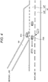
FIG. 4] FIG. 4 is a diagram illustrating an example of ensuring a mergeable space by deceleration or lane change of a succeeding vehicle on a main lane according to the present invention. - [
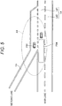
FIG. 5] FIG. 5 is a diagram illustrating an example of verifying a mergeable space by an exterior recognition unit according to the present invention. - [
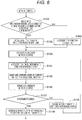
FIG. 6] FIG. 6 is a diagram illustrating an example of a control flowchart at the time of merging from a merging lane to a main lane according to the present invention. - [
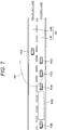
FIG. 7] FIG. 7 is a diagram illustrating an example of a vehicle and a road condition at the time of lane change by the exterior recognition unit according to the present invention. - [
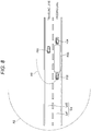
FIG. 8] FIG. 8 is a diagram illustrating an example in which the exterior recognition unit according to the present invention verifies a lane changeable space. - Embodiments of the present invention will be described below with reference to the accompanying drawings.
-
FIG. 1 illustrates a block diagram of a vehicle control device. Avehicle control device 01 includes an other vehicleinformation acquisition unit 02 that performs communication (C2X) such as vehicle-to-vehicle communication (C2C) and road-to-vehicle communication (C2I), anexterior recognition unit 03 that acquires information situation of vehicles in the vicinity of the host vehicle and roads from various sensors such as a radar and a camera, a host vehicle vicinityinformation management unit 04 that integrates the information from the other vehicleinformation acquisition unit 02 and the information from theexterior recognition unit 03 to manage the situation of vehicles in the vicinity of the host vehicle and the roads; a host vehicleaction recognition unit 05 that senses states of the host vehicle such as position, speed, acceleration, and a yaw rate, and apath generating unit 06 that determines a path of the host vehicle on the basis of information from the host vehicle vicinityinformation management unit 04 and the host vehicleaction recognition unit 05. - The other vehicle
information acquisition unit 02 acquires information of another vehicle by communication (C2X). The other vehicleinformation acquisition unit 02 acquires vicinity vehicle action information (information of other vehicles) such as position, speed, acceleration, and yaw rate by vehicle-to-vehicle communication (C2C). That is, vehicle information transmitted from the other vehicle is acquired by vehicle-to-vehicle communication. In addition, the other vehicleinformation acquisition unit 02 uses road-to-vehicle communication (C2I) to acquire information such as the position, speed, and acceleration of a vehicle traveling on a road (information of other vehicle) acquired on a roadside device by analyzing information from sensors such as radar and cameras. That is, the information of other vehicles transmitted from on-road equipment is acquired by road-to-vehicle communication. The other vehicleinformation acquisition unit 02 acquires information of the other vehicle present in an other vehicle information sensing range A2 in 300m to 500m vicinity of the host vehicle, for example. Examples of the other vehicle include a vehicle traveling on a road merging into the road on which the host vehicle travels, and a vehicle traveling on an adjacent lane of the lane on which the host vehicle travels. There are three patterns of communication (C2X) in the present Example as follows: (1) vehicle-to-vehicle communication (C2C) alone; (2) both vehicle-to-vehicle communication and road-to-vehicle communication (C2C + C2I) ; and (3) road-to-vehicle communication (C2I) alone. - The vehicle-to-vehicle communication and the road-to-vehicle communication are performed using a cooperative awareness message (CAM). The CAM is a message used mainly for safety system services of cooperative ITS, and is exchanged between ITS stations (ITS-S) to build and maintain mutual recognition and support cooperativeness in road networks. The CAM includes state information and attribute information of the source ITS-S, and includes different information depending on the type of ITS-S. In the vehicle ITS-S, the state information includes time, position, and operation state, while the attribute information includes data on dimensions, vehicle type, and role in the road traffic or the like. A receiving ITS-S can recognize existence of a source ITS-S and can acquire the type and the state of the source ITS-S by CAM reception. A CAM parameter includes a basic container, a vehicle ITS-S container, and a special vehicle container. The basic container describes the type of the source ITS-S and the latest geographical position of the source ITS-S as basic information of the source ITS-S. The vehicle ITS-S container includes high frequency containers and low frequency containers. The high frequency container describes dynamic state information of the vehicle ITS-S such as direction, speed and acceleration, while the low frequency container describes container divisions of special vehicles and external lights. The special container is a container for a vehicle ITS-S having a special role in the road traffic such as public transportation.
- The
exterior recognition unit 03 recognizes the exterior of the host vehicle by sensing. Theexterior recognition unit 03 is capable of acquiring the relative position and the state of vehicles, obstacles, road signs or the like in the vicinity of the host vehicle from sensors such as cameras and radars mounted on the host vehicle. Theexterior recognition unit 03 can recognize an exterior recognition sensing range A1 in 70m to 100m vicinity of the host vehicle, for example. Theexterior recognition unit 03 can sense the other vehicle and sense the other vehicle vicinity space in the vicinity of the other vehicle on the basis of the information of the other vehicle acquired by the other vehicleinformation acquisition unit 02. - While the exterior recognition unit 30 also senses and confirms an object such as the other vehicle existence of which is already known by communication (C2X), priority is given to the sensing of the space in the vicinity of the object over the sensing of the object existence of which is already known by communication. Furthermore, intensive sensing is performed for the space in the vicinity of the object. More precise sensing is performed by for example, increasing the frequency of processing toward the vicinity of the object more than the object existence of which is already known by communication (C2X), or by changing the resource, etc.
- The host vehicle vicinity
information management unit 04 integrates information from the other vehicleinformation acquisition unit 02 and information from theexterior recognition unit 03 and manages the integrated information as host vehicle vicinity information. Normally, the other vehicleinformation acquisition unit 02 can acquire information of vicinity vehicles and roads in the other vehicle information sensing range A2, which is a wider range than the exterior recognition sensing range A1 of theexterior recognition unit 03. Accordingly, the host vehicle vicinity information in the other vehicle information sensing range A2 is first acquired by the other vehicleinformation acquisition unit 02, and thereafter, the host vehicle vicinity information acquired by the other vehicleinformation acquisition unit 02 is matched against the information acquired by theexterior recognition unit 03 at a stage of entering the exterior recognition sensing range A1 of theexterior recognition unit 03. This configuration makes it possible to sense the host vehicle vicinity information with higher accuracy. Moreover, with execution of prioritization of the objects as sensing targets of theexterior recognition unit 03 on the basis of information acquired by the other vehicleinformation acquisition unit 02, for example, the characteristics and position of the vehicle, it is possible to more efficiently sense the host vehicle vicinity information. - The host vehicle
action recognition unit 05 can acquire information such as the yaw rate, the wheel speed, the steering angle, the acceleration, representing the action of the host vehicle respectively from a gyro sensor, a wheel speed sensor, a steering angle sensor, an acceleration sensor, for example. - For example, at the time of merging from the merging lane to the main lane, the
path generating unit 06 performs sensing for a mergeable space on the main lane into which the host vehicle can merge (an entry space that allows the host vehicle to enter) on the basis of the information from the host vehicle vicinityinformation management unit 04 and the information from the host vehicleaction recognition unit 05, and determines a path for entering the mergeable space. Then, in accordance with the determined path, thepath generating unit 06 transmits a control signal and performs vehicle control of the host vehicle in the longitudinal direction such as accelerator and the brake, and in the lateral direction such as steering. - Even after the
path generating unit 06 first determines the path, the assumed mergeable space might change due to other vehicle's operation such as accelerating or decelerating or lane change. Therefore, the mergeable space is continuously sensed on the basis of the information from the host vehicle vicinityinformation management unit 04 and the host vehicleaction recognition unit 05, and when there is a change in the mergeable space, the path is generated again. - Next, the specifics of control when the host vehicle merges into the main lane from the merging lane will be described. As illustrated in
FIG. 2 , a host vehicle F01 is traveling on a merging lane Lb. At a point where a main lane La is outside the sensing range A1 of theexterior recognition unit 03, other vehicles on the main lane La and road conditions are sensed by the information from the other vehicleinformation acquisition unit 02. In the state illustrated inFIG. 2 , sensing of other vehicles by theexterior recognition unit 03 is not available. - From the action of other vehicles on the main lane La obtained here, a target speed of the host vehicle F01 is set to accelerate the host vehicle F01 so as to fit in the traffic stream of other vehicles on the main lane La. In a case where the other vehicle
information acquisition unit 02 has difficulty in acquiring the information of the other vehicle on the main lane La by vehicle-to-vehicle communication or road-to-vehicle communication, the speed limit of the host vehicle F01 is set to the target speed to accelerate the host vehicle F01. - Subsequently, as illustrated in
FIG. 3 , when a merging start point Ps of the merging section is reached at the set speed, theexterior recognition unit 03 performs sensing to examine whether there is a practically mergeable space on the main lane La. In a case where there is mergeable space as a result of the sensing, the vehicle is accelerated to the set speed continuously. - In contrast, there might be a case where the sensing performed when the host vehicle F01 reaches the merging start point Ps has revealed that there is another vehicle F03 not compatible with the vehicle-to-vehicle communication in a space F02 that has been recognized as mergeable until that point by communication. At this time, the other vehicle F03 is an obstacle to hinder entry of the host vehicle F01 into the space F02 (other vehicle vicinity space), and thus would disable safe merging of the host vehicle F01 in this state. Accordingly, examination to check whether there is another mergeable space behind the other vehicle F03 is performed. Whether there is another space can be examined, for example, by sensing by the
exterior recognition unit 03. - In the example illustrated in
FIG. 3 , a space F04 existing behind the vehicle F03 corresponds to the other mergeable space. At this time, the set speed of the host vehicle F01 is changed to enable merging into the other space F04. Furthermore, another mergeable space behind the space F04 and within the merging section is also searched for and listed as a candidate for a mergeable space. - Even in a case where there is no candidate space mergeable into the main lane La, there may be a case, as illustrated in
FIG. 4 , where an intention of lane change (merging) of the host vehicle F01 is demonstrated by a blinker (direction indicator) of the host vehicle F01, the vehicle-to-vehicle communication, or the like, and a mergeable space can be ensured by deceleration or lane change of the succeeding vehicle F03 on the main lane La. Therefore, in a case where it is difficult to find a merging space, the space that would be available as a mergeable space provided that the succeeding vehicle F03 decelerates or changes the lane, existing from a side closer to the merging start point Ps toward the rear side, is listed as a candidate merging space. - As illustrated in the example of
FIG. 5 , as the host vehicle F01 travels along the merging lane Lb, the candidate mergeable space on the main lane La gradually enters the sensing range A1 of an exterior recognition sensor. Theexterior recognition unit 03 preferentially senses the candidate mergeable space F04 among the sensing range of the exterior recognition sensor and checks for the vehicles that could not be detected by vehicle-to-vehicle communication or road-to-vehicle communication, and for the other vehicles that were once present and sensed in the vicinity of the space F04 but might have their mergeable spaces changed due to acceleration and deceleration or lane change of the other vehicles. Thereafter, when it is confirmed that merging is continuously possible, theexterior recognition unit 03 determines a path for entering the mergeable space and performs vehicle control for the merging. - While the
exterior recognition unit 03 senses and confirms the other vehicle existence of which is already known by communication (C2X), prioritized sensing is performed toward the other vehicle vicinity space such as the candidate space F04. In this, the frequency and resources of detection processing are changed to achieve sensing for this space more intensive than for the other vehicles. In the case of sensing the candidate space F04 with a camera image, for example, the imaging speed and image processing accuracy are increased. - Moreover, the other vehicle
information acquisition unit 02 may change the degree of intensiveness of sensing in accordance with which of the following pattern is used to acquire the information of the other vehicle: (1) vehicle-to-vehicle communication (C2C) alone; (2) both the vehicle-to-vehicle communication and the road-to-vehicle communication (C2C + C2I); and (3) the road-to-vehicle communication (C2I) alone. For example, in a case where the information of the other vehicle is acquired by both (2) vehicle-to-vehicle communication and road-to-vehicle communication (C2C + C2I), information has higher accuracy compared with the case using (3) road-to-vehicle communication (C2I) alone. Accordingly, it is allowable to perform the sensing for the other vehicles with less intensiveness than the case of (3) road-to-vehicle communication (C2I) alone and perform the sensing for the vicinity region other than the other vehicles with more intensiveness. - In the case with the candidate space that can be available for merging provided that the succeeding vehicle on the main lane decelerates or changes lanes, traveling is continued diagonally rearward of the other vehicle located in immediate front of the space. Next, a lane-change signal is issued, and then, information is acquired from the host vehicle vicinity
information management unit 04. In a case where it can be confirmed that the other vehicle behind the space will decelerate or change the lane to enable ensuring a mergeable space, a path for entering the space is determined and vehicle control for merging is executed. - In a case where the candidate mergeable space cannot be confirmed, a similar procedure is performed for a candidate space further behind.
- An example of the above control at merging from the merging lane to the main lane is illustrated in the flowchart of
FIG. 6 . - Determination is made whether the information of the other vehicle on the main lane La has been acquired by vehicle-to-vehicle/road-to-vehicle communication (S101). In a case where the information has been acquired (YES in S101), the vehicle is accelerated to fit the speed of the other vehicle traveling on the main lane La (S102). In a case where the information has not been acquired (NO in S101), the vehicle is accelerated to conform to the speed limit of the main lane La (S109).
- Then, a search is performed to a candidate mergeable space (S103), and the vehicle is accelerated to enable merging into the candidate mergeable space (S104), a lane-changing signal is issued by a blinker/vehicle-to-vehicle communication (S105), while sensing a candidate mergeable space by the exterior recognition unit 03 (S106).
- With a result of the sensing, it is determined whether merging is possible (S107). In a case where it is determined that merging is possible (YES in S107), vehicle control for merging into the mergeable space is executed (S108). In another case where it is determined that the merging is not possible (NO in S107), the merging target is changed to a next candidate mergeable space (S110), and the processing returns to S104 again.
- According to the
vehicle control device 01 of the present Example, a candidate mergeable space for the host vehicle is detected on the basis of the information of other vehicles in the vicinity acquired by the vehicle-to-vehicle communication and the road-to-vehicle communication, and the candidate mergeable space is verified by the exterior recognition using a sensor. With this configuration, it is possible in merging on a highway or the like not only to accelerate to an appropriate speed but also to grasp the action of the vicinity vehicles and thus confirm whether there is a space that makes safe merging possible. - The lane change on the main lane can also be implemented with a control similar to the case of merging. An example of the specific control will be described below.
- In the present Example, in a case where the other vehicle
information acquisition unit 02 has acquired information of a plurality of other vehicles traveling lengthwise, that is, in the front-rear direction, theexterior recognition unit 03 senses an inter-other vehicle space between the plurality of other vehicles. For example, as illustrated inFIG. 7 , in a case where the host vehicle F01 is present on the traveling lane La2 of the main lane La and the other vehicles F02 and F03 on a passing lane La1 of the lane change destination are present within the sensing range A1 of theexterior recognition unit 03, and in a case where the other vehicles F04 and F05 are outside the sensing range A1 of theexterior recognition unit 03, the information from the host vehicle vicinityinformation management unit 04 is used for sensing the other vehicles F02, F03, F04, and F05 and the road conditions on the passing lane La1. - Subsequently, it is examined whether there is a lane changeable space (inter-other vehicle space) on the passing lane La1. At that time, candidates are searched for in a direction from the other vehicle in a closer position within the sensing range A1 of the
exterior recognition unit 03, immediately adjacent to the host vehicle, toward the other vehicle more distant within the sensing range A1 of theexterior recognition unit 03. In a case where there is a lane changeable space, the host vehicle is decelerated down to the speed that enables lane change to that space. - In the case of
FIG. 7 , there is no lane changeable space between the other vehicles F02 and F03 or between the other vehicles F03 and F04, and thus, the inter-other vehicle space F06 outside the sensing range A1 of theexterior recognition unit 03 becomes a candidate for the lane changeable space. - The speed of the host vehicle F01 is adjusted so as to change the lane to the inter-other vehicle space F06. Preferential sensing is performed at a point where the inter-other vehicle space F06 as the lane changeable space as illustrated in
FIG. 8 comes within the sensing range A1 of theexterior recognition unit 03. When it is confirmed that the inter-other vehicle space F06 as the lane changeable space can be ensured by the preferential sensing, a path to enter the inter-other vehicle space F06 is determined and vehicle control for lane change is executed. - In contrast, when it is not possible to confirm the inter-other vehicle space as the lane changeable space, the similar procedure is executed for a candidate space further backward.
- As above, embodiments of the present invention have been described. The present invention is not limited to the above-described embodiments but may include various design modifications without departing from the spirit of the present invention described in claims. For example, the above-described embodiments give detailed explanation just to allow the present invention to be clearly understood. Therefore, the present invention is not limited to the case having all of components in the configuration. In addition, a part of configuration of an embodiment can be replaced with a part of configuration of another embodiment. A part or the configuration of another embodiment can be added to a certain embodiment. Furthermore, it is possible to modify a portion of the configuration of each of the embodiments, such as addition, deletion, and replacement from another configuration.
-
- 01
- vehicle control device
- 02
- other vehicle information acquisition unit
- 03
- exterior recognition unit
- 04
- host vehicle vicinity information management unit
- 05
- host vehicle action recognition unit
- 06
- path generating unit
Claims (10)
- A vehicle control device comprising:an other vehicle information acquisition unit that acquires information of another vehicle by communication; andan exterior recognition unit that carries out recognition of the exterior of a host vehicle by sensing,wherein the exterior recognition unit senses an other vehicle vicinity space in the vicinity of the other vehicle on the basis of the information of the other vehicle acquired by the other vehicle information acquisition unit.
- The vehicle control device according to claim 1, wherein an entry space into which the host vehicle enters is determined on the basis of a result of the sensing.
- The vehicle control device according to claim 1, wherein whether there is an obstacle to hinder entry of the host vehicle into the other vehicle vicinity space.
- The vehicle control device according to claim 1,
wherein the exterior recognition unit preferentially senses the other vehicle vicinity space rather than the other vehicle. - The vehicle control device according to claim 1,
wherein in a case where the other vehicle information acquisition unit has acquired information of a plurality of other vehicles traveling lengthwise, that is, in the front-rear direction, the exterior recognition unit senses an inter-other vehicle space between the plurality of other vehicles. - The vehicle control device according to claim 1, wherein the other vehicle is a vehicle traveling on a road to merge with a road on which the host vehicle travels.
- The vehicle control device according to claim 1, wherein the other vehicle is a vehicle traveling on a lane adjacent to a lane on which the host vehicle travels.
- The vehicle control device according to claim 1, wherein the other vehicle information acquisition unit acquires information of the other vehicle transmitted from the other vehicle by vehicle-to-vehicle communication.
- The vehicle control device according to claim 1, wherein the other vehicle information acquisition unit acquires information of the other vehicle transmitted from on-road equipment by road-to-vehicle communication.
- The vehicle control device according to claim 1, wherein the exterior recognition unit extracts a candidate for an entry space into which the host vehicle enters on the basis of the information of the other vehicle, and determines the entry space in accordance with a result of the sensing.
Applications Claiming Priority (2)
| Application Number | Priority Date | Filing Date | Title |
|---|---|---|---|
| JP2016062302 | 2016-03-25 | ||
| PCT/JP2017/003261 WO2017163614A1 (en) | 2016-03-25 | 2017-01-31 | Vehicle control device |
Publications (3)
| Publication Number | Publication Date |
|---|---|
| EP3435354A1 true EP3435354A1 (en) | 2019-01-30 |
| EP3435354A4 EP3435354A4 (en) | 2019-11-27 |
| EP3435354B1 EP3435354B1 (en) | 2025-08-06 |
Family
ID=59901114
Family Applications (1)
| Application Number | Title | Priority Date | Filing Date |
|---|---|---|---|
| EP17769661.4A Active EP3435354B1 (en) | 2016-03-25 | 2017-01-31 | Vehicle control device |
Country Status (4)
| Country | Link |
|---|---|
| US (1) | US10902725B2 (en) |
| EP (1) | EP3435354B1 (en) |
| JP (1) | JP6556939B2 (en) |
| WO (1) | WO2017163614A1 (en) |
Cited By (1)
| Publication number | Priority date | Publication date | Assignee | Title |
|---|---|---|---|---|
| CN112429002A (en) * | 2019-08-09 | 2021-03-02 | 本田技研工业株式会社 | Vehicle control device, vehicle control method, and storage medium |
Families Citing this family (15)
| Publication number | Priority date | Publication date | Assignee | Title |
|---|---|---|---|---|
| JP6717183B2 (en) * | 2016-12-14 | 2020-07-01 | 株式会社オートネットワーク技術研究所 | Road-vehicle communication system, roadside communication device, vehicle-mounted communication device, and road-vehicle communication method |
| JPWO2019069868A1 (en) * | 2017-10-04 | 2020-11-26 | パイオニア株式会社 | Judgment device, judgment method, and judgment program |
| DE102017219813A1 (en) * | 2017-11-08 | 2019-05-09 | Hitachi Automotive Systems, Ltd. | A method and apparatus for assisting a driver of an own vehicle |
| KR102546343B1 (en) | 2018-07-16 | 2023-06-21 | 르노 에스.아.에스. | Driving support method and driving support device |
| DE102018221860A1 (en) * | 2018-12-17 | 2020-07-02 | Volkswagen Aktiengesellschaft | Procedure and assistance system for preparing and / or performing a lane change |
| US11429115B2 (en) * | 2019-06-27 | 2022-08-30 | Baidu Usa Llc | Vehicle-platoons implementation under autonomous driving system designed for single vehicle |
| JP7050098B2 (en) * | 2020-02-05 | 2022-04-07 | 本田技研工業株式会社 | Vehicle control devices, vehicle control methods, and programs |
| DE102020002993B4 (en) * | 2020-05-19 | 2022-11-10 | Mercedes-Benz Group AG | Method for supporting a vehicle |
| JP7473277B2 (en) * | 2020-07-07 | 2024-04-23 | 株式会社Subaru | Vehicle driving control device |
| JP7476833B2 (en) * | 2021-03-26 | 2024-05-01 | トヨタ自動車株式会社 | Vehicle control device, vehicle control computer program, and vehicle control method |
| US20220327927A1 (en) * | 2021-04-12 | 2022-10-13 | NEC Laboratories Europe GmbH | Virtualized road traffic sign generation for enhancing road safety |
| JP7505448B2 (en) * | 2021-06-08 | 2024-06-25 | 株式会社アイシン | Driving Support Devices |
| KR20230021457A (en) * | 2021-08-05 | 2023-02-14 | 현대모비스 주식회사 | Obstacle detecting system and method for vehicle |
| US11491987B1 (en) * | 2022-06-22 | 2022-11-08 | Embark Trucks Inc. | Merge handling based on merge intentions over time |
| JP7666448B2 (en) * | 2022-08-09 | 2025-04-22 | トヨタ自動車株式会社 | Vehicle control device, vehicle control method, and vehicle control computer program |
Family Cites Families (28)
| Publication number | Priority date | Publication date | Assignee | Title |
|---|---|---|---|---|
| JP4652849B2 (en) * | 2005-03-03 | 2011-03-16 | アイシン・エィ・ダブリュ株式会社 | Driving support method and driving support device |
| US7444241B2 (en) * | 2005-12-09 | 2008-10-28 | Gm Global Technology Operations, Inc. | Method for detecting or predicting vehicle cut-ins |
| JP4525670B2 (en) | 2006-11-20 | 2010-08-18 | トヨタ自動車株式会社 | Travel control plan generation system |
| JP4984844B2 (en) * | 2006-11-21 | 2012-07-25 | アイシン・エィ・ダブリュ株式会社 | Merge guidance apparatus and merge guidance method |
| US8311730B2 (en) * | 2006-11-29 | 2012-11-13 | Neff Ryan A | Vehicle position determination system |
| US8532862B2 (en) * | 2006-11-29 | 2013-09-10 | Ryan A. Neff | Driverless vehicle |
| JP2011037308A (en) * | 2009-08-06 | 2011-02-24 | Aisin Seiki Co Ltd | Vehicular occupant protection system |
| JP5310385B2 (en) | 2009-08-25 | 2013-10-09 | トヨタ自動車株式会社 | Driving support device |
| CN102947870B (en) * | 2010-06-23 | 2016-10-12 | 大陆-特韦斯贸易合伙股份公司及两合公司 | For verifying the method and system of information |
| US8810431B2 (en) * | 2011-10-20 | 2014-08-19 | GM Global Technology Operations LLC | Highway merge assistant and control |
| FR2986646B1 (en) * | 2012-02-03 | 2016-07-01 | Renault Sas | METHOD FOR DETERMINING THE POSITIONING OF A VEHICLE IN A WAY CIRCULATION HALL, AND METHODS OF DETECTING ALIGNMENT AND RISK OF COLLISION BETWEEN TWO VEHICLES |
| DE102012210069A1 (en) * | 2012-06-14 | 2013-12-19 | Continental Teves Ag & Co. Ohg | Method and system for adapting a vehicle start-up behavior to a traffic signal system and use of the system |
| JP6015329B2 (en) * | 2012-10-11 | 2016-10-26 | 株式会社デンソー | Convoy travel system and convoy travel device |
| DE102012219637A1 (en) * | 2012-10-26 | 2014-04-30 | Continental Teves Ag & Co. Ohg | METHOD AND SYSTEM FOR FUSING UMFELDSENSORDATEN WITH COMMUNICATION DATA AND USE OF THE SYSTEM |
| US8788134B1 (en) * | 2013-01-04 | 2014-07-22 | GM Global Technology Operations LLC | Autonomous driving merge management system |
| US9805592B2 (en) * | 2013-10-07 | 2017-10-31 | Savari, Inc. | Methods of tracking pedestrian heading angle using smart phones data for pedestrian safety applications |
| JP2015005113A (en) | 2013-06-20 | 2015-01-08 | パイオニア株式会社 | Determination device, receiving device, control method, program and storage medium |
| US20150153184A1 (en) | 2013-12-04 | 2015-06-04 | GM Global Technology Operations LLC | System and method for dynamically focusing vehicle sensors |
| JP2015212115A (en) | 2014-05-02 | 2015-11-26 | エイディシーテクノロジー株式会社 | Vehicle control device |
| JP2016132421A (en) * | 2015-01-22 | 2016-07-25 | トヨタ自動車株式会社 | Automatic driving device |
| US9978284B2 (en) * | 2015-06-05 | 2018-05-22 | Here Global B.V. | Method and apparatus for generating vehicle maneuver plans |
| US9862315B2 (en) * | 2015-08-12 | 2018-01-09 | Lytx, Inc. | Driver coaching from vehicle to vehicle and vehicle to infrastructure communications |
| US10553112B2 (en) * | 2015-08-19 | 2020-02-04 | Qualcomm Incorporated | Safety event message transmission timing in dedicated short-range communication (DSRC) |
| US9738284B2 (en) * | 2015-12-08 | 2017-08-22 | Ford Global Technologies, Llc | Vehicle acceleration determination |
| KR102522922B1 (en) * | 2016-01-06 | 2023-04-19 | 한국전자통신연구원 | System and method for controlling safety message transmission between group driving cars |
| US9821809B2 (en) * | 2016-01-11 | 2017-11-21 | Ford Global Technologies, Llc | Management of autonomous vehicle lanes |
| JP6787671B2 (en) * | 2016-01-14 | 2020-11-18 | 株式会社デンソー | Merge support device |
| EP3412081A4 (en) * | 2016-02-05 | 2019-12-25 | Nokia Technologies Oy | Methods and apparatuses for controlling vehicle-to-vehicle interference |
-
2017
- 2017-01-31 JP JP2018507092A patent/JP6556939B2/en active Active
- 2017-01-31 WO PCT/JP2017/003261 patent/WO2017163614A1/en not_active Ceased
- 2017-01-31 EP EP17769661.4A patent/EP3435354B1/en active Active
- 2017-01-31 US US16/076,055 patent/US10902725B2/en active Active
Cited By (2)
| Publication number | Priority date | Publication date | Assignee | Title |
|---|---|---|---|---|
| CN112429002A (en) * | 2019-08-09 | 2021-03-02 | 本田技研工业株式会社 | Vehicle control device, vehicle control method, and storage medium |
| CN112429002B (en) * | 2019-08-09 | 2024-04-23 | 本田技研工业株式会社 | Vehicle control device, vehicle control method and storage medium |
Also Published As
| Publication number | Publication date |
|---|---|
| US20200098266A1 (en) | 2020-03-26 |
| EP3435354A4 (en) | 2019-11-27 |
| US10902725B2 (en) | 2021-01-26 |
| JPWO2017163614A1 (en) | 2018-11-22 |
| WO2017163614A1 (en) | 2017-09-28 |
| EP3435354B1 (en) | 2025-08-06 |
| JP6556939B2 (en) | 2019-08-07 |
Similar Documents
| Publication | Publication Date | Title |
|---|---|---|
| EP3435354B1 (en) | Vehicle control device | |
| US10783789B2 (en) | Lane change estimation device, lane change estimation method, and storage medium | |
| US11661057B2 (en) | Vehicle control device, vehicle control method, and storage medium | |
| CN110662683B (en) | Driving assistance device and driving assistance method | |
| JP6738957B2 (en) | Vehicle control system, vehicle control method, and vehicle control program | |
| CN109427213B (en) | Collision avoidance apparatus, method and non-transitory storage medium for vehicle | |
| US10935976B2 (en) | Blinker judgment device and autonomous driving system | |
| CN113022554B (en) | Driving support devices | |
| EP3018027A1 (en) | Control arrangement arranged to control an autonomous vehicle, autonomous drive arrangement, vehicle and method | |
| US20180173236A1 (en) | Vehicle control system, vehicle control method, and vehicle control program | |
| CN111731295B (en) | Travel control device, travel control method, and storage medium storing program | |
| EP3196089A1 (en) | Vehicle safety assist system, vehicle comprising a vehicle safety assist system and a method for providing driver warning or performing autonomous braking | |
| CN111731296B (en) | Travel control device, travel control method, and storage medium for storing programs | |
| CN111824136B (en) | Method for operating a driver assistance system and driver assistance system | |
| JP6920984B2 (en) | Driving support device | |
| CN108352116A (en) | Self-vehicle peripheral information management device | |
| US20220319318A1 (en) | Driving assist device, driving assist system, and driving assist method | |
| JP2019191839A (en) | Collision avoidance device | |
| CN117715809B (en) | Vehicle driving method, device and system | |
| US20220009496A1 (en) | Vehicle control device, vehicle control method, and non-transitory computer-readable medium | |
| EP3660807A1 (en) | Server device and vehicle | |
| JP6380257B2 (en) | Vehicle information providing device | |
| CN116229758B (en) | Lane changing guiding method, road side equipment, system and storage medium | |
| CN116605213A (en) | Determination device, determination method, and program | |
| JP2021142901A (en) | Control device and vehicle |
Legal Events
| Date | Code | Title | Description |
|---|---|---|---|
| STAA | Information on the status of an ep patent application or granted ep patent |
Free format text: STATUS: THE INTERNATIONAL PUBLICATION HAS BEEN MADE |
|
| PUAI | Public reference made under article 153(3) epc to a published international application that has entered the european phase |
Free format text: ORIGINAL CODE: 0009012 |
|
| STAA | Information on the status of an ep patent application or granted ep patent |
Free format text: STATUS: REQUEST FOR EXAMINATION WAS MADE |
|
| 17P | Request for examination filed |
Effective date: 20181025 |
|
| AK | Designated contracting states |
Kind code of ref document: A1 Designated state(s): AL AT BE BG CH CY CZ DE DK EE ES FI FR GB GR HR HU IE IS IT LI LT LU LV MC MK MT NL NO PL PT RO RS SE SI SK SM TR |
|
| AX | Request for extension of the european patent |
Extension state: BA ME |
|
| DAV | Request for validation of the european patent (deleted) | ||
| DAX | Request for extension of the european patent (deleted) | ||
| A4 | Supplementary search report drawn up and despatched |
Effective date: 20191024 |
|
| RIC1 | Information provided on ipc code assigned before grant |
Ipc: B60W 30/08 20120101ALI20191018BHEP Ipc: G08G 1/16 20060101AFI20191018BHEP Ipc: B60R 21/00 20060101ALI20191018BHEP Ipc: G08G 1/09 20060101ALI20191018BHEP |
|
| RAP3 | Party data changed (applicant data changed or rights of an application transferred) |
Owner name: HITACHI ASTEMO, LTD. |
|
| STAA | Information on the status of an ep patent application or granted ep patent |
Free format text: STATUS: EXAMINATION IS IN PROGRESS |
|
| 17Q | First examination report despatched |
Effective date: 20211104 |
|
| GRAP | Despatch of communication of intention to grant a patent |
Free format text: ORIGINAL CODE: EPIDOSNIGR1 |
|
| STAA | Information on the status of an ep patent application or granted ep patent |
Free format text: STATUS: GRANT OF PATENT IS INTENDED |
|
| RIC1 | Information provided on ipc code assigned before grant |
Ipc: B60Q 1/34 20060101ALI20250304BHEP Ipc: B60W 30/18 20120101ALI20250304BHEP Ipc: B60W 60/00 20200101ALI20250304BHEP Ipc: H04W 4/46 20180101ALI20250304BHEP Ipc: H04W 4/44 20180101ALI20250304BHEP Ipc: G08G 1/09 20060101ALI20250304BHEP Ipc: B60W 30/08 20120101ALI20250304BHEP Ipc: B60R 21/00 20060101ALI20250304BHEP Ipc: G08G 1/16 20060101AFI20250304BHEP |
|
| INTG | Intention to grant announced |
Effective date: 20250314 |
|
| GRAS | Grant fee paid |
Free format text: ORIGINAL CODE: EPIDOSNIGR3 |
|
| GRAA | (expected) grant |
Free format text: ORIGINAL CODE: 0009210 |
|
| STAA | Information on the status of an ep patent application or granted ep patent |
Free format text: STATUS: THE PATENT HAS BEEN GRANTED |
|
| AK | Designated contracting states |
Kind code of ref document: B1 Designated state(s): AL AT BE BG CH CY CZ DE DK EE ES FI FR GB GR HR HU IE IS IT LI LT LU LV MC MK MT NL NO PL PT RO RS SE SI SK SM TR |
|
| REG | Reference to a national code |
Ref country code: GB Ref legal event code: FG4D |
|
| REG | Reference to a national code |
Ref country code: CH Ref legal event code: EP |
|
| REG | Reference to a national code |
Ref country code: IE Ref legal event code: FG4D |
|
| REG | Reference to a national code |
Ref country code: DE Ref legal event code: R096 Ref document number: 602017091032 Country of ref document: DE |
|
| REG | Reference to a national code |
Ref country code: NL Ref legal event code: MP Effective date: 20250806 |
|
| PG25 | Lapsed in a contracting state [announced via postgrant information from national office to epo] |
Ref country code: IS Free format text: LAPSE BECAUSE OF FAILURE TO SUBMIT A TRANSLATION OF THE DESCRIPTION OR TO PAY THE FEE WITHIN THE PRESCRIBED TIME-LIMIT Effective date: 20251206 |
|
| PG25 | Lapsed in a contracting state [announced via postgrant information from national office to epo] |
Ref country code: NO Free format text: LAPSE BECAUSE OF FAILURE TO SUBMIT A TRANSLATION OF THE DESCRIPTION OR TO PAY THE FEE WITHIN THE PRESCRIBED TIME-LIMIT Effective date: 20251106 |
|
| REG | Reference to a national code |
Ref country code: LT Ref legal event code: MG9D |
|
| PG25 | Lapsed in a contracting state [announced via postgrant information from national office to epo] |
Ref country code: PT Free format text: LAPSE BECAUSE OF FAILURE TO SUBMIT A TRANSLATION OF THE DESCRIPTION OR TO PAY THE FEE WITHIN THE PRESCRIBED TIME-LIMIT Effective date: 20251209 |
|
| PG25 | Lapsed in a contracting state [announced via postgrant information from national office to epo] |
Ref country code: FI Free format text: LAPSE BECAUSE OF FAILURE TO SUBMIT A TRANSLATION OF THE DESCRIPTION OR TO PAY THE FEE WITHIN THE PRESCRIBED TIME-LIMIT Effective date: 20250806 |
|
| PG25 | Lapsed in a contracting state [announced via postgrant information from national office to epo] |
Ref country code: NL Free format text: LAPSE BECAUSE OF FAILURE TO SUBMIT A TRANSLATION OF THE DESCRIPTION OR TO PAY THE FEE WITHIN THE PRESCRIBED TIME-LIMIT Effective date: 20250806 Ref country code: HR Free format text: LAPSE BECAUSE OF FAILURE TO SUBMIT A TRANSLATION OF THE DESCRIPTION OR TO PAY THE FEE WITHIN THE PRESCRIBED TIME-LIMIT Effective date: 20250806 |
|
| PG25 | Lapsed in a contracting state [announced via postgrant information from national office to epo] |
Ref country code: GR Free format text: LAPSE BECAUSE OF FAILURE TO SUBMIT A TRANSLATION OF THE DESCRIPTION OR TO PAY THE FEE WITHIN THE PRESCRIBED TIME-LIMIT Effective date: 20251107 |
|
| PG25 | Lapsed in a contracting state [announced via postgrant information from national office to epo] |
Ref country code: SE Free format text: LAPSE BECAUSE OF FAILURE TO SUBMIT A TRANSLATION OF THE DESCRIPTION OR TO PAY THE FEE WITHIN THE PRESCRIBED TIME-LIMIT Effective date: 20250806 |
|
| PG25 | Lapsed in a contracting state [announced via postgrant information from national office to epo] |
Ref country code: LV Free format text: LAPSE BECAUSE OF FAILURE TO SUBMIT A TRANSLATION OF THE DESCRIPTION OR TO PAY THE FEE WITHIN THE PRESCRIBED TIME-LIMIT Effective date: 20250806 |
|
| PG25 | Lapsed in a contracting state [announced via postgrant information from national office to epo] |
Ref country code: PL Free format text: LAPSE BECAUSE OF FAILURE TO SUBMIT A TRANSLATION OF THE DESCRIPTION OR TO PAY THE FEE WITHIN THE PRESCRIBED TIME-LIMIT Effective date: 20250806 Ref country code: BG Free format text: LAPSE BECAUSE OF FAILURE TO SUBMIT A TRANSLATION OF THE DESCRIPTION OR TO PAY THE FEE WITHIN THE PRESCRIBED TIME-LIMIT Effective date: 20250806 |
|
| PG25 | Lapsed in a contracting state [announced via postgrant information from national office to epo] |
Ref country code: RS Free format text: LAPSE BECAUSE OF FAILURE TO SUBMIT A TRANSLATION OF THE DESCRIPTION OR TO PAY THE FEE WITHIN THE PRESCRIBED TIME-LIMIT Effective date: 20251106 |
|
| PG25 | Lapsed in a contracting state [announced via postgrant information from national office to epo] |
Ref country code: ES Free format text: LAPSE BECAUSE OF FAILURE TO SUBMIT A TRANSLATION OF THE DESCRIPTION OR TO PAY THE FEE WITHIN THE PRESCRIBED TIME-LIMIT Effective date: 20250806 |
|
| REG | Reference to a national code |
Ref country code: AT Ref legal event code: MK05 Ref document number: 1822884 Country of ref document: AT Kind code of ref document: T Effective date: 20250806 |
|
| PG25 | Lapsed in a contracting state [announced via postgrant information from national office to epo] |
Ref country code: SM Free format text: LAPSE BECAUSE OF FAILURE TO SUBMIT A TRANSLATION OF THE DESCRIPTION OR TO PAY THE FEE WITHIN THE PRESCRIBED TIME-LIMIT Effective date: 20250806 |
|
| PG25 | Lapsed in a contracting state [announced via postgrant information from national office to epo] |
Ref country code: DK Free format text: LAPSE BECAUSE OF FAILURE TO SUBMIT A TRANSLATION OF THE DESCRIPTION OR TO PAY THE FEE WITHIN THE PRESCRIBED TIME-LIMIT Effective date: 20250806 |
|
| PGFP | Annual fee paid to national office [announced via postgrant information from national office to epo] |
Ref country code: DE Payment date: 20260131 Year of fee payment: 10 |
|
| PG25 | Lapsed in a contracting state [announced via postgrant information from national office to epo] |
Ref country code: AT Free format text: LAPSE BECAUSE OF FAILURE TO SUBMIT A TRANSLATION OF THE DESCRIPTION OR TO PAY THE FEE WITHIN THE PRESCRIBED TIME-LIMIT Effective date: 20250806 |
|
| PG25 | Lapsed in a contracting state [announced via postgrant information from national office to epo] |
Ref country code: IT Free format text: LAPSE BECAUSE OF FAILURE TO SUBMIT A TRANSLATION OF THE DESCRIPTION OR TO PAY THE FEE WITHIN THE PRESCRIBED TIME-LIMIT Effective date: 20250806 |
|
| PG25 | Lapsed in a contracting state [announced via postgrant information from national office to epo] |
Ref country code: CZ Free format text: LAPSE BECAUSE OF FAILURE TO SUBMIT A TRANSLATION OF THE DESCRIPTION OR TO PAY THE FEE WITHIN THE PRESCRIBED TIME-LIMIT Effective date: 20250806 |
|
| PG25 | Lapsed in a contracting state [announced via postgrant information from national office to epo] |
Ref country code: EE Free format text: LAPSE BECAUSE OF FAILURE TO SUBMIT A TRANSLATION OF THE DESCRIPTION OR TO PAY THE FEE WITHIN THE PRESCRIBED TIME-LIMIT Effective date: 20250806 Ref country code: SK Free format text: LAPSE BECAUSE OF FAILURE TO SUBMIT A TRANSLATION OF THE DESCRIPTION OR TO PAY THE FEE WITHIN THE PRESCRIBED TIME-LIMIT Effective date: 20250806 |
|
| REG | Reference to a national code |
Ref country code: DE Ref legal event code: R097 Ref document number: 602017091032 Country of ref document: DE |
|
| PLBE | No opposition filed within time limit |
Free format text: ORIGINAL CODE: 0009261 |
|
| STAA | Information on the status of an ep patent application or granted ep patent |
Free format text: STATUS: NO OPPOSITION FILED WITHIN TIME LIMIT |
|
| REG | Reference to a national code |
Ref country code: CH Ref legal event code: L10 Free format text: ST27 STATUS EVENT CODE: U-0-0-L10-L00 (AS PROVIDED BY THE NATIONAL OFFICE) Effective date: 20260617 |
|
| PG25 | Lapsed in a contracting state [announced via postgrant information from national office to epo] |
Ref country code: LT Free format text: LAPSE BECAUSE OF FAILURE TO SUBMIT A TRANSLATION OF THE DESCRIPTION OR TO PAY THE FEE WITHIN THE PRESCRIBED TIME-LIMIT Effective date: 20250806 |
|
| 26N | No opposition filed |
Effective date: 20260507 |