EP3435294A1 - Systems and methods for solving inverse problems using a coupled autoencoder - Google Patents
Systems and methods for solving inverse problems using a coupled autoencoder Download PDFInfo
- Publication number
- EP3435294A1 EP3435294A1 EP18156212.5A EP18156212A EP3435294A1 EP 3435294 A1 EP3435294 A1 EP 3435294A1 EP 18156212 A EP18156212 A EP 18156212A EP 3435294 A1 EP3435294 A1 EP 3435294A1
- Authority
- EP
- European Patent Office
- Prior art keywords
- autoencoder
- target
- source
- represented
- encoder
- Prior art date
- Legal status (The legal status is an assumption and is not a legal conclusion. Google has not performed a legal analysis and makes no representation as to the accuracy of the status listed.)
- Granted
Links
Images


Classifications
-
- G—PHYSICS
- G06—COMPUTING OR CALCULATING; COUNTING
- G06T—IMAGE DATA PROCESSING OR GENERATION, IN GENERAL
- G06T5/00—Image enhancement or restoration
- G06T5/73—Deblurring; Sharpening
-
- G—PHYSICS
- G06—COMPUTING OR CALCULATING; COUNTING
- G06N—COMPUTING ARRANGEMENTS BASED ON SPECIFIC COMPUTATIONAL MODELS
- G06N3/00—Computing arrangements based on biological models
- G06N3/02—Neural networks
- G06N3/04—Architecture, e.g. interconnection topology
- G06N3/045—Combinations of networks
- G06N3/0455—Auto-encoder networks; Encoder-decoder networks
-
- G—PHYSICS
- G06—COMPUTING OR CALCULATING; COUNTING
- G06N—COMPUTING ARRANGEMENTS BASED ON SPECIFIC COMPUTATIONAL MODELS
- G06N3/00—Computing arrangements based on biological models
- G06N3/02—Neural networks
- G06N3/04—Architecture, e.g. interconnection topology
- G06N3/0499—Feedforward networks
-
- G—PHYSICS
- G06—COMPUTING OR CALCULATING; COUNTING
- G06N—COMPUTING ARRANGEMENTS BASED ON SPECIFIC COMPUTATIONAL MODELS
- G06N3/00—Computing arrangements based on biological models
- G06N3/02—Neural networks
- G06N3/08—Learning methods
- G06N3/09—Supervised learning
-
- G—PHYSICS
- G06—COMPUTING OR CALCULATING; COUNTING
- G06N—COMPUTING ARRANGEMENTS BASED ON SPECIFIC COMPUTATIONAL MODELS
- G06N3/00—Computing arrangements based on biological models
- G06N3/02—Neural networks
- G06N3/08—Learning methods
- G06N3/094—Adversarial learning
-
- G—PHYSICS
- G06—COMPUTING OR CALCULATING; COUNTING
- G06N—COMPUTING ARRANGEMENTS BASED ON SPECIFIC COMPUTATIONAL MODELS
- G06N3/00—Computing arrangements based on biological models
- G06N3/02—Neural networks
- G06N3/08—Learning methods
- G06N3/096—Transfer learning
-
- G—PHYSICS
- G06—COMPUTING OR CALCULATING; COUNTING
- G06T—IMAGE DATA PROCESSING OR GENERATION, IN GENERAL
- G06T1/00—General purpose image data processing
- G06T1/20—Processor architectures; Processor configuration, e.g. pipelining
-
- G—PHYSICS
- G06—COMPUTING OR CALCULATING; COUNTING
- G06T—IMAGE DATA PROCESSING OR GENERATION, IN GENERAL
- G06T5/00—Image enhancement or restoration
- G06T5/60—Image enhancement or restoration using machine learning, e.g. neural networks
-
- G—PHYSICS
- G06—COMPUTING OR CALCULATING; COUNTING
- G06T—IMAGE DATA PROCESSING OR GENERATION, IN GENERAL
- G06T5/00—Image enhancement or restoration
- G06T5/70—Denoising; Smoothing
-
- G—PHYSICS
- G06—COMPUTING OR CALCULATING; COUNTING
- G06T—IMAGE DATA PROCESSING OR GENERATION, IN GENERAL
- G06T9/00—Image coding
-
- G—PHYSICS
- G06—COMPUTING OR CALCULATING; COUNTING
- G06T—IMAGE DATA PROCESSING OR GENERATION, IN GENERAL
- G06T2207/00—Indexing scheme for image analysis or image enhancement
- G06T2207/20—Special algorithmic details
- G06T2207/20081—Training; Learning
-
- G—PHYSICS
- G06—COMPUTING OR CALCULATING; COUNTING
- G06T—IMAGE DATA PROCESSING OR GENERATION, IN GENERAL
- G06T2207/00—Indexing scheme for image analysis or image enhancement
- G06T2207/20—Special algorithmic details
- G06T2207/20084—Artificial neural networks [ANN]
-
- G—PHYSICS
- G06—COMPUTING OR CALCULATING; COUNTING
- G06T—IMAGE DATA PROCESSING OR GENERATION, IN GENERAL
- G06T2210/00—Indexing scheme for image generation or computer graphics
- G06T2210/52—Parallel processing
Definitions
- the disclosure herein generally relate to a coupled autoencoder, and, more particularly, to systems and methods for solving inverse problems using a coupled autoencoder.
- An inverse problem in science is the process of calculating from a set of observations the causal factors that produced them: for example, calculating an image in computer tomography, etc.
- Inverse problems are some of the most important mathematical problems in science and mathematics because they tell about parameters that cannot be directly observed. They have wide application in signal processing, machine learning, image processing, etc.
- Motion blurring is one of the common source of image corruption in image processing techniques. It can be caused due to multiple reasons such as lens aberrations, camera shaking, long exposure time etc.
- deblurring The process of recovering sharp images from blurred images.
- Conventional deblurring techniques implement non-generalized kernel based approaches. However these approaches may not be efficient and are computational complex.
- a system for solving inverse problems comprising: a memory storing instructions; one or more communication interfaces; and one or more hardware processors coupled to the memory via the one or more communication interfaces, wherein the one or more hardware processors are configured by the instructions to execute: a coupled autoencoder stored in the memory, the coupled autoencoder comprising: a source autoencoder including a source encoder represented by a variable W ES and a source decoder represented by a variable W DS , wherein the source autoencoder is configured to receive one or more corrupted samples represented by a variable X S , and wherein a first set of hidden layer representations of the source autoencoder is represented as a first proxy (Z S ) for the one or more corrupted image samples (X S ); a target autoencoder coupled to the source
- the Lagrangian formulation is solved using a Split Bregman technique.
- the optimization technique is a gradient descent optimization technique.
- the coupled autoencoder is further configured to receive an unknown corrupted sample
- a source decoder W DS is configured to: receive the unknown corrupted sample from the coupled autoencoder; obtain one or more hidden layer representations of the unknown corrupted sample and transmit to the coupling mechanism (M), wherein the coupling mechanism further transmits the obtained one or more hidden layer representations of the unknown corrupted sample to the target encoder (W ET ).
- the coupled autoencoder is further configured to: couple the obtained hidden layer representations with each other to obtain one or more hidden layer representations pertaining to the target autoencoder; and transmit the hidden layer representations pertaining to the target autoencoder to the target encoder for generation of a clean sample from the unknown corrupted sample.
- a processor implemented method for solving inverse problems using a coupled autoencoder comprising: receiving, by a source autoencoder, one or more corrupted samples represented by a variable X S, wherein a first set of hidden layer representations of the source autoencoder is represented as a first proxy (Z S ) for the one or more corrupted image samples (X S ), and wherein the source autoencoder including a source encoder represented by a variable W ES and a source decoder represented by a variable W DS ; receiving, by a target autoencoder coupled to the source autoencoder, one or more corresponding clean image samples represented by a variable X T , wherein a second set of hidden layer representations of the target autoencoder is represented as a second proxy represented by a variable Z T for the corresponding clean image samples represented by a variable X T , wherein the target autoencoder comprises a target encoder represented by a variable W ET and a target decoder represented
- the optimization technique is a gradient descent optimization technique.
- the method may further comprise receiving, by a source decoder (W DS ), an unknown corrupted sample; obtaining one or more hidden layer representations of the unknown corrupted sample and transmit to the coupling mechanism (M), wherein the coupling mechanism further transmits the obtained one or more hidden layer representations of the unknown corrupted sample and then to the target encoder (W ET ).
- the method may further comprise coupling the obtained hidden layer representations to obtain one or more hidden layer representations pertaining to the target autoencoder; and transmitting the hidden layer representations pertaining to the target autoencoder to the target encoder for generation of a clean sample from the unknown corrupted sample.
- the Lagrangian formulation is solved using a Split Bregman technique.
- one or more non-transitory machine readable information storage mediums comprising one or more instructions.
- the one or more instructions which when executed by one or more hardware processors causes solving inverse problems using a coupled autoencoder.
- the instructions comprising: receiving, by a source autoencoder, one or more corrupted samples represented by a variable X S, wherein a first set of hidden layer representations of the source autoencoder is represented as a first proxy (Z S ) for the one or more corrupted image samples (X S ), and wherein the source autoencoder including a source encoder represented by a variable W ES and a source decoder represented by a variable W DS ; receiving, by a target autoencoder coupled to the source autoencoder, one or more corresponding clean image samples represented by a variable X T , wherein a second set of hidden layer representations of the target autoencoder is represented as a second proxy represented by a variable Z T for the corresponding clean image samples represented by a
- the instructions which when executed by the hardware processors (or the coupled autoencoder) may further comprise receiving, by a source decoder (W DS ), an unknown corrupted sample; obtaining one or more hidden layer representations of the unknown corrupted sample and transmit to the coupling mechanism (M), wherein the coupling mechanism further transmits the obtained one or more hidden layer representations of the unknown corrupted sample to the target encoder (W ET ).
- the method may further comprise coupling the obtained hidden layer representations to obtain one or more hidden layer representations pertaining to the target autoencoder; and transmitting the hidden layer representations pertaining to the target autoencoder to the target encoder for generation of a clean sample from the unknown corrupted sample.
- the Lagrangian formulation is solved using a Split Bregman technique.
- CNNs Convolutional neural networks
- Embodiments of the present disclosure propose systems and methods for solving inverse problems using a coupled autoencoder.
- the embodiments of the present disclosure propose a joint optimization technique for coupled autoencoder which learns the autoencoder weights and coupling map (between source and target) simultaneously.
- the technique is applicable to any transfer learning problem.
- the embodiments of the present disclosure implements/proposes a new formulation that recasts deblurring as a transfer learning problem which is solved using the proposed coupled autoencoder.
- the embodiments of the present disclosure may be implemented in one or more fields, for example, optics, radar, acoustics, signal processing, medical imaging, computer vision, machine learning, and so on wherein input is unknown corrupted sample(s) to generate one or more clean samples thereof as output(s).
- FIGS. 1 through 4 where similar reference characters denote corresponding features consistently throughout the figures, there are shown preferred embodiments and these embodiments are described in the context of the following exemplary system and/or method.
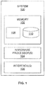
- FIG. 1 illustrates an exemplary block diagram of a system 100 for solving inverse problems using a coupled autoencoder 108 in accordance with an embodiment of the present disclosure.
- the system 100 includes one or more processors 104, communication interface device(s) or input/output (I/O) interface(s) 106, and one or more data storage devices or memory 102 operatively coupled to the one or more processors 104.
- the one or more processors 104 may be one or more software processing modules and/or hardware processors.
- the hardware processors can be implemented as one or more microprocessors, microcomputers, microcontrollers, digital signal processors, central processing units, state machines, logic circuitries, and/or any devices that manipulate signals based on operational instructions.
- the processor(s) is configured to fetch and execute computer-readable instructions stored in the memory.
- the device 100 can be implemented in a variety of computing systems, such as laptop computers, notebooks, hand-held devices, workstations, mainframe computers, servers, a network cloud and the like.
- the I/O interface device(s) 106 can include a variety of software and hardware interfaces, for example, a web interface, a graphical user interface, and the like and can facilitate multiple communications within a wide variety of networks N/W and protocol types, including wired networks, for example, LAN, cable, etc., and wireless networks, such as WLAN, cellular, or satellite.
- the I/O interface device(s) can include one or more ports for connecting a number of devices to one another or to another server.
- the memory 102 may include any computer-readable medium known in the art including, for example, volatile memory, such as static random access memory (SRAM) and dynamic random access memory (DRAM), and/or non-volatile memory, such as read only memory (ROM), erasable programmable ROM, flash memories, hard disks, optical disks, and magnetic tapes.
- volatile memory such as static random access memory (SRAM) and dynamic random access memory (DRAM)
- non-volatile memory such as read only memory (ROM), erasable programmable ROM, flash memories, hard disks, optical disks, and magnetic tapes.
- the coupled autoencoder 108 and a database 110 of the system 100 can be stored in the memory 102, wherein the database 110 may comprise, but are not limited to unknown corrupted samples, clean samples, training dataset, naturally-blurred and artificially-blurred images in the training dataset and undistorted, naturally blurred and artificially blurred images, learned variables and corresponding values, etc.
- FIG. 2 illustrates an exemplary flow diagram of a method for solving inverse problems using the coupled autoencoder 108 of the system 100 of FIG. 1 in accordance with an embodiment of the present disclosure.
- the system(s) 100 comprises one or more data storage devices or the memory 102 operatively coupled to the one or more hardware processors 104 and is configured to store instructions for execution of steps of the method by the one or more processors 104.
- the steps of the method of the present disclosure will now be explained with reference to the components of the system 100 as depicted in FIG. 1 , and the flow diagram.
- solving inverse problems may comprise, but are not limited to, generating clean images from blurred images, de-noising of noisy or distorted samples (or images), and so on.
- the one or more hardware processors 104 receives (202), via a source autoencoder, one or more corrupted samples (represented by a variable X S ) , wherein a first set of hidden layer representations of the source autoencoder is represented as a first proxy (Z S ) for the one or more corrupted image samples (X S ).
- the source autoencoder is configured to receive one or more corrupted samples from the database 110 (or manually fed by one or more users).
- the source autoencoder comprises a source encoder represented by a variable W ES and a source decoder represented by a variable W DS .
- a target autoencoder coupled to the source autoencoder wherein the target autoencoder is configured to receive, one or more corresponding clean image samples (represented by a variable X T ).
- a second set of hidden layer representations of the target autoencoder is represented as a second proxy represented by a variable Z T for the corresponding clean image samples represented by a variable X T .
- the target autoencoder comprises a target encoder represented by a variable W ET and a target decoder represented by a variable W DT .
- the target autoencoder is configured to receive one or more corresponding clean samples from the database 110 (or manually fed by one or more users).
- the first proxy Z S and the second proxy Z T are coupled, using a coupling mechanism (M), which form a Lagrangian formulation, and wherein a plurality of Bregman relaxation variables (B S ) and (B T ) are initialized for the source autoencoder and the target autoencoder respectively.
- M coupling mechanism
- the coupling mechanism M learns to map the representation from the source (corrupted) to the target (clean), which is expressed by way of example as illustrated below: argmin W DS , W ES , W DT , W ET , M ⁇ X S ⁇ W DS ⁇ W ES X S ⁇ 2 F + ⁇ X T ⁇ W DT ⁇ W ET X T ⁇ 2 F + ⁇ ⁇ ⁇ W ET X T ⁇ M ⁇ W ES X S ⁇ 2 F
- ⁇ X S - W DS ⁇ ( W ES X S ⁇ 2 F is autoencoder formulation for source
- ⁇ X T - W DT ⁇ ( W ET X T ) ⁇ 2 F is autoencoder formulation for target
- ⁇ ⁇ ⁇ ( W ET X T ) - M ⁇ ( W ES X S ) ⁇ 2 F is coupling term.
- the linear map M (or coupling mechanism) couples the representations (e.g., the one or more hidden layer representations) from the source to that of the target.
- the above expression is solved using a variable splitting technique.
- one or more Bregman relaxation variables are introduced B S and B T such that the value of the hyper-parameter need not be changed; the relaxation variable is updated in every iteration automatically so that it enforces equality at convergence.
- the split Bregman formulation is expressed as below by way of example: argmin W DS , W ES , W DT , W ET , M , Z S , Z T ⁇ X S ⁇ W DS Z S ⁇ 2 F + ⁇ X T ⁇ W DT Z T ⁇ 2 F + ⁇ ⁇ Z T ⁇ MZ S ⁇ 2 F + n ⁇ Z S ⁇ ⁇ W ES X S ⁇ B S ⁇ 2 F
- the coupled autoencoder 108 divides the above Lagrangian formulation as expressed in equation (2) into one or more sub-problems as expressed by way of examples below:
- P 1 argmin W DS ⁇ X S ⁇ W DS Z S ⁇ F 2
- P 2 argmin W DT ⁇ X T ⁇ W DT Z T ⁇ F 2
- P 3 argmin W ES ⁇ Z S ⁇ ⁇ W ES X S ⁇ B S ⁇ F 2 ⁇ argmin W ES ⁇ ⁇ ⁇ 1 Z S ⁇ B S ⁇ W ES X S ⁇ F 2
- P 4 argmin W ET ⁇ Z T ⁇ ⁇ W ET X T ⁇ B T ⁇ F 2 ⁇ argmin W ET ⁇ ⁇ ⁇ 1 Z T ⁇ B T ⁇ W ET X T ⁇ F 2
- P 5 argmin Z S ⁇ X S ⁇ W DS Z S ⁇ F 2 + ⁇ ⁇ Z T
- the above one or more sub-problems are solved by learning each of the source decoder (W DS ), the target decoder (W DT ), the first proxy (Z S ), the second proxy (Z T ), the coupling mechanism (M), the plurality of Bregman relaxation variables B S and B T , the source encoder (W ES ), the target encoder (W ET ) pertaining to the source autoencoder and the target autoencoder respectively.
- the step of learning each of the source decoder (W DS ), the target decoder (W DT ), the first proxy (Z S ), the second proxy (Z T ), the coupling mechanism (M), the plurality of Bregman relaxation variables B S and B T , the source encoder (W ES ), the target encoder (W ET ) pertaining to the source autoencoder and the target autoencoder respectively may comprise learning one or more values associated with each of the source decoder (W DS ), the target decoder (W DT ), the first proxy (Z S ), the second proxy (Z T ), the coupling mechanism (M), the plurality of Bregman relaxation variables B S and B T , the source encoder (W ES ), the target encoder (W ET ) pertaining to the source autoencoder and the target autoencoder respectively.
- sub-problems P1, P2, P5, P6, P7 are simple least squares problems having an analytic solution in the form of pseudoinverse.
- Sub-problems P3 and P4 are originally non-linear least squares problems; but since the activation function is trivial to invert (it is applied element-wise), P3 and P4 are converted to simple linear least squares problems and solved using pseudoinverse.
- the coupled autoencoder 108 iteratively updates the plurality of Bregman relaxation variables (B S ) and (B T ) using an optimization technique.
- the optimization technique is a gradient descent optimization technique.
- the plurality of Bregman relaxation variables (B S ) and (B T ) are iteratively updated by using the following expressions illustrated by way of examples: B S ⁇ ⁇ W ES X S + B S ⁇ Z S B T ⁇ ⁇ W ET X T + B T ⁇ Z T
- Iterations criteria is defined to be terminated when it reaches a specified maximum number of iterations or when the objective function converges to a local minimum. By convergence it is meant that the value of the objective function does not change much in successive iterations.
- the coupled autoencoder 108 is configured to receive an unknown corrupted sample
- the source decoder (W DS ) is configured to: receive the unknown corrupted sample from the coupled autoencoder 108, and one or more hidden layer representations of the unknown corrupted sample are obtained and transmitted to the coupling mechanism (M) which further transmits to the target encoder (W ET ).
- the coupled autoencoder 108 is further configured to: couple (e.g., using the coupling mechanism M), the obtained hidden layer representations with each other to obtain one or more hidden layer representations pertaining to the target autoencoder, and transmits the hidden layer representations pertaining to the target autoencoder to the target encoder for generation of a clean sample from the unknown corrupted sample.
- the target encoder then generates a clean sample (e.g., a clean image) from the unknown corrupted sample (e.g., a corrupted image or a blur image or a noisy image or a distorted image).
- Images from image blur dataset were used which contained 630 undistorted, 220 naturally-blurred and 150 artificially-blurred images in the training set and 619 undistorted, 411 naturally blurred and 450 artificially blurred images in the evaluation set. For performance evaluation a small subset of the dataset was considered. Around 50 images were taken for training, 20 images for testing and were corrupted with the motion blur kernels. The methodology was tested for two scenarios uniform kernel and non-uniform kernel. For training and testing, whole image was divided into number of overlapping patches. Each individual patch acts as a sample. The blurry patches are used to train the source autoencoder, the corresponding clean patches to train the target autoencoder and a mapping is learnt between the target and source representation.
- the blurred patch was given as the input of the source.
- the corresponding source representation was obtained from the source encoder from which the target representation is obtained by the coupling map.
- the decoder of the target was used to generate the clean (deblurred) patch.
- the whole image was reconstructed by placing patches at their locations and averaging at the overlapping regions. This eliminates the need of blocking artefacts and post processing of the recovered images. Patches of 40x40 with an overlapping of 20x20 were used for all the images.
- the input size for the autoencoders hence become 1600 and were learnt with 1400 hidden nodes.
- FIG. 3 illustrates an exemplary schematic diagram of the coupled autoencoder 108 of the system 100 according to an embodiment of the present disclosure.
- the proposed method of the present disclosure is also compared with existing techniques (ET) which estimates the kernel and retrieve deblurred image by deconvolution and which learns a Vectorized CNN for deblurring.
- E existing techniques
- the consolidated results are shown in below Table 1.
- the PSNR Peak signal-to-noise ratio
- SSIM structural similarity
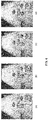
- FIG. 4 depict Non-uniform Blur Removal Comparison of the proposed methodology and existing techniques in accordance with an example embodiment of the present disclosure. More particularly, image (a) of FIG. 4 depicts Ground truth, image (b) of FIG. 4 depicts output generated by ET 3 (from Table 1), image (c) of FIG. 4 depicts output generated by ET 4 (from Table 1), and image (d) of FIG. 4 depicts output generated by the coupled autoencoder 108 of the system 100 of the present disclosure.
- PSNR, SSIM of ET 3 are 21.43 0.73 respectively, whereas PSNR, SSIM of ET 4 are 21.91 and 0.76 respectively, and PSNR, SSIM of the coupled autoencoder 108 of the system 100 of the present disclosure are 30.37 and 0.89 respectively.
- the hardware device can be any kind of device which can be programmed including e.g. any kind of computer like a server or a personal computer, or the like, or any combination thereof.
- the device may also include means which could be e.g. hardware means like e.g. an application-specific integrated circuit (ASIC), a field-programmable gate array (FPGA), or a combination of hardware and software means, e.g.
- ASIC application-specific integrated circuit
- FPGA field-programmable gate array
- the means can include both hardware means and software means.
- the method embodiments described herein could be implemented in hardware and software.
- the device may also include software means.
- the embodiments may be implemented on different hardware devices, e.g. using a plurality of CPUs.
- the embodiments herein can comprise hardware and software elements.
- the embodiments that are implemented in software include but are not limited to, firmware, resident software, microcode, etc.
- the functions performed by various modules described herein may be implemented in other modules or combinations of other modules.
- a computer-usable or computer readable medium can be any apparatus that can comprise, store, communicate, propagate, or transport the program for use by or in connection with the instruction execution system, apparatus, or device.
- a computer-readable storage medium refers to any type of physical memory on which information or data readable by a processor may be stored.
- a computer-readable storage medium may store instructions for execution by one or more processors, including instructions for causing the processor(s) to perform steps or stages consistent with the embodiments described herein.
- the term "computer-readable medium” should be understood to include tangible items and exclude carrier waves and transient signals, i.e., be non-transitory. Examples include random access memory (RAM), read-only memory (ROM), volatile memory, nonvolatile memory, hard drives, CD ROMs, DVDs, flash drives, disks, and any other known physical storage media.
Landscapes
- Engineering & Computer Science (AREA)
- Physics & Mathematics (AREA)
- Theoretical Computer Science (AREA)
- General Physics & Mathematics (AREA)
- Computational Linguistics (AREA)
- Data Mining & Analysis (AREA)
- Life Sciences & Earth Sciences (AREA)
- Artificial Intelligence (AREA)
- Biomedical Technology (AREA)
- Biophysics (AREA)
- Software Systems (AREA)
- Health & Medical Sciences (AREA)
- Evolutionary Computation (AREA)
- General Health & Medical Sciences (AREA)
- Molecular Biology (AREA)
- Computing Systems (AREA)
- General Engineering & Computer Science (AREA)
- Mathematical Physics (AREA)
- Multimedia (AREA)
- Compression Or Coding Systems Of Tv Signals (AREA)
Abstract
Description
- This patent application claims priority to India Patent Application
201721026251, filed on July 24, 2017 - The disclosure herein generally relate to a coupled autoencoder, and, more particularly, to systems and methods for solving inverse problems using a coupled autoencoder.
- An inverse problem in science is the process of calculating from a set of observations the causal factors that produced them: for example, calculating an image in computer tomography, etc. Inverse problems are some of the most important mathematical problems in science and mathematics because they tell about parameters that cannot be directly observed. They have wide application in signal processing, machine learning, image processing, etc. Motion blurring is one of the common source of image corruption in image processing techniques. It can be caused due to multiple reasons such as lens aberrations, camera shaking, long exposure time etc. The process of recovering sharp images from blurred images is termed as deblurring. Conventional deblurring techniques implement non-generalized kernel based approaches. However these approaches may not be efficient and are computational complex.
- Embodiments of the present disclosure present technological improvements as solutions to one or more of the above-mentioned technical problems recognized by the inventors in conventional systems. For example, in one aspect, a system for solving inverse problems is provided. The system comprising: a memory storing instructions; one or more communication interfaces; and one or more hardware processors coupled to the memory via the one or more communication interfaces, wherein the one or more hardware processors are configured by the instructions to execute: a coupled autoencoder stored in the memory, the coupled autoencoder comprising: a source autoencoder including a source encoder represented by a variable WES and a source decoder represented by a variable WDS, wherein the source autoencoder is configured to receive one or more corrupted samples represented by a variable XS, and wherein a first set of hidden layer representations of the source autoencoder is represented as a first proxy (ZS) for the one or more corrupted image samples (XS); a target autoencoder coupled to the source autoencoder, wherein the target autoencoder comprises a target encoder represented by a variable WET and a target decoder represented by a variable WDT, wherein the target autoencoder is configured to receive one or more corresponding clean image samples represented by a variable XT, wherein a second set of hidden layer representations of the target autoencoder is represented as a second proxy represented by a variable ZT for the corresponding clean image samples represented by a variable XT, wherein the ZS and ZT are coupled, using a coupling mechanism (M), which form a Lagrangian formulation, and wherein a plurality of Bregman relaxation variables (BS) and (BT) are initialized for the source autoencoder and the target autoencoder respectively; wherein the coupled autoencoder is configured to: divide the Lagrangian formulation into one or more sub-problems, solve the one or more sub-problems by learning each of the source decoder (WDS), the target decoder (WDT), the first proxy (ZS), the second proxy (ZT), the coupling mechanism (M), the plurality of Bregman relaxation variables BS and BT, the source encoder (WES), the target encoder (WET) pertaining to the source autoencoder and the target autoencoder respectively; and iteratively update the plurality of Bregman relaxation variables (BS) and (BT) using an optimization technique. In an embodiment, the Lagrangian formulation is solved using a Split Bregman technique. In an embodiment, the optimization technique is a gradient descent optimization technique. In an embodiment, the step of learning each of the source decoder (WDS), the target decoder (WDT), the first proxy (ZS), the second proxy (ZT), the coupling mechanism (M), the plurality of Bregman relaxation variables BS and BT, the source encoder (WES), the target encoder (WET) pertaining to the source autoencoder and the target autoencoder respectively comprising learning one or more values associated with each of the source decoder (WDS), the target decoder (WDT), the first proxy (ZS), the second proxy (ZT), the coupling mechanism (M), the plurality of Bregman relaxation variables BS and BT, the source encoder (WES), the target encoder (WET) pertaining to the source autoencoder and the target autoencoder respectively.
- In an embodiment, the coupled autoencoder is further configured to receive an unknown corrupted sample, and wherein a source decoder (WDS) is configured to: receive the unknown corrupted sample from the coupled autoencoder; obtain one or more hidden layer representations of the unknown corrupted sample and transmit to the coupling mechanism (M), wherein the coupling mechanism further transmits the obtained one or more hidden layer representations of the unknown corrupted sample to the target encoder (WET).
- In an embodiment, the coupled autoencoder is further configured to: couple the obtained hidden layer representations with each other to obtain one or more hidden layer representations pertaining to the target autoencoder; and transmit the hidden layer representations pertaining to the target autoencoder to the target encoder for generation of a clean sample from the unknown corrupted sample.
- In another aspect, a processor implemented method for solving inverse problems using a coupled autoencoder, the method comprising: receiving, by a source autoencoder, one or more corrupted samples represented by a variable XS, wherein a first set of hidden layer representations of the source autoencoder is represented as a first proxy (ZS) for the one or more corrupted image samples (XS), and wherein the source autoencoder including a source encoder represented by a variable WES and a source decoder represented by a variable WDS; receiving, by a target autoencoder coupled to the source autoencoder, one or more corresponding clean image samples represented by a variable XT, wherein a second set of hidden layer representations of the target autoencoder is represented as a second proxy represented by a variable ZT for the corresponding clean image samples represented by a variable XT, wherein the target autoencoder comprises a target encoder represented by a variable WET and a target decoder represented by a variable WDT, wherein the ZS and ZT are coupled, using a coupling mechanism (M), which form a Lagrangian formulation, and wherein a plurality of Bregman relaxation variables (BS) and (BT) are initialized for the source autoencoder and the target autoencoder respectively; dividing, by the coupled autoencoder, the Lagrangian formulation into one or more sub-problems; solving, by the coupled autoencoder, the one or more sub-problems by learning each of the source decoder (WDS), the target decoder (WDT), the first proxy (ZS), the second proxy (ZT), the coupling mechanism (M), the plurality of Bregman relaxation variables BS and BT, the source encoder (WES), the target encoder (WET) pertaining to the source autoencoder and the target autoencoder respectively; and iteratively updating, by the coupled autoencoder, the plurality of Bregman relaxation variables (BS) and (BT) using an optimization technique. In an embodiment, the optimization technique is a gradient descent optimization technique. In an embodiment, the step of learning each of the source decoder (WDS), the target decoder (WDT), the first proxy (ZS), the second proxy (ZT), the coupling mechanism (M), the plurality of Bregman relaxation variables BS and BT, the source encoder (WES), the target encoder (WET) pertaining to the source autoencoder and the target autoencoder respectively comprising learning one or more values associated with each of the source decoder (WDS), the target decoder (WDT), the first proxy (ZS), the second proxy (ZT), the coupling mechanism (M), the plurality of Bregman relaxation variables BS and BT, the source encoder (WES), the target encoder (WET) pertaining to the source autoencoder and the target autoencoder respectively.
- In an embodiment, the method may further comprise receiving, by a source decoder (WDS), an unknown corrupted sample; obtaining one or more hidden layer representations of the unknown corrupted sample and transmit to the coupling mechanism (M), wherein the coupling mechanism further transmits the obtained one or more hidden layer representations of the unknown corrupted sample and then to the target encoder (WET). In an embodiment, the method may further comprise coupling the obtained hidden layer representations to obtain one or more hidden layer representations pertaining to the target autoencoder; and transmitting the hidden layer representations pertaining to the target autoencoder to the target encoder for generation of a clean sample from the unknown corrupted sample.
- In an embodiment, the Lagrangian formulation is solved using a Split Bregman technique.
- In yet another aspect, one or more non-transitory machine readable information storage mediums comprising one or more instructions is provided. The one or more instructions which when executed by one or more hardware processors causes solving inverse problems using a coupled autoencoder. The instructions comprising: receiving, by a source autoencoder, one or more corrupted samples represented by a variable XS, wherein a first set of hidden layer representations of the source autoencoder is represented as a first proxy (ZS) for the one or more corrupted image samples (XS), and wherein the source autoencoder including a source encoder represented by a variable WES and a source decoder represented by a variable WDS; receiving, by a target autoencoder coupled to the source autoencoder, one or more corresponding clean image samples represented by a variable XT, wherein a second set of hidden layer representations of the target autoencoder is represented as a second proxy represented by a variable ZT for the corresponding clean image samples represented by a variable XT, wherein the target autoencoder comprises a target encoder represented by a variable WET and a target decoder represented by a variable WDT, wherein the ZS and ZT are coupled, using a coupling mechanism (M), which form a Lagrangian formulation, and wherein a plurality of Bregman relaxation variables (BS) and (BT) are initialized for the source autoencoder and the target autoencoder respectively; dividing, by the coupled autoencoder, the Lagrangian formulation into one or more sub-problems; solving, by the coupled autoencoder, the one or more sub-problems by learning each of the source decoder (WDS), the target decoder (WDT), the first proxy (ZS), the second proxy (ZT), the coupling mechanism (M), the plurality of Bregman relaxation variables BS and BT, the source encoder (WES), the target encoder (WET) pertaining to the source autoencoder and the target autoencoder respectively; and iteratively updating, by the coupled autoencoder, the plurality of Bregman relaxation variables (BS) and (BT) using an optimization technique. In an embodiment, the optimization technique is a gradient descent optimization technique.
- In an embodiment, the instructions which when executed by the hardware processors (or the coupled autoencoder) may further comprise receiving, by a source decoder (WDS), an unknown corrupted sample; obtaining one or more hidden layer representations of the unknown corrupted sample and transmit to the coupling mechanism (M), wherein the coupling mechanism further transmits the obtained one or more hidden layer representations of the unknown corrupted sample to the target encoder (WET). In an embodiment, the method may further comprise coupling the obtained hidden layer representations to obtain one or more hidden layer representations pertaining to the target autoencoder; and transmitting the hidden layer representations pertaining to the target autoencoder to the target encoder for generation of a clean sample from the unknown corrupted sample.
- In an embodiment, the Lagrangian formulation is solved using a Split Bregman technique. In an embodiment, the step of learning each of the source decoder (WDS), the target decoder (WDT), the first proxy (ZS), the second proxy (ZT), the coupling mechanism (M), the plurality of Bregman relaxation variables BS and BT, the source encoder (WES), the target encoder (WET) pertaining to the source autoencoder and the target autoencoder respectively comprising learning one or more values associated with each of the source decoder (WDS), the target decoder (WDT), the first proxy (ZS), the second proxy (ZT), the coupling mechanism (M), the plurality of Bregman relaxation variables BS and BT, the source encoder (WES), the target encoder (WET) pertaining to the source autoencoder and the target autoencoder respectively.
- It is to be understood that both the foregoing general description and the following detailed description are exemplary and explanatory only and are not restrictive of the invention, as claimed.
- The accompanying drawings, which are incorporated in and constitute a part of this disclosure, illustrate exemplary embodiments and, together with the description, serve to explain the disclosed principles:
-
FIG. 1 illustrates an exemplary block diagram of a system for solving inverse problems using a coupled autoencoder in accordance with an embodiment of the present disclosure. -
FIG. 2 illustrates an exemplary flow diagram of a method for solving inverse problems using the coupled autoencoder of the system ofFIG. 1 in accordance with an embodiment of the present disclosure. -
FIG. 3 illustrates an exemplary schematic diagram of the coupled autoencoder of the system ofFIG. 1 according to an embodiment of the present disclosure. -
FIG. 4 depict Non-uniform Blur Removal Comparison of the proposed methodology and existing techniques in accordance with an example embodiment of the present disclosure. - Exemplary embodiments are described with reference to the accompanying drawings. In the figures, the left-most digit(s) of a reference number identifies the figure in which the reference number first appears. Wherever convenient, the same reference numbers are used throughout the drawings to refer to the same or like parts. While examples and features of disclosed principles are described herein, modifications, adaptations, and other implementations are possible without departing from the spirit and scope of the disclosed embodiments. It is intended that the following detailed description be considered as exemplary only, with the true scope and spirit being indicated by the following claims.
- There are plethora of studies which use neural networks and Convolutional neural networks (CNNs) frameworks for solving computer vision tasks. The motivation for having fast deblurring techniques comes from the requirement of sharp and undistorted images for the purpose of SLAM (Simultaneous Localization and Mapping), visual odometers, optical flow, etc. There is a constant problem of motion blur while acquiring images and videos with the cameras fitted to the high speed motion devices, for example, drones. Distorted images intervene with the mapping of the visual points, hence the pose estimation and tracking may get corrupted.
- Embodiments of the present disclosure propose systems and methods for solving inverse problems using a coupled autoencoder. In an example embodiment, the embodiments of the present disclosure propose a joint optimization technique for coupled autoencoder which learns the autoencoder weights and coupling map (between source and target) simultaneously. The technique is applicable to any transfer learning problem. The embodiments of the present disclosure implements/proposes a new formulation that recasts deblurring as a transfer learning problem which is solved using the proposed coupled autoencoder. The embodiments of the present disclosure may be implemented in one or more fields, for example, optics, radar, acoustics, signal processing, medical imaging, computer vision, machine learning, and so on wherein input is unknown corrupted sample(s) to generate one or more clean samples thereof as output(s).
- Referring now to the drawings, and more particularly to
FIGS. 1 through 4 , where similar reference characters denote corresponding features consistently throughout the figures, there are shown preferred embodiments and these embodiments are described in the context of the following exemplary system and/or method. -
FIG. 1 illustrates an exemplary block diagram of asystem 100 for solving inverse problems using a coupledautoencoder 108 in accordance with an embodiment of the present disclosure. In an embodiment, thesystem 100 includes one ormore processors 104, communication interface device(s) or input/output (I/O) interface(s) 106, and one or more data storage devices ormemory 102 operatively coupled to the one ormore processors 104. The one ormore processors 104 may be one or more software processing modules and/or hardware processors. In an embodiment, the hardware processors can be implemented as one or more microprocessors, microcomputers, microcontrollers, digital signal processors, central processing units, state machines, logic circuitries, and/or any devices that manipulate signals based on operational instructions. Among other capabilities, the processor(s) is configured to fetch and execute computer-readable instructions stored in the memory. In an embodiment, thedevice 100 can be implemented in a variety of computing systems, such as laptop computers, notebooks, hand-held devices, workstations, mainframe computers, servers, a network cloud and the like. - The I/O interface device(s) 106 can include a variety of software and hardware interfaces, for example, a web interface, a graphical user interface, and the like and can facilitate multiple communications within a wide variety of networks N/W and protocol types, including wired networks, for example, LAN, cable, etc., and wireless networks, such as WLAN, cellular, or satellite. In an embodiment, the I/O interface device(s) can include one or more ports for connecting a number of devices to one another or to another server.
- The
memory 102 may include any computer-readable medium known in the art including, for example, volatile memory, such as static random access memory (SRAM) and dynamic random access memory (DRAM), and/or non-volatile memory, such as read only memory (ROM), erasable programmable ROM, flash memories, hard disks, optical disks, and magnetic tapes. In an embodiment, the coupled autoencoder 108 and adatabase 110 of thesystem 100 can be stored in thememory 102, wherein thedatabase 110 may comprise, but are not limited to unknown corrupted samples, clean samples, training dataset, naturally-blurred and artificially-blurred images in the training dataset and undistorted, naturally blurred and artificially blurred images, learned variables and corresponding values, etc. -
FIG. 2 , with reference toFIG. 1 , illustrates an exemplary flow diagram of a method for solving inverse problems using the coupled autoencoder 108 of thesystem 100 ofFIG. 1 in accordance with an embodiment of the present disclosure. In an embodiment, the system(s) 100 comprises one or more data storage devices or thememory 102 operatively coupled to the one ormore hardware processors 104 and is configured to store instructions for execution of steps of the method by the one ormore processors 104. The steps of the method of the present disclosure will now be explained with reference to the components of thesystem 100 as depicted inFIG. 1 , and the flow diagram. In an embodiment, solving inverse problems may comprise, but are not limited to, generating clean images from blurred images, de-noising of noisy or distorted samples (or images), and so on. In an embodiment of the present disclosure, atstep 202, the one ormore hardware processors 104 receives (202), via a source autoencoder, one or more corrupted samples (represented by a variable XS), wherein a first set of hidden layer representations of the source autoencoder is represented as a first proxy (ZS) for the one or more corrupted image samples (XS). In an embodiment the source autoencoder is configured to receive one or more corrupted samples from the database 110 (or manually fed by one or more users). In an embodiment, the source autoencoder comprises a source encoder represented by a variable WES and a source decoder represented by a variable WDS. In an embodiment of the present disclosure, atstep 204, a target autoencoder coupled to the source autoencoder wherein the target autoencoder is configured to receive, one or more corresponding clean image samples (represented by a variable XT). In an embodiment, a second set of hidden layer representations of the target autoencoder is represented as a second proxy represented by a variable ZT for the corresponding clean image samples represented by a variable XT. The target autoencoder comprises a target encoder represented by a variable WET and a target decoder represented by a variable WDT. In an embodiment, the target autoencoder is configured to receive one or more corresponding clean samples from the database 110 (or manually fed by one or more users). The first proxy ZS and the second proxy ZT are coupled, using a coupling mechanism (M), which form a Lagrangian formulation, and wherein a plurality of Bregman relaxation variables (BS) and (BT) are initialized for the source autoencoder and the target autoencoder respectively. The coupling mechanism M learns to map the representation from the source (corrupted) to the target (clean), which is expressed by way of example as illustrated below:

- In an embodiment of the present disclosure, at step 206, the coupled autoencoder 108 divides the above Lagrangian formulation as expressed in equation (2) into one or more sub-problems as expressed by way of examples below:


- In an embodiment of the present disclosure, at
step 208, the above one or more sub-problems (PI till P7) are solved by learning each of the source decoder (WDS), the target decoder (WDT), the first proxy (ZS), the second proxy (ZT), the coupling mechanism (M), the plurality of Bregman relaxation variables BS and BT, the source encoder (WES), the target encoder (WET) pertaining to the source autoencoder and the target autoencoder respectively. In an embodiment, the step of learning each of the source decoder (WDS), the target decoder (WDT), the first proxy (ZS), the second proxy (ZT), the coupling mechanism (M), the plurality of Bregman relaxation variables BS and BT, the source encoder (WES), the target encoder (WET) pertaining to the source autoencoder and the target autoencoder respectively may comprise learning one or more values associated with each of the source decoder (WDS), the target decoder (WDT), the first proxy (ZS), the second proxy (ZT), the coupling mechanism (M), the plurality of Bregman relaxation variables BS and BT, the source encoder (WES), the target encoder (WET) pertaining to the source autoencoder and the target autoencoder respectively. In an embodiment, sub-problems P1, P2, P5, P6, P7 are simple least squares problems having an analytic solution in the form of pseudoinverse. Sub-problems P3 and P4 are originally non-linear least squares problems; but since the activation function is trivial to invert (it is applied element-wise), P3 and P4 are converted to simple linear least squares problems and solved using pseudoinverse. In an embodiment of the present disclosure, atstep 210, the coupledautoencoder 108 iteratively updates the plurality of Bregman relaxation variables (BS) and (BT) using an optimization technique. In an embodiment, the optimization technique is a gradient descent optimization technique. In an embodiment, the plurality of Bregman relaxation variables (BS) and (BT) are iteratively updated by using the following expressions illustrated by way of examples:

- Iterations criteria is defined to be terminated when it reaches a specified maximum number of iterations or when the objective function converges to a local minimum. By convergence it is meant that the value of the objective function does not change much in successive iterations.
- Upon learning each of the above variables mentioned, the coupled
autoencoder 108 is configured to receive an unknown corrupted sample, wherein the source decoder (WDS) is configured to: receive the unknown corrupted sample from the coupledautoencoder 108, and one or more hidden layer representations of the unknown corrupted sample are obtained and transmitted to the coupling mechanism (M) which further transmits to the target encoder (WET). - The coupled autoencoder 108 is further configured to: couple (e.g., using the coupling mechanism M), the obtained hidden layer representations with each other to obtain one or more hidden layer representations pertaining to the target autoencoder, and transmits the hidden layer representations pertaining to the target autoencoder to the target encoder for generation of a clean sample from the unknown corrupted sample. The target encoder then generates a clean sample (e.g., a clean image) from the unknown corrupted sample (e.g., a corrupted image or a blur image or a noisy image or a distorted image).
- Images from image blur dataset were used which contained 630 undistorted, 220 naturally-blurred and 150 artificially-blurred images in the training set and 619 undistorted, 411 naturally blurred and 450 artificially blurred images in the evaluation set. For performance evaluation a small subset of the dataset was considered. Around 50 images were taken for training, 20 images for testing and were corrupted with the motion blur kernels. The methodology was tested for two scenarios uniform kernel and non-uniform kernel. For training and testing, whole image was divided into number of overlapping patches. Each individual patch acts as a sample. The blurry patches are used to train the source autoencoder, the corresponding clean patches to train the target autoencoder and a mapping is learnt between the target and source representation. The above training and mapping is carried out without having to preprocess the images or patches. During testing, the blurred patch was given as the input of the source. The corresponding source representation was obtained from the source encoder from which the target representation is obtained by the coupling map. Once the target representation is obtained, the decoder of the target was used to generate the clean (deblurred) patch. Once all the individual patches of the testing image are deblurred, the whole image was reconstructed by placing patches at their locations and averaging at the overlapping regions. This eliminates the need of blocking artefacts and post processing of the recovered images. Patches of 40x40 with an overlapping of 20x20 were used for all the images. The input size for the autoencoders hence become 1600 and were learnt with 1400 hidden nodes. There are just two parameters λ and n while training which do not require much tuning. Whereas the testing is parameter free. The testing flow is depicted in
FIG. 3 . More particularly,FIG. 3 illustrates an exemplary schematic diagram of the coupled autoencoder 108 of thesystem 100 according to an embodiment of the present disclosure. - The proposed method of the present disclosure is also compared with existing techniques (ET) which estimates the kernel and retrieve deblurred image by deconvolution and which learns a Vectorized CNN for deblurring. The consolidated results are shown in below Table 1. The PSNR (Peak signal-to-noise ratio) and SSIM (structural similarity) values are averaged over for all the 20 testing images.
Blur Type ET1 ET2 ET3 ET4 ET5 ET6 Proposed technique Uniform Blur (PSNR) 23.7679 23.5257 23.6927 22.9265 25.6540 20.9342 30.8893 (SSIM) 0.6929 0.6899 0.7015 0.6620 0.7708 0.7312 0.8787 Non-uniform Blur (PSNR) 20.3013 20.4161 19.6594 20.5548 19.9718 20.8226 29.6364 (SSIM) 0.5402 0.5361 0.5345 0.5812 0.5692 0.7328 0.8711 - As can be depicted from above Table 1, that the proposed methodology provides or yields better results on both PSNR and SSIM for both uniform and non-uniform blur. The experimentation showed that the framework can learn characteristics for different kinds of motion blur and yields good performances on them as well.
-
FIG. 4 , with reference toFIGS. 1 through 3 , depict Non-uniform Blur Removal Comparison of the proposed methodology and existing techniques in accordance with an example embodiment of the present disclosure. More particularly, image (a) ofFIG. 4 depicts Ground truth, image (b) ofFIG. 4 depicts output generated by ET 3 (from Table 1), image (c) ofFIG. 4 depicts output generated by ET 4 (from Table 1), and image (d) ofFIG. 4 depicts output generated by the coupled autoencoder 108 of thesystem 100 of the present disclosure. PSNR, SSIM of ET 3 are 21.43 0.73 respectively, whereas PSNR, SSIM of ET 4 are 21.91 and 0.76 respectively, and PSNR, SSIM of the coupled autoencoder 108 of thesystem 100 of the present disclosure are 30.37 and 0.89 respectively. - The written description describes the subject matter herein to enable any person skilled in the art to make and use the embodiments. The scope of the subject matter embodiments is defined by the claims and may include other modifications that occur to those skilled in the art. Such other modifications are intended to be within the scope of the claims if they have similar elements that do not differ from the literal language of the claims or if they include equivalent elements with insubstantial differences from the literal language of the claims.
- It is to be understood that the scope of the protection is extended to such a program and in addition to a computer-readable means having a message therein; such computer-readable storage means contain program-code means for implementation of one or more steps of the method, when the program runs on a server or mobile device or any suitable programmable device. The hardware device can be any kind of device which can be programmed including e.g. any kind of computer like a server or a personal computer, or the like, or any combination thereof. The device may also include means which could be e.g. hardware means like e.g. an application-specific integrated circuit (ASIC), a field-programmable gate array (FPGA), or a combination of hardware and software means, e.g. an ASIC and an FPGA, or at least one microprocessor and at least one memory with software modules located therein. Thus, the means can include both hardware means and software means. The method embodiments described herein could be implemented in hardware and software. The device may also include software means. Alternatively, the embodiments may be implemented on different hardware devices, e.g. using a plurality of CPUs.
- The embodiments herein can comprise hardware and software elements. The embodiments that are implemented in software include but are not limited to, firmware, resident software, microcode, etc. The functions performed by various modules described herein may be implemented in other modules or combinations of other modules. For the purposes of this description, a computer-usable or computer readable medium can be any apparatus that can comprise, store, communicate, propagate, or transport the program for use by or in connection with the instruction execution system, apparatus, or device.
- The illustrated steps are set out to explain the exemplary embodiments shown, and it should be anticipated that ongoing technological development will change the manner in which particular functions are performed. These examples are presented herein for purposes of illustration, and not limitation. Further, the boundaries of the functional building blocks have been arbitrarily defined herein for the convenience of the description. Alternative boundaries can be defined so long as the specified functions and relationships thereof are appropriately performed. Alternatives (including equivalents, extensions, variations, deviations, etc., of those described herein) will be apparent to persons skilled in the relevant art(s) based on the teachings contained herein. Such alternatives fall within the scope and spirit of the disclosed embodiments. Also, the words "comprising," "having," "containing," and "including," and other similar forms are intended to be equivalent in meaning and be open ended in that an item or items following any one of these words is not meant to be an exhaustive listing of such item or items, or meant to be limited to only the listed item or items. It must also be noted that as used herein and in the appended claims, the singular forms "a," "an," and "the" include plural references unless the context clearly dictates otherwise.
- Furthermore, one or more computer-readable storage media may be utilized in implementing embodiments consistent with the present disclosure. A computer-readable storage medium refers to any type of physical memory on which information or data readable by a processor may be stored. Thus, a computer-readable storage medium may store instructions for execution by one or more processors, including instructions for causing the processor(s) to perform steps or stages consistent with the embodiments described herein. The term "computer-readable medium" should be understood to include tangible items and exclude carrier waves and transient signals, i.e., be non-transitory. Examples include random access memory (RAM), read-only memory (ROM), volatile memory, nonvolatile memory, hard drives, CD ROMs, DVDs, flash drives, disks, and any other known physical storage media.
- It is intended that the disclosure and examples be considered as exemplary only, with a true scope and spirit of disclosed embodiments being indicated by the following claims.
Claims (15)
- A system (100) for solving inverse problems comprising:a memory (102) storing instructions;one or more communication interfaces (106); andone or more hardware processors (104) coupled to the memory (102) via the one or more communication interfaces (106), wherein the one or more hardware processors (104) are configured by the instructions to execute:a coupled autoencoder stored in the memory, the coupled autoencoder comprising:a source autoencoder including a source encoder represented by a variable WES and a source decoder represented by a variable WDS, wherein the source autoencoder is configured to receive one or more corrupted samples represented by a variable XS, and wherein a first set of hidden layer representations of the source autoencoder is represented as a first proxy (ZS) for the one or more corrupted image samples (XS);a target autoencoder coupled to the source autoencoder, wherein the target autoencoder comprises a target encoder represented by a variable WET and a target decoder represented by a variable WDT, wherein the target autoencoder is configured to receive one or more corresponding clean image samples represented by a variable XT, wherein a second set of hidden layer representations of the target autoencoder is represented as a second proxy represented by a variable ZT for the corresponding clean image samples represented by a variable XT, wherein the ZS and ZT are coupled, using a coupling mechanism (M), which form a Lagrangian formulation, and wherein a plurality of Bregman relaxation variables (BS) and (BT) are initialized for the source autoencoder and the target autoencoder respectively;wherein the coupled autoencoder is configured to:divide the Lagrangian formulation into one or more sub-problems,solve the one or more sub-problems by learning each of the source decoder (WDS), the target decoder (WDT), the first proxy (ZS), the second proxy (ZT), the coupling mechanism (M), the plurality of Bregman relaxation variables BS and BT, the source encoder (WES), the target encoder (WET) pertaining to the source autoencoder and the target autoencoder respectively; anditeratively update the plurality of Bregman relaxation variables (BS) and (BT) using an optimization technique.
- The system of claim 1, wherein the coupled autoencoder is further configured to receive an unknown corrupted sample, and wherein the source decoder (WDS) is configured to:receive the unknown corrupted sample from the coupled autoencoder;obtain one or more hidden layer representations of the unknown corrupted sample and transmit to the coupling mechanism (M), wherein the coupling mechanism (M) further transmits the obtained one or more hidden layer representations of the unknown corrupted sample to the target encoder (WET).
- The system of claim 2, wherein the coupled autoencoder is further configured to:couple the obtained hidden layer representations with each other to obtain one or more hidden layer representations pertaining to the target autoencoder; andtransmit the hidden layer representations pertaining to the target autoencoder to the target encoder (WET) for generation of a clean sample from the unknown corrupted sample.
- The system of claim 1, wherein the Lagrangian formulation is solved using a Split Bregman technique.
- The system of claim 1, wherein the optimization technique is a gradient descent optimization technique, and wherein the step of learning each of the source decoder (WDS), the target decoder (WDT), the first proxy (ZS), the second proxy (ZT), the coupling mechanism (M), the plurality of Bregman relaxation variables BS and BT, the source encoder (WES), the target encoder (WET) pertaining to the source autoencoder and the target autoencoder respectively comprising learning one or more values associated with each of the source decoder (WDS), the target decoder (WDT), the first proxy (ZS), the second proxy (ZT), the coupling mechanism (M), the plurality of Bregman relaxation variables BS and BT, the source encoder (WES), the target encoder (WET) pertaining to the source autoencoder and the target autoencoder respectively.
- A processor implemented method for solving inverse problems using a coupled autoencoder, the method comprising:receiving (202), by a source autoencoder, one or more corrupted samples represented by a variable XS, wherein a first set of hidden layer representations of the source autoencoder is represented as a first proxy (ZS) for the one or more corrupted image samples (XS), and wherein the source autoencoder including a source encoder represented by a variable WES and a source decoder represented by a variable WDS;receiving (204), by a target autoencoder coupled to the source autoencoder, one or more corresponding clean image samples represented by a variable XT, wherein a second set of hidden layer representations of the target autoencoder is represented as a second proxy represented by a variable ZT for the corresponding clean image samples represented by a variable XT, wherein the target autoencoder comprises a target encoder represented by a variable WET and a target decoder represented by a variable WDT, wherein the ZS and ZT are coupled, using a coupling mechanism (M), which form a Lagrangian formulation, and wherein a plurality of Bregman relaxation variables (BS) and (BT) are initialized for the source autoencoder and the target autoencoder respectively;dividing (206), by the coupled autoencoder, the Lagrangian formulation into one or more sub-problems;solving (208), by the coupled autoencoder, the one or more sub-problems by learning each of the source decoder (WDS), the target decoder (WDT), the first proxy (ZS), the second proxy (ZT), the coupling mechanism (M), the plurality of Bregman relaxation variables BS and BT, the source encoder (WES), the target encoder (WET) pertaining to the source autoencoder and the target autoencoder respectively; anditeratively updating (210), by the coupled autoencoder, the plurality of Bregman relaxation variables (BS) and (BT) using an optimization technique.
- The method of claim 6, further comprising:receiving, by a source decoder (WDS), an unknown corrupted sample;obtaining one or more hidden layer representations of the unknown corrupted sample and transmit to the coupling mechanism (M), wherein the coupling mechanism further transmits the obtained one or more hidden layer representations of the unknown corrupted sample to the target encoder (WET).
- The method of claim 7, further comprising:coupling the obtained hidden layer representations with each other to obtain one or more hidden layer representations pertaining to the target autoencoder; andtransmitting the hidden layer representations pertaining to the target autoencoder to the target encoder (WET) for generation of a clean sample from the unknown corrupted sample.
- The method of claim 6, wherein the Lagrangian formulation is solved using a Split Bregman technique.
- The method of claim 6, wherein the optimization technique is a gradient descent optimization technique, and wherein the step of learning each of the source decoder (WDS), the target decoder (WDT), the first proxy (ZS), the second proxy (ZT), the coupling mechanism (M), the plurality of Bregman relaxation variables BS and BT, the source encoder (WES), the target encoder (WET) pertaining to the source autoencoder and the target autoencoder respectively comprising learning one or more values associated with each of the source decoder (WDS), the target decoder (WDT), the first proxy (ZS), the second proxy (ZT), the coupling mechanism (M), the plurality of Bregman relaxation variables BS and BT, the source encoder (WES), the target encoder (WET) pertaining to the source autoencoder and the target autoencoder respectively.
- One or more non-transitory machine readable information storage mediums comprising one or more instructions which when executed by one or more hardware processors causes:receiving, by a source autoencoder of a coupled autoencoder, one or more corrupted samples represented by a variable XS, wherein a first set of hidden layer representations of the source autoencoder is represented as a first proxy (ZS) for the one or more corrupted image samples (XS), and wherein the source autoencoder including a source encoder represented by a variable WES and a source decoder represented by a variable WDS;receiving, by a target autoencoder coupled to the source autoencoder, one or more corresponding clean image samples represented by a variable XT, wherein a second set of hidden layer representations of the target autoencoder is represented as a second proxy represented by a variable ZT for the corresponding clean image samples represented by a variable XT, wherein the target autoencoder comprises a target encoder represented by a variable WET and a target decoder represented by a variable WDT, wherein the ZS and ZT are coupled, using a coupling mechanism (M), which form a Lagrangian formulation, and wherein a plurality of Bregman relaxation variables (BS) and (BT) are initialized for the source autoencoder and the target autoencoder respectively;dividing, by the coupled autoencoder, the Lagrangian formulation into one or more sub-problems;solving, by the coupled autoencoder, the one or more sub-problems by learning each of the source decoder (WDS), the target decoder (WDT), the first proxy (ZS), the second proxy (ZT), the coupling mechanism (M), the plurality of Bregman relaxation variables BS and BT, the source encoder (WES), the target encoder (WET) pertaining to the source autoencoder and the target autoencoder respectively; anditeratively updating, by the coupled autoencoder, the plurality of Bregman relaxation variables (BS) and (BT) using an optimization technique.
- The one or more non-transitory machine readable information storage mediums of claim 11, wherein the instructions when executed by the one or more hardware processors further cause:receiving, by a source decoder (WDS), an unknown corrupted sample;obtaining one or more hidden layer representations of the unknown corrupted sample and transmit to the coupling mechanism (M), wherein the coupling mechanism further transmits the obtained one or more hidden layer representations of the unknown corrupted sample to the target encoder (WET).
- The one or more non-transitory machine readable information storage mediums of claim 11, wherein the instructions when executed by the one or more hardware processors further cause:coupling the obtained hidden layer representations with each other to obtain one or more hidden layer representations pertaining to the target autoencoder; andtransmitting the hidden layer representations pertaining to the target autoencoder to the target encoder (WET) for generation of a clean sample from the unknown corrupted sample.
- The one or more non-transitory machine readable information storage mediums of claim 11, wherein the Lagrangian formulation is solved using a Split Bregman technique.
- The one or more non-transitory machine readable information storage mediums of claim 11, wherein the optimization technique is a gradient descent optimization technique, and wherein the step of learning each of the source decoder (WDS), the target decoder (WDT), the first proxy (ZS), the second proxy (ZT), the coupling mechanism (M), the plurality of Bregman relaxation variables BS and BT, the source encoder (WES), the target encoder (WET) pertaining to the source autoencoder and the target autoencoder respectively comprising learning one or more values associated with each of the source decoder (WDS), the target decoder (WDT), the first proxy (ZS), the second proxy (ZT), the coupling mechanism (M), the plurality of Bregman relaxation variables BS and BT, the source encoder (WES), the target encoder (WET) pertaining to the source autoencoder and the target autoencoder respectively.
Applications Claiming Priority (1)
| Application Number | Priority Date | Filing Date | Title |
|---|---|---|---|
| IN201721026251 | 2017-07-24 |
Publications (3)
| Publication Number | Publication Date |
|---|---|
| EP3435294A1 true EP3435294A1 (en) | 2019-01-30 |
| EP3435294B1 EP3435294B1 (en) | 2024-04-03 |
| EP3435294C0 EP3435294C0 (en) | 2024-04-03 |
Family
ID=61198711
Family Applications (1)
| Application Number | Title | Priority Date | Filing Date |
|---|---|---|---|
| EP18156212.5A Active EP3435294B1 (en) | 2017-07-24 | 2018-02-12 | Systems and methods for solving inverse problems using a coupled autoencoder |
Country Status (2)
| Country | Link |
|---|---|
| US (1) | US10360665B2 (en) |
| EP (1) | EP3435294B1 (en) |
Families Citing this family (7)
| Publication number | Priority date | Publication date | Assignee | Title |
|---|---|---|---|---|
| US11222409B2 (en) * | 2019-05-22 | 2022-01-11 | Nec Corporation | Image/video deblurring using convolutional neural networks with applications to SFM/SLAM with blurred images/videos |
| US11126895B2 (en) * | 2019-05-22 | 2021-09-21 | Lawrence Livermore National Security, Llc | Mimicking of corruption in images |
| US11664820B2 (en) * | 2019-09-25 | 2023-05-30 | Nokia Technologies Oy | Domain adaptation |
| CN110751651B (en) * | 2019-09-27 | 2022-03-04 | 西安电子科技大学 | MRI pancreas image segmentation method based on multi-scale migration learning |
| US12468952B2 (en) * | 2020-06-02 | 2025-11-11 | Salesforce, Inc. | Systems and methods for noise-robust contrastive learning |
| US20220415037A1 (en) * | 2021-06-24 | 2022-12-29 | Meta Platforms, Inc. | Video corruption detection |
| US12437194B2 (en) * | 2021-06-28 | 2025-10-07 | International Business Machines Corporation | Mechanistic model parameter inference through artificial intelligence |
Family Cites Families (2)
| Publication number | Priority date | Publication date | Assignee | Title |
|---|---|---|---|---|
| US8873813B2 (en) | 2012-09-17 | 2014-10-28 | Z Advanced Computing, Inc. | Application of Z-webs and Z-factors to analytics, search engine, learning, recognition, natural language, and other utilities |
| US11205103B2 (en) * | 2016-12-09 | 2021-12-21 | The Research Foundation for the State University | Semisupervised autoencoder for sentiment analysis |
-
2018
- 2018-02-12 EP EP18156212.5A patent/EP3435294B1/en active Active
- 2018-02-15 US US15/898,144 patent/US10360665B2/en active Active
Non-Patent Citations (4)
| Title |
|---|
| GUPTA KAVYA ET AL: "Motion blur removal via coupled autoencoder", 2017 IEEE INTERNATIONAL CONFERENCE ON IMAGE PROCESSING (ICIP), IEEE, 17 September 2017 (2017-09-17), pages 480 - 484, XP033322623, DOI: 10.1109/ICIP.2017.8296327 * |
| PASCAL VINCENT ET AL: "Stacked Denoising Autoencoders: Learning Useful Representations in a Deep Network with a Local Denoising Criterion", JOURNAL OF MACHINE LEARNING RESEARCH, MIT PRESS, CAMBRIDGE, MA, US, vol. 11, 1 December 2010 (2010-12-01), pages 3371 - 3408, XP058336476, ISSN: 1532-4435 * |
| SHUYANG WANG ET AL: "Coupled Marginalized Auto-Encoders for Cross-Domain Multi-View Learning", PROCEEDINGS OF THE TWENTY-FIFTH INTERNATIONAL JOINT CONFERENCE ON ARTIFICIAL INTELLIGENCE (IJCAI-16), 9 July 2016 (2016-07-09), pages 2125 - 2131, XP055495993, ISBN: 978-1-57735-770-4, Retrieved from the Internet <URL:https://www.ijcai.org/Proceedings/16/Papers/303.pdf> [retrieved on 20180730] * |
| TOM GOLDSTEIN ET AL: "The Split Bregman Method for L1-Regularized Problems", SIAM JOURNAL ON IMAGING SCIENCES, vol. 2, no. 2, 1 January 2009 (2009-01-01), pages 323 - 343, XP055496159, DOI: 10.1137/080725891 * |
Also Published As
| Publication number | Publication date |
|---|---|
| US20190026869A1 (en) | 2019-01-24 |
| US10360665B2 (en) | 2019-07-23 |
| EP3435294B1 (en) | 2024-04-03 |
| EP3435294C0 (en) | 2024-04-03 |
Similar Documents
| Publication | Publication Date | Title |
|---|---|---|
| EP3435294B1 (en) | Systems and methods for solving inverse problems using a coupled autoencoder | |
| US20250371345A1 (en) | Image-to-Image Mapping by Iterative De-Noising | |
| US9953246B2 (en) | Feature-preserving noise removal | |
| CN111178542B (en) | System and method based on machine learning modeling | |
| Singh et al. | Single image dehazing for a variety of haze scenarios using back projected pyramid network | |
| Zhussip et al. | Training deep learning based image denoisers from undersampled measurements without ground truth and without image prior | |
| DE102022121649A1 (en) | Fast retraining of fully fused neural transceiver components | |
| US20200372308A1 (en) | Mimicking of corruption in images | |
| US11741579B2 (en) | Methods and systems for deblurring blurry images | |
| Chen et al. | Deep Richardson–Lucy deconvolution for low-light image deblurring | |
| Zhang et al. | A fast algorithm for deconvolution and Poisson noise removal | |
| US20200244842A1 (en) | Video processing method and device, unmanned aerial vehicle, and computer-readable storage medium | |
| US20140105515A1 (en) | Stabilizing and Deblurring Atmospheric Turbulence | |
| CN113256529A (en) | Image processing method, image processing device, computer equipment and storage medium | |
| Wannenwetsch et al. | Probabilistic pixel-adaptive refinement networks | |
| Xiao et al. | Sequential image recovery using joint hierarchical Bayesian learning | |
| Zhang et al. | High‐Order Total Bounded Variation Model and Its Fast Algorithm for Poissonian Image Restoration | |
| Teodoro et al. | Image restoration with locally selected class-adapted models | |
| Whitney et al. | Generative modelling for mass-mapping with fast uncertainty quantification | |
| US20180300588A1 (en) | Fully parallel, low complexity approach to solving computer vision problems | |
| EP3594865B1 (en) | Systems and methods for coupled representation using transform learning for solving inverse problems | |
| Mohana Dhas et al. | Blood cell image denoising based on tunicate rat swarm optimization with median filter | |
| US12175667B2 (en) | On-site training of a machine-learning algorithm for generating synthetic imaging data | |
| US20250278820A1 (en) | Towards unsupervised blind face restoration using diffusion models | |
| CN119907989A (en) | Image enhancement based on removing image degradation by learning from multiple machine learning models |
Legal Events
| Date | Code | Title | Description |
|---|---|---|---|
| PUAI | Public reference made under article 153(3) epc to a published international application that has entered the european phase |
Free format text: ORIGINAL CODE: 0009012 |
|
| STAA | Information on the status of an ep patent application or granted ep patent |
Free format text: STATUS: THE APPLICATION HAS BEEN PUBLISHED |
|
| AK | Designated contracting states |
Kind code of ref document: A1 Designated state(s): AL AT BE BG CH CY CZ DE DK EE ES FI FR GB GR HR HU IE IS IT LI LT LU LV MC MK MT NL NO PL PT RO RS SE SI SK SM TR |
|
| AX | Request for extension of the european patent |
Extension state: BA ME |
|
| STAA | Information on the status of an ep patent application or granted ep patent |
Free format text: STATUS: REQUEST FOR EXAMINATION WAS MADE |
|
| 17P | Request for examination filed |
Effective date: 20190730 |
|
| RBV | Designated contracting states (corrected) |
Designated state(s): AL AT BE BG CH CY CZ DE DK EE ES FI FR GB GR HR HU IE IS IT LI LT LU LV MC MK MT NL NO PL PT RO RS SE SI SK SM TR |
|
| STAA | Information on the status of an ep patent application or granted ep patent |
Free format text: STATUS: EXAMINATION IS IN PROGRESS |
|
| 17Q | First examination report despatched |
Effective date: 20200827 |
|
| REG | Reference to a national code |
Ref country code: DE Ref legal event code: R079 Free format text: PREVIOUS MAIN CLASS: G06N0003040000 Ipc: G06N0003045500 Ref document number: 602018067383 Country of ref document: DE |
|
| GRAP | Despatch of communication of intention to grant a patent |
Free format text: ORIGINAL CODE: EPIDOSNIGR1 |
|
| STAA | Information on the status of an ep patent application or granted ep patent |
Free format text: STATUS: GRANT OF PATENT IS INTENDED |
|
| RIC1 | Information provided on ipc code assigned before grant |
Ipc: G06T 5/00 20060101ALI20230919BHEP Ipc: G06N 3/094 20230101ALI20230919BHEP Ipc: G06N 3/0455 20230101AFI20230919BHEP |
|
| INTG | Intention to grant announced |
Effective date: 20231010 |
|
| GRAS | Grant fee paid |
Free format text: ORIGINAL CODE: EPIDOSNIGR3 |
|
| GRAA | (expected) grant |
Free format text: ORIGINAL CODE: 0009210 |
|
| STAA | Information on the status of an ep patent application or granted ep patent |
Free format text: STATUS: THE PATENT HAS BEEN GRANTED |
|
| AK | Designated contracting states |
Kind code of ref document: B1 Designated state(s): AL AT BE BG CH CY CZ DE DK EE ES FI FR GB GR HR HU IE IS IT LI LT LU LV MC MK MT NL NO PL PT RO RS SE SI SK SM TR |
|
| REG | Reference to a national code |
Ref country code: GB Ref legal event code: FG4D |
|
| REG | Reference to a national code |
Ref country code: CH Ref legal event code: EP |
|
| REG | Reference to a national code |
Ref country code: IE Ref legal event code: FG4D |
|
| REG | Reference to a national code |
Ref country code: DE Ref legal event code: R096 Ref document number: 602018067383 Country of ref document: DE |
|
| U01 | Request for unitary effect filed |
Effective date: 20240430 |
|
| U07 | Unitary effect registered |
Designated state(s): AT BE BG DE DK EE FI FR IT LT LU LV MT NL PT SE SI Effective date: 20240507 |
|
| PG25 | Lapsed in a contracting state [announced via postgrant information from national office to epo] |
Ref country code: IS Free format text: LAPSE BECAUSE OF FAILURE TO SUBMIT A TRANSLATION OF THE DESCRIPTION OR TO PAY THE FEE WITHIN THE PRESCRIBED TIME-LIMIT Effective date: 20240803 |
|
| PG25 | Lapsed in a contracting state [announced via postgrant information from national office to epo] |
Ref country code: HR Free format text: LAPSE BECAUSE OF FAILURE TO SUBMIT A TRANSLATION OF THE DESCRIPTION OR TO PAY THE FEE WITHIN THE PRESCRIBED TIME-LIMIT Effective date: 20240403 |
|
| PG25 | Lapsed in a contracting state [announced via postgrant information from national office to epo] |
Ref country code: GR Free format text: LAPSE BECAUSE OF FAILURE TO SUBMIT A TRANSLATION OF THE DESCRIPTION OR TO PAY THE FEE WITHIN THE PRESCRIBED TIME-LIMIT Effective date: 20240704 |
|
| PG25 | Lapsed in a contracting state [announced via postgrant information from national office to epo] |
Ref country code: ES Free format text: LAPSE BECAUSE OF FAILURE TO SUBMIT A TRANSLATION OF THE DESCRIPTION OR TO PAY THE FEE WITHIN THE PRESCRIBED TIME-LIMIT Effective date: 20240403 |
|
| PG25 | Lapsed in a contracting state [announced via postgrant information from national office to epo] |
Ref country code: CZ Free format text: LAPSE BECAUSE OF FAILURE TO SUBMIT A TRANSLATION OF THE DESCRIPTION OR TO PAY THE FEE WITHIN THE PRESCRIBED TIME-LIMIT Effective date: 20240403 |
|
| PG25 | Lapsed in a contracting state [announced via postgrant information from national office to epo] |
Ref country code: PL Free format text: LAPSE BECAUSE OF FAILURE TO SUBMIT A TRANSLATION OF THE DESCRIPTION OR TO PAY THE FEE WITHIN THE PRESCRIBED TIME-LIMIT Effective date: 20240403 |
|
| PG25 | Lapsed in a contracting state [announced via postgrant information from national office to epo] |
Ref country code: PL Free format text: LAPSE BECAUSE OF FAILURE TO SUBMIT A TRANSLATION OF THE DESCRIPTION OR TO PAY THE FEE WITHIN THE PRESCRIBED TIME-LIMIT Effective date: 20240403 Ref country code: NO Free format text: LAPSE BECAUSE OF FAILURE TO SUBMIT A TRANSLATION OF THE DESCRIPTION OR TO PAY THE FEE WITHIN THE PRESCRIBED TIME-LIMIT Effective date: 20240703 Ref country code: IS Free format text: LAPSE BECAUSE OF FAILURE TO SUBMIT A TRANSLATION OF THE DESCRIPTION OR TO PAY THE FEE WITHIN THE PRESCRIBED TIME-LIMIT Effective date: 20240803 Ref country code: HR Free format text: LAPSE BECAUSE OF FAILURE TO SUBMIT A TRANSLATION OF THE DESCRIPTION OR TO PAY THE FEE WITHIN THE PRESCRIBED TIME-LIMIT Effective date: 20240403 Ref country code: GR Free format text: LAPSE BECAUSE OF FAILURE TO SUBMIT A TRANSLATION OF THE DESCRIPTION OR TO PAY THE FEE WITHIN THE PRESCRIBED TIME-LIMIT Effective date: 20240704 Ref country code: ES Free format text: LAPSE BECAUSE OF FAILURE TO SUBMIT A TRANSLATION OF THE DESCRIPTION OR TO PAY THE FEE WITHIN THE PRESCRIBED TIME-LIMIT Effective date: 20240403 Ref country code: CZ Free format text: LAPSE BECAUSE OF FAILURE TO SUBMIT A TRANSLATION OF THE DESCRIPTION OR TO PAY THE FEE WITHIN THE PRESCRIBED TIME-LIMIT Effective date: 20240403 Ref country code: RS Free format text: LAPSE BECAUSE OF FAILURE TO SUBMIT A TRANSLATION OF THE DESCRIPTION OR TO PAY THE FEE WITHIN THE PRESCRIBED TIME-LIMIT Effective date: 20240703 |
|
| REG | Reference to a national code |
Ref country code: DE Ref legal event code: R097 Ref document number: 602018067383 Country of ref document: DE |
|
| PG25 | Lapsed in a contracting state [announced via postgrant information from national office to epo] |
Ref country code: SK Free format text: LAPSE BECAUSE OF FAILURE TO SUBMIT A TRANSLATION OF THE DESCRIPTION OR TO PAY THE FEE WITHIN THE PRESCRIBED TIME-LIMIT Effective date: 20240403 Ref country code: RO Free format text: LAPSE BECAUSE OF FAILURE TO SUBMIT A TRANSLATION OF THE DESCRIPTION OR TO PAY THE FEE WITHIN THE PRESCRIBED TIME-LIMIT Effective date: 20240403 |
|
| PG25 | Lapsed in a contracting state [announced via postgrant information from national office to epo] |
Ref country code: SM Free format text: LAPSE BECAUSE OF FAILURE TO SUBMIT A TRANSLATION OF THE DESCRIPTION OR TO PAY THE FEE WITHIN THE PRESCRIBED TIME-LIMIT Effective date: 20240403 |
|
| PG25 | Lapsed in a contracting state [announced via postgrant information from national office to epo] |
Ref country code: SM Free format text: LAPSE BECAUSE OF FAILURE TO SUBMIT A TRANSLATION OF THE DESCRIPTION OR TO PAY THE FEE WITHIN THE PRESCRIBED TIME-LIMIT Effective date: 20240403 Ref country code: SK Free format text: LAPSE BECAUSE OF FAILURE TO SUBMIT A TRANSLATION OF THE DESCRIPTION OR TO PAY THE FEE WITHIN THE PRESCRIBED TIME-LIMIT Effective date: 20240403 Ref country code: RO Free format text: LAPSE BECAUSE OF FAILURE TO SUBMIT A TRANSLATION OF THE DESCRIPTION OR TO PAY THE FEE WITHIN THE PRESCRIBED TIME-LIMIT Effective date: 20240403 |
|
| PLBE | No opposition filed within time limit |
Free format text: ORIGINAL CODE: 0009261 |
|
| STAA | Information on the status of an ep patent application or granted ep patent |
Free format text: STATUS: NO OPPOSITION FILED WITHIN TIME LIMIT |
|
| 26N | No opposition filed |
Effective date: 20250106 |
|
| U20 | Renewal fee for the european patent with unitary effect paid |
Year of fee payment: 8 Effective date: 20250224 |
|
| PG25 | Lapsed in a contracting state [announced via postgrant information from national office to epo] |
Ref country code: MC Free format text: LAPSE BECAUSE OF FAILURE TO SUBMIT A TRANSLATION OF THE DESCRIPTION OR TO PAY THE FEE WITHIN THE PRESCRIBED TIME-LIMIT Effective date: 20240403 |
|
| PG25 | Lapsed in a contracting state [announced via postgrant information from national office to epo] |
Ref country code: IE Free format text: LAPSE BECAUSE OF NON-PAYMENT OF DUE FEES Effective date: 20250212 |
|
| REG | Reference to a national code |
Ref country code: CH Ref legal event code: U11 Free format text: ST27 STATUS EVENT CODE: U-0-0-U10-U11 (AS PROVIDED BY THE NATIONAL OFFICE) Effective date: 20260301 |
|
| U20 | Renewal fee for the european patent with unitary effect paid |
Year of fee payment: 9 Effective date: 20260224 |
|
| PGFP | Annual fee paid to national office [announced via postgrant information from national office to epo] |
Ref country code: GB Payment date: 20260223 Year of fee payment: 9 |
|
| PGFP | Annual fee paid to national office [announced via postgrant information from national office to epo] |
Ref country code: CH Payment date: 20260301 Year of fee payment: 9 |