EP3435110A1 - System and method for acoustic source localization with aerial drones - Google Patents
System and method for acoustic source localization with aerial drones Download PDFInfo
- Publication number
- EP3435110A1 EP3435110A1 EP18163346.2A EP18163346A EP3435110A1 EP 3435110 A1 EP3435110 A1 EP 3435110A1 EP 18163346 A EP18163346 A EP 18163346A EP 3435110 A1 EP3435110 A1 EP 3435110A1
- Authority
- EP
- European Patent Office
- Prior art keywords
- cells
- bands
- measured power
- acoustic signal
- multiple narrow
- Prior art date
- Legal status (The legal status is an assumption and is not a legal conclusion. Google has not performed a legal analysis and makes no representation as to the accuracy of the status listed.)
- Granted
Links
Images


Classifications
-
- G—PHYSICS
- G01—MEASURING; TESTING
- G01S—RADIO DIRECTION-FINDING; RADIO NAVIGATION; DETERMINING DISTANCE OR VELOCITY BY USE OF RADIO WAVES; LOCATING OR PRESENCE-DETECTING BY USE OF THE REFLECTION OR RERADIATION OF RADIO WAVES; ANALOGOUS ARRANGEMENTS USING OTHER WAVES
- G01S5/00—Position-fixing by co-ordinating two or more direction or position line determinations; Position-fixing by co-ordinating two or more distance determinations
- G01S5/18—Position-fixing by co-ordinating two or more direction or position line determinations; Position-fixing by co-ordinating two or more distance determinations using ultrasonic, sonic or infrasonic waves
-
- G—PHYSICS
- G01—MEASURING; TESTING
- G01S—RADIO DIRECTION-FINDING; RADIO NAVIGATION; DETERMINING DISTANCE OR VELOCITY BY USE OF RADIO WAVES; LOCATING OR PRESENCE-DETECTING BY USE OF THE REFLECTION OR RERADIATION OF RADIO WAVES; ANALOGOUS ARRANGEMENTS USING OTHER WAVES
- G01S3/00—Direction-finders for determining the direction from which infrasonic, sonic, ultrasonic or electromagnetic waves, or particle emission, not having a directional significance, are being received
- G01S3/80—Direction-finders for determining the direction from which infrasonic, sonic, ultrasonic or electromagnetic waves, or particle emission, not having a directional significance, are being received using ultrasonic, sonic or infrasonic waves
- G01S3/802—Systems for determining direction or deviation from predetermined direction
- G01S3/805—Systems for determining direction or deviation from predetermined direction using adjustment of real or effective orientation of directivity characteristics of a transducer or transducer system to give a desired condition of signal derived from that transducer or transducer system, e.g. to give a maximum or minimum signal
- G01S3/8055—Systems for determining direction or deviation from predetermined direction using adjustment of real or effective orientation of directivity characteristics of a transducer or transducer system to give a desired condition of signal derived from that transducer or transducer system, e.g. to give a maximum or minimum signal adjusting orientation of a single directivity characteristic to produce maximum or minimum signal
-
- G—PHYSICS
- G01—MEASURING; TESTING
- G01S—RADIO DIRECTION-FINDING; RADIO NAVIGATION; DETERMINING DISTANCE OR VELOCITY BY USE OF RADIO WAVES; LOCATING OR PRESENCE-DETECTING BY USE OF THE REFLECTION OR RERADIATION OF RADIO WAVES; ANALOGOUS ARRANGEMENTS USING OTHER WAVES
- G01S5/00—Position-fixing by co-ordinating two or more direction or position line determinations; Position-fixing by co-ordinating two or more distance determinations
- G01S5/18—Position-fixing by co-ordinating two or more direction or position line determinations; Position-fixing by co-ordinating two or more distance determinations using ultrasonic, sonic or infrasonic waves
- G01S5/20—Position of source determined by a plurality of spaced direction-finders
-
- H—ELECTRICITY
- H04—ELECTRIC COMMUNICATION TECHNIQUE
- H04R—LOUDSPEAKERS, MICROPHONES, GRAMOPHONE PICK-UPS OR LIKE ACOUSTIC ELECTROMECHANICAL TRANSDUCERS; ELECTRIC HEARING AIDS; PUBLIC ADDRESS SYSTEMS
- H04R1/00—Details of transducers, loudspeakers or microphones
-
- B—PERFORMING OPERATIONS; TRANSPORTING
- B64—AIRCRAFT; AVIATION; COSMONAUTICS
- B64U—UNMANNED AERIAL VEHICLES [UAV]; EQUIPMENT THEREFOR
- B64U10/00—Type of UAV
- B64U10/10—Rotorcrafts
- B64U10/13—Flying platforms
- B64U10/14—Flying platforms with four distinct rotor axes, e.g. quadcopters
-
- B—PERFORMING OPERATIONS; TRANSPORTING
- B64—AIRCRAFT; AVIATION; COSMONAUTICS
- B64U—UNMANNED AERIAL VEHICLES [UAV]; EQUIPMENT THEREFOR
- B64U2101/00—UAVs specially adapted for particular uses or applications
- B64U2101/20—UAVs specially adapted for particular uses or applications for use as communications relays, e.g. high-altitude platforms
-
- H—ELECTRICITY
- H04—ELECTRIC COMMUNICATION TECHNIQUE
- H04R—LOUDSPEAKERS, MICROPHONES, GRAMOPHONE PICK-UPS OR LIKE ACOUSTIC ELECTROMECHANICAL TRANSDUCERS; ELECTRIC HEARING AIDS; PUBLIC ADDRESS SYSTEMS
- H04R2430/00—Signal processing covered by H04R, not provided for in its groups
- H04R2430/20—Processing of the output signals of the acoustic transducers of an array for obtaining a desired directivity characteristic
- H04R2430/23—Direction finding using a sum-delay beam-former
Definitions
- the embodiments herein generally relate to source localization, and, more particularly, to system and method for acoustic source localization with aerial drones.
- Aerial drones especially the micro, multi-rotor class with hovering capability, are fast emerging as a powerful new class of mobile sensing systems with a rich sensory gamut neatly combined with on-board communication and computing elements, and mobile agility regardless of the terrain and space (indoor/outdoor) constraints.
- They also referred to as micro aerial vehicles (MAVs) are increasingly finding their usage across a wide range of applications ranging from industrial (e.g., infrastructure inspection of near-inaccessible areas such as civil structure or machinery/asset at high elevation, utility pipeline or overhead cable inspection over very long distances, etc.,) to humanitarian (e.g., search and rescue, emergency response, etc.,) sectors.
- industrial e.g., infrastructure inspection of near-inaccessible areas such as civil structure or machinery/asset at high elevation, utility pipeline or overhead cable inspection over very long distances, etc.,
- humanitarian e.g., search and rescue, emergency response, etc.,
- Vision is the most prominent mode of sensing in MAVs. Compared to other spatially rich sensors such as sonar and laser range finders (that are commonly used in terrestrial vehicles), vision sensors require comparatively lower energy to interrogate the environment and for a comparable mass, they can gather richer information and span wider fields of view. However, the MAVs become unusable in camera obstructed, occluded, low-light conditions, or in scenarios that offer profound non-visual clues (such as auditory acoustics).
- a processor-implemented method includes steps of: receiving, by one or more hardware processors, a wideband acoustic signal from an aerial drone; splitting, by the one or more hardware processors, the wideband acoustic signal into multiple narrow sub-bands having cells; from a measurement position corresponding to each of the multiple narrow sub-bands, measuring, by the one or more hardware processors, power in each of the cells by forming a beam at each of the cells; performing, by the one or more hardware processors, intra-band and inter measurement fusion of the measured power at each of the cells; and identifying, by the one or more hardware processors, geo-location of an acoustic source corresponding to the wideband acoustic signal upon performing intra-band and inter measurement fusion of the measured power.
- a system for acoustic source localization with aerial drones includes an aerial drone to receive a wideband acoustic signal from a source. Further, the system includes a global control unit communicatively coupled to the aerial drone.
- the global control unit includes one or more memories; and one or more hardware processors, the one or more memories coupled to the one or more hardware processors wherein the one or more hardware processors are configured to execute programmed instructions stored in the one or more memories to: receive the wideband acoustic signal from the aerial drone; split the wideband acoustic signal into multiple narrow sub-bands having cells; from a measurement position corresponding to each of the multiple narrow sub-bands, measure power in each of the cells by forming a beam at each of the cells; perform intra-band and inter measurement fusion of the measured power at each of the cells; and identify geo-location of an acoustic source corresponding to the wideband acoustic signal upon performing intra-band and inter measurement fusion of the measured power.
- a non-transitory computer-readable medium having embodied thereon a computer program for executing a method for acoustic source localization with aerial drones includes the steps of: receiving, by one or more hardware processors, a wideband acoustic signal from an aerial drone; splitting, by the one or more hardware processors, the wideband acoustic signal into multiple narrow sub-bands having cells; from a measurement position corresponding to each of the multiple narrow sub-bands, measuring, by the one or more hardware processors, power in each of the cells by forming a beam at each of the cells; performing, by the one or more hardware processors, intra-band and inter measurement fusion of the measured power at each of the cells; and identifying, by the one or more hardware processors, geo-location of an acoustic source corresponding to the wideband acoustic signal upon performing intra-band and inter measurement fusion of the measured power.
- any block diagram herein represents conceptual views of illustrative systems embodying the principles of the present subject matter.
- any flow charts, flow diagrams, state transition diagrams, pseudo code, and the like represent various processes which may be substantially represented in computer readable medium and so executed by a computing device or processor, whether or not such computing device or processor is explicitly shown.
- a robust acoustic localization technique for detecting sound sources in a physical space-of-interest is disclosed. Devising this capability is extremely challenging due to strong ego-noise from micro aerial vehicles (MAVs)' propeller units, which is both wideband and non-stationary.
- the present subject matter discloses a system for geo-locating sound sources in the presence of strong, wideband, non-stationary ego-noise of the mobile platform. It combines the benefits of sparse (two elements) sensor array design (for meeting the platform constraints), and mobility induced beam forming based on intra-band and inter-measurement beam fusion (for overcoming the severe ego-noise and its other complex characteristics) to significantly enhance the received signal-to-noise ratio (SNR). It provides a signal to noise ration (SNR) improvement of 15 to 18 dB compared to many conventional and widely used known methods. This SNR gain translates to a location accuracy of approximately 40 cm within a scan region of 6m X 3m.
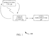
- FIG. 1 illustrates a block diagram of a system 100 for acoustic source localization with aerial drones, in accordance with an example embodiment.
- the system 100 is composed of three units, such as an aerial drone (i.e., a mobile sensing unit 102), a ground control station (GCS) 104, and a cloud infrastructure 106.
- the mobile sensing unit 102 includes a MAV with a wide range of on-board sensors, of which the optical and acoustic cameras are primarily used for external sensing, while other sensors (such as the accelerometer, gyroscope, compass, GPS and altimeter) are used for mission planning and operational maintenance of the unit 102.
- the unit 102 senses physical space, gathers and transfers back raw data to the GCS 104.
- an acoustic camera is a microphone array arranged in a particular geometrical pattern, and is used to determine the location of the sound source.
- Each element of the array is essentially a sensor for receiving the source signal, and its spatial arrangement enables the array to not only sample the wave field in time but also in space.
- the individual signals from each of the array elements are efficiently combined for the purpose of beam forming (or space-time processing).
- the final array response is a beam pattern that has high directivity in a given direction, thereby enabling the isolation, enhancement, suppression or rejection of the acquired signal from certain positions. It also measures the direction-of-arrival (DOA) of the source by correlating the received signal across the different microphone channels.
- DOA direction-of-arrival
- the beam pattern is composed of a main lobe that corresponds to a steering direction and smaller secondary side lobes.
- the ability to resolve sound sources is determined by the width of the main lobe, and its dynamic range is provided by the difference of power levels between the main and side lobes. While side lobes may appear irrelevant, they are a critical measure of the array sensitivity outside the steering direction.
- the preferred beam pattern is the one that suppresses the magnitude of the side lobes, while at the same time maximizes the directivity and resolution of the main lobe with the narrowest beam.
- the main lobe width and side lobe level are usually at odds with each other.
- the array beam pattern is determined by its geometry.
- the main lobe width is inversely proportional to the aperture length A and inter-element spacing B.
- a sparse array design of large aperture is chosen. For example, a sparse array design with only two sensing elements separated by a distance of 23 cm (i.e., 7 ⁇ /2) is chosen.
- AR.Drone 2:0 quadcopter is used as the mobile sensing unit 102.
- this aircraft consists of four propellers units situated in the same horizontal plane located around its body. They provide lift, stability and directional control, and lateral movement to allow the aircraft to propel itself forward in any direction.
- Each propeller unit consists of a 10 cm long blade mounted on a 15 W/28500 revolutions/minute (rpm) brushless motor.
- the GCS 104 is a standard computer that communicates with the mobile sensing unit 102 using a long-range radio.
- the GCS 104 allows the pilot to configure mission parameters.
- the GCS 104 also performs a first-level processing of the sensed data to signal back necessary indicators to the mobile sensing unit 102, as well as acts as an interface to transfer data sent by the mobile sensing unit 102 to the cloud infrastructure 106.
- the cloud infrastructure 106 is a unit where raw data and low-level inferences are permanently stored, curated, processed and fused with archival data for more fine-grained insights.
- the GCS 104 receives a wide band signal associated with an acoustic source from the mobile sensing unit 102 and divides the signal (i.e., a search space) into a grid of a predefined cell size.
- the GCS 104 uses natural mobility of the MAV to beam power to each cell at different measurement locations and at finer frequency resolutions. Subsequently, the GCS 104 consolidates all the beamed power to estimate the source location. This is explained in more detailed with reference to FIG. 2 .
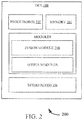
- FIG. 2 illustrates a block diagram of the GCS 104, shown in FIG. 1 , in accordance with an embodiment of the present disclosure.
- the GCS 104 may be embodied in, or is in direct communication with a computing device.
- the GCS 104 includes or is otherwise in communication with one or more hardware processors such as processor(s) 202, one or more memories such as a memory 204, and a network interface unit such as a network interface unit 206.
- the processor 202, memory 204, and the network interface unit 206 may be coupled by a system bus such as a system bus or a similar mechanism.
- FIG. 2 shows example components of the system 200, in other implementations, the system 200 may contain fewer components, additional components, different components, or differently arranged components than depicted in FIG. 2 .
- the processor 202 may include circuitry implementing, among others, audio and logic functions associated with the communication.
- the processor 202 may include, but are not limited to, one or more digital signal processors (DSPs), one or more microprocessor, one or more special-purpose computer chips, one or more field-programmable gate arrays (FPGAs), one or more application-specific integrated circuits (ASICs), one or more computer(s), various analog to digital converters, digital to analog converters, and/or other support circuits.
- the processor 202 thus may also include the functionality to encode messages and/or data or information.
- the processor 202 may include, among other things, a clock, an arithmetic logic unit (ALU) and logic gates configured to support operation of the processor 202. Further, the processor 202 may include functionality to execute one or more software programs, which may be stored in the memory 204 or otherwise accessible to the processor 202.
- DSPs digital signal processors
- FPGAs field-programmable gate arrays
- ASICs application-specific integrated circuits
- processors may be provided through the use of dedicated hardware as well as hardware capable of executing software in association with appropriate software.
- the functions may be provided by a single dedicated processor, by a single shared processor, or by a plurality of individual processors, some of which may be shared.
- explicit use of the term "processor” should not be construed to refer exclusively to hardware capable of executing software, and may implicitly include, without limitation DSP hardware, network processor, application specific integrated circuit (ASIC), FPGA, read only memory (ROM) for storing software, random access memory (RAM), and non-volatile storage. Other hardware, conventional, and/or custom, may also be included.
- the interface(s) 206 may include a variety of software and hardware interfaces, for example, interfaces for peripheral device(s), such as a keyboard, a mouse, an external memory, and a printer.
- the interface(s) 206 can facilitate multiple communications within a wide variety of networks and protocol types, including wired networks, for example, local area network (LAN), cable, etc., and wireless networks, such as Wireless LAN (WLAN), cellular, or satellite.
- LAN local area network
- WLAN Wireless LAN
- cellular or satellite.
- the one or more memories may store any number of pieces of information, and data, used by the system to implement the functions of the system.
- the memory 204 may include for example, volatile memory and/or non-volatile memory. Examples of volatile memory may include, but are not limited to volatile random access memory.
- the non-volatile memory may additionally or alternatively comprise an electrically erasable programmable read only memory (EEPROM), flash memory, hard drive, or the like.
- EEPROM electrically erasable programmable read only memory
- flash memory volatile random access memory
- hard drive or the like.
- Some examples of the volatile memory includes, but are not limited to, random access memory, dynamic random access memory, static random access memory, and the like.
- the non-volatile memory includes, but are not limited to, hard disks, magnetic tapes, optical disks, programmable read only memory, erasable programmable read only memory, electrically erasable programmable read only memory, flash memory, and the like.
- the memory 204 may be configured to store information, data, applications, instructions or the like for enabling the system 200 to carry out various functions in accordance with various example embodiments. Additionally or alternatively, the memory 204 may be configured to store instructions which when executed by the processor 202 causes the system to behave in a manner as described in various embodiments.
- the memory 204 includes a fusion module 208 and other modules.
- the module 208 and other modules include routines, programs, objects, components, data structures, etc., which perform particular tasks or implement particular abstract data types.
- the other modules may include programs or coded instructions that supplement applications and functions of the system 200.
- the fusion module 208 receives a wideband acoustic signal from the aerial drone 102.
- the fusion module 208 splits the wideband acoustic signal into multiple narrow sub-bands having cells.
- the signal received at each channel is decomposed into smaller sub-bands using a filter bank comprising of Ns non-overlapping filters.
- s q (i) (t) represents the i th sub-band of the q th source
- a l (i) (p q ) denotes the array response at the l th measurement location for the i th sub-band for the signal source located at p q
- r l i (t) is a M X 1 vector.
- the ULA supported beam former given by equation (3) is subject to spatial aliasing at higher frequency sub-bands.
- ⁇ l ( i ) [ a l ( i ) ( p ⁇ 1 ), a l ( i ) ( p ⁇ 2 ) , ... ... ... ... ..., al ( i ) ( p ⁇ N p )] and is of size M X N p .
- the k th row of the sparse vector s ⁇ l ( i ) is non-zero and is equal to s k ( i ) ( t ) if a source signal is present at location p k .
- the equation (4) is for the measurement at one single location 1 and one sub-band i.
- the fusion module 208 From a measurement position corresponding to each of the multiple narrow sub-bands, the fusion module 208 the measures power in each of the cells by forming a beam to each of the cells. Furthermore, the fusion module 208 performs intra-band and inter measurement fusion of the measured power at each of the cells. In an embodiment, the fusion module 208 fuses the measured power of each of the cells at a measurement position across the multiple narrow sub-bands. In an example implementation, the fusion module 208 fuses the measured power of each of the cells at the measurement position having a common look-ahead direction across the all narrow sub-bands.
- the fusion module 208 then fuses the measured power of each of the cells across the measurement positions upon fusing the measured power of each of the cells at the measurement position across the multiple narrow sub-bands.
- the power in each of the cells is determined by beam forming and appropriately fusing the individual power measurements in a manner such that the power in the respective cell where the target signal is present is boosted up compared to other empty cells.
- the beam corresponding to lower sub-bands yield a single beam but of wider width (beams corresponding to 500 Hz (single beam at 0°, but of wider width) is shown in a graph 300A of FIG. 3A ) while the beam corresponding to higher sub-bands (i.e., higher frequencies) yields a narrower beam, but consists of undesirable grating lobes (beams corresponding to 5 kHz (a narrow beam, but with grating lobes at 180° that spreads into -90° and +90°) is shown in a graph 300B of FIG. 3B ).
- the fusion module 208 identifies geo-location of an acoustic source corresponding to the wideband acoustic signal upon performing intra-band and inter measurement fusion of the measured power. For example, the module 208 identifies one of the cells having maximum power is identified as the geo-location of the acoustic source. For example, a speaker symbol in graphs 400A-D of FIGS. 4A-D denotes an original location of a sound source and a red blob in a graph 400E of FIG. 4E represents its estimated location.
- FIG. 5 illustrates a flow diagram of a method 500 for acoustic source localization with aerial drones, in accordance with an example embodiment.
- the method 500 may be described in the general context of computer executable instructions.
- computer executable instructions can include routines, programs, objects, components, data structures, procedures, modules, functions, etc., that perform particular functions or implement particular abstract data types.
- the method 500 may also be practiced in a distributed computing environment where functions are performed by remote processing devices that are linked through a communication network.
- the order in which the method 500 is described is not intended to be construed as a limitation, and any number of the described method blocks can be combined in any order to implement the method 500, or an alternative method.
- the method 500 can be implemented in any suitable hardware, software, firmware, or combination thereof.
- the method 500 depicted in the flow chart may be executed by a system, for example, the system 100 of FIG. 1 .
- a wideband acoustic signal is received from an aerial drone.
- the wideband acoustic signal is splitted into multiple narrow sub-bands having cells.
- the wideband acoustic signal is splitted into the multiple narrow sub-bands using N-channel filter bank.
- intra-band and inter measurement fusion of the measured power is performed at each of the cells.
- the measured power of each of the cells is fused at a measurement position across the multiple narrow sub-bands.
- the measured power of each of the cells is fused at the measurement position having a common look-ahead direction across the multiple narrow sub-bands. Further, the measured power of each of the cells is fused across the measurement positions upon fusing the measured power of each of the cells at the measurement position across the multiple narrow sub-bands.
- geo-location of an acoustic source corresponding to the wideband acoustic signal is identified upon performing intra-band and inter measurement fusion of the measured power.
- one of the cells having maximum power is identified upon performing intra-band and inter measurement fusion of the measured power as the geo-location of the acoustic source.
- non-transitory computer-readable storage means contain program-code means for implementation of one or more steps of the method, when the program runs on a server or mobile device or any suitable programmable device.
- the hardware device can be any kind of device which can be programmed including e.g. any kind of computer like a server or a personal computer, or the like, or any combination thereof.
- the device may also include means which could be e.g. hardware means like e.g. an application-specific integrated circuit (ASIC), a field-programmable gate array (FPGA), or a combination of hardware and software means, e.g.
- ASIC application-specific integrated circuit
- FPGA field-programmable gate array
- the means can include both hardware means and software means.
- the method embodiments described herein could be implemented in hardware and software.
- the device may also include software means.
- the embodiments may be implemented on different hardware devices, e.g. using a plurality of CPUs.
- the embodiments herein can comprise hardware and software elements.
- the embodiments that are implemented in software include but are not limited to, firmware, resident software, microcode, etc.
- the functions performed by various modules described herein may be implemented in other modules or combinations of other modules.
- a computer-usable or computer readable medium can be any apparatus that can comprise, store, communicate, propagate, or transport the program for use by or in connection with the instruction execution system, apparatus, or device.
Landscapes
- Engineering & Computer Science (AREA)
- Physics & Mathematics (AREA)
- General Physics & Mathematics (AREA)
- Radar, Positioning & Navigation (AREA)
- Remote Sensing (AREA)
- Acoustics & Sound (AREA)
- Signal Processing (AREA)
- Measurement Of Velocity Or Position Using Acoustic Or Ultrasonic Waves (AREA)
- Aviation & Aerospace Engineering (AREA)
Abstract
Description
- The present application claims priority to Indian Patent Application No.
201721026912, filed on July 28, 2017 - The embodiments herein generally relate to source localization, and, more particularly, to system and method for acoustic source localization with aerial drones.
- Aerial drones, especially the micro, multi-rotor class with hovering capability, are fast emerging as a powerful new class of mobile sensing systems with a rich sensory gamut neatly combined with on-board communication and computing elements, and mobile agility regardless of the terrain and space (indoor/outdoor) constraints. They, also referred to as micro aerial vehicles (MAVs) are increasingly finding their usage across a wide range of applications ranging from industrial (e.g., infrastructure inspection of near-inaccessible areas such as civil structure or machinery/asset at high elevation, utility pipeline or overhead cable inspection over very long distances, etc.,) to humanitarian (e.g., search and rescue, emergency response, etc.,) sectors.
- Vision is the most prominent mode of sensing in MAVs. Compared to other spatially rich sensors such as sonar and laser range finders (that are commonly used in terrestrial vehicles), vision sensors require comparatively lower energy to interrogate the environment and for a comparable mass, they can gather richer information and span wider fields of view. However, the MAVs become unusable in camera obstructed, occluded, low-light conditions, or in scenarios that offer profound non-visual clues (such as auditory acoustics).
- The following presents a simplified summary of some embodiments of the disclosure in order to provide a basic understanding of the embodiments. This summary is not an extensive overview of the embodiments. It is not intended to identify key/critical elements of the embodiments or to delineate the scope of the embodiments. Its sole purpose is to present some embodiments in a simplified form as a prelude to the more detailed description that is presented below.
- In view of the foregoing, an embodiment herein provides methods and systems for acoustic source localization with aerial drones. In one aspect, a processor-implemented method includes steps of: receiving, by one or more hardware processors, a wideband acoustic signal from an aerial drone; splitting, by the one or more hardware processors, the wideband acoustic signal into multiple narrow sub-bands having cells; from a measurement position corresponding to each of the multiple narrow sub-bands, measuring, by the one or more hardware processors, power in each of the cells by forming a beam at each of the cells; performing, by the one or more hardware processors, intra-band and inter measurement fusion of the measured power at each of the cells; and identifying, by the one or more hardware processors, geo-location of an acoustic source corresponding to the wideband acoustic signal upon performing intra-band and inter measurement fusion of the measured power.
- In another aspect, a system for acoustic source localization with aerial drones is provided. The system includes an aerial drone to receive a wideband acoustic signal from a source. Further, the system includes a global control unit communicatively coupled to the aerial drone. In an embodiment, the global control unit includes one or more memories; and one or more hardware processors, the one or more memories coupled to the one or more hardware processors wherein the one or more hardware processors are configured to execute programmed instructions stored in the one or more memories to: receive the wideband acoustic signal from the aerial drone; split the wideband acoustic signal into multiple narrow sub-bands having cells; from a measurement position corresponding to each of the multiple narrow sub-bands, measure power in each of the cells by forming a beam at each of the cells; perform intra-band and inter measurement fusion of the measured power at each of the cells; and identify geo-location of an acoustic source corresponding to the wideband acoustic signal upon performing intra-band and inter measurement fusion of the measured power.
- In yet another aspect, a non-transitory computer-readable medium having embodied thereon a computer program for executing a method for acoustic source localization with aerial drones is provided. The method includes the steps of: receiving, by one or more hardware processors, a wideband acoustic signal from an aerial drone; splitting, by the one or more hardware processors, the wideband acoustic signal into multiple narrow sub-bands having cells; from a measurement position corresponding to each of the multiple narrow sub-bands, measuring, by the one or more hardware processors, power in each of the cells by forming a beam at each of the cells; performing, by the one or more hardware processors, intra-band and inter measurement fusion of the measured power at each of the cells; and identifying, by the one or more hardware processors, geo-location of an acoustic source corresponding to the wideband acoustic signal upon performing intra-band and inter measurement fusion of the measured power..
- It should be appreciated by those skilled in the art that any block diagram herein represents conceptual views of illustrative systems embodying the principles of the present subject matter. Similarly, it is appreciated that any flow charts, flow diagrams, state transition diagrams, pseudo code, and the like represent various processes which may be substantially represented in computer readable medium and so executed by a computing device or processor, whether or not such computing device or processor is explicitly shown.
- The detailed description is described with reference to the accompanying figures. In the figures, the left-most digit(s) of a reference number identifies the figure in which the reference number first appears. The same numbers are used throughout the drawings to reference like features and modules.
-
FIG. 1 illustrates a block diagram of a system for acoustic source localization with aerial drones, in accordance with an example embodiment. -
FIG. 2 illustrates a block diagram of a ground station controller shown inFIG. 1 , in accordance with an example embodiment. -
FIG. 3 illustrates rationale of intra-band beam fusion, in accordance with an example embodiment. -
FIGS. 4A-4D are graphs illustrating an original location of a sound source, in accordance with an example embodiment. -
FIG. 4E is a graph illustrating an estimated location of the sound source, in accordance with an example embodiment. -
FIG. 5 illustrates a flow diagram of a method for acoustic source localization with aerial drones, in accordance with an example embodiment. - It should be appreciated by those skilled in the art that any block diagrams herein represent conceptual views of illustrative systems and devices embodying the principles of the present subject matter. Similarly, it will be appreciated that any flow charts, flow diagrams, and the like represent various processes which may be substantially represented in computer readable medium and so executed by a computer or processor, whether or not such computer or processor is explicitly shown.
- The embodiments herein and the various features and advantageous details thereof are explained more fully with reference to the non-limiting embodiments that are illustrated in the accompanying drawings and detailed in the following description. The examples used herein are intended merely to facilitate an understanding of ways in which the embodiments herein may be practiced and to further enable those of skill in the art to practice the embodiments herein. Accordingly, the examples should not be construed as limiting the scope of the embodiments herein.
- A robust acoustic localization technique for detecting sound sources in a physical space-of-interest is disclosed. Devising this capability is extremely challenging due to strong ego-noise from micro aerial vehicles (MAVs)' propeller units, which is both wideband and non-stationary. The present subject matter discloses a system for geo-locating sound sources in the presence of strong, wideband, non-stationary ego-noise of the mobile platform. It combines the benefits of sparse (two elements) sensor array design (for meeting the platform constraints), and mobility induced beam forming based on intra-band and inter-measurement beam fusion (for overcoming the severe ego-noise and its other complex characteristics) to significantly enhance the received signal-to-noise ratio (SNR). It provides a signal to noise ration (SNR) improvement of 15 to 18 dB compared to many conventional and widely used known methods. This SNR gain translates to a location accuracy of approximately 40 cm within a scan region of 6m X 3m.
- The methods and systems are not limited to the specific embodiments described herein. In addition, the method and system can be practiced independently and separately from other modules and methods described herein. Each device element/module and method can be used in combination with other elements/modules and other methods.
- The manner, in which the system and method for acoustic source localization with aerial drones, has been explained in details with respect to the
FIGS. 1 through 5 . While aspects of described methods and systems for acoustic source localization with aerial drones can be implemented in any number of different systems, utility environments, and/or configurations, the embodiments are described in the context of the following exemplary system(s). -
FIG. 1 illustrates a block diagram of asystem 100 for acoustic source localization with aerial drones, in accordance with an example embodiment. As shown inFIG. 1 , thesystem 100 is composed of three units, such as an aerial drone (i.e., a mobile sensing unit 102), a ground control station (GCS) 104, and acloud infrastructure 106. For example, themobile sensing unit 102 includes a MAV with a wide range of on-board sensors, of which the optical and acoustic cameras are primarily used for external sensing, while other sensors (such as the accelerometer, gyroscope, compass, GPS and altimeter) are used for mission planning and operational maintenance of theunit 102. Theunit 102 senses physical space, gathers and transfers back raw data to theGCS 104. - For example, an acoustic camera is a microphone array arranged in a particular geometrical pattern, and is used to determine the location of the sound source. Each element of the array is essentially a sensor for receiving the source signal, and its spatial arrangement enables the array to not only sample the wave field in time but also in space. The individual signals from each of the array elements are efficiently combined for the purpose of beam forming (or space-time processing). The final array response is a beam pattern that has high directivity in a given direction, thereby enabling the isolation, enhancement, suppression or rejection of the acquired signal from certain positions. It also measures the direction-of-arrival (DOA) of the source by correlating the received signal across the different microphone channels. Thus, the beam pattern of an array is the key element that determines its performance. For example, the beam pattern is composed of a main lobe that corresponds to a steering direction and smaller secondary side lobes. The ability to resolve sound sources is determined by the width of the main lobe, and its dynamic range is provided by the difference of power levels between the main and side lobes. While side lobes may appear irrelevant, they are a critical measure of the array sensitivity outside the steering direction. The preferred beam pattern is the one that suppresses the magnitude of the side lobes, while at the same time maximizes the directivity and resolution of the main lobe with the narrowest beam. The main lobe width and side lobe level are usually at odds with each other. It is observed that lowering the side lobes leads to an increase in the width of the main lobe, and finding an optimal beam pattern involves a compromise between the two ends. The array beam pattern is determined by its geometry. The main lobe width is inversely proportional to the aperture length A and inter-element spacing B. In order to strike a good balance between array efficiency and the platform constraints of minimal payload and operation overhead, a sparse array design of large aperture is chosen. For example, a sparse array design with only two sensing elements separated by a distance of 23 cm (i.e., 7λ/2) is chosen.
- In an example implementation, AR.Drone 2:0 quadcopter is used as the
mobile sensing unit 102. As the name quadcopter implies, this aircraft consists of four propellers units situated in the same horizontal plane located around its body. They provide lift, stability and directional control, and lateral movement to allow the aircraft to propel itself forward in any direction. Each propeller unit consists of a 10 cm long blade mounted on a 15 W/28500 revolutions/minute (rpm) brushless motor. - Further, the
GCS 104 is a standard computer that communicates with themobile sensing unit 102 using a long-range radio. TheGCS 104 allows the pilot to configure mission parameters. TheGCS 104 also performs a first-level processing of the sensed data to signal back necessary indicators to themobile sensing unit 102, as well as acts as an interface to transfer data sent by themobile sensing unit 102 to thecloud infrastructure 106. Thecloud infrastructure 106 is a unit where raw data and low-level inferences are permanently stored, curated, processed and fused with archival data for more fine-grained insights. - In operation, the
GCS 104 receives a wide band signal associated with an acoustic source from themobile sensing unit 102 and divides the signal (i.e., a search space) into a grid of a predefined cell size. TheGCS 104 then uses natural mobility of the MAV to beam power to each cell at different measurement locations and at finer frequency resolutions. Subsequently, theGCS 104 consolidates all the beamed power to estimate the source location. This is explained in more detailed with reference toFIG. 2 . -
FIG. 2 illustrates a block diagram of theGCS 104, shown inFIG. 1 , in accordance with an embodiment of the present disclosure. In an example embodiment, theGCS 104 may be embodied in, or is in direct communication with a computing device. TheGCS 104 includes or is otherwise in communication with one or more hardware processors such as processor(s) 202, one or more memories such as amemory 204, and a network interface unit such as anetwork interface unit 206. In an embodiment, theprocessor 202,memory 204, and thenetwork interface unit 206 may be coupled by a system bus such as a system bus or a similar mechanism. AlthoughFIG. 2 shows example components of thesystem 200, in other implementations, thesystem 200 may contain fewer components, additional components, different components, or differently arranged components than depicted inFIG. 2 . - The
processor 202 may include circuitry implementing, among others, audio and logic functions associated with the communication. For example, theprocessor 202 may include, but are not limited to, one or more digital signal processors (DSPs), one or more microprocessor, one or more special-purpose computer chips, one or more field-programmable gate arrays (FPGAs), one or more application-specific integrated circuits (ASICs), one or more computer(s), various analog to digital converters, digital to analog converters, and/or other support circuits. Theprocessor 202 thus may also include the functionality to encode messages and/or data or information. Theprocessor 202 may include, among other things, a clock, an arithmetic logic unit (ALU) and logic gates configured to support operation of theprocessor 202. Further, theprocessor 202 may include functionality to execute one or more software programs, which may be stored in thememory 204 or otherwise accessible to theprocessor 202. - The functions of the various elements shown in the figure, including any functional blocks labeled as "processor(s)", may be provided through the use of dedicated hardware as well as hardware capable of executing software in association with appropriate software. When provided by a processor, the functions may be provided by a single dedicated processor, by a single shared processor, or by a plurality of individual processors, some of which may be shared. Moreover, explicit use of the term "processor" should not be construed to refer exclusively to hardware capable of executing software, and may implicitly include, without limitation DSP hardware, network processor, application specific integrated circuit (ASIC), FPGA, read only memory (ROM) for storing software, random access memory (RAM), and non-volatile storage. Other hardware, conventional, and/or custom, may also be included.
- The interface(s) 206 may include a variety of software and hardware interfaces, for example, interfaces for peripheral device(s), such as a keyboard, a mouse, an external memory, and a printer. The interface(s) 206 can facilitate multiple communications within a wide variety of networks and protocol types, including wired networks, for example, local area network (LAN), cable, etc., and wireless networks, such as Wireless LAN (WLAN), cellular, or satellite.
- The one or more memories such as a
memory 204, may store any number of pieces of information, and data, used by the system to implement the functions of the system. Thememory 204 may include for example, volatile memory and/or non-volatile memory. Examples of volatile memory may include, but are not limited to volatile random access memory. The non-volatile memory may additionally or alternatively comprise an electrically erasable programmable read only memory (EEPROM), flash memory, hard drive, or the like. Some examples of the volatile memory includes, but are not limited to, random access memory, dynamic random access memory, static random access memory, and the like. Some example of the non-volatile memory includes, but are not limited to, hard disks, magnetic tapes, optical disks, programmable read only memory, erasable programmable read only memory, electrically erasable programmable read only memory, flash memory, and the like. Thememory 204 may be configured to store information, data, applications, instructions or the like for enabling thesystem 200 to carry out various functions in accordance with various example embodiments. Additionally or alternatively, thememory 204 may be configured to store instructions which when executed by theprocessor 202 causes the system to behave in a manner as described in various embodiments. Thememory 204 includes a fusion module 208 and other modules. The module 208 and other modules include routines, programs, objects, components, data structures, etc., which perform particular tasks or implement particular abstract data types. The other modules may include programs or coded instructions that supplement applications and functions of thesystem 200. - In operation, the fusion module 208 receives a wideband acoustic signal from the
aerial drone 102. In an example implementation, a uniform linear array (ULA) comprising of M channels indexed by m = {1, 2... M } and equally spaced on a line with an inter-element distance of B is considered. It is mounted on the MAV, and receives signals radiated by Q wideband stationary sound sources. The sources are located in the far field. For example, D × 1 position of the qth transmitter is denoted as pq. Since ULA can only resolve sources in 2D, D = 2 in this example. The MAV is supposed to take measurements at the lth position for a total of L different locations, where l = {1, 2... L}. The complex signal envelope observed by the mth sensor element at the lth position is expressed as:
- Further the fusion module 208 splits the wideband acoustic signal into multiple narrow sub-bands having cells. For wideband processing, the signal received at each channel is decomposed into smaller sub-bands using a filter bank comprising of Ns non-overlapping filters. Using equation 1 and a standard narrowband signal, the signal observed at the ith measurement position corresponding to the ith sub-band can be expressed as:


- Further, the ULA supported beam former given by equation (3) is subject to spatial aliasing at higher frequency sub-bands. In sparse representation framework, the locations of the smaller cells in the scan region are denoted by


p )] and is of size M X Np. In this representation, the kth row of the sparse vector s̃l (i) is non-zero and is equal to sk (i)(t) if a source signal is present at location pk. Also, the equation (4) is for the measurement at one single location 1 and one sub-band i. - From a measurement position corresponding to each of the multiple narrow sub-bands, the fusion module 208 the measures power in each of the cells by forming a beam to each of the cells. Furthermore, the fusion module 208 performs intra-band and inter measurement fusion of the measured power at each of the cells. In an embodiment, the fusion module 208 fuses the measured power of each of the cells at a measurement position across the multiple narrow sub-bands. In an example implementation, the fusion module 208 fuses the measured power of each of the cells at the measurement position having a common look-ahead direction across the all narrow sub-bands. The fusion module 208 then fuses the measured power of each of the cells across the measurement positions upon fusing the measured power of each of the cells at the measurement position across the multiple narrow sub-bands. In other words, the power in each of the cells is determined by beam forming and appropriately fusing the individual power measurements in a manner such that the power in the respective cell where the target signal is present is boosted up compared to other empty cells. In an example, the combined intra-band and inter-measurement fused power for a cell located at P̃ k is estimated using the following expression:


- In this embodiment, the beam corresponding to lower sub-bands (i.e., lower frequencies) yield a single beam but of wider width (beams corresponding to 500 Hz (single beam at 0°, but of wider width) is shown in a
graph 300A ofFIG. 3A ) while the beam corresponding to higher sub-bands (i.e., higher frequencies) yields a narrower beam, but consists of undesirable grating lobes (beams corresponding to 5 kHz (a narrow beam, but with grating lobes at 180° that spreads into -90° and +90°) is shown in agraph 300B ofFIG. 3B ). By fusing the beams of all sub-bands (performing the Π operation of the equation 5), a relatively narrow beam is obtained and significant reduction is obtained in grating lobes levels (as shown in agraph 300C ofFIG. 3C ). Thereafter, the inter-measurement fusion across all measurement location is performed by the Σ operation of the equation 5. The power in that corresponding cell where the actual sound source is located eventually increases (as a result of this aggregation) than the beam forming power corresponding to individual measurement location, with significant reduction in the power levels of the unwanted grating lobes and noisy peaks. Thus, it not only overcomes spatial aliasing, but also improves the performance in estimating the location of the sound source(s) in a processing step. - In addition, the fusion module 208 identifies geo-location of an acoustic source corresponding to the wideband acoustic signal upon performing intra-band and inter measurement fusion of the measured power. For example, the module 208 identifies one of the cells having maximum power is identified as the geo-location of the acoustic source. For example, a speaker symbol in
graphs 400A-D ofFIGS. 4A-D denotes an original location of a sound source and a red blob in agraph 400E ofFIG. 4E represents its estimated location. -
FIG. 5 illustrates a flow diagram of amethod 500 for acoustic source localization with aerial drones, in accordance with an example embodiment. Themethod 500 may be described in the general context of computer executable instructions. Generally, computer executable instructions can include routines, programs, objects, components, data structures, procedures, modules, functions, etc., that perform particular functions or implement particular abstract data types. Themethod 500 may also be practiced in a distributed computing environment where functions are performed by remote processing devices that are linked through a communication network. The order in which themethod 500 is described is not intended to be construed as a limitation, and any number of the described method blocks can be combined in any order to implement themethod 500, or an alternative method. Furthermore, themethod 500 can be implemented in any suitable hardware, software, firmware, or combination thereof. In an embodiment, themethod 500 depicted in the flow chart may be executed by a system, for example, thesystem 100 ofFIG. 1 . - At
block 502, a wideband acoustic signal is received from an aerial drone. Atblock 504, the wideband acoustic signal is splitted into multiple narrow sub-bands having cells. In an embodiment, the wideband acoustic signal is splitted into the multiple narrow sub-bands using N-channel filter bank. Atblock 506, form a measurement position corresponding to each of the multiple narrow sub-bands, power in each of the cells is measured by forming a beam to each of the cells. - At
block 508, intra-band and inter measurement fusion of the measured power is performed at each of the cells. In an example implementation, the measured power of each of the cells is fused at a measurement position across the multiple narrow sub-bands. In an example, the measured power of each of the cells is fused at the measurement position having a common look-ahead direction across the multiple narrow sub-bands. Further, the measured power of each of the cells is fused across the measurement positions upon fusing the measured power of each of the cells at the measurement position across the multiple narrow sub-bands. - At block 510, geo-location of an acoustic source corresponding to the wideband acoustic signal is identified upon performing intra-band and inter measurement fusion of the measured power. In an example implementation, one of the cells having maximum power is identified upon performing intra-band and inter measurement fusion of the measured power as the geo-location of the acoustic source.
- The written description describes the subject matter herein to enable any person skilled in the art to make and use the embodiments. The scope of the subject matter embodiments is defined by the claims and may include other modifications that occur to those skilled in the art. Such other modifications are intended to be within the scope of the claims if they have similar elements that do not differ from the literal language of the claims or if they include equivalent elements with insubstantial differences from the literal language of the claims.
- It is, however to be understood that the scope of the protection is extended to such a program and in addition to a computer-readable means having a message therein; such non-transitory computer-readable storage means contain program-code means for implementation of one or more steps of the method, when the program runs on a server or mobile device or any suitable programmable device. The hardware device can be any kind of device which can be programmed including e.g. any kind of computer like a server or a personal computer, or the like, or any combination thereof. The device may also include means which could be e.g. hardware means like e.g. an application-specific integrated circuit (ASIC), a field-programmable gate array (FPGA), or a combination of hardware and software means, e.g. an ASIC and an FPGA, or at least one microprocessor and at least one memory with software modules located therein. Thus, the means can include both hardware means and software means. The method embodiments described herein could be implemented in hardware and software. The device may also include software means. Alternatively, the embodiments may be implemented on different hardware devices, e.g. using a plurality of CPUs.
- The embodiments herein can comprise hardware and software elements. The embodiments that are implemented in software include but are not limited to, firmware, resident software, microcode, etc. The functions performed by various modules described herein may be implemented in other modules or combinations of other modules. For the purposes of this description, a computer-usable or computer readable medium can be any apparatus that can comprise, store, communicate, propagate, or transport the program for use by or in connection with the instruction execution system, apparatus, or device.
- The foregoing description of the specific implementations and embodiments will so fully reveal the general nature of the implementations and embodiments herein that others can, by applying current knowledge, readily modify and/or adapt for various applications such specific embodiments without departing from the generic concept, and, therefore, such adaptations and modifications should and are intended to be comprehended within the meaning and range of equivalents of the disclosed embodiments. It is to be understood that the phraseology or terminology employed herein is for the purpose of description and not of limitation. Therefore, while the embodiments herein have been described in terms of preferred embodiments, those skilled in the art will recognize that the embodiments herein can be practiced with modification within the spirit and scope of the embodiments as described herein.
- The preceding description has been presented with reference to various embodiments. Persons having ordinary skill in the art and technology to which this application pertains will appreciate that alterations and changes in the described structures and methods of operation can be practiced without meaningfully departing from the principle, spirit and scope.
Claims (11)
- A processor-implemented method comprising:receiving, by one or more hardware processors, a wideband acoustic signal from an aerial drone;splitting, by the one or more hardware processors, the wideband acoustic signal into multiple narrow sub-bands having cells;from a measurement position corresponding to each of the multiple narrow sub-bands, measuring, by the one or more hardware processors, power in each of the cells by forming a beam to each of the cells;performing, by the one or more hardware processors, intra-band and inter measurement fusion of the measured power at each of the cells; andidentifying, by the one or more hardware processors, geo-location of an acoustic source corresponding to the wideband acoustic signal upon performing intra-band and inter measurement fusion of the measured power.
- The method according to claim 1, wherein splitting the wideband acoustic signal into multiple narrow sub-bands, comprises:
splitting the wideband acoustic signal into the multiple narrow sub-bands using N-channel filter bank. - The method according to claim 1, wherein performing intra-band and inter measurement fusion of the measured power at each of the cells, comprises:fusing the measured power of each of the cells at a measurement position across the multiple narrow sub-bands; andfusing the measured power of each of the cells across the measurement positions upon fusing the measured power of each of the cells at the measurement position across the multiple narrow sub-bands.
- The method according to claim 3, wherein fusing the measured power of each of the cells at the measurement position across the multiple narrow sub-bands, comprises:
fusing the measured power of each of the cells at the measurement position having a common look-ahead direction across the multiple narrow sub-bands. - The method according to claim 1, wherein identifying geo-location of the acoustic source corresponding to the wideband acoustic signal upon performing intra-band and inter measurement fusion of the measured power, comprises:
identifying one of the cells having maximum power upon performing intra-band and inter measurement fusion of the measured power as the geo-location of the acoustic source. - A system comprising:an aerial drone, wherein the aerial drone captures a wideband acoustic signal from a source; anda ground control unit communicatively coupled to the aerial drone; wherein the ground control unit comprises:one or more memories; andone or more hardware processors, the one or more memories coupled to the one or more hardware processors, wherein the one or more hardware processors are configured to execute programmed instructions stored in the one or more memories to:receive the wideband acoustic signal from the aerial drone;split the wideband acoustic signal into multiple narrow sub-bands having cells;from a measurement position corresponding to each of the multiple narrow sub-bands, measure power in each of the cells by forming a beam at each of the cells;perform intra-band and inter measurement fusion of the measured power at each of the cells; andidentify geo-location of an acoustic source corresponding to the wideband acoustic signal upon performing intra-band and inter measurement fusion of the measured power.
- The system according to claim 6, wherein the one or more hardware processors are further capable of executing programmed instructions to:
split the wideband acoustic signal into the multiple narrow sub-bands using N-channel filter bank. - The system according to claim 6, wherein the one or more hardware processors are further capable of executing programmed instructions to:fuse the measured power of each of the cells at a measurement position across the multiple narrow sub-bands; andfuse the measured power of each of the cells across the measurement positions upon fusing the measured power of each of the cells at the measurement position across the multiple narrow sub-bands.
- The system according to claim 8, wherein the one or more hardware processors are further capable of executing programmed instructions to:
fuse the measured power of each of the cells at the measurement position having a common look-ahead direction across the multiple narrow sub-bands. - The system according to claim 6, wherein the one or more hardware processors are further capable of executing programmed instructions to:
identifying one of the cells having maximum power upon performing intra-band and inter measurement fusion of the measured power as the geo-location of the acoustic source. - A non-transitory computer readable medium embodying a program executable in a computing device, the program comprising:a program code for receiving a wideband acoustic signal from an aerial drone;a program code for splitting the wideband acoustic signal into multiple narrow sub-bands having cells;a program code for, from a measurement position corresponding to each of the multiple narrow sub-bands, measuring power in each of the cells by forming a beam to each of the cells;a program code for performing intra-band and inter measurement fusion of the measured power at each of the cells; anda program code for identifying geo-location of an acoustic source corresponding to the wideband acoustic signal upon performing intra-band and inter measurement fusion of the measured power.
Applications Claiming Priority (1)
| Application Number | Priority Date | Filing Date | Title |
|---|---|---|---|
| IN201721026912 | 2017-07-28 |
Publications (2)
| Publication Number | Publication Date |
|---|---|
| EP3435110A1 true EP3435110A1 (en) | 2019-01-30 |
| EP3435110B1 EP3435110B1 (en) | 2020-05-13 |
Family
ID=61750041
Family Applications (1)
| Application Number | Title | Priority Date | Filing Date |
|---|---|---|---|
| EP18163346.2A Active EP3435110B1 (en) | 2017-07-28 | 2018-03-22 | System and method for acoustic source localization with aerial drones |
Country Status (2)
| Country | Link |
|---|---|
| US (1) | US10739435B2 (en) |
| EP (1) | EP3435110B1 (en) |
Cited By (4)
| Publication number | Priority date | Publication date | Assignee | Title |
|---|---|---|---|---|
| US10739435B2 (en) * | 2017-07-28 | 2020-08-11 | Tata Consultancy Services Limited | System method for acoustic source localization with aerial drones |
| IT201900017423A1 (en) * | 2019-09-27 | 2021-03-27 | Earfly Sagl | DRONE FOR RESEARCH AND ASSOCIATED RESEARCH METHOD |
| US11115108B2 (en) * | 2019-10-25 | 2021-09-07 | Tata Consultancy Services Limited | Method and system for field agnostic source localization |
| PL448778A1 (en) * | 2024-06-07 | 2025-12-08 | Politechnika Wrocławska | Device for locating noise sources and diagnosing industrial infrastructure |
Families Citing this family (2)
| Publication number | Priority date | Publication date | Assignee | Title |
|---|---|---|---|---|
| CN110082712B (en) * | 2019-03-14 | 2022-12-13 | 哈尔滨工程大学 | A Method for Estimating Azimuth of Coherent Target with Acoustic Vector Circular Array |
| KR20240051201A (en) | 2021-09-30 | 2024-04-19 | 제이에프이 어드밴테크 가부시키가이샤 | Sound wave receiving device, sound source direction expression device, and sound source direction expression method |
Citations (1)
| Publication number | Priority date | Publication date | Assignee | Title |
|---|---|---|---|---|
| US6424596B1 (en) * | 2001-10-01 | 2002-07-23 | The United States Of America As Represented By The Secretary Of The Navy | Method and apparatus for reducing noise from near ocean surface sources |
Family Cites Families (4)
| Publication number | Priority date | Publication date | Assignee | Title |
|---|---|---|---|---|
| US7551519B2 (en) | 2006-12-21 | 2009-06-23 | Dan Slater | Passive long range acoustic sensor |
| EP3712635A1 (en) | 2014-08-29 | 2020-09-23 | SZ DJI Technology Co., Ltd. | An unmanned aerial vehicle (uav) for collecting audio data |
| US9571180B2 (en) | 2014-10-16 | 2017-02-14 | Ubiqomm Llc | Unmanned aerial vehicle (UAV) beam forming and pointing toward ground coverage area cells for broadband access |
| EP3435110B1 (en) * | 2017-07-28 | 2020-05-13 | Tata Consultancy Services Limited | System and method for acoustic source localization with aerial drones |
-
2018
- 2018-03-22 EP EP18163346.2A patent/EP3435110B1/en active Active
- 2018-03-27 US US15/937,597 patent/US10739435B2/en active Active
Patent Citations (1)
| Publication number | Priority date | Publication date | Assignee | Title |
|---|---|---|---|---|
| US6424596B1 (en) * | 2001-10-01 | 2002-07-23 | The United States Of America As Represented By The Secretary Of The Navy | Method and apparatus for reducing noise from near ocean surface sources |
Non-Patent Citations (2)
| Title |
|---|
| KEITA OKUTANI ET AL: "Outdoor auditory scene analysis using a moving microphone array embedded in a quadrocopter", INTELLIGENT ROBOTS AND SYSTEMS (IROS), 2012 IEEE/RSJ INTERNATIONAL CONFERENCE ON, IEEE, 7 October 2012 (2012-10-07), pages 3288 - 3293, XP032287840, ISBN: 978-1-4673-1737-5, DOI: 10.1109/IROS.2012.6385994 * |
| WANG LIN ET AL: "Microphone-Array Ego-Noise Reduction Algorithms for Auditory Micro Aerial Vehicles", IEEE SENSORS JOURNAL, IEEE SERVICE CENTER, NEW YORK, NY, US, vol. 17, no. 8, 15 April 2017 (2017-04-15), pages 2447 - 2455, XP011643679, ISSN: 1530-437X, [retrieved on 20170322], DOI: 10.1109/JSEN.2017.2669262 * |
Cited By (4)
| Publication number | Priority date | Publication date | Assignee | Title |
|---|---|---|---|---|
| US10739435B2 (en) * | 2017-07-28 | 2020-08-11 | Tata Consultancy Services Limited | System method for acoustic source localization with aerial drones |
| IT201900017423A1 (en) * | 2019-09-27 | 2021-03-27 | Earfly Sagl | DRONE FOR RESEARCH AND ASSOCIATED RESEARCH METHOD |
| US11115108B2 (en) * | 2019-10-25 | 2021-09-07 | Tata Consultancy Services Limited | Method and system for field agnostic source localization |
| PL448778A1 (en) * | 2024-06-07 | 2025-12-08 | Politechnika Wrocławska | Device for locating noise sources and diagnosing industrial infrastructure |
Also Published As
| Publication number | Publication date |
|---|---|
| US10739435B2 (en) | 2020-08-11 |
| US20190033422A1 (en) | 2019-01-31 |
| EP3435110B1 (en) | 2020-05-13 |
Similar Documents
| Publication | Publication Date | Title |
|---|---|---|
| US10739435B2 (en) | System method for acoustic source localization with aerial drones | |
| US20180032042A1 (en) | System And Method Of Dynamically Controlling Parameters For Processing Sensor Output Data | |
| Gao et al. | Cooperative localization and navigation: theory, research, and practice | |
| JP2011112370A (en) | Signal source search method and signal source code search system | |
| US11709273B2 (en) | Stratospheric position, navigation, and timing system | |
| EP3492947A1 (en) | Search system and transmitter for use in search system | |
| EP4165918B1 (en) | Passive positioning with analog beamforming | |
| JP2019067252A (en) | Route selecting unit, unmanned aircraft, data processing unit, route selection processing method, and program for route selection processing | |
| KR20230113542A (en) | Frequency and State Dependent User Equipment Beam Patterns | |
| US20240361768A1 (en) | Method and apparatus with complex-valued attention network | |
| US20170139031A1 (en) | Passive acoustic detection, tracking and classification system and method | |
| Tesei et al. | Passive acoustic surveillance of surface vessels using tridimensional array on an underwater glider | |
| US20200025912A1 (en) | Flying body and program | |
| CN111181627A (en) | Target detection system | |
| Dressel et al. | Pseudo-bearing measurements for improved localization of radio sources with multirotor UAVs | |
| Perkins et al. | Demonstration of UAV based GPS jammer localization during a live interference exercise | |
| Wakabayashi et al. | Design and implementation of real-time visualization of sound source positions by drone audition | |
| Misra et al. | Droneears: Robust acoustic source localization with aerial drones | |
| EP3748402B1 (en) | Space time adaptive correlator | |
| WO2024200235A1 (en) | Computer implemented method, system and computer programs for locating a user equipment using an unmanned aerial vehicle | |
| US11754708B1 (en) | Object detection using propeller noise | |
| Lee et al. | Development of confidence bound visualization tool for LTE-based UAV surveillance in urban areas | |
| EP3794746B1 (en) | Wireless camera tracking system | |
| US11882503B1 (en) | Method and system of two-tier location tracking | |
| US12125377B2 (en) | System and method for controlling landing of mobile unit using human flow data |
Legal Events
| Date | Code | Title | Description |
|---|---|---|---|
| PUAI | Public reference made under article 153(3) epc to a published international application that has entered the european phase |
Free format text: ORIGINAL CODE: 0009012 |
|
| STAA | Information on the status of an ep patent application or granted ep patent |
Free format text: STATUS: THE APPLICATION HAS BEEN PUBLISHED |
|
| AK | Designated contracting states |
Kind code of ref document: A1 Designated state(s): AL AT BE BG CH CY CZ DE DK EE ES FI FR GB GR HR HU IE IS IT LI LT LU LV MC MK MT NL NO PL PT RO RS SE SI SK SM TR |
|
| AX | Request for extension of the european patent |
Extension state: BA ME |
|
| STAA | Information on the status of an ep patent application or granted ep patent |
Free format text: STATUS: REQUEST FOR EXAMINATION WAS MADE |
|
| 17P | Request for examination filed |
Effective date: 20190730 |
|
| RBV | Designated contracting states (corrected) |
Designated state(s): AL AT BE BG CH CY CZ DE DK EE ES FI FR GB GR HR HU IE IS IT LI LT LU LV MC MK MT NL NO PL PT RO RS SE SI SK SM TR |
|
| GRAP | Despatch of communication of intention to grant a patent |
Free format text: ORIGINAL CODE: EPIDOSNIGR1 |
|
| STAA | Information on the status of an ep patent application or granted ep patent |
Free format text: STATUS: GRANT OF PATENT IS INTENDED |
|
| INTG | Intention to grant announced |
Effective date: 20191122 |
|
| GRAS | Grant fee paid |
Free format text: ORIGINAL CODE: EPIDOSNIGR3 |
|
| GRAA | (expected) grant |
Free format text: ORIGINAL CODE: 0009210 |
|
| STAA | Information on the status of an ep patent application or granted ep patent |
Free format text: STATUS: THE PATENT HAS BEEN GRANTED |
|
| AK | Designated contracting states |
Kind code of ref document: B1 Designated state(s): AL AT BE BG CH CY CZ DE DK EE ES FI FR GB GR HR HU IE IS IT LI LT LU LV MC MK MT NL NO PL PT RO RS SE SI SK SM TR |
|
| REG | Reference to a national code |
Ref country code: GB Ref legal event code: FG4D |
|
| REG | Reference to a national code |
Ref country code: CH Ref legal event code: EP |
|
| REG | Reference to a national code |
Ref country code: DE Ref legal event code: R096 Ref document number: 602018004347 Country of ref document: DE |
|
| REG | Reference to a national code |
Ref country code: AT Ref legal event code: REF Ref document number: 1271001 Country of ref document: AT Kind code of ref document: T Effective date: 20200615 |
|
| REG | Reference to a national code |
Ref country code: NL Ref legal event code: FP |
|
| REG | Reference to a national code |
Ref country code: LT Ref legal event code: MG4D |
|
| PG25 | Lapsed in a contracting state [announced via postgrant information from national office to epo] |
Ref country code: SE Free format text: LAPSE BECAUSE OF FAILURE TO SUBMIT A TRANSLATION OF THE DESCRIPTION OR TO PAY THE FEE WITHIN THE PRESCRIBED TIME-LIMIT Effective date: 20200513 Ref country code: LT Free format text: LAPSE BECAUSE OF FAILURE TO SUBMIT A TRANSLATION OF THE DESCRIPTION OR TO PAY THE FEE WITHIN THE PRESCRIBED TIME-LIMIT Effective date: 20200513 Ref country code: GR Free format text: LAPSE BECAUSE OF FAILURE TO SUBMIT A TRANSLATION OF THE DESCRIPTION OR TO PAY THE FEE WITHIN THE PRESCRIBED TIME-LIMIT Effective date: 20200814 Ref country code: NO Free format text: LAPSE BECAUSE OF FAILURE TO SUBMIT A TRANSLATION OF THE DESCRIPTION OR TO PAY THE FEE WITHIN THE PRESCRIBED TIME-LIMIT Effective date: 20200813 Ref country code: PT Free format text: LAPSE BECAUSE OF FAILURE TO SUBMIT A TRANSLATION OF THE DESCRIPTION OR TO PAY THE FEE WITHIN THE PRESCRIBED TIME-LIMIT Effective date: 20200914 Ref country code: IS Free format text: LAPSE BECAUSE OF FAILURE TO SUBMIT A TRANSLATION OF THE DESCRIPTION OR TO PAY THE FEE WITHIN THE PRESCRIBED TIME-LIMIT Effective date: 20200913 Ref country code: FI Free format text: LAPSE BECAUSE OF FAILURE TO SUBMIT A TRANSLATION OF THE DESCRIPTION OR TO PAY THE FEE WITHIN THE PRESCRIBED TIME-LIMIT Effective date: 20200513 |
|
| REG | Reference to a national code |
Ref country code: CH Ref legal event code: NV Representative=s name: ISLER AND PEDRAZZINI AG, CH |
|
| PG25 | Lapsed in a contracting state [announced via postgrant information from national office to epo] |
Ref country code: RS Free format text: LAPSE BECAUSE OF FAILURE TO SUBMIT A TRANSLATION OF THE DESCRIPTION OR TO PAY THE FEE WITHIN THE PRESCRIBED TIME-LIMIT Effective date: 20200513 Ref country code: HR Free format text: LAPSE BECAUSE OF FAILURE TO SUBMIT A TRANSLATION OF THE DESCRIPTION OR TO PAY THE FEE WITHIN THE PRESCRIBED TIME-LIMIT Effective date: 20200513 Ref country code: LV Free format text: LAPSE BECAUSE OF FAILURE TO SUBMIT A TRANSLATION OF THE DESCRIPTION OR TO PAY THE FEE WITHIN THE PRESCRIBED TIME-LIMIT Effective date: 20200513 Ref country code: BG Free format text: LAPSE BECAUSE OF FAILURE TO SUBMIT A TRANSLATION OF THE DESCRIPTION OR TO PAY THE FEE WITHIN THE PRESCRIBED TIME-LIMIT Effective date: 20200813 |
|
| REG | Reference to a national code |
Ref country code: AT Ref legal event code: MK05 Ref document number: 1271001 Country of ref document: AT Kind code of ref document: T Effective date: 20200513 |
|
| PG25 | Lapsed in a contracting state [announced via postgrant information from national office to epo] |
Ref country code: AL Free format text: LAPSE BECAUSE OF FAILURE TO SUBMIT A TRANSLATION OF THE DESCRIPTION OR TO PAY THE FEE WITHIN THE PRESCRIBED TIME-LIMIT Effective date: 20200513 |
|
| PG25 | Lapsed in a contracting state [announced via postgrant information from national office to epo] |
Ref country code: IT Free format text: LAPSE BECAUSE OF FAILURE TO SUBMIT A TRANSLATION OF THE DESCRIPTION OR TO PAY THE FEE WITHIN THE PRESCRIBED TIME-LIMIT Effective date: 20200513 Ref country code: CZ Free format text: LAPSE BECAUSE OF FAILURE TO SUBMIT A TRANSLATION OF THE DESCRIPTION OR TO PAY THE FEE WITHIN THE PRESCRIBED TIME-LIMIT Effective date: 20200513 Ref country code: AT Free format text: LAPSE BECAUSE OF FAILURE TO SUBMIT A TRANSLATION OF THE DESCRIPTION OR TO PAY THE FEE WITHIN THE PRESCRIBED TIME-LIMIT Effective date: 20200513 Ref country code: DK Free format text: LAPSE BECAUSE OF FAILURE TO SUBMIT A TRANSLATION OF THE DESCRIPTION OR TO PAY THE FEE WITHIN THE PRESCRIBED TIME-LIMIT Effective date: 20200513 Ref country code: SM Free format text: LAPSE BECAUSE OF FAILURE TO SUBMIT A TRANSLATION OF THE DESCRIPTION OR TO PAY THE FEE WITHIN THE PRESCRIBED TIME-LIMIT Effective date: 20200513 Ref country code: EE Free format text: LAPSE BECAUSE OF FAILURE TO SUBMIT A TRANSLATION OF THE DESCRIPTION OR TO PAY THE FEE WITHIN THE PRESCRIBED TIME-LIMIT Effective date: 20200513 Ref country code: ES Free format text: LAPSE BECAUSE OF FAILURE TO SUBMIT A TRANSLATION OF THE DESCRIPTION OR TO PAY THE FEE WITHIN THE PRESCRIBED TIME-LIMIT Effective date: 20200513 Ref country code: RO Free format text: LAPSE BECAUSE OF FAILURE TO SUBMIT A TRANSLATION OF THE DESCRIPTION OR TO PAY THE FEE WITHIN THE PRESCRIBED TIME-LIMIT Effective date: 20200513 |
|
| REG | Reference to a national code |
Ref country code: DE Ref legal event code: R097 Ref document number: 602018004347 Country of ref document: DE |
|
| PG25 | Lapsed in a contracting state [announced via postgrant information from national office to epo] |
Ref country code: SK Free format text: LAPSE BECAUSE OF FAILURE TO SUBMIT A TRANSLATION OF THE DESCRIPTION OR TO PAY THE FEE WITHIN THE PRESCRIBED TIME-LIMIT Effective date: 20200513 Ref country code: PL Free format text: LAPSE BECAUSE OF FAILURE TO SUBMIT A TRANSLATION OF THE DESCRIPTION OR TO PAY THE FEE WITHIN THE PRESCRIBED TIME-LIMIT Effective date: 20200513 |
|
| PLBE | No opposition filed within time limit |
Free format text: ORIGINAL CODE: 0009261 |
|
| STAA | Information on the status of an ep patent application or granted ep patent |
Free format text: STATUS: NO OPPOSITION FILED WITHIN TIME LIMIT |
|
| 26N | No opposition filed |
Effective date: 20210216 |
|
| PG25 | Lapsed in a contracting state [announced via postgrant information from national office to epo] |
Ref country code: SI Free format text: LAPSE BECAUSE OF FAILURE TO SUBMIT A TRANSLATION OF THE DESCRIPTION OR TO PAY THE FEE WITHIN THE PRESCRIBED TIME-LIMIT Effective date: 20200513 |
|
| PG25 | Lapsed in a contracting state [announced via postgrant information from national office to epo] |
Ref country code: MC Free format text: LAPSE BECAUSE OF FAILURE TO SUBMIT A TRANSLATION OF THE DESCRIPTION OR TO PAY THE FEE WITHIN THE PRESCRIBED TIME-LIMIT Effective date: 20200513 |
|
| REG | Reference to a national code |
Ref country code: BE Ref legal event code: MM Effective date: 20210331 |
|
| PG25 | Lapsed in a contracting state [announced via postgrant information from national office to epo] |
Ref country code: IE Free format text: LAPSE BECAUSE OF NON-PAYMENT OF DUE FEES Effective date: 20210322 Ref country code: LU Free format text: LAPSE BECAUSE OF NON-PAYMENT OF DUE FEES Effective date: 20210322 |
|
| PG25 | Lapsed in a contracting state [announced via postgrant information from national office to epo] |
Ref country code: BE Free format text: LAPSE BECAUSE OF NON-PAYMENT OF DUE FEES Effective date: 20210331 |
|
| PG25 | Lapsed in a contracting state [announced via postgrant information from national office to epo] |
Ref country code: CY Free format text: LAPSE BECAUSE OF FAILURE TO SUBMIT A TRANSLATION OF THE DESCRIPTION OR TO PAY THE FEE WITHIN THE PRESCRIBED TIME-LIMIT Effective date: 20200513 |
|
| P01 | Opt-out of the competence of the unified patent court (upc) registered |
Effective date: 20230526 |
|
| PG25 | Lapsed in a contracting state [announced via postgrant information from national office to epo] |
Ref country code: HU Free format text: LAPSE BECAUSE OF FAILURE TO SUBMIT A TRANSLATION OF THE DESCRIPTION OR TO PAY THE FEE WITHIN THE PRESCRIBED TIME-LIMIT; INVALID AB INITIO Effective date: 20180322 |
|
| PG25 | Lapsed in a contracting state [announced via postgrant information from national office to epo] |
Ref country code: MK Free format text: LAPSE BECAUSE OF FAILURE TO SUBMIT A TRANSLATION OF THE DESCRIPTION OR TO PAY THE FEE WITHIN THE PRESCRIBED TIME-LIMIT Effective date: 20200513 |
|
| PG25 | Lapsed in a contracting state [announced via postgrant information from national office to epo] |
Ref country code: TR Free format text: LAPSE BECAUSE OF FAILURE TO SUBMIT A TRANSLATION OF THE DESCRIPTION OR TO PAY THE FEE WITHIN THE PRESCRIBED TIME-LIMIT Effective date: 20200513 |
|
| PG25 | Lapsed in a contracting state [announced via postgrant information from national office to epo] |
Ref country code: MT Free format text: LAPSE BECAUSE OF FAILURE TO SUBMIT A TRANSLATION OF THE DESCRIPTION OR TO PAY THE FEE WITHIN THE PRESCRIBED TIME-LIMIT Effective date: 20200513 |
|
| PGFP | Annual fee paid to national office [announced via postgrant information from national office to epo] |
Ref country code: CH Payment date: 20250401 Year of fee payment: 8 |
|
| REG | Reference to a national code |
Ref country code: CH Ref legal event code: U11 Free format text: ST27 STATUS EVENT CODE: U-0-0-U10-U11 (AS PROVIDED BY THE NATIONAL OFFICE) Effective date: 20260401 |
|
| PGFP | Annual fee paid to national office [announced via postgrant information from national office to epo] |
Ref country code: GB Payment date: 20260304 Year of fee payment: 9 |
|
| PGFP | Annual fee paid to national office [announced via postgrant information from national office to epo] |
Ref country code: DE Payment date: 20260320 Year of fee payment: 9 |
|
| PGFP | Annual fee paid to national office [announced via postgrant information from national office to epo] |
Ref country code: NL Payment date: 20260323 Year of fee payment: 9 |
|
| PGFP | Annual fee paid to national office [announced via postgrant information from national office to epo] |
Ref country code: FR Payment date: 20260323 Year of fee payment: 9 |