EP3435043A1 - Radar fill level measuring device and method for operating a radar fill level measuring device - Google Patents
Radar fill level measuring device and method for operating a radar fill level measuring device Download PDFInfo
- Publication number
- EP3435043A1 EP3435043A1 EP17183047.4A EP17183047A EP3435043A1 EP 3435043 A1 EP3435043 A1 EP 3435043A1 EP 17183047 A EP17183047 A EP 17183047A EP 3435043 A1 EP3435043 A1 EP 3435043A1
- Authority
- EP
- European Patent Office
- Prior art keywords
- transmission power
- signal
- control unit
- level gauge
- radar level
- Prior art date
- Legal status (The legal status is an assumption and is not a legal conclusion. Google has not performed a legal analysis and makes no representation as to the accuracy of the status listed.)
- Granted
Links
- 238000000034 method Methods 0.000 title claims description 20
- 230000005540 biological transmission Effects 0.000 claims abstract description 221
- 238000011156 evaluation Methods 0.000 claims abstract description 116
- 238000005259 measurement Methods 0.000 claims description 125
- 230000001629 suppression Effects 0.000 claims description 41
- 230000002452 interceptive effect Effects 0.000 claims description 5
- 230000008859 change Effects 0.000 description 17
- 230000006870 function Effects 0.000 description 7
- 230000006978 adaptation Effects 0.000 description 6
- 230000003044 adaptive effect Effects 0.000 description 5
- 230000002596 correlated effect Effects 0.000 description 5
- 238000009434 installation Methods 0.000 description 5
- 238000006243 chemical reaction Methods 0.000 description 4
- 239000012535 impurity Substances 0.000 description 4
- 238000011109 contamination Methods 0.000 description 3
- 230000000704 physical effect Effects 0.000 description 3
- 238000012935 Averaging Methods 0.000 description 2
- 230000006399 behavior Effects 0.000 description 2
- 230000003111 delayed effect Effects 0.000 description 2
- 238000010586 diagram Methods 0.000 description 2
- 230000004069 differentiation Effects 0.000 description 2
- 238000006073 displacement reaction Methods 0.000 description 2
- 238000013213 extrapolation Methods 0.000 description 2
- 239000012530 fluid Substances 0.000 description 2
- 239000000463 material Substances 0.000 description 2
- 230000001960 triggered effect Effects 0.000 description 2
- 208000010201 Exanthema Diseases 0.000 description 1
- 239000013590 bulk material Substances 0.000 description 1
- 230000000875 corresponding effect Effects 0.000 description 1
- 230000003247 decreasing effect Effects 0.000 description 1
- 230000001419 dependent effect Effects 0.000 description 1
- 238000001514 detection method Methods 0.000 description 1
- 238000011161 development Methods 0.000 description 1
- 230000018109 developmental process Effects 0.000 description 1
- 230000000694 effects Effects 0.000 description 1
- 238000005265 energy consumption Methods 0.000 description 1
- 230000007613 environmental effect Effects 0.000 description 1
- 201000005884 exanthem Diseases 0.000 description 1
- 238000012886 linear function Methods 0.000 description 1
- 239000007788 liquid Substances 0.000 description 1
- 238000012423 maintenance Methods 0.000 description 1
- 238000013178 mathematical model Methods 0.000 description 1
- 230000003287 optical effect Effects 0.000 description 1
- 230000008569 process Effects 0.000 description 1
- 206010037844 rash Diseases 0.000 description 1
- 238000002310 reflectometry Methods 0.000 description 1
- 230000004044 response Effects 0.000 description 1
Images

Classifications
-
- G—PHYSICS
- G01—MEASURING; TESTING
- G01F—MEASURING VOLUME, VOLUME FLOW, MASS FLOW OR LIQUID LEVEL; METERING BY VOLUME
- G01F23/00—Indicating or measuring liquid level or level of fluent solid material, e.g. indicating in terms of volume or indicating by means of an alarm
- G01F23/22—Indicating or measuring liquid level or level of fluent solid material, e.g. indicating in terms of volume or indicating by means of an alarm by measuring physical variables, other than linear dimensions, pressure or weight, dependent on the level to be measured, e.g. by difference of heat transfer of steam or water
- G01F23/28—Indicating or measuring liquid level or level of fluent solid material, e.g. indicating in terms of volume or indicating by means of an alarm by measuring physical variables, other than linear dimensions, pressure or weight, dependent on the level to be measured, e.g. by difference of heat transfer of steam or water by measuring the variations of parameters of electromagnetic or acoustic waves applied directly to the liquid or fluent solid material
- G01F23/284—Electromagnetic waves
-
- G—PHYSICS
- G01—MEASURING; TESTING
- G01F—MEASURING VOLUME, VOLUME FLOW, MASS FLOW OR LIQUID LEVEL; METERING BY VOLUME
- G01F25/00—Testing or calibration of apparatus for measuring volume, volume flow or liquid level or for metering by volume
- G01F25/20—Testing or calibration of apparatus for measuring volume, volume flow or liquid level or for metering by volume of apparatus for measuring liquid level
-
- G—PHYSICS
- G01—MEASURING; TESTING
- G01S—RADIO DIRECTION-FINDING; RADIO NAVIGATION; DETERMINING DISTANCE OR VELOCITY BY USE OF RADIO WAVES; LOCATING OR PRESENCE-DETECTING BY USE OF THE REFLECTION OR RERADIATION OF RADIO WAVES; ANALOGOUS ARRANGEMENTS USING OTHER WAVES
- G01S13/00—Systems using the reflection or reradiation of radio waves, e.g. radar systems; Analogous systems using reflection or reradiation of waves whose nature or wavelength is irrelevant or unspecified
- G01S13/02—Systems using reflection of radio waves, e.g. primary radar systems; Analogous systems
- G01S13/06—Systems determining position data of a target
- G01S13/08—Systems for measuring distance only
-
- G—PHYSICS
- G01—MEASURING; TESTING
- G01S—RADIO DIRECTION-FINDING; RADIO NAVIGATION; DETERMINING DISTANCE OR VELOCITY BY USE OF RADIO WAVES; LOCATING OR PRESENCE-DETECTING BY USE OF THE REFLECTION OR RERADIATION OF RADIO WAVES; ANALOGOUS ARRANGEMENTS USING OTHER WAVES
- G01S13/00—Systems using the reflection or reradiation of radio waves, e.g. radar systems; Analogous systems using reflection or reradiation of waves whose nature or wavelength is irrelevant or unspecified
- G01S13/88—Radar or analogous systems specially adapted for specific applications
-
- G—PHYSICS
- G01—MEASURING; TESTING
- G01S—RADIO DIRECTION-FINDING; RADIO NAVIGATION; DETERMINING DISTANCE OR VELOCITY BY USE OF RADIO WAVES; LOCATING OR PRESENCE-DETECTING BY USE OF THE REFLECTION OR RERADIATION OF RADIO WAVES; ANALOGOUS ARRANGEMENTS USING OTHER WAVES
- G01S7/00—Details of systems according to groups G01S13/00, G01S15/00, G01S17/00
- G01S7/02—Details of systems according to groups G01S13/00, G01S15/00, G01S17/00 of systems according to group G01S13/00
- G01S7/28—Details of pulse systems
- G01S7/285—Receivers
- G01S7/292—Extracting wanted echo-signals
- G01S7/2923—Extracting wanted echo-signals based on data belonging to a number of consecutive radar periods
- G01S7/2927—Extracting wanted echo-signals based on data belonging to a number of consecutive radar periods by deriving and controlling a threshold value
-
- G—PHYSICS
- G01—MEASURING; TESTING
- G01F—MEASURING VOLUME, VOLUME FLOW, MASS FLOW OR LIQUID LEVEL; METERING BY VOLUME
- G01F23/00—Indicating or measuring liquid level or level of fluent solid material, e.g. indicating in terms of volume or indicating by means of an alarm
- G01F23/22—Indicating or measuring liquid level or level of fluent solid material, e.g. indicating in terms of volume or indicating by means of an alarm by measuring physical variables, other than linear dimensions, pressure or weight, dependent on the level to be measured, e.g. by difference of heat transfer of steam or water
- G01F23/28—Indicating or measuring liquid level or level of fluent solid material, e.g. indicating in terms of volume or indicating by means of an alarm by measuring physical variables, other than linear dimensions, pressure or weight, dependent on the level to be measured, e.g. by difference of heat transfer of steam or water by measuring the variations of parameters of electromagnetic or acoustic waves applied directly to the liquid or fluent solid material
- G01F23/284—Electromagnetic waves
- G01F23/288—X-rays; Gamma rays or other forms of ionising radiation
-
- G—PHYSICS
- G01—MEASURING; TESTING
- G01F—MEASURING VOLUME, VOLUME FLOW, MASS FLOW OR LIQUID LEVEL; METERING BY VOLUME
- G01F23/00—Indicating or measuring liquid level or level of fluent solid material, e.g. indicating in terms of volume or indicating by means of an alarm
- G01F23/22—Indicating or measuring liquid level or level of fluent solid material, e.g. indicating in terms of volume or indicating by means of an alarm by measuring physical variables, other than linear dimensions, pressure or weight, dependent on the level to be measured, e.g. by difference of heat transfer of steam or water
- G01F23/28—Indicating or measuring liquid level or level of fluent solid material, e.g. indicating in terms of volume or indicating by means of an alarm by measuring physical variables, other than linear dimensions, pressure or weight, dependent on the level to be measured, e.g. by difference of heat transfer of steam or water by measuring the variations of parameters of electromagnetic or acoustic waves applied directly to the liquid or fluent solid material
- G01F23/284—Electromagnetic waves
- G01F23/292—Light, e.g. infrared or ultraviolet
-
- G—PHYSICS
- G01—MEASURING; TESTING
- G01F—MEASURING VOLUME, VOLUME FLOW, MASS FLOW OR LIQUID LEVEL; METERING BY VOLUME
- G01F23/00—Indicating or measuring liquid level or level of fluent solid material, e.g. indicating in terms of volume or indicating by means of an alarm
- G01F23/22—Indicating or measuring liquid level or level of fluent solid material, e.g. indicating in terms of volume or indicating by means of an alarm by measuring physical variables, other than linear dimensions, pressure or weight, dependent on the level to be measured, e.g. by difference of heat transfer of steam or water
- G01F23/28—Indicating or measuring liquid level or level of fluent solid material, e.g. indicating in terms of volume or indicating by means of an alarm by measuring physical variables, other than linear dimensions, pressure or weight, dependent on the level to be measured, e.g. by difference of heat transfer of steam or water by measuring the variations of parameters of electromagnetic or acoustic waves applied directly to the liquid or fluent solid material
- G01F23/296—Acoustic waves
Definitions
- the invention generally relates to the field of radar-based level measurement.
- the invention relates to a radar level gauge with adaptive transmission power for determining a level of a medium.
- the invention relates to a method for operating such a radar level gauge.
- the invention relates to a program element which instructs a radar level gauge to perform the method, and a computer-readable storage medium on which the program element is stored.
- Radar-based level measuring devices and / or radar level measuring devices generally have a radar module for generating a transmission signal, in particular a high-frequency radar transmission signal.
- the transmit signal or the radar transmit signal is radiated to a surface of a medium, wherein a portion of the transmit signal is reflected at the surface and in turn is received by the radar level gauge as a receive signal. Based on a runtime method so can the Distance of the radar level gauge to the surface of the medium and / or the level of the medium can be determined.
- the received signal is converted to the actual determination of the level usually in a digital measurement signal, which correlates with the received signal.
- the measurement signal obtained is then frequently evaluated and / or processed taking into account at least one evaluation parameter.
- a predefined and fixed threshold for an amplitude of the received signal can be used for the evaluation.
- signal components of the measurement signal and / or measured values which do not reach the threshold and / or exceed can be disregarded in the determination of the fill level.
- a first aspect of the invention relates to a radar fill level measuring device, also referred to below as level gauge, for determining a fill level of a medium.
- the radar level gauge has a transmitting unit for transmitting a transmission signal, a radar transmission signal and / or a radar signal in the direction of the medium.
- the radar fill level measuring device has a receiving unit for receiving a received signal and / or radar receiving signal reflected on the medium and / or on a surface of the medium and also a control unit.
- the control unit is set up to based on the received signal and based on at least one evaluation parameter to determine the level of the medium.
- the radar level gauge is further configured to vary, alter and / or adapt a transmission power and / or a transmission level of the transmission signal.
- the radar level gauge can thus be a level gauge with adaptive transmission power.
- the control unit is further configured to determine a current transmission power of the transmission signal and / or to determine a variation of the transmission power relative to a previous and / or past level measurement. Furthermore, the control unit is configured to determine, calculate, vary, and change a value of the at least one evaluation parameter, the received signal and / or at least one measurement signal correlating with the received signal based on the determined, current transmission power / or adjust so that the level is determined taking into account the current transmission power.
- the radar level measuring device can be designed in particular for determining the level according to the transit time principle.
- the invention can also be used in other level measuring devices in an advantageous manner, for example in ultrasonic level gauges, in optical level gauges and / or radiometric level gauges.
- the evaluation parameter may here and below denote a parameter which is taken into consideration and / or used by the control unit for evaluating the received signal and / or for evaluating the measurement signal correlating with the received signal.
- the control unit may be configured to compare at least a portion of the received signal and / or the measured signal with a value of the evaluation parameter in order to determine and / or determine the fill level of the medium.
- the transmitting unit may, for example, designate a transmitting circuit, a transmitting channel and / or a transmitting circuit of the radar level gauge.
- the receiving unit may denote a receiving circuit, a receiving channel and / or a receiving circuit of the radar level gauge.
- the transmitting unit and the receiving unit can also be designed as a combined transceiver unit.
- the transceiver unit can, for example, have a transceiver for differentiation, in particular for time differentiation, of the transmission signal and of the reception signal delayed in time with respect to the transmission signal.
- the control unit may designate a logic unit, a control circuit, a control circuit, an evaluation circuit and / or a control unit.
- the transmission signal is emitted by the transmitting unit in the direction of the medium and at least partially reflected on the surface of the medium.
- the received signal reflected on the surface of the medium can be received by the receiving unit of the level meter.
- the signal transit time between the transmission signal and the reception signal can be determined by the level measurement device and / or the control unit of the radar level gauge. It can be determined at a known propagation speed of the transmission signal and / or the received signal and, for example, taking into account a mounting position of the level measuring device, the level of the medium.
- the invention may be considered to be based on the findings described below.
- it may be advantageous to vary, adapt and / or change the transmission power and / or a transmission level of the transmission signal in order to do justice, for example, to a current measuring task.
- the transmission power and / or the transmission level can be reduced.
- a medium containing only a small proportion of the Transmitted signal reflects, be advantageous to increase the transmission power and / or the transmission level, so as to obtain an evaluable and meaningful reception signal.
- a weakly reflected transmission signal ie a reception signal with low reception power and / or low reception level
- a reception signal with low reception power and / or low reception level can not necessarily be attributed to the physical properties of the medium to be measured.
- adhesion to and / or contamination of the antenna may impair the reception properties, so that an increase in the transmission power may be advantageous in order to be able to more accurately detect the fill level or fill level.
- manual maintenance of the radar level gauge can be delayed or even superfluous.
- by adjusting the transmission power of the necessary energy consumption of the radar level gauge can be reduced for a measurement.
- the portion of the transmission signal which is reflected by the medium and at least partially received as a received signal can be filtered and / or amplified, for example with circuit complexity, for example in the form of at least one filter and / or amplifier. Subsequently, as a rule, an analog-to-digital conversion (A / D conversion) of the received signal.
- a / D conversion analog-to-digital conversion
- the received signal can be sampled and digitized sampled values of the received signal, which here and below may be referred to as the measuring signal correlating with the received signal, can be stored in a data memory, a memory device and / or a memory device of the radar fill level measuring device and by means of the control unit, for example be evaluated by means of a microcontroller or other control unit, to determine a distance between the medium and radar level gauge and / or to determine a level of the medium.
- the control unit may be configured, for example by means of a suitable evaluation method and / or evaluation algorithm, to determine the reflection on the surface of the medium from the sampled received signal, ie the digital measuring signal correlated with the received signal, and based thereon to the fill level of the medium determine.
- One or more evaluation parameters can be used for common radar level measurement devices, wherein the at least one evaluation parameter can be approximately a predefined and fixed threshold, a threshold value and / or a fixed limit value for the amplitude of the received signal and / or the digital measurement signal.
- a value of the at least one evaluation parameter may thus for example denote a threshold value for the amplitude of the received signal and / or the measuring signal.
- a first threshold below which portions of the measurement signal are discarded
- a second threshold above which portions of the measurement signal are discarded
- the installation of the radar level gauge and / or the physical properties of the medium to be measured in the radar level gauge can be parameterized by means of further predefined and fixed evaluation parameters and / or deposited and / or stored in a memory device in the radar level gauge. Based on the totality of evaluation parameters explained above and / or the associated values of these evaluation parameters, the control unit can determine whether a portion of the measurement signal, for example a peak in the measurement signal, is an undesired disturbance, such as a reflection at the antenna of the radar Level gauge and / or vessel installations, or is the surface of the medium to be measured.
- a deposit of fixed values of the evaluation parameters in a memory device of the level gauge can lead to a falsification of the measurement results with varying transmission power, since, for example, if the transmission power is too low and, as a consequence, the received signal receiving power is too low, an amplitude of the received signal and / or the measuring signal correlated therewith can be too low, at least in one subarea.
- One from the surface of the Media originating reflection may be erroneously recognized by the control unit as a spurious reflection and / or discarded.
- the control unit is configured to determine the transmission power and corresponding to a value of the at least one evaluation parameter the transmission power and / or based on the transmission power to determine, change, scale, vary and / or adapt.
- the value of the evaluation parameter can be increased accordingly, and if the transmission power is reduced, the value can be reduced accordingly.
- the control unit can also be set up to determine a variation of the transmission power relative to a preceding measurement, and to vary, adapt and / or change the value of the at least one evaluation parameter in accordance with the determined variation.
- the determined variation may comprise an amount by which the transmission power has been varied and a direction or a sign of the variation.
- the control unit may be configured to determine the amount of variation and to determine whether the transmit power has been increased or decreased relative to the previous measurement.
- the quality of the evaluation of the received signal and / or the digital measuring signal correlated therewith can be increased. Overall, such a precision and / or accuracy of the level measurement can be improved and it can be provided an improved level gauge.
- control unit may be configured to vary, scale, change and / or adapt the received signal and / or the measurement signal correlating therewith based on and / or in accordance with the transmission power.
- the received signal and / or the measuring signal can be amplified or reduced in accordance with the transmission power.
- the variation, adjustment and / or adaptation of the transmission power itself can be carried out, for example, on the basis of the received received signal of a chronologically preceding measurement or measurements preceding in time.
- the amplitude of the reflection on the surface of the medium can be used to determine whether the transmission power should be reduced or increased.
- the variation of the transmission power can take place both continuously and stepwise, ie in predefined increments. Also, a maximum or minimum change may be provided.
- the transmit power may be expressed in absolute values, in relative values relative to a reference measurement, and / or as a percentage.
- the value of the at least one evaluation parameter, the received signal and / or the measuring signal correlating with the received signal can be adjusted and / or varied in absolute values, in relative values and / or in percentage terms.
- the medium may generally be a filling material, a liquid and / or a fluid in a container.
- the medium may be a bulk material in a container and / or in a reservoir, such as a bulk pile.
- the medium can also denote a fluid medium, such as a channel, and the radar level gauge according to the invention can be used as it were for a channel measurement.
- the terms surface of the medium, medium surface and product surface can be used interchangeably.
- the radar level gauge comprises a memory device for storing and / or storing the at least one evaluation parameter.
- at least one evaluation parameter can be stored in the memory.
- the stored evaluation parameter by the control unit such during an initialization and / or during operation of the radar level gauge, overwritten and / or changed.
- a plurality of evaluation parameters and / or a parameter set of evaluation parameters may be stored in the memory device.
- a parameter set may comprise a spurious curve, a false echo suppression, an impurity profile and / or a container empty profile.
- the at least one evaluation parameter comprises a threshold value and / or a limit value for an amplitude of the received signal and / or a measuring signal correlated with the received signal.
- a value of the evaluation parameter may be a threshold value for the amplitude of the received signal and / or the measurement signal.
- the control unit is set up to determine, vary, scale, change and / or adapt the threshold value based on the ascertained, current transmission power.
- the measurement signal is detected in the form of an echo curve, which may have different high amplitudes at different transit times of the transmit and / or receive signal.
- the different transit times may correspond to different distances to the radar level gauge, at which the transmission signal has been reflected.
- An amplitude, a peak or a rash in the echo curve may be caused by an interfering object or the surface of the medium to be measured.
- the amplitudes and / or proportions of the measurement signal below and / or above the threshold may be caused for example by impurities, disturbing objects and / or multiple reflections in the container.
- these disturbing influences can be filtered out of the measuring signal in an advantageous manner.
- control unit is configured to determine the level of the medium based on a plurality of evaluation parameters.
- the control unit is configured to determine, to scale, to vary and / or to adjust a value of each evaluation parameter based on the ascertained, current transmission power in order to determine the filling level. Further, scaling factors and / or displacements, such as an offset, may be determined for each of the evaluation parameters to adjust the values of at least a portion of the evaluation parameters.
- the individual values of the evaluation parameters can be varied identically or differently from one another.
- control unit can be set up to determine a scaling factor for the values of the individual evaluation parameters and the values of each evaluation parameter can be changed on the basis of the determined scaling factor, for example by multiplying the scaling value by the value of the associated evaluation parameter.
- control unit may be configured to determine different scaling factors for the values of different evaluation parameters, such that the values of individual evaluation parameters are changed relative to one another differently based on the scaling factors.
- control unit can determine one or more shifts for one or more values of the evaluation parameters. By means of addition and / or subtraction of the displacement and of a value of an evaluation parameter, the value can thus be changed.
- a mathematical formula and / or a functional relationship for describing a relationship and / or a dependency between the respective value of an evaluation parameter and the transmission power can be stored for each evaluation parameter.
- the control unit can be set up to calculate the value of the associated evaluation parameter based on the transmission power as the input variable for the mathematical formula and / or the functional relationship.
- a model for calculating a value of one or more evaluation parameters may be stored in the memory device, and the Control unit may be configured to determine a value for one or more evaluation parameters based on the model and the transmission power.
- the control unit may be configured to determine, vary and / or adapt at least one value of at least one evaluation parameter based on the transmission power and based on at least one further influencing variable, such as a temperature, an air pressure and / or an air humidity.
- the control unit is set up to vary and / or adapt the value of the at least one evaluation parameter linearly, logarithmically, quadratically or exponentially with the transmission power, for example proportionally or indirectly proportionally. Any other dependencies between the value of the evaluation parameter and the transmission power can also be used.
- the control unit is set up to vary, modify and / or adapt the at least one measurement signal correlated to the received signal and / or received power in a linear, logarithmic, quadratic or exponential manner with the transmission power, for example proportionally or indirectly.
- the control unit may be configured to vary the measurement signal and / or at least one value of at least one evaluation parameter based on a formula, a model, a characteristic field and / or a look-up table.
- the at least one evaluation parameter comprises an interference signal blanking transmission, which has information regarding a position of interfering objects, in particular a position of interfering objects in a container.
- These obstruction objects may be reflective objects in a container, such as vessel installations, stirrers, viewing windows, inlets and / or outlets.
- a Störsignalausblendung which may have about a false echo profile and / or a Be marryerleerprofil, can at low level and / or an empty container than Reference measurement be performed.
- the transmission signal can be emitted into the container and the resulting reflections can be detected by the radar level gauge and evaluated by the control unit to determine the false echo profile and / or the container empty profile. Since the measurement is typically performed without medium and / or at low level, the reflections can correlate with and / or be caused by the container geometry and / or with internals in the container.
- the false echo profile, the container empty profile and / or the interference signal suppression can then be stored in the memory device, and the control unit can be configured to evaluate the received signal and / or the measurement signal based on the detected interference suppression and / or to compare with the Störsignalausblendung.
- the control unit may be configured to identify portions of the received signal and / or the measurement signal which identify an amplitude above and / or below such an interference suppression as a reflection of the medium.
- the control unit may also be set up to disregard signal components of the received signal and / or of the measuring signal based on the interference signal blanking for determining the filling level. For example, it can be determined by means of the interference signal suppression that a stirrer is arranged in a container at a specific distance to the level measuring device. Based on this information, the control unit can disregard and / or hide reflections at this distance.
- the interference signal suppression has a false echo profile, which correlates with the position of interfering objects, eg in a container.
- the Störsignalausblendung on a container empty profile which correlates with a geometry of a container for the medium.
- the control unit is configured to determine a reference value of the at least one evaluation parameter by at least one reference measurement at a predetermined transmission power.
- the control unit is further configured to determine a functional relationship between values of the at least one evaluation parameter and the transmission power based on the at least one reference measurement. This can for example be done based on a measurement and / or modeling of an electronic circuit of the radar level gauge. For example, by modeling the electronic circuit of the radar level gauge, a relative relationship between transmission power and the value of the at least one evaluation parameter can be determined. Based on the reference measurement, absolute values of the at least one evaluation parameter can be determined.
- the control unit may be configured to determine at least one reference interference suppression by at least one reference measurement at a predetermined transmission power. In this case, the control unit may be further configured to determine a functional relationship between values of the at least one reference interference suppression and the transmission power based on the at least one reference measurement. This can be done, for example, by measuring and / or modeling the electronic circuit.
- the control unit is configured to determine a first reference value of the at least one evaluation parameter and / or a first reference interference suppression by a first reference measurement with a first transmission power. Furthermore, the control unit is configured to determine a second reference value of the at least one evaluation parameter and / or a second reference interference suppression by a second reference measurement with a second transmission power, which differs from the first transmission power.
- the control unit is set up to have a functional relationship between values of the at least one evaluation parameter and the transmission power based on the first Reference measurement and the second reference measurement to determine. Alternatively or additionally, the control unit may be configured to determine a functional relationship between values of the interference suppression and the transmission power based on the first reference measurement and / or the second reference measurement.
- the value of the at least one evaluation parameter for a transmission power can be determined, for example by interpolation and / or extrapolation.
- noise blanking values may be determined based on the first reference noise blanking and the second blanking noise blanking for a transmit power that is different than the first and second transmit power.
- the first transmission power is a maximum transmission power and the second transmission power is a minimum transmission power.
- a value of the at least one evaluation parameter and / or an interference signal blanking, for example by means of interpolation, can be reliably determined for any desired transmission power between the first and the second transmission power.
- the radar fill level measuring device and / or the control unit is configured to vary, change and / or adapt the transmission power of the transmission signal based on a temporally preceding received signal, for example based on an amplitude of the reflection on the surface of the medium and / or on the product surface.
- the transmission power can be adapted in an advantageous manner, for example, to physical properties of the medium, in particular a reflectivity of the medium for the transmission signal. If a medium reflects approximately a high proportion of the transmission signal, then the reception power of the reception signal is correspondingly large, and the Transmission power can be reduced in subsequent measurements without loss of quality with respect to an evaluation of the received signal.
- the radar level gauge and / or the control unit is adapted to vary the transmission power of the transmission signal continuously and / or stepwise between a minimum transmission power and a maximum transmission power to change and / or adapt.
- the individual steps of the stepwise adaptation of the transmission signal can be distributed arbitrarily over the range of the transmission power.
- the control unit is set up to vary, change and / or adapt the transmission power by transmitting a control signal to the transmission unit.
- the control unit is configured to determine the transmission power by a query from the transmitting unit.
- This transmission power may be given approximately in absolute values, in relative values relative to a reference value and / or as a percentage.
- an adaptation and / or variation of the value of the at least one evaluation parameter and / or an interference signal suppression can be absolute, relative and / or percentage.
- the adaptation and / or the variation of the measurement signal correlating to the received signal can be absolute, relative and / or percentage.
- the varied value of the evaluation parameter and / or varied values of the false signal blanking can be stored in the memory unit and / or a storage device of the radar level gauge. Furthermore, the variation and / or the adaptation of the value of the at least one evaluation parameter and / or values of the false signal blanking can be checked and / or repeated at regular time intervals by the control unit. As a result, contamination of the antenna can be checked and / or reliably compensated. Also, the control unit may be configured to repeat the at least one reference measurement at certain time intervals in order to check and / or re-determine a correlation between the transmission power and values of the at least one evaluation parameter and / or values of the interference signal suppression.
- control unit may be configured to perform the reference measurement, falls below a predetermined level of the medium in the container and / or repeat.
- a performance of the reference measurement can be triggered and / or triggered by reaching and / or falling below the predetermined fill level.
- the predetermined level may be, for example, about 20% of a maximum level.
- values of the Störsignalausblendung, in particular a false echo profile and / or a container empty profile at low level and / or empty container can be determined.
- Such determined values of the Störsignalausblendung and / or a thus determined reference value of the evaluation parameter can be stored in the memory device and thus used to evaluate the received signal in subsequent measurements.
- the radar level gauge may be configured to perform, initiate, and / or repeat at least one reference measurement based on and / or in response to a user input.
- the radar level gauge is a V-band radar level gauge, an E-band radar level gauge, a W-band radar level gauge, an F-band radar level gauge, a D-band radar level gauge, a G-band radar level gauge, designed as a Y-band radar level gauge and / or as a J-band radar level gauge.
- the transmission frequency of the transmission signal can be between 60 GHz and 75 GHz (V-band), between 60 GHz and 90 GHz (E-band), between 75 GHz and 110 GHz (W-band), between 90 GHz and 140 GHz (F-band), between 110 GHz and 170 GHz (D-band), between 140 GHz and 220 GHz (G-band), between 170 GHz and 260 GHz (Y-band), and / or between 220 GHz and 320 GHz (J band).
- Another aspect of the invention relates to a program element that, when executed on a control unit of a radar level gauge, instructs the radar level gauge to perform the method described above and below.
- Another aspect of this invention relates to a computer readable medium having stored thereon a program element that instructs the control unit of a radar level gauge to perform the method described above and in the following
- features, elements and / or steps of the method may be features and / or elements of the radar level gauge, as described above and below.
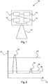
- FIG. 1 shows a block diagram of a radar level gauge 10 according to an embodiment of the invention.
- the radar level gauge can be configured in particular for determining a level of a medium, for example in a container, based on a transit time principle.
- the radar level gauge 10 has a control unit 11, a memory unit 14 and / or a memory device 14, a transmitting unit 12, a receiving unit 13 and an antenna 15.
- the transmitting unit 12 and the receiving unit 13 can also be combined to form a transceiver unit 12, 13.
- a transmission signal can be emitted in the direction of the medium, wherein a part of the transmission signal is reflected on the surface of the medium and can be received as a received signal via the antenna 15.
- the received signal can optionally be filtered by means of at least one filter and / or amplified by means of at least one amplifier.
- the optionally filtered and / or amplified received signal can then be sampled by means of an A / D converter and evaluated as a digital measurement signal which correlates with the received signal.
- control unit 11 is configured to communicate with the transmitting unit 12 and / or the receiving unit 13.
- control unit 11 can vary, change and / or adapt a transmission power and / or a transmission level of the transmission signal.
- control unit 11 may be configured to query a current transmission power from the transmitting unit 12.
- the transmission power and / or the transmission level can be described and / or specified via an absolute, relative or percentage value.
- the control unit 11 can thus receive the information that, for example, the transmission signal is currently transmitted with 80% of the maximum possible transmission power.
- control unit 11 is configured to determine the transmission power. Furthermore, the control unit 11 is set up to determine, adapt, calculate, vary and / or change a value of at least one evaluation parameter based on the determined transmission power.
- the value of the at least one evaluation parameter may be a threshold value at which, if it is exceeded and / or undershot, a part of the measurement signal, for example a peak, is detected and / or evaluated by the control unit 11 as a reflection from the surface of the medium. Based on the varied value of the at least one evaluation parameter, the fill level of the medium can thus be reliably determined taking into account the transmission power.
- the value of the at least one evaluation parameter may be stored in the memory device 14, for example.
- control unit 11 may be configured to determine the fill level based on the received signal and / or the measurement signal and based on a plurality of evaluation parameters.
- a parameter set of evaluation parameters can be stored in the memory unit 14, which and / or their values can represent a false signal suppression, as in FIG FIGS. 3 and 4 described in detail.
- the Störsignalausblendung may include about an impurity profile and / or a container empty profile.
- the control unit 11 is set up to vary, change, calculate and / or adjust values of the false signal blanking and / or values of the parameter set of the false signal blanking based on the determined transmit power.
- a precision of the level detection can be increased with adaptive transmission level in an advantageous manner.
- the Störsignalausblendung and / or values of Störsignalausblendung can be determined in the context of at least one reference measurement with the radar level gauge 10 at a known level, preferably with an empty container, with known transmission power. Another false signal suppression and / or values of another Noise suppression can be determined in the context of a further reference measurement at a further transmission power, which may differ from the transmission power of the previous reference measurement. Based on an interpolation and / or extrapolation then values of Störsignalausblendung can be adapted to the current transmission power. The same method can also be used for an evaluation parameter which is present as a threshold value and / or for any other evaluation parameter.
- FIG. 2 1 illustrates a measurement signal 30 determined using a radar fill level measuring device 10 according to the invention.
- the measurement signal 30 may be a digital representation of the received signal, a so-called echo curve 30, as in the control unit 11 and / or in the memory device 14 of the radar level gauge 10 the A / D conversion can be present.
- the x-axis 22 in this case represents a time axis 22, ie a signal propagation time of the transmit and / or receive signal, and the y-axis 21 represents a signal strength 21 and / or amplitude 21 of the measurement signal 30.
- the time axis 21 correlates with a distance the level measuring device 10.
- the measurement signal 30 has a first reflection 31, which may be caused for example by reflection of a portion of the transmission signal to the antenna 15 of the radar level gauge 10, and a second reflection 32, which by a reflection 32 of the transmission signal at the Surface of the medium may be caused.
- a threshold value 23 is shown, which is a value of an evaluation parameter.
- the control unit 11 is configured to recognize and / or evaluate the second reflection 32, which occurs after the first reflection 31 of the antenna 15 as reflection 32 on the product surface, when the amplitude 21 of the second reflection 32 exceeds the threshold value 23 .
- the defined threshold 23 may correspond approximately to a threshold at maximum transmission power of the radar level gauge 10.
- the transmission signal in the in FIG. 2 example shown has been sent with reduced transmission power, so that the resulting reflection 32 of the measurement signal 30 on the product surface does not reach and / or exceed the threshold value 23. Thus, the reflection 32 of the level would not be recognized as a level.
- the control unit 11 is therefore set up to determine a current transmission power and to adjust, change and / or vary the threshold value 23 based on the determined transmission power. Based on the determined transmission power, the control unit 11 can reduce the threshold value 23 to a lower threshold value 24, so that the reflection 32 exceeds the adapted threshold value 24 and can be determined as a reflection 32 on the product surface.
- the threshold value 24 can be calculated by the control unit 11 based on the current transmission power, a formula, a model and / or a characteristic field and / or stored in the memory device 14.
- the measurement signal 30 and / or the received signal can be increased by the control unit 11 based on the current transmission power, so that the reflection 32 reaches and / or exceeds the threshold value 23 and is thus detected as reflection 32 of the product surface.
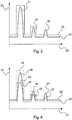
- FIG. 3 illustrates a determined with a radar level measurement device 10 according to the invention measuring signal 30 with a Störsignalausblendung 25.
- the measurement signal 30 may be a digital representation of the received signal, ie an echo curve 30, as may be present in the control unit 11 and / or in the storage device 14 of the radar level gauge 10 after the A / D conversion.
- the x-axis 22 in this case represents a time axis 22, ie a signal propagation time of the transmit and / or receive signal, and the y-axis 21 represents a signal strength 21 and / or amplitude 21 of the measurement signal 30.
- the time axis 21 correlates with a distance the Level gauge 10, so that based on the measurement signal 30, the level can be determined.
- the Störsignalausblendung 25 may include about an impurity profile and / or a container empty profile.
- the Störsignalausblendung 25 for this purpose have a parameter set of evaluation parameters, which can be stored in the memory unit 14.
- the evaluation parameters of the interference signal blanking may each correspond to a respective time interval, and the values of the respective evaluation parameters may correspond to an amplitude and / or a signal strength of the measurement signal 30 in this time interval.
- the Störsignalausblendung 25 can thus form a curve 25, with which the measurement signal 30 can be compared to determine the level.
- FIG. 3 is a reflection 31 of the antenna 15 and a Störreflexion 33 shown, which may be caused by container installations.
- a reflection 32 shown on the product surface which can be identified by the Störsignalausblendung 25.
- the control unit 11 may be configured to discard the reflections 31 and 33 if they do not exceed the values of the interference suppression 25.
- the control unit 11 can be configured to identify the reflection 32 as reflection 32 originating from the product surface, when the reflection 32 exceeds the values of the false signal suppression 25. In this way, the level can be reliably determined.
- the Störsignalausblendung 25 can be calculated approximately from the received measurement signal of a reference measurement, for example by means of a filter.
- a defined level preferably an empty container, the container and its reflections are measured.
- the transmission power of the radar level gauge 10 is known.
- FIG. 4 illustrates a variation, change and / or adaptation of the Störsignalausblendung 25 FIG. 3 by the control unit 11 of the radar level gauge depending on the transmission power of the transmission signal.
- Analogous to FIG. 3 show the individual peaks 31, 32, 33 in the measurement signal 30, which was determined based on a transmission signal with a first transmission power and / or a reception signal with a first reception power, a reflection 31 of the antenna 15, a reflection 33 on a faulty object and a reflection 32 on the product surface.
- FIG. 4 shows FIG. 4 a second measurement signal 30 ', which was determined based on a transmission signal with a second transmission power and / or a reception signal with a second reception power.
- the second transmission power is greater than the first transmission power, so that the amplitudes of the reflections 36, 37, 38 of the second measurement signal 30 'are each greater than the amplitudes of the reflections 31, 32, 33 of the first measurement signal 30.
- the reflections 36 and 38 of the second measurement signal 30 ' ie at the higher transmission power, exceed values of the interference signal suppression 25.
- the control unit 11 could thus identify the reflections 36, 38 as originating from the product surface.
- the control unit 11 is set up to determine the current transmit power, based for example on a query of the transmit power from the transmit unit 12.
- the control unit 11 can also specify the transmit power itself.
- the control unit 11 is furthermore set up to adjust and / or change values of the evaluation parameters, ie values of the false signal suppression 25, based on the determined transmission power.
- the control unit determines values of a further and / or current false signal suppression 26 in order to take into account and / or to take into account the increased transmission power.
- the control unit 11 or the evaluation electronics can adapt the interference signal suppression 25 to the varied transmission power of the radar level gauge 10, which leads to a calculated, current interference suppression 26.
- the received signal received by the reception unit and / or the measurement signal 30 correlating therewith can also be varied and / or adapted in accordance with the current transmission power.
- the measurement signal 30 ' may be scaled and / or shifted at the higher transmit power to provide the measurement signal 30, which may then be compared to the values of the noise blanking 25.
- the first interference suppression 25 can be determined, for example, when the container is empty and the transmission power is at a minimum.
- the calculated interference suppression 26 can be determined, for example, based on a known behavior, relationship and / or a formula between minimum and maximum transmission power. For example, there may be a certain amplitude difference in the measurement signal, such as a difference of 3dB, between minimum and maximum transmission power. If such parameters and / or such a behavior of the transmitting and receiving unit 12, 13 are known, for example by measurements and / or modeling of the circuit, an adapted Störsignalausblendung 26 can be calculated.
- values of the evaluation parameters for example based on a mathematical formula, a model and / or a characteristic field which can represent and / or indicate the relationship between the values of the evaluation parameters and the transmission power, can be determined with the current transmission power as the input variable for the current transmission power, as in FIG. 5 illustrated.
- the Störsignalausblendung 26 can be determined by a second reference measurement at a second transmission power.
- the first transmission power can correspond to a minimum transmission power
- the second transmission power can correspond to a maximum transmission power.
- the control unit 11 may then based on an interpolation and / or scaling between the values of the first interference suppression 25 and the values of the second interference suppression 26 determine values of interference suppression for a current transmission power.
- the interpolation may, for example, be linear, quadratic, logarithmic or exponential, in each case proportional or indirectly proportional to the transmission power.
- the control unit 11 may change the Störsignalausblendung by a shift and / or scaling.
- the determination of the Störsignalausblendung 25 can be done when commissioning the radar level gauge 10. This can be carried out automatically by the control unit 11 of the radar level gauge 10 and / or by a user input, such as by pressing a button and / or pressing an operating element of the level gauge 10, initiated. Further, the control unit 11 may be configured to periodically repeat the reference measurement of the false signal suppression, e.g. always when the container is empty or has a low level. In other words, a reaching and / or falling below a certain level, in particular a minimum level, trigger the reference measurement for the Störsignalausblendung and / or trigger.
- the interference suppression 25 or the interference signal suppression determined in this way can be stored or stored in a memory unit 14 of the radar level gauge 10.
- the Störsignalausblendung By determining the Störsignalausblendung at minimum and maximum transmission power can be responded to each transmit power accordingly, or the Störsignalausblendung can be varied accordingly, adapted or changed. If e.g. sent with only 50% of the maximum transmission power, so the noise false to be taken 26 can be calculated from the average of the first Störsmausausblendung 25 and the second Störsmausausblendung 26.
- the control unit 11 can take into account, for example by a map or a function, the values of the interference suppression at a first transmission power and / or a second transmission power into values of the Störsignalausblendung converted at the current transmission power.
- the current interference signal suppression can be generated from the at least one reference measurement and / or with the aid of a mathematical model or a formula.
- the function can also be a non-linear function.
- various functions depending on the environmental conditions, such as pressure, temperature, humidity and / or gas composition be deposited.
- the control unit 11 may also take into account other influencing variables such as pressure, temperature, humidity and / or gas composition in the container.
- FIG. 5 illustrates a variation of values of evaluation parameters by a radar level gauge 10 according to one embodiment of the invention.
- the values p 0 , p 1 , p 2 ,..., P n of the individual evaluation parameters can all be varied with the same function f or at least parts of the evaluation parameters with different functions, so that the variation and / or the relative difference between, for example p 0 to p ' 0 and p 1 to p' 1 does not necessarily have to be identical.
- the function may also depend on other variables, such as temperature, humidity, pressure and / or gas composition in the container.
- FIG. 6 is a flowchart illustrating steps of a method of operating a radar level gauge 10 according to one embodiment of the invention.
- the radar level gauge 10 may be a radar level gauge 10 as described in the preceding figures.
- a transmission signal in particular a radar transmission signal, is transmitted in the direction of the medium with the previously determined transmission power by the transmission unit 12.
- the emitted signal is reflected on the surface of the medium and received by the receiving unit 13 of the radar level gauge 10 in step S3.
- step S4 calculating, determining, changing, varying and / or adapting at least one value of an evaluation parameter and / or a measurement signal correlating with the received signal is performed based on the determined transmission power of the transmitting unit 12. Determining the fill level of the medium based on the received signal and / or based on the varied value of the at least one evaluation parameter takes place in step S5. This simplifies the evaluation of a measuring signal of a radar level gauge and improves the quality of the measurement.
- the radar level gauge can be put into operation in one step and it can be a measurement signal of the reference measurement, ie a Störsignalausblendung stored. Subsequently, a measuring cycle can be run through and the current transmission level can be determined. The transmission signal can be sent and the reception signal can be received. Values of the interference signal suppression and / or at least one threshold value can be calculated on the basis of the determined transmission power. The received signal can be converted into a digital measurement signal and with calculated values of the Noise suppression and / or compared with the at least one threshold. Subsequently, the fill level can be determined from the received measurement signal, the adjusted interference signal suppression and / or the threshold value.
- Level gauges may e.g. record the amplitudes of the reflections in the container.
- the amplitude of the reflection of the medium surface provides information about whether the level measuring device 10 detects the current measurement situation sufficiently accurately or whether the process conditions have deteriorated.
- the amplitude is e.g. Plotted over the location so as to obtain an amplitude profile of the reflection of the level in the whole tank with which then the amplitude of the reflection of the level of the current measurement can be compared.
- the transmission level should remain the same or, according to the invention, the amplitude of the reflection or the amplitude profile itself should be recalculated.
Abstract
Es wird ein Radar-Füllstandmessgerät (10) zum Ermitteln eines Füllstandes eines Mediums vorgeschlagen. Das Radar-Füllstandmessgerät (10) weist eine Sendeeinheit (12) zum Senden eines Sendesignals, eine Empfangseinheit (13) zum Empfangen eines an dem Medium reflektierten Empfangssignals und eine Steuereinheit (11) auf. Die Steuereinheit (11) ist dazu eingerichtet, basierend auf dem Empfangssignal und basierend auf wenigstens einem Auswerteparameter den Füllstand des Mediums zu ermitteln. Das Radar-Füllstandmessgerät (10) ist ferner dazu eingerichtet, eine Sendeleistung des Sendesignals zu variieren. Die Steuereinheit (11) ist ferner dazu eingerichtet, eine aktuelle Sendeleistung des Sendesignals zu ermitteln. Die Steuereinheit (11) ist dazu eingerichtet, zur Ermittlung des Füllstandes einen Wert des wenigstens einen Auswerteparameters, das Empfangssignal und/oder wenigstens ein mit dem Empfangssignals korrelierendes Messsignal (30) basierend auf der ermittelten, aktuellen Sendeleistung zu variieren, sodass der Füllstand unter Berücksichtigung der Sendeleistung ermittelt ist.

Description
Die Erfindung betrifft allgemein das Gebiet der radarbasierten Füllstandmessung. Insbesondere betrifft die Erfindung ein Radar-Füllstandmessgerät mit adaptiver Sendeleistung zur Bestimmung eines Füllstandes eines Mediums. Ferner betrifft die Erfindung ein Verfahren zum Betreiben eines solchen Radar-Füllstandmessgerätes. Des Weiteren betrifft die Erfindung ein Programmelement, welches ein Radar-Füllstandmessgerät anleitet, das Verfahren durchzuführen, und ein computerlesbares Speichermedium, auf welchem das Programmelement gespeichert ist.The invention generally relates to the field of radar-based level measurement. In particular, the invention relates to a radar level gauge with adaptive transmission power for determining a level of a medium. Furthermore, the invention relates to a method for operating such a radar level gauge. Furthermore, the invention relates to a program element which instructs a radar level gauge to perform the method, and a computer-readable storage medium on which the program element is stored.
Radarbasierte Füllstandmessgeräte und/oder Radar-Füllstandmessgeräte weisen in der Regel ein Radarmodul zur Erzeugung eines Sendesignals, insbesondere eines hochfrequenten Radarsendesignals, auf.Radar-based level measuring devices and / or radar level measuring devices generally have a radar module for generating a transmission signal, in particular a high-frequency radar transmission signal.
Allgemein wird bei Radar-Füllstandmessgeräten das Sendesignal bzw. das Radarsendesignal an eine Oberfläche eines Mediums abgestrahlt, wobei ein Teil des Sendesignals an der Oberfläche reflektiert wird und wiederum von dem Radar-Füllstandmessgerät als Empfangssignal empfangen wird. Basierend auf einem Laufzeitverfahren kann so die Entfernung des Radar-Füllstandmessgeräts zur Oberfläche des Mediums und/oder der Füllstand des Mediums ermittelt werden.Generally, in radar level gauges, the transmit signal or the radar transmit signal is radiated to a surface of a medium, wherein a portion of the transmit signal is reflected at the surface and in turn is received by the radar level gauge as a receive signal. Based on a runtime method so can the Distance of the radar level gauge to the surface of the medium and / or the level of the medium can be determined.
Das Empfangssignal wird zur eigentlichen Bestimmung des Füllstandes in der Regel in ein digitales Messsignal gewandelt, welches mit dem Empfangssignal korreliert. Das erhaltene Messsignal wird anschließend häufig unter Berücksichtigung wenigstens eines Auswerteparameters ausgewertet und/oder verarbeitet. Beispielsweise kann eine vordefinierte und feste Schwelle für eine Amplitude des Empfangssignals zur Auswertung herangezogen werden. Beispielsweise können Signalanteile des Messsignals und/oder Messwerte, welche die Schwelle nicht erreichen und/oder überschreiten bei der Ermittlung des Füllstandes unberücksichtigt bleiben.The received signal is converted to the actual determination of the level usually in a digital measurement signal, which correlates with the received signal. The measurement signal obtained is then frequently evaluated and / or processed taking into account at least one evaluation parameter. For example, a predefined and fixed threshold for an amplitude of the received signal can be used for the evaluation. For example, signal components of the measurement signal and / or measured values which do not reach the threshold and / or exceed can be disregarded in the determination of the fill level.
Es ist eine Aufgabe der Erfindung, ein verbessertes und flexibel einsetzbares Radar-Füllstandmessgerät bereitzustellen.It is an object of the invention to provide an improved and flexibly usable radar level gauge.
Diese Aufgabe wird durch den Gegenstand der unabhängigen Ansprüche gelöst. Ausführungsformen und Weiterbildungen der Erfindung sind den abhängigen Ansprüchen, der Beschreibung und den Figuren zu entnehmen.This object is solved by the subject matter of the independent claims. Embodiments and developments of the invention are described in the dependent claims, the description and the figures.
Ein erster Aspekt der Erfindung betrifft ein Radar-Füllstandmessgerät, im Folgenden auch Füllstandmessgerät genannt, zum Ermitteln eines Füllstandes eines Mediums. Das Radar-Füllstandmessgerät weist eine Sendeeinheit zum Senden eines Sendesignals, eines Radarsendesignals und/oder eines Radarsignals in Richtung des Mediums auf. Weiter weist das Radar-Füllstandmessgerät eine Empfangseinheit zum Empfangen eines an dem Medium und/oder an einer Oberfläche des Mediums reflektierten Empfangssignals und/oder Radarempfangssignals sowie eine Steuereinheit auf. Die Steuereinheit ist dazu eingerichtet, basierend auf dem Empfangssignal und basierend auf wenigstens einem Auswerteparameter den Füllstand des Mediums zu ermitteln. Das Radar-Füllstandmessgerät ist ferner dazu eingerichtet, eine Sendeleistung und/oder einen Sendepegel des Sendesignals zu variieren, zu verändern und/oder anzupassen. Das Radar-Füllstandmessgerät kann somit ein Füllstandmessgerät mit adaptiver Sendeleistung sein. Die Steuereinheit ist ferner dazu eingerichtet, eine aktuelle Sendeleistung des Sendesignals zu ermitteln und/oder eine Variation der Sendeleistung relativ zu einer vorhergehenden und/oder vergangenen Füllstandmessung zu ermitteln. Des Weiteren ist die Steuereinheit dazu eingerichtet, zur Ermittlung des Füllstandes einen Wert des wenigstens einen Auswerteparameters, das Empfangssignal und/oder wenigstens ein mit dem Empfangssignal korrelierendes Messsignal basierend auf der ermittelten, aktuellen Sendeleistung zu ermitteln, zu berechnen, zu variieren, zu verändern und/oder anzupassen, sodass der Füllstand unter Berücksichtigung der aktuellen Sendeleistung ermittelt ist.A first aspect of the invention relates to a radar fill level measuring device, also referred to below as level gauge, for determining a fill level of a medium. The radar level gauge has a transmitting unit for transmitting a transmission signal, a radar transmission signal and / or a radar signal in the direction of the medium. Furthermore, the radar fill level measuring device has a receiving unit for receiving a received signal and / or radar receiving signal reflected on the medium and / or on a surface of the medium and also a control unit. The control unit is set up to based on the received signal and based on at least one evaluation parameter to determine the level of the medium. The radar level gauge is further configured to vary, alter and / or adapt a transmission power and / or a transmission level of the transmission signal. The radar level gauge can thus be a level gauge with adaptive transmission power. The control unit is further configured to determine a current transmission power of the transmission signal and / or to determine a variation of the transmission power relative to a previous and / or past level measurement. Furthermore, the control unit is configured to determine, calculate, vary, and change a value of the at least one evaluation parameter, the received signal and / or at least one measurement signal correlating with the received signal based on the determined, current transmission power / or adjust so that the level is determined taking into account the current transmission power.
Das erfindungsgemäße Radar-Füllstandmessgerät kann insbesondere zur Ermittlung des Füllstandes nach dem Laufzeitprinzip ausgestaltet sein. Die Erfindung kann jedoch auch in anderen Füllstandmessgeräten in vorteilhafter Weise eingesetzt werden, beispielsweise in Ultraschall-Füllstandmessgeräten, in optischen Füllstandmessgeräten und/oder radiometrischen Füllstandmessgeräten.The radar level measuring device according to the invention can be designed in particular for determining the level according to the transit time principle. However, the invention can also be used in other level measuring devices in an advantageous manner, for example in ultrasonic level gauges, in optical level gauges and / or radiometric level gauges.
Der Auswerteparameter kann hier und im Folgenden einen Parameter bezeichnen, welcher zur Auswertung des Empfangssignals und/oder zur Auswertung des mit dem Empfangssignal korrelierenden Messsignals von der Steuereinheit berücksichtigt und/oder herangezogen wird. Beispielsweise kann die Steuereinheit dazu eingerichtet sein, zumindest einen Teil des Empfangssignals und/oder des Messsignals mit einem Wert des Auswerteparameters zu vergleichen, um den Füllstand des Mediums zu ermitteln und/oder zu bestimmen.The evaluation parameter may here and below denote a parameter which is taken into consideration and / or used by the control unit for evaluating the received signal and / or for evaluating the measurement signal correlating with the received signal. For example, the control unit may be configured to compare at least a portion of the received signal and / or the measured signal with a value of the evaluation parameter in order to determine and / or determine the fill level of the medium.
Die Sendeeinheit kann etwa eine Sendeschaltung, einen Sendekanal und/oder einen Sendeschaltkreis des Radar-Füllstandmessgeräts bezeichnen. Analog kann die Empfangseinheit eine Empfangsschaltung, einen Empfangskanal und/oder einen Empfangsschaltkreis des Radar-Füllstandmessgeräts bezeichnen. Die Sendeeinheit und die Empfangseinheit können dabei auch als kombinierte Sende-Empfangseinheit ausgebildet sein. Die Sende-Empfangseinheit kann beispielsweise eine Sende-Empfangsweiche zur Differenzierung, insbesondere zur zeitlichen Differenzierung, des Sendesignals und des zum Sendesignal zeitlich verzögerten Empfangssignals aufweisen. Ferner kann die Steuereinheit eine Logikeinheit, eine Steuerschaltung, einen Steuerschaltkreis, eine Auswerteschaltung und/oder ein Steuerwerk bezeichnen.The transmitting unit may, for example, designate a transmitting circuit, a transmitting channel and / or a transmitting circuit of the radar level gauge. Analogously, the receiving unit may denote a receiving circuit, a receiving channel and / or a receiving circuit of the radar level gauge. The transmitting unit and the receiving unit can also be designed as a combined transceiver unit. The transceiver unit can, for example, have a transceiver for differentiation, in particular for time differentiation, of the transmission signal and of the reception signal delayed in time with respect to the transmission signal. Furthermore, the control unit may designate a logic unit, a control circuit, a control circuit, an evaluation circuit and / or a control unit.
Bei Radar-Füllstandmessgeräten wird das Sendesignal von der Sendeeinheit in Richtung des Mediums abgestrahlt und an der Oberfläche des Mediums zumindest teilweise reflektiert. Das an der Oberfläche des Mediums reflektierte Empfangssignal kann durch die Empfangseinheit des Füllstandmessgeräts empfangen werden. Die Signallaufzeit zwischen dem Sendesignal und dem Empfangssignal kann durch das Füllstandmessgerät und/oder die Steuereinheit des Radar-Füllstandmessgeräts bestimmt werden. Hieraus kann bei bekannter Ausbreitungsgeschwindigkeit des Sendesignals und/oder des Empfangssignal und beispielsweise unter Berücksichtigung einer Einbaulage des Füllstandmessgeräts der Füllstand des Mediums bestimmt werden.In radar level measurement devices, the transmission signal is emitted by the transmitting unit in the direction of the medium and at least partially reflected on the surface of the medium. The received signal reflected on the surface of the medium can be received by the receiving unit of the level meter. The signal transit time between the transmission signal and the reception signal can be determined by the level measurement device and / or the control unit of the radar level gauge. It can be determined at a known propagation speed of the transmission signal and / or the received signal and, for example, taking into account a mounting position of the level measuring device, the level of the medium.
Die Erfindung kann insbesonders als auf den nachfolgend beschriebenen Erkenntnissen beruhend angesehen werden. Bei Radar-Füllstandmessgeräten kann es vorteilhaft sein, die Sendeleistung und/oder einen Sendepegel des Sendesignals zu variieren, anzupassen und/oder zu verändern, um so beispielsweise einer aktuellen Messaufgabe gerecht zu werden. So kann etwa bei einem gut reflektierenden Medium und/oder Messgut, welches das ausgesendete Sendesignal größtenteils reflektiert, die Sendeleistung und/oder der Sendepegel reduziert werden. Hingegen kann es bei einem Medium, welches nur einen geringen Anteil des Sendesignals reflektiert, vorteilhaft sein, die Sendeleistung und/oder den Sendepegel zu erhöhen, um so ein auswertbares und aussagekräftiges Empfangssignal zu erhalten. Es sei angemerkt, dass ein schwach reflektiertes Sendesignal, d.h. ein Empfangssignal mir geringer Empfangsleistung und/oder geringem Empfangspegel, nicht zwingend auf die physikalischen Eigenschaften des zu messenden Mediums zurückgeführt werden kann. Bei einem Radar-Füllstandmessgerät kann beispielsweise eine Anhaftung an und/oder eine Verschmutzung der Antenne die Empfangseigenschaften beinträchtigen, so dass eine Erhöhung der Sendeleistung vorteilhaft sein kann, um weiterhin den Füllstand bzw. die Füllhöhe präzise erfassen zu können. Des Weiteren kann durch die Variation der Sendeleistung der Sendeeinheit eine manuelle Wartung des Radar-Füllstandmessgeräts hinausgezögert werden oder sogar überflüssig werden. Ferner kann durch die Anpassung der Sendeleistung der nötige Energieaufwand des Radar-Füllstandmessgeräts für eine Messung reduziert werden.In particular, the invention may be considered to be based on the findings described below. In the case of radar fill level measuring devices, it may be advantageous to vary, adapt and / or change the transmission power and / or a transmission level of the transmission signal in order to do justice, for example, to a current measuring task. Thus, for example, in the case of a well-reflecting medium and / or material to be measured, which largely reflects the transmitted transmission signal, the transmission power and / or the transmission level can be reduced. On the other hand, with a medium containing only a small proportion of the Transmitted signal reflects, be advantageous to increase the transmission power and / or the transmission level, so as to obtain an evaluable and meaningful reception signal. It should be noted that a weakly reflected transmission signal, ie a reception signal with low reception power and / or low reception level, can not necessarily be attributed to the physical properties of the medium to be measured. In the case of a radar level-measuring device, for example, adhesion to and / or contamination of the antenna may impair the reception properties, so that an increase in the transmission power may be advantageous in order to be able to more accurately detect the fill level or fill level. Furthermore, by the variation of the transmission power of the transmitting unit manual maintenance of the radar level gauge can be delayed or even superfluous. Furthermore, by adjusting the transmission power of the necessary energy consumption of the radar level gauge can be reduced for a measurement.
Der von dem Medium reflektierte und zumindest teilweise als Empfangssignal empfangene Teil des Sendesignals kann etwa mit schaltungstechnischem Aufwand, z.B. in Form wenigstens eines Filters und/oder Verstärkers, gefiltert und/oder verstärkt werden. Anschließend erfolgt im Regelfall eine Analog-Digital-Wandlung (A/D-Wandlung) des Empfangssignals. Dabei kann das Empfangssignal abgetastet werden und digitalisierte Abtastwerte des Empfangssignals, welche hier und im Folgenden als mit dem Empfangssignal korrelierendes Messsignal bezeichnet sein können, können in einem Datenspeicher, einer Speichereinrichtung und/oder einer Speichervorrichtung des Radar-Füllstandmessgeräts hinterlegt und mittels der Steuereinheit, etwa mittels eines Mikrocontrollers oder einer anderweitigen Steuereinheit, zur Ermittlung eines Abstandes zwischen Medium und Radar-Füllstandmessgerät und/oder zur Ermittlung eines Füllstandes des Mediums ausgewertet werden. Die Steuereinheit kann dazu eingerichtet sein, beispielsweise mittels eines geeigneten Auswerteverfahrens und/oder Auswertealgorithmus, aus dem abgetasteten Empfangssignal, d.h. dem mit dem Empfangssignal korrelierenden, digitalen Messsignal, die Reflexion an der Oberfläche des Mediums zu bestimmen und basierend darauf den Füllstand des Mediums zu bestimmen. Andere Reflexionen in dem Empfangssignal und/oder dem Messsignal, die z.B. durch Behältereinbauten, wie Rührwerke, Sichtfenster und/oder Anschlüsse, durch die Antenne des Radar-Füllstandmessgeräts selbst und/oder durch Verschmutzungen entstehen können, sollten von der Steuereinheit erkannt werden und als Reflexion an der Oberfläche des Mediums und/oder des Füllguts ausgeschlossen werden. Bei gängigen Radar-Füllstandmessgeräten kann hierfür ein oder mehrere Auswerteparameter herangezogen werden, wobei der wenigstens eine Auswerteparameter etwa eine vordefinierte und feste Schwelle, ein Schwellwert und/oder eine fester Grenzwert für die Amplitude des Empfangssignals und/oder des digitalen Messsignals sein kann. Ein Wert des wenigstens einen Auswerteparameters kann so etwa einen Schwellwert für die Amplitude des Empfangssignals und/oder des Messsignals bezeichnen. So können beispielsweise eine erste Schwelle, unterhalb derer Anteile des Messsignals verworfen werden, und eine zweite Schwelle, oberhalb derer Anteile des Messsignals verworfen werden, definiert sein. Auch können der Einbau des Radar-Füllstandmessgeräts und/oder die physikalischen Eigenschaften des zu messenden Mediums im Radar-Füllstandmessgerät mittels weiterer vordefinierter und fester Auswerteparameter parametriert werden und/oder in einer Speichervorrichtung in dem Radar-Füllstandmessgerät hinterlegt und/oder gespeichert sein. Die Steuereinheit kann basierend auf der Gesamtheit von voranstehend erläuterten Auswerteparametern und/oder den zugehörigen Werten dieser Auswerteparameter ermitteln, ob es sich bei einem Anteil des Messsignals, etwa einem Peak in dem Messsignal, um eine unerwünschte Störung, wie eine Reflexion an der Antenne des Radar-Füllstandmessgeräts und/oder an Behältereinbauten, oder um die zu messende Oberfläche des Mediums handelt. Eine Hinterlegung von festen Werten der Auswerteparameter in einer Speichervorrichtung des Füllstandmessgeräts kann jedoch bei Variation der Sendeleistung zu einer Verfälschung der Messergebnisse führen, da etwa bei zu geringer Sendeleistung und damit einhergehend zu geringer Empfangsleistung des Empfangssignals eine Amplitude des Empfangssignals und/oder des damit korrelierenden Messsignals zumindest in einem Teilbereich zu gering sein kann. Eine von der Oberfläche des Mediums stammende Reflexion kann so etwa von der Steuereinheit fälschlicherweise als eine Störreflexion erkannt und/oder verworfen werden.The portion of the transmission signal which is reflected by the medium and at least partially received as a received signal can be filtered and / or amplified, for example with circuit complexity, for example in the form of at least one filter and / or amplifier. Subsequently, as a rule, an analog-to-digital conversion (A / D conversion) of the received signal. In this case, the received signal can be sampled and digitized sampled values of the received signal, which here and below may be referred to as the measuring signal correlating with the received signal, can be stored in a data memory, a memory device and / or a memory device of the radar fill level measuring device and by means of the control unit, for example be evaluated by means of a microcontroller or other control unit, to determine a distance between the medium and radar level gauge and / or to determine a level of the medium. The control unit may be configured, for example by means of a suitable evaluation method and / or evaluation algorithm, to determine the reflection on the surface of the medium from the sampled received signal, ie the digital measuring signal correlated with the received signal, and based thereon to the fill level of the medium determine. Other reflections in the received signal and / or the measurement signal, which may arise, for example, through vessel installations, such as agitators, viewing windows and / or connections, through the antenna of the radar level gauge itself and / or due to contamination, should be recognized by the control unit and as a reflection be excluded on the surface of the medium and / or the contents. One or more evaluation parameters can be used for common radar level measurement devices, wherein the at least one evaluation parameter can be approximately a predefined and fixed threshold, a threshold value and / or a fixed limit value for the amplitude of the received signal and / or the digital measurement signal. A value of the at least one evaluation parameter may thus for example denote a threshold value for the amplitude of the received signal and / or the measuring signal. Thus, for example, a first threshold, below which portions of the measurement signal are discarded, and a second threshold, above which portions of the measurement signal are discarded, be defined. The installation of the radar level gauge and / or the physical properties of the medium to be measured in the radar level gauge can be parameterized by means of further predefined and fixed evaluation parameters and / or deposited and / or stored in a memory device in the radar level gauge. Based on the totality of evaluation parameters explained above and / or the associated values of these evaluation parameters, the control unit can determine whether a portion of the measurement signal, for example a peak in the measurement signal, is an undesired disturbance, such as a reflection at the antenna of the radar Level gauge and / or vessel installations, or is the surface of the medium to be measured. A deposit of fixed values of the evaluation parameters in a memory device of the level gauge, however, can lead to a falsification of the measurement results with varying transmission power, since, for example, if the transmission power is too low and, as a consequence, the received signal receiving power is too low, an amplitude of the received signal and / or the measuring signal correlated therewith can be too low, at least in one subarea. One from the surface of the Media originating reflection may be erroneously recognized by the control unit as a spurious reflection and / or discarded.
Um auch bei einem adaptiven Sendepegel und/oder einer adaptiven Sendeleistung sicherzustellen, dass das empfangene Empfangssignal und das damit korrelierende digitale Messsignal zuverlässig und präzise ausgewertet werden kann, ist die Steuereinheit erfindungsgemäß dazu eingerichtet, die Sendeleistung zu ermitteln und einen Wert des wenigstens einen Auswerteparameters entsprechend der Sendeleistung und/oder basierend auf der Sendeleistung zu ermitteln, zu verändern, zu skalieren, zu variieren und/oder anzupassen. So kann bei Erhöhung der Sendeleistung, etwa relativ zu einer vorhergehenden Messung, der Wert des Auswerteparameters entsprechend erhöht werden, und bei einer Verringerung der Sendeleistung kann der Wert entsprechend reduziert werden. Auch kann die Steuereinheit dazu eingerichtet sein, eine Variation der Sendeleistung relativ zu einer vorhergehenden Messung zu ermitteln, und den Wert des wenigstens einen Auswerteparameters entsprechend der ermittelten Variation zu variieren, anzupassen und/oder zu verändern. Die ermittelte Variation kann dabei einen Betrag, um welchen die Sendeleistung variiert wurde, und eine Richtung bzw. ein Vorzeichen der Variation umfassen. Mit anderen Worten kann die Steuereinheit dazu eingerichtet sein, den Betrag der Variation zu ermitteln, und zu ermitteln, ob die Sendeleistung relativ zur vorhergehenden Messung erhöht oder reduziert wurde. Hierdurch kann die Qualität der Auswertung des Empfangssignals und/oder des damit korrelierenden digitalen Messsignals erhöht werden. Insgesamt kann so eine Präzision und/oder Genauigkeit der Füllstandmessung verbessert werden und es kann ein verbessertes Füllstandmessgerät bereitgestellt werden.In order to ensure that the received received signal and the digital measurement signal correlating therewith can be evaluated reliably and precisely even with an adaptive transmission level and / or an adaptive transmission power, the control unit according to the invention is configured to determine the transmission power and corresponding to a value of the at least one evaluation parameter the transmission power and / or based on the transmission power to determine, change, scale, vary and / or adapt. Thus, when the transmission power is increased, for example, relative to a previous measurement, the value of the evaluation parameter can be increased accordingly, and if the transmission power is reduced, the value can be reduced accordingly. The control unit can also be set up to determine a variation of the transmission power relative to a preceding measurement, and to vary, adapt and / or change the value of the at least one evaluation parameter in accordance with the determined variation. The determined variation may comprise an amount by which the transmission power has been varied and a direction or a sign of the variation. In other words, the control unit may be configured to determine the amount of variation and to determine whether the transmit power has been increased or decreased relative to the previous measurement. As a result, the quality of the evaluation of the received signal and / or the digital measuring signal correlated therewith can be increased. Overall, such a precision and / or accuracy of the level measurement can be improved and it can be provided an improved level gauge.
Alternativ oder zusätzlich kann die Steuereinheit dazu eingerichtet sein, das Empfangssignal und/oder das damit korrelierende Messsignal basierend auf und/oder entsprechend der Sendeleistung zu variieren, zu skalieren, zu verändern und/oder anzupassen. Beispielsweise kann das Empfangssignal und/oder das Messsignal entsprechend der Sendeleistung verstärkt oder reduziert werden.Alternatively or additionally, the control unit may be configured to vary, scale, change and / or adapt the received signal and / or the measurement signal correlating therewith based on and / or in accordance with the transmission power. For example the received signal and / or the measuring signal can be amplified or reduced in accordance with the transmission power.
Die Variation, Einstellung und/oder Adaption der Sendeleistung selbst kann beispielsweise anhand des empfangenen Empfangssignal einer zeitlich vorhergehenden Messung oder zeitlich vorhergehender Messungen erfolgen. Im Speziellen kann z.B. die Amplitude der Reflexion an der Oberfläche des Mediums herangezogen werden, um festzustellen, ob die Sendeleistung reduziert oder erhöht werden sollte. Die Variation der Sendeleistung kann dabei sowohl kontinuierlich als auch schrittweise, also in vordefinierten Inkrementen, erfolgen. Auch kann eine maximale bzw. minimale Änderung vorgesehen sein. Allgemein kann die Sendeleistung in absolute Werten, in relativen Werten relativ zu einer Referenzmessung und/oder prozentual angegeben sein. Analog kann der Wert des wenigstens einen Auswerteparameters, das Empfangssignal und/oder das mit dem Empfangssignal korrelierende Messsignal in absoluten Werten, in relativen Werten und/oder prozentual variiert, angepasst und/oder verändert werden.The variation, adjustment and / or adaptation of the transmission power itself can be carried out, for example, on the basis of the received received signal of a chronologically preceding measurement or measurements preceding in time. In particular, e.g. the amplitude of the reflection on the surface of the medium can be used to determine whether the transmission power should be reduced or increased. The variation of the transmission power can take place both continuously and stepwise, ie in predefined increments. Also, a maximum or minimum change may be provided. Generally, the transmit power may be expressed in absolute values, in relative values relative to a reference measurement, and / or as a percentage. Analogously, the value of the at least one evaluation parameter, the received signal and / or the measuring signal correlating with the received signal can be adjusted and / or varied in absolute values, in relative values and / or in percentage terms.
Das Medium kann allgemein ein Füllgut, eine Flüssigkeit und/oder ein Fluid in einem Behälter sein. Alternativ oder zusätzlich kann das Medium ein Schüttgut in einem Behälter und/oder in einer Lagerstätte, wie etwa einer Schüttguthalde, sein. Weiter kann das Medium auch ein fluides Medium, wie etwa ein Gerinne, bezeichnen und das erfindungsgemäße Radar-Füllstandmessgerät kann gleichsam für eine Gerinnemessung eingesetzt werden. Des Weiteren können hier und im Folgenden die Begriffe Oberfläche des Mediums, Mediumoberfläche und Füllgutoberfläche synonym verwendet werden.The medium may generally be a filling material, a liquid and / or a fluid in a container. Alternatively or additionally, the medium may be a bulk material in a container and / or in a reservoir, such as a bulk pile. Further, the medium can also denote a fluid medium, such as a channel, and the radar level gauge according to the invention can be used as it were for a channel measurement. Furthermore, here and in the following the terms surface of the medium, medium surface and product surface can be used interchangeably.
Gemäß einer Ausführungsform der Erfindung umfasst das Radar-Füllstandmessgerät eine Speichervorrichtung zum Speichern und/oder Hinterlegen des wenigstens einen Auswerteparameters. Insbesondere kann im Speicher der wenigstens eine Auswerteparameter hinterlegt sein. Ferner kann der hinterlegte Auswerteparameter durch die Steuereinheit, etwa im Rahmen einer Initialisierung und/oder während eines Betriebes des Radar-Füllstandmessgeräts, überschrieben und/oder geändert werden. Es können in der Speichervorrichtung auch mehrere Auswerteparameter und/oder ein Parametersatz von Auswerteparametern hinterlegt sein. Beispielsweise kann ein Parametersatz eine Störechokurve, eine Störechoausblendung, ein Störstellenprofil und/oder ein Behälterleerprofil umfassen.According to one embodiment of the invention, the radar level gauge comprises a memory device for storing and / or storing the at least one evaluation parameter. In particular, at least one evaluation parameter can be stored in the memory. Furthermore, the stored evaluation parameter by the control unit, such during an initialization and / or during operation of the radar level gauge, overwritten and / or changed. It is also possible for a plurality of evaluation parameters and / or a parameter set of evaluation parameters to be stored in the memory device. For example, a parameter set may comprise a spurious curve, a false echo suppression, an impurity profile and / or a container empty profile.
Gemäß einer Ausführungsform der Erfindung umfasst der wenigstens eine Auswerteparameter einen Schwellwert und/oder einen Grenzwert für eine Amplitude des Empfangssignals und/oder eines mit dem Empfangssignal korrelierenden Messsignals. Mit anderen Worten kann ein Wert des Auswerteparameters ein Schwellwert für die Amplitude des Empfangssignals und/oder des Messsignals sein. Ferner ist die Steuereinheit dazu eingerichtet, den Schwellwert basierend auf der ermittelten, aktuellen Sendeleistung zu ermitteln, zu variieren, zu skalieren, zu verändern und/oder anzupassen.According to one embodiment of the invention, the at least one evaluation parameter comprises a threshold value and / or a limit value for an amplitude of the received signal and / or a measuring signal correlated with the received signal. In other words, a value of the evaluation parameter may be a threshold value for the amplitude of the received signal and / or the measurement signal. Furthermore, the control unit is set up to determine, vary, scale, change and / or adapt the threshold value based on the ascertained, current transmission power.
Typischerweise wird das Messsignal in Form einer Echokurve erfasst, welche unterschiedlich hohe Amplituden bei unterschiedlichen Laufzeiten des Sende- und/oder Empfangssignals aufweisen kann. Die unterschiedlichen Laufzeiten können dabei unterschiedlichen Abständen zum Radar-Füllstandmessgerät entsprechen, an welchen das Sendesignal reflektiert wurde. Eine Amplitude, ein Peak oder ein Ausschlag in der Echokurve kann etwa durch ein Störobjekt oder die Oberfläche des zu messenden Mediums hervorgerufen sein. Für die Bestimmung des Abstandes zu dem Medium und/oder des Füllstandes des Mediums in einem Behälter kann es vorteilhaft sein, eine Untergrenze und/oder eine Obergrenze für eine Amplitude, etwa in Form einer Schwelle und/oder eines Schwellwertes, festzulegen. Die Amplituden und/oder Anteile des Messsignals unterhalb und/oder oberhalb der Schwelle können beispielsweise durch Störstellen, Störobjekte und/oder Mehrfachreflexionen im Behälter hervorgerufen sein. Durch die Verwendung von Schwellen und/oder Grenzwerten können diese Störeinflüsse aus dem Messsignal in vorteilhafter Weise herausgefiltert werden.Typically, the measurement signal is detected in the form of an echo curve, which may have different high amplitudes at different transit times of the transmit and / or receive signal. The different transit times may correspond to different distances to the radar level gauge, at which the transmission signal has been reflected. An amplitude, a peak or a rash in the echo curve may be caused by an interfering object or the surface of the medium to be measured. For determining the distance to the medium and / or the level of the medium in a container, it may be advantageous to set a lower limit and / or an upper limit for an amplitude, for example in the form of a threshold and / or a threshold value. The amplitudes and / or proportions of the measurement signal below and / or above the threshold may be caused for example by impurities, disturbing objects and / or multiple reflections in the container. By using thresholds and / or limit values, these disturbing influences can be filtered out of the measuring signal in an advantageous manner.
Gemäß einer weiteren Ausführungsform der Erfindung ist die Steuereinheit dazu eingerichtet, den Füllstand des Mediums basierend auf mehreren Auswerteparametern zu ermitteln. Die Steuereinheit ist dazu eingerichtet, zur Ermittlung des Füllstandes einen Wert jedes Auswerteparameters basierend auf der ermittelten, aktuellen Sendeleistung zu ermitteln zu variieren, zu skalieren, zu verändern und/oder anzupassen. Ferner können Skalierungsfaktoren und/oder Verschiebungen, wie z.B. ein Offset, für jeden der Auswerteparameter ermittelt werden, um die Werte zumindest eines Teils der Auswerteparameter anzupassen. Die einzelnen Werte der Auswerteparameter können dabei identisch oder unterschiedlich zueinander variiert werden. Beispielsweise kann die Steuereinheit dazu eingerichtet sein, einen Skalierungsfaktor für die Werte der einzelnen Auswerteparameter zu ermitteln und der Werte jedes Auswerteparameters kann basierend auf dem ermittelten Skalierungsfaktor verändert werden, etwa durch Multiplikation des Skalierungswertes mit dem Wert des zugehörigen Auswerteparameters. Alternativ oder zusätzlich kann die Steuereinheit dazu eingerichtet sein, unterschiedliche Skalierungsfaktoren für die Werte unterschiedlicher Auswerteparameter zu ermitteln, so dass die Werte einzelner Auswerteparameter relativ zueinander unterschiedlich basierend auf den Skalierungsfaktoren verändert werden. Alternativ oder zusätzlich kann die Steuereinheit eine oder mehrere Verschiebungen für einen oder mehrere Werte der Auswerteparameter ermitteln. Mittels Addition und/oder Subtraktion der Verschiebung und eines Wertes eines Auswerteparameters kann so der Wert verändert werden. Des Weiteren kann für jeden Auswerteparameter eine mathematische Formel und/oder ein funktioneller Zusammenhang zur Beschreibung eines Zusammenhangs und/oder einer Abhängigkeit zwischen dem jeweiligen Wert eines Auswerteparameters und der Sendeleistung, etwa in der Speichervorrichtung, hinterlegt sein. Die Steuereinheit kann hierzu dazu eingerichtet sein, basierend auf der Sendeleistung als Eingangsgröße für die mathematische Formel und/oder den funktionellen Zusammenhang den Wert des zugehörigen Auswerteparameters zu berechnen. Auch kann ein Modell zur Berechnung eines Wertes eines oder mehrerer Auswerteparameter in der Speichervorrichtung hinterlegt sein, und die Steuereinheit kann dazu eingerichtet sein, basierend auf dem Modell und der Sendeleistung einen Wert für einen oder mehrere Auswerteparameter zu ermitteln. Des Weiteren kann die Steuereinheit dazu eingerichtet sein, wenigstens einen Wert wenigstens eines Auswerteparameters basierend auf der Sendeleistung und basierend auf wenigstens einer weiteren Einflussgröße, wie etwa einer Temperatur, einem Luftdruck und/oder einer Luftfeuchtigkeit zu ermitteln, zu variieren und/oder anzupassen.According to a further embodiment of the invention, the control unit is configured to determine the level of the medium based on a plurality of evaluation parameters. The control unit is configured to determine, to scale, to vary and / or to adjust a value of each evaluation parameter based on the ascertained, current transmission power in order to determine the filling level. Further, scaling factors and / or displacements, such as an offset, may be determined for each of the evaluation parameters to adjust the values of at least a portion of the evaluation parameters. The individual values of the evaluation parameters can be varied identically or differently from one another. For example, the control unit can be set up to determine a scaling factor for the values of the individual evaluation parameters and the values of each evaluation parameter can be changed on the basis of the determined scaling factor, for example by multiplying the scaling value by the value of the associated evaluation parameter. Alternatively or additionally, the control unit may be configured to determine different scaling factors for the values of different evaluation parameters, such that the values of individual evaluation parameters are changed relative to one another differently based on the scaling factors. Alternatively or additionally, the control unit can determine one or more shifts for one or more values of the evaluation parameters. By means of addition and / or subtraction of the displacement and of a value of an evaluation parameter, the value can thus be changed. Furthermore, a mathematical formula and / or a functional relationship for describing a relationship and / or a dependency between the respective value of an evaluation parameter and the transmission power, for example in the memory device, can be stored for each evaluation parameter. For this purpose, the control unit can be set up to calculate the value of the associated evaluation parameter based on the transmission power as the input variable for the mathematical formula and / or the functional relationship. Also, a model for calculating a value of one or more evaluation parameters may be stored in the memory device, and the Control unit may be configured to determine a value for one or more evaluation parameters based on the model and the transmission power. Furthermore, the control unit may be configured to determine, vary and / or adapt at least one value of at least one evaluation parameter based on the transmission power and based on at least one further influencing variable, such as a temperature, an air pressure and / or an air humidity.
Gemäß einer Ausführungsform der Erfindung ist die Steuereinheit dazu eingerichtet, den Wert des wenigstens einen Auswerteparameters linear, logarithmisch, quadratisch oder exponentiell mit der Sendeleistung, etwa proportional oder indirekt proportional, zu variieren zu verändern und/oder anzupassen. Auch beliebige andere Abhängigkeiten zwischen dem Wert des Auswerteparameters und der Sendeleistung können verwendet werden. Ferner ist die Steuereinheit dazu eingerichtet, das wenigstens eine mit dem Empfangssignal und/oder mit Empfangsleistung korrelierende Messsignal linear, logarithmisch, quadratisch oder exponentiell mit der Sendeleistung, etwa proportional oder indirekt proportional, zu variieren, zu verändern und/oder anzupassen. Des Weiteren kann die Steuereinheit dazu eingerichtet sein, das Messsignal und/oder wenigstens einen Wert wenigstens eines Auswerteparameters basierend auf einer Formel, einem Modell, einem Kennfeld und/oder einer Lookup-Tabelle zu variieren.According to one embodiment of the invention, the control unit is set up to vary and / or adapt the value of the at least one evaluation parameter linearly, logarithmically, quadratically or exponentially with the transmission power, for example proportionally or indirectly proportionally. Any other dependencies between the value of the evaluation parameter and the transmission power can also be used. Furthermore, the control unit is set up to vary, modify and / or adapt the at least one measurement signal correlated to the received signal and / or received power in a linear, logarithmic, quadratic or exponential manner with the transmission power, for example proportionally or indirectly. Furthermore, the control unit may be configured to vary the measurement signal and / or at least one value of at least one evaluation parameter based on a formula, a model, a characteristic field and / or a look-up table.
Gemäß einer Ausführungsform der Erfindung umfasst der wenigstens eine Auswerteparameter eine Störsignalausblendendung, welche Informationen bezüglich einer Lage von Störobjekten, insbesondere einer Lage von Störobjekten in einem Behälter, aufweist. Diese Störobjekte können reflektierende Objekte in einem Behälter, etwa Behältereinbauten, Rührwerke, Sichtfenster, Einlässe und/oder Auslässe, sein.According to one embodiment of the invention, the at least one evaluation parameter comprises an interference signal blanking transmission, which has information regarding a position of interfering objects, in particular a position of interfering objects in a container. These obstruction objects may be reflective objects in a container, such as vessel installations, stirrers, viewing windows, inlets and / or outlets.
Eine Störsignalausblendung, welche etwa ein Störechoprofil und/oder ein Behälterleerprofil aufweisen kann, kann bei wenig Füllstand und/oder einem leeren Behälter als Referenzmessung durchgeführt werden. Hierbei kann das Sendesignal in den Behälter ausgestrahlt und die entstehenden Reflektionen können durch das Radar-Füllstandmessgerät erfasst und durch die Steuereinheit unter Ermittlung des Störechoprofils und/oder des Behälterleerprofils ausgewertet werden. Da typischerweise die Messung ohne Medium und/oder bei geringem Füllstand durchgeführt wird, können die Reflektionen mit der Behältergeometrie und/oder mit Einbauten in dem Behälter korrelieren und/oder durch diese hervorgerufen sein. Das Störechoprofil, das Behälterleerprofil und/oder die Störsignalausblendung kann dann in der Speichervorrichtung hinterlegt werden, und die Steuereinheit kann dazu eingerichtet sein, das Empfangssignal und/oder das Messsignal basierend auf der ermittelten Störsignalausblendung auszuwerten und/oder mit der Störsignalausblendung zu vergleichen. Beispielsweise kann die Steuereinheit dazu eingerichtet sein, Anteile des Empfangssignals und/oder des Messsignals, welche eine Amplitude oberhalb und/oder unterhalb einer solchen Störsignalausblendung als Reflexion des Mediums zu identifizieren. Auch kann die Steuereinheit dazu eingerichtet sein, Signalanteile des Empfangssignals und/oder des Messsignals basierend auf der Störsignalausblendung für die Ermittlung des Füllstandes außer Acht zu lassen. Beispielsweise kann mittels der Störsignalausblendung ermittelt sein, dass in einem Behälter in einem bestimmten Abstand zum Füllstandmessgerät ein Rührwerk angeordnet ist. Basierend auf dieser Information kann die Steuereinheit Reflexionen in diesem Abstand unberücksichtigt lassen und/oder ausblenden.A Störsignalausblendung, which may have about a false echo profile and / or a Behälterleerprofil, can at low level and / or an empty container than Reference measurement be performed. In this case, the transmission signal can be emitted into the container and the resulting reflections can be detected by the radar level gauge and evaluated by the control unit to determine the false echo profile and / or the container empty profile. Since the measurement is typically performed without medium and / or at low level, the reflections can correlate with and / or be caused by the container geometry and / or with internals in the container. The false echo profile, the container empty profile and / or the interference signal suppression can then be stored in the memory device, and the control unit can be configured to evaluate the received signal and / or the measurement signal based on the detected interference suppression and / or to compare with the Störsignalausblendung. For example, the control unit may be configured to identify portions of the received signal and / or the measurement signal which identify an amplitude above and / or below such an interference suppression as a reflection of the medium. The control unit may also be set up to disregard signal components of the received signal and / or of the measuring signal based on the interference signal blanking for determining the filling level. For example, it can be determined by means of the interference signal suppression that a stirrer is arranged in a container at a specific distance to the level measuring device. Based on this information, the control unit can disregard and / or hide reflections at this distance.
Gemäß einer weiteren Ausführungsform der Erfindung weist die Störsignalausblendung ein Störechoprofil auf, welches mit der Lage von Störobjekten, z.B. in einem Behälter, korreliert. Alternativ oder zusätzlich weist die Störsignalausblendung ein Behälterleerprofil auf, welches mit einer Geometrie eines Behälters für das Medium korreliert. Dadurch können etwaige Störeinflüsse umfassend bei der Auswertung des Empfangssignals und/oder des Messsignals berücksichtigt und/oder korrigiert werden.According to a further embodiment of the invention, the interference signal suppression has a false echo profile, which correlates with the position of interfering objects, eg in a container. Alternatively or additionally, the Störsignalausblendung on a container empty profile, which correlates with a geometry of a container for the medium. As a result, any disturbing influences can be taken into account and / or corrected comprehensively during the evaluation of the received signal and / or the measuring signal.
Gemäß einer Ausführungsform der Erfindung ist die Steuereinheit dazu eingerichtet, einen Referenzwert des wenigstens einen Auswerteparameters durch wenigstens eine Referenzmessung bei einer vorbestimmten Sendeleistung zu ermitteln. Die Steuereinheit ist ferner dazu eingerichtet, einen funktionalen Zusammenhang zwischen Werten des wenigstens einen Auswerteparameters und der Sendeleistung basierend auf der wenigstens einen Referenzmessung zu ermitteln. Dies kann beispielsweise basierend eine Messung und/oder Modellierung einer elektronischen Schaltung des Radar-Füllstandmessgeräts erfolgen. Beispielsweise kann durch Modellierung der elektronischen Schaltung des Radar-Füllstandmessgeräts ein relativer Zusammenhang zwischen Sendeleistung und dem Wert des wenigstens einen Auswerteparameters ermittelt werden. Basierend auf der Referenzmessung können so absolute Werte des wenigstens einen Auswerteparameters ermittelt werden. Alternativ oder zusätzlich kann die Steuereinheit dazu eingerichtet sein, wenigstens eine Referenzstörsignalausblendung durch wenigstens eine Referenzmessung bei einer vorbestimmten Sendeleistung zu ermitteln. Hierbei kann die Steuereinheit ferner dazu eingerichtet sein, einen funktionalen Zusammenhang zwischen Werten der wenigstens einen Referenzstörsignalausblendung und der Sendeleistung basierend auf der wenigstens einen Referenzmessung zu ermitteln. Dies kann beispielsweise durch eine Messung und/oder Modellierung der elektronischen Schaltung erfolgen.According to one embodiment of the invention, the control unit is configured to determine a reference value of the at least one evaluation parameter by at least one reference measurement at a predetermined transmission power. The control unit is further configured to determine a functional relationship between values of the at least one evaluation parameter and the transmission power based on the at least one reference measurement. This can for example be done based on a measurement and / or modeling of an electronic circuit of the radar level gauge. For example, by modeling the electronic circuit of the radar level gauge, a relative relationship between transmission power and the value of the at least one evaluation parameter can be determined. Based on the reference measurement, absolute values of the at least one evaluation parameter can be determined. Alternatively or additionally, the control unit may be configured to determine at least one reference interference suppression by at least one reference measurement at a predetermined transmission power. In this case, the control unit may be further configured to determine a functional relationship between values of the at least one reference interference suppression and the transmission power based on the at least one reference measurement. This can be done, for example, by measuring and / or modeling the electronic circuit.
Gemäß einer weiteren Ausführungsform der Erfindung ist die Steuereinheit dazu eingerichtet, einen ersten Referenzwert des wenigstens einen Auswerteparameters und/oder eine erste Referenzstörsignalausblendung durch eine erste Referenzmessung mit einer ersten Sendeleistung zu ermitteln. Des Weiteren ist die Steuereinheit dazu eingerichtet, einen zweiten Referenzwert des wenigstens einen Auswerteparameters und/oder eine zweite Referenzstörsignalausblendung durch eine zweite Referenzmessung mit einer zweiten Sendeleistung zu ermitteln, welche sich von der ersten Sendeleistung unterscheidet. Die Steuereinheit ist dazu eingerichtet, einen funktionalen Zusammenhang zwischen Werten des wenigstens einen Auswerteparameters und der Sendeleistung basierend auf der ersten Referenzmessung und der zweiten Referenzmessung zu ermitteln. Alternativ oder zusätzlich kann die Steuereinheit dazu eingerichtet sein, einen funktionalen Zusammenhang zwischen Werten der Störsignalausblendung und der Sendeleistung basierend auf der ersten Referenzmessung und/oder der zweiten Referenzmessung zu ermitteln. Basierend auf dem ermittelten ersten Referenzwert und dem zweiten Referenzwert kann, etwa durch Interpolation und/oder Extrapolation, der Wert des wenigstens einen Auswerteparameters für eine Sendeleistung ermittelt werden, welche sich von der ersten und der zweiten Sendeleistung unterscheidet. Analog können Werte der Störsignalausblendung basierend auf der ersten Referenzstörsignalausblendung und der zweiten Referenzstörsignalausblendung für eine Sendeleistung ermittelt werden, welche sich von der ersten und der zweiten Sendeleistung unterscheidet.According to a further embodiment of the invention, the control unit is configured to determine a first reference value of the at least one evaluation parameter and / or a first reference interference suppression by a first reference measurement with a first transmission power. Furthermore, the control unit is configured to determine a second reference value of the at least one evaluation parameter and / or a second reference interference suppression by a second reference measurement with a second transmission power, which differs from the first transmission power. The control unit is set up to have a functional relationship between values of the at least one evaluation parameter and the transmission power based on the first Reference measurement and the second reference measurement to determine. Alternatively or additionally, the control unit may be configured to determine a functional relationship between values of the interference suppression and the transmission power based on the first reference measurement and / or the second reference measurement. Based on the determined first reference value and the second reference value, the value of the at least one evaluation parameter for a transmission power, which differs from the first and the second transmission power, can be determined, for example by interpolation and / or extrapolation. Similarly, noise blanking values may be determined based on the first reference noise blanking and the second blanking noise blanking for a transmit power that is different than the first and second transmit power.
Gemäß einer Ausführungsform der Erfindung ist die erste Sendeleistung eine maximale Sendeleistung und die zweite Sendeleistung ist eine minimale Sendeleistung. Derart kann sichergestellt sein, dass für eine beliebige Sendeleistung zwischen der ersten und der zweiten Sendeleistung zuverlässig ein Wert des wenigstens eines Auswertparameters und/oder eine Störsignalausblendung, etwa mittels Interpolation, ermittelt werden kann.According to one embodiment of the invention, the first transmission power is a maximum transmission power and the second transmission power is a minimum transmission power. In this way, it can be ensured that a value of the at least one evaluation parameter and / or an interference signal blanking, for example by means of interpolation, can be reliably determined for any desired transmission power between the first and the second transmission power.
Gemäß einer Ausführungsform der Erfindung ist das Radar-Füllstandmessgerät und/oder die Steuereinheit dazu eingerichtet, die Sendeleistung des Sendesignals basierend auf einem zeitlich vorhergehenden Empfangssignal zu variieren, zu verändern und/oder anzupassen, z.B. basierend auf einer Amplitude der Reflexion an der Oberfläche des Mediums und/oder an der Füllgutoberfläche. Durch die Anpassung der Sendeleistung anhand des vorhergehenden Empfangssignals kann die Sendeleistung in vorteilhafter Weise etwa an physikalische Eigenschaften des Mediums, insbesondere eine Reflexivität des Mediums für das Sendesignal, angepasst werden. Reflektiert ein Medium etwa einen hohen Anteil des Sendesignals, so ist entsprechend die Empfangsleistung des Empfangssignals groß, und die Sendeleistung kann in darauffolgenden Messungen ohne Qualitätseinbußen bezüglich einer Auswertung des Empfangssignals reduziert werden.According to one embodiment of the invention, the radar fill level measuring device and / or the control unit is configured to vary, change and / or adapt the transmission power of the transmission signal based on a temporally preceding received signal, for example based on an amplitude of the reflection on the surface of the medium and / or on the product surface. By adapting the transmission power based on the previous received signal, the transmission power can be adapted in an advantageous manner, for example, to physical properties of the medium, in particular a reflectivity of the medium for the transmission signal. If a medium reflects approximately a high proportion of the transmission signal, then the reception power of the reception signal is correspondingly large, and the Transmission power can be reduced in subsequent measurements without loss of quality with respect to an evaluation of the received signal.
Gemäß einer Ausführungsform der Erfindung ist das Radar-Füllstandmessgerät und/oder die Steuereinheit dazu eingerichtet, die Sendeleistung des Sendesignals kontinuierlich und/oder schrittweise zwischen einer minimalen Sendeleistung und einer maximalen Sendeleistung zu variieren, zu verändern und/oder anzupassen. Die einzelnen Schritte der schrittweisen Anpassung des Sendesignals können beliebig über den Bereich der Sendeleistung verteilt sein.According to one embodiment of the invention, the radar level gauge and / or the control unit is adapted to vary the transmission power of the transmission signal continuously and / or stepwise between a minimum transmission power and a maximum transmission power to change and / or adapt. The individual steps of the stepwise adaptation of the transmission signal can be distributed arbitrarily over the range of the transmission power.
Gemäß einer weiteren Ausführungsform der Erfindung ist die Steuereinheit dazu eingerichtet, die Sendeleistung durch Übermittlung eines Steuersignals an die Sendeeinheit zu variieren, zu verändern und/oder anzupassen. Alternativ oder zusätzlich ist die Steuereinheit dazu eingerichtet, die Sendeleistung durch eine Abfrage von der Sendeeinheit zu ermitteln. Diese Sendeleistung kann etwa in absoluten Werten, in relativen Werten relativ zu einem Referenzwert und/oder prozentual angegeben werden. Entsprechend kann eine Anpassung und/oder Variation des Wertes des wenigstens einen Auswerteparameters und/oder einer Störsignalausblendung absolut, relativ und/oder prozentual erfolgen. Des Weiteren kann die Anpassung und/oder die Variation des zu dem Empfangssignal korrelierenden Messsignals absolut, relativ und/oder prozentual erfolgen.According to a further embodiment of the invention, the control unit is set up to vary, change and / or adapt the transmission power by transmitting a control signal to the transmission unit. Alternatively or additionally, the control unit is configured to determine the transmission power by a query from the transmitting unit. This transmission power may be given approximately in absolute values, in relative values relative to a reference value and / or as a percentage. Accordingly, an adaptation and / or variation of the value of the at least one evaluation parameter and / or an interference signal suppression can be absolute, relative and / or percentage. Furthermore, the adaptation and / or the variation of the measurement signal correlating to the received signal can be absolute, relative and / or percentage.
Der variierte Wert des Auswerteparameter und/oder variierte Werte der Störsignalausblendung kann in der Speichereinheit und/oder einer Speichervorrichtung des Radar-Füllstandmessgerät abgespeichert werden. Ferner kann auch die Variation und/oder die Anpassung des Wertes des wenigstens einen Auswerteparameters und/oder Werte der Störsignalausblendung in regelmäßigen Zeitintervallen durch die Steuereinheit überprüft und/oder wiederholt werden. Dadurch kann etwa eine Verschmutzung der Antenne überprüft und/oder zuverlässig kompensiert werden. Auch kann die Steuereinheit dazu eingerichtet sein, die wenigstens eine Referenzmessung in gewissen Zeitintervallen zu wiederholen, um eine Korrelation zwischen der Sendeleistung und Werten des wenigstens einen Auswerteparameters und/oder Werten der Störsignalausblendung zu überprüfen und/oder erneut zu ermitteln. Insbesondere kann die Steuereinheit dazu eingerichtet sein, die Referenzmessung, bei Unterschreiten eines vorbestimmten Füllstandes des Mediums im Behälter durchzuführen und/oder zu wiederholen. Mit anderen Worten kann ein Durchführen der Referenzmessung durch Erreichen und/oder Unterschreiten des vorbestimmten Füllstandes getriggert und/oder ausgelöst werden. Der vorbestimmte Füllstand kann beispielsweise rund 20% eines maximalen Füllstandes betragen. So können Werte der Störsignalausblendung, insbesondere ein Störechoprofil und/oder ein Behälterleerprofil bei geringem Füllstand und/oder leerem Behälter ermittelt werden. Derart ermittelte Werte der Störsignalausblendung und/oder ein derart ermittelter Referenzwert des Auswerteparameters kann in der Speichervorrichtung hinterlegt werden und so zur Auswertung des Empfangssignals in darauffolgenden Messungen verwendet werden. Alternativ oder zusätzlich kann das Radar-Füllstandmessgerät dazu eingerichtet sein, wenigstens eine Referenzmessung basierend und/oder in Antwort auf einer Benutzereingabe durchzuführen, zu initiieren und/oder zu wiederholen.The varied value of the evaluation parameter and / or varied values of the false signal blanking can be stored in the memory unit and / or a storage device of the radar level gauge. Furthermore, the variation and / or the adaptation of the value of the at least one evaluation parameter and / or values of the false signal blanking can be checked and / or repeated at regular time intervals by the control unit. As a result, contamination of the antenna can be checked and / or reliably compensated. Also, the control unit may be configured to repeat the at least one reference measurement at certain time intervals in order to check and / or re-determine a correlation between the transmission power and values of the at least one evaluation parameter and / or values of the interference signal suppression. In particular, the control unit may be configured to perform the reference measurement, falls below a predetermined level of the medium in the container and / or repeat. In other words, a performance of the reference measurement can be triggered and / or triggered by reaching and / or falling below the predetermined fill level. The predetermined level may be, for example, about 20% of a maximum level. Thus, values of the Störsignalausblendung, in particular a false echo profile and / or a container empty profile at low level and / or empty container can be determined. Such determined values of the Störsignalausblendung and / or a thus determined reference value of the evaluation parameter can be stored in the memory device and thus used to evaluate the received signal in subsequent measurements. Alternatively or additionally, the radar level gauge may be configured to perform, initiate, and / or repeat at least one reference measurement based on and / or in response to a user input.
Gemäß einer Ausführungsform ist das Radar-Füllstandmessgeräts als V-Band-Radarfüllstandmessgerät, als E-Band-Radarfüllstandmessgerät, als W-Band-Radarfüllstandmessgerät, als F-Band-Radarfüllstandmessgerät, als D-Band-Radarfüllstandmessgerät, als G-Band-Radarfüllstandmessgerät, als Y-Band-Radarfüllstandmessgerät und/oder als J-Band-Radarfüllstandmessgerät ausgeführt. Mit anderen Worten kann die Sendefrequenz des Sendesignals zwischen 60 GHz und 75 GHz (V-Band), zwischen 60 GHz und 90 GHz (E-Band), zwischen 75 GHz und 110 GHz (W-Band), zwischen 90 GHz und 140 GHz (F-Band), zwischen 110 GHz und 170 GHz (D-Band), zwischen 140 GHz und 220 GHz (G-Band), zwischen 170 GHz und 260 GHz (Y-Band), und/oder zwischen 220 GHz und 320 GHz (J-Band) betragen.According to one embodiment, the radar level gauge is a V-band radar level gauge, an E-band radar level gauge, a W-band radar level gauge, an F-band radar level gauge, a D-band radar level gauge, a G-band radar level gauge, designed as a Y-band radar level gauge and / or as a J-band radar level gauge. In other words, the transmission frequency of the transmission signal can be between 60 GHz and 75 GHz (V-band), between 60 GHz and 90 GHz (E-band), between 75 GHz and 110 GHz (W-band), between 90 GHz and 140 GHz (F-band), between 110 GHz and 170 GHz (D-band), between 140 GHz and 220 GHz (G-band), between 170 GHz and 260 GHz (Y-band), and / or between 220 GHz and 320 GHz (J band).
Ein zweiter Aspekt der Erfindung betrifft ein Verfahren zum Betreiben eines Radar-Füllstandmessgeräts. Das Verfahren weist die Folgenden die Schritte auf:
- Ermitteln, Einstellen, Anpassen und/oder Variieren einer Sendeleistung einer Sendeeinheit des Radar-Füllstandmessgeräts;
- Senden, mit der Sendeeinheit, eines Sendesignals, insbesondere eines Radarsendesignals, mit der ermittelten Sendeleistung in Richtung eines Mediums;
- Empfangen, mit einer Empfangseinheit des Radar-Füllstandmessgeräts, eines an dem Medium reflektierten Empfangssignals, insbesondere eines Radarempfangssignals;
- Variieren, Anpassen und/oder Verändern, basierend auf der ermittelten Sendeleistung, eines Wertes wenigstens eines Auswerteparameters bzw. einer Störsignalausblendung und/oder wenigstens eines mit dem Empfangssignal korrelierenden Messsignals; und
- Ermitteln eines Füllstandes des Mediums basierend auf dem Empfangssignal und/oder dem variierten Messsignal und/oder basierend auf dem variierten Wert des wenigstens einen Auswerteparameters bzw. der Störsignalausblendung.
- Determining, adjusting, adjusting and / or varying a transmission power of a transmission unit of the radar level gauge;
- Transmitting, with the transmitting unit, a transmission signal, in particular a radar transmission signal, with the determined transmission power in the direction of a medium;
- Receiving, with a receiving unit of the radar level gauge, a received signal reflected on the medium, in particular a radar receiving signal;
- Varying, adapting and / or changing, based on the determined transmission power, a value of at least one evaluation parameter or an interference signal suppression and / or at least one measurement signal correlating with the reception signal; and
- Determining a level of the medium based on the received signal and / or the varied measurement signal and / or based on the varied value of the at least one evaluation parameter or the Störsignalausblendung.
Ein weiterer Aspekt der Erfindung betrifft ein Programmelement, das, wenn es auf einer Steuereinheit eines Radar-Füllstandmessgeräts ausgeführt wird, das Radar-Füllstandmessgeräts anleitet, das oben und im Folgenden beschriebene Verfahren auszuführen.Another aspect of the invention relates to a program element that, when executed on a control unit of a radar level gauge, instructs the radar level gauge to perform the method described above and below.
Ein weiterer Aspekt dieser Erfindung betrifft ein computerlesbares Medium, auf dem ein Programmelement gespeichert ist, welches die Steuereinheit eines Radar-Füllstandmessgeräts anleitet, das oben und im Folgenden beschriebene Verfahren auszuführenAnother aspect of this invention relates to a computer readable medium having stored thereon a program element that instructs the control unit of a radar level gauge to perform the method described above and in the following
Merkmale und/oder Elemente des Radar-Füllstandmessgeräts, so wie voranstehend und nachfolgend beschrieben, können Merkmale, Elemente und/oder Schritte des Verfahrens, so wie voranstehend und nachfolgend beschrieben, sein. Ebenso können Merkmale, Elemente und/oder Schritte des Verfahrens, so wie voranstehend und nachfolgend beschrieben, Merkmale und/oder Elemente des Radar-Füllstandmessgeräts, so wie voranstehend und nachfolgend beschrieben, sein.Features and / or elements of the radar level gauge, as described above and below, features, elements and / or steps of the method, so as described above and below. Likewise, features, elements, and / or steps of the method, as described above and below, may be features and / or elements of the radar level gauge, as described above and below.
Weitere Merkmale, Vorteile und Anwendungsmöglichkeiten der Erfindung ergeben sich aus der nachfolgenden Beschreibung der Ausführungsbeispiele und der Figuren.Other features, advantages and applications of the invention will become apparent from the following description of the embodiments and the figures.
Die Figuren sind schematisch und nicht maßstabsgetreu. Sind in der nachfolgenden Beschreibung der Figuren gleiche Bezugszeichen angegeben, so bezeichnen diese gleiche oder ähnliche Elemente.
-
Fig. 1 zeigt ein Blockschaltbild eines Radar-Füllstandmessgeräts gemäß einer Ausführungsform der Erfindung. -
Fig. 2 illustriert ein mit einem erfindungsgemäßen Radar-Füllstandmessgerät ermitteltes Messsignal. -
Fig. 3 illustriert ein mit einem erfindungsgemäßen Radar-Füllstandmessgerät ermitteltes Messsignal mit einer Störsignalausblendung. -
Fig. 4 illustriert eine Variation der Störsignalausblendung ausFigur 3 . -
Fig. 5 illustriert eine Variation von Werten von Auswertparametern durch ein Radar-Füllstandmessgerät gemäß einem Ausführungsbeispiel der Erfindung. -
Fig. 6 zeigt ein Flussdiagramm zur Illustration von Schritten eines Verfahrens zum Betreiben eines Radar-Füllstandmessgerätes gemäß einer Ausführungsform der Erfindung.
-
Fig. 1 shows a block diagram of a radar level gauge according to an embodiment of the invention. -
Fig. 2 illustrates a determined with a radar level measuring device according to the invention measurement signal. -
Fig. 3 illustrates a determined with a radar level measurement device according to the invention measurement signal with a Störsignalausblendung. -
Fig. 4 illustrates a variation of the noise blankingFIG. 3 , -
Fig. 5 illustrates a variation of values of evaluation parameters by a radar level gauge according to an embodiment of the invention. -
Fig. 6 shows a flowchart for illustrating steps of a method for operating a radar level gauge according to an embodiment of the invention.
Das Radar-Füllstandmessgerät 10 weist eine Steuereinheit 11, ein Speichereinheit 14 und/oder eine Speichervorrichtung 14, eine Sendeeinheit 12, eine Empfangseinheit 13 sowie eine Antenne 15 auf. Die Sendeeinheit 12 und die Empfangseinheit 13 können auch zu einer Sende-Empfangseinheit 12, 13 kombiniert sein. Über die Antenne 15 kann ein Sendesignal in Richtung des Mediums abgestrahlt werden, wobei ein Teil des Sendesignals an der Oberfläche des Mediums reflektiert wird und als Empfangssignal über die Antenne 15 empfangen werden kann. Das Empfangssignal kann optional etwa mittels wenigstens eines Filters gefiltert und/oder mittels wenigstens eines Verstärkers verstärkt werden. Das gegebenenfalls gefilterte und/oder verstärkte Empfangssignal kann dann mittels eines A/D-Wandlers abgetastet und als digitales Messsignal, welches mit dem Empfangssignal korreliert, ausgewertet werden.The
Allgemein ist die Steuereinheit 11 dazu eingerichtet, mit der Sendeeinheit 12 und/oder der Empfangseinheit 13 zu kommunizieren. Insbesondere kann die Steuereinheit 11 eine Sendeleistung und/oder einen Sendepegel des Sendesignals variieren, verändern und/oder anpassen. Alternativ oder zusätzlich kann die Steuereinheit 11 dazu eingerichtet sein, eine aktuelle Sendeleistung von der Sendeeinheit 12 abzufragen. Die Sendeleistung und/oder der Sendepegel kann über einen absoluten, relativen oder prozentualen Wert beschrieben und/oder angegeben werden. Die Steuereinheit 11 kann somit die Information erhalten, dass z.B. das Sendesignal aktuell mit 80% der maximal möglichen Sendeleistung gesendet wird.In general, the
Mit anderen Worten ist die Steuereinheit 11 dazu eingerichtet, die Sendeleistung zu ermitteln. Ferner ist die Steuereinheit 11 dazu eingerichtet, basierend auf der ermittelten Sendeleistung einen Wert wenigstens eines Auswerteparameters zu ermitteln, anzupassen, zu berechnen, zu variieren und/oder zu verändern. Beispielsweise kann der Wert des wenigstens einen Auswerteparameters ein Schwellwert sein, bei dessen Überschreiten und/oder Unterschreiten ein Teil des Messsignals, etwa ein Peak, als Reflexion von der Oberfläche des Mediums durch die Steuereinheit 11 erkannt und/oder gewertet wird. Basierend auf dem variierten Wert des wenigstens einen Auswerteparameters kann so der Füllstand des Mediums unter Berücksichtigung der Sendeleistung zuverlässig ermittelt werden. Der Wert des wenigstens einen Auswertparameters kann etwa in der Speichervorrichtung 14 hinterlegt sein.In other words, the
Auch kann die Steuereinheit 11 dazu eingerichtet sein, basierend auf dem Empfangssignal und/oder dem Messsignal sowie basierend auf mehreren Auswerteparametern den Füllstand zu ermitteln. Beispielsweise kann ein Parametersatz von Auswerteparametern in der Speichereinheit 14 hinterlegt sein, welche und/oder deren Werte eine Störsignalausblendung repräsentieren können, wie in
Die Störsignalausblendung und/oder Werte der Störsignalausblendung können etwa im Rahmen wenigstens einer Referenzmessung mit dem Radar-Füllstandmessgerät 10 bei bekanntem Füllstand, vorzugsweise bei leerem Behälter, mit bekannter Sendeleistung ermittelt werden. Eine weitere Störsignalausblendung und/oder Werte einer weiteren Störsignalausblendung können im Rahmen einer weiteren Referenzmessung bei einer weiteren Sendeleistung, welche sich von der Sendeleistung der vorhergehenden Referenzmessung unterscheiden kann, ermittelt werden. Basierend auf einer Interpolation und/oder Extrapolation können sodann Werte der Störsignalausblendung an die aktuelle Sendeleistung angepasst werden. Dasselbe Verfahren kann auch für einen etwa als Schwellwert vorliegenden Auswerteparameter und/oder jedweden anderen Auswerteparameter angewendet werden.The Störsignalausblendung and / or values of Störsignalausblendung can be determined in the context of at least one reference measurement with the
Die Steuereinheit 11 ist dazu eingerichtet, die zweite Reflexion 32, welche zeitlich nach der ersten Reflexion 31 der Antenne 15 auftritt, als Reflexion 32 an der Füllgutoberfläche zu erkennen und/oder zu werten, wenn die Amplitude 21 der zweiten Reflexion 32 den Schwellwert 23 überschreitet. Die definierte Schwelle 23 kann etwa einer Schwelle bei maximaler Sendeleistung des Radar-Füllstandmessgeräts 10 entsprechen. Das Sendesignal in dem in
Erfindungsgemäß ist die Steuereinheit 11 daher dazu eingerichtet, eine aktuelle Sendeleistung zu ermitteln und den Schwellwert 23 basierend auf der ermittelten Sendeleistung anzupassen, zu verändern und/oder zu variieren. Basierend auf der ermittelten Sendeleistung kann die Steuereinheit 11 den Schwellwert 23 auf einen niedrigeren Schwellwert 24 reduzieren, so dass die Reflexion 32 den angepassten Schwellwert 24 übersteigt und als Reflexion 32 an der Füllgutoberfläche ermittelt werden kann. Der Schwellwert 24 kann durch die Steuereinheit 11 etwa basierend auf der aktuellen Sendeleistung, einer Formel, einem Modell und/oder einem Kennfeld berechnet und/oder in der Speichervorrichtung 14 hinterlegt werden.According to the invention, the
Alternativ oder zusätzlich kann auch das Messsignal 30 und/oder das Empfangssignal basierend auf der aktuellen Sendeleistung durch die Steuereinheit 11 erhöht werden, so dass die Reflexion 32 den Schwellwert 23 erreicht und/oder übersteigt und so als Reflexion 32 der Füllgutoberfläche erkannt wird.Alternatively or additionally, the
Die Störsignalausblendung 25 kann etwa ein Störstellenprofil und/oder ein Behälterleerprofil umfassen. Beispielsweise kann die Störsignalausblendung 25 hierzu einen Parametersatz von Auswerteparametern aufweisen, welche in der Speichereinheit 14 hinterlegt sein können. Die Auswerteparameter der Störsignalausblendung können etwa jeweils einem Zeitintervall entsprechen, und die Werte der jeweiligen Auswerteparameter können einer Amplitude und/oder einer Signalstärke des Messsignals 30 in diesem Zeitintervall entsprechen. Die Störsignalausblendung 25 kann somit einen Kurvenzug 25 bilden, mit welchem das Messsignal 30 zur Ermittlung des Füllstandes verglichen werden kann.The
In
Um eine Fehlmessung des Füllstandes zu vermeiden, ist die Steuereinheit 11 dazu eingerichtet, die aktuelle Sendeleistung zu ermitteln, etwa basierend auf einer Abfrage der Sendeleistung von der Sendeeinheit 12. Auch kann die Steuereinheit 11 die Sendeleistung selbst vorgeben. Die Steuereinheit 11 ist ferner dazu eingerichtet, basierend auf der ermittelten Sendeleistung, Werte der Auswerteparameter, d.h. Werte der Störsignalausblendung 25 anzupassen und/oder zu verändern. In dem in
Alternativ oder zusätzlich zur Variation der Störsignalausblendung 25 kann auch das durch die Empfangseinheit empfangene Empfangssignal und/oder das damit korrelierende Messsignal 30 entsprechend der aktuellen Sendeleistung variiert und/oder angepasst werden. Im Beispiel der
Die erste Störsignalausblendung 25 kann z.B. bei leerem Behälter und minimaler Sendeleistung bestimmt werden. Die berechnete Störsignalausblendung 26 kann beispielsweise anhand eines bekannten Verhaltens, Zusammenhangs und/oder einer Formel zwischen minimaler und maximaler Sendeleistung ermittelt werden. Es kann zwischen minimaler und maximaler Sendeleistung beispielsweise ein gewisser Amplitudenunterschied im Messsignal, etwa ein Unterschied von 3dB, auftreten. Sofern derartige Parameter und/oder ein derartiges Verhalten der Sende- und Empfangseinheit 12, 13 bekannt sind, z.B. durch Messungen und/oder Modellierung der Schaltung, kann eine angepasste Störsignalausblendung 26 berechnet werden. So können Werte der Auswerteparameter etwa basierend auf einer mathematischen Formel, einem Modell und/oder einem Kennfeld, welche den Zusammenhang der Werte der Auswerteparameter und der Sendeleistung repräsentieren und/oder angeben kann, mit der aktuellen Sendeleistung als Eingangsgröße für die aktuelle Sendeleistung ermittelt werden, wie in
Zudem kann die Störsignalausblendung 26 durch eine zweite Referenzmessung bei einer zweiten Sendeleistung ermittelt werden. Die erste Sendeleistung kann dabei einer minimalen Sendeleistung entsprechen, und die zweite Sendeleistung kann einer maximalen Sendeleistung entsprechen. Die Steuereinheit 11 kann dann basierend auf einer Interpolation und/oder Skalierung zwischen den Werten der ersten Störsignalausblendung 25 und den Werten der zweiten Störsignalausblendung 26 Werte der Störsignalausblendung für eine aktuelle Sendeleistung ermitteln. Die Interpolation kann beispielsweise linear, quadratisch, logarithmisch oder exponentiell, jeweils proportional oder indirekt proportional, zu der Sendeleistung erfolgen. Auch kann die Steuereinheit 11 die Störsignalausblendung durch eine Verschiebung und/oder Skalierung verändern.In addition, the
Die Bestimmung der Störsignalausblendung 25 kann etwa bei Inbetriebnahme des Radar-Füllstandmessgeräts 10 erfolgen. Diese kann durch die Steuereinheit 11 des Radar-Füllstandmessgeräts 10 automatisiert durchgeführt werden und/oder durch eine Benutzereingabe, etwa durch einen Tastendruck und/oder Betätigung eines Bedienelements des Füllstandmessgeräts 10, initiiert werden. Ferner kann die Steuereinheit 11 dazu ausgeführt sein, periodisch die Referenzmessung der Störsignalausblendung zu wiederholen, z.B. immer wenn der Behälter leer ist oder einen geringen Füllstand aufweist. Mit anderen Worten kann ein Erreichen und/oder Unterschreiten eines gewissen Füllstandes, insbesondere eines minimalen Füllstandes, die Referenzmessung für die Störsignalausblendung triggern und/oder auslösen. Die so bestimmte Störsignalausblendung 25 bzw. die Störsignalausblendungen können in einer Speichereinheit 14 des Radar-Füllstandmessgeräts 10 gespeichert bzw. hinterlegt werden. Durch das Bestimmen der Störsignalausblendung bei minimaler als auch bei maximaler Sendeleistung kann auf jede Sendeleistung entsprechend reagiert werden, bzw. kann die Störsignalausblendung entsprechend variiert, angepasst oder verändert werden. Wird z.B. nur mit 50% der maximalen Sendeleistung gesendet, so kann die heranzuziehende Störsignalausblendung 26 aus dem Mittelwert der ersten Störsignalausblendung 25 und der zweiten Störsignalausblendung 26 berechnet werden.The determination of the
Es sei angemerkt, dass auch komplexere Zusammenhänge zwischen Sendeleistung und Störsignalausblendung durch die Steuereinheit 11 berücksichtigt werden können, beispielsweise durch ein Kennfeld oder eine Funktion, die Werte der Störsignalausblendung bei einer ersten Sendeleistung und/oder einer zweiten Sendeleistung in Werte der Störsignalausblendung bei der aktuellen Sendeleistung überführt. Die aktuelle Störsignalausblendung kann aus der wenigstens einen Referenzmessung und/oder mit Hilfe eines mathematischen Modells bzw. einer Formel erzeugt werden. Die Funktion kann hierbei auch eine nichtlineare Funktion sein. Auch können verschiedene Funktionen abhängig von den Umgebungsbedingungen, wie z.B. Druck, Temperatur, Luftfeuchte und/oder Gaszusammensetzung, hinterlegt sein. Mit anderen Worten kann die Steuereinheit 11 zur Ermittlung des Wertes des wenigstens einen Auswerteparameters und/oder zur Ermittlung der Werte der Störsignalausblendung auch andere Einflussgrößen wie Druck, Temperatur, Luftfeuchte und/oder Gaszusammensetzung in dem Behälter berücksichtigen.It should be noted that even more complex relationships between transmission power and interference suppression by the
Ein erster Auswerteparametersatz 50 mit Werten pi i=1...n der Auswerteparameter wird dabei durch die Steuereinheit 11 mittels einer Funktion f, welche die aktuelle Sendeleistung x sowie die Parameter des Auswerteparametersatzes 50 als Eingangsgrößen erhält, in einen zweiten Auswerteparametersatz 51 mit Werten pi' i=1...n der Auswerteparameter überführt. Die Werte p0, p1, p2, ..., pn der einzelnen Auswerteparameter können dabei alle mit derselben Funktion f oder zumindest können Teile der Auswerteparameter mit unterschiedlichen Funktionen variiert werden, sodass die Variation und/oder der relative Unterschied zwischen beispielsweise p0 zu p'0 und p1 zu p'1 nicht zwingend identisch sein muss. Es sei angemerkt, dass die Funktion auch von weiteren Variablen abhängen kann, wie z.B. Temperatur, Luftfeuchte, Druck und/oder Gaszusammensetzung in dem Behälter.A first evaluation parameter set 50 with values p i i = 1... N of the evaluation parameters is thereby input by the
Das Radar-Füllstandmessgerät 10 kann dabei ein wie in voranstehenden Figuren beschriebenes Radar-Füllstandmessgerät 10 sein.The
In einem ersten Schritt S1 wird die Sendeleistung der Sendeeinheit 12 des Radar-Füllstandmessgeräts 10 ermittelt. In einem weiteren Schritt S2 wird mit der zuvor ermittelten Sendeleistung durch die Sendeeinheit 12 ein Sendesignal, insbesondere ein Radarsendesignal, in Richtung des Mediums ausgesendet. Das ausgesendete Signal wird an der Oberfläche des Mediums reflektiert und in Schritt S3 von der Empfangseinheit 13 des Radar-Füllstandmessgeräts 10 empfangen. In Schritt S4 erfolgt ein Berechnen, Ermitteln, Verändern, Variieren und/oder Anpassen wenigstens eines Wertes eines Auswerteparameters und/oder eines mit dem Empfangssignal korrelierenden Messsignals basierend auf der ermittelten Sendeleistung der Sendeeinheit 12. Die Ermittlung des Füllstandes des Mediums basierend auf dem Empfangssignal und/oder basierend auf dem variierten Wert des wenigstens eines Auswerteparameters erfolgt in Schritt S5. Dadurch wird die Auswertung eines Messsignals eines Radar-Füllstandmessgeräts vereinfacht sowie die Qualität der Messung verbessert.In a first step S1, the transmission power of the transmitting
Die voranstehend erläuterte Reihenfolge der einzelnen Schritte ist nur exemplarisch zu werten. Einzelne Schritte können zudem parallel ablaufen.The above-explained sequence of the individual steps is to be evaluated only as an example. Individual steps can also run in parallel.
Alternativ oder zusätzlich können die folgenden Schritte im Rahmen des Verfahrens zum Betreiben des Radar-Füllstandmessgeräts 10 durchlaufen werden. Das Radar-Füllstandmessgerät kann in einem Schritt in Betrieb genommen werden und es kann ein Messsignal der Referenzmessung, d.h. eine Störsignalausblendung, gespeichert werden. Anschließend kann ein Messzyklus durchlaufen werden und der aktuelle Sendepegel kann ermittelt werden. Das Sendesignal kann gesendet und das Empfangssignal kann empfangen werden. Werte der Störsignalausblendung und/oder wenigstens ein Schwellwert kann basierend auf der ermittelten Sendeleistung berechnet werden Das Empfangssignal kann in ein digitales Messsignal gewandelt werden und mit berechneten Werten der Störsignalausblendung und/oder mit dem wenigstens einen Schwellenwert verglichen werden. Anschließend kann der Füllstand aus dem empfangenem Messsignal, der angepassten Störsignalausblendung und/oder dem Schwellwert ermittelt werden.Alternatively or additionally, the following steps may be performed in the context of the method for operating the
Wie voranstehend erläutert, können nicht nur Parameter und Kurvenzüge an den Sendepegel angepasst werden, sondern auch Werte und Größen, die sich aus dem empfangen Messsignal, d.h. dem Empfangssignal und/oder dem Messsignal, selbst ableiten lassen. Füllstandmessgeräte können z.B. die Amplituden der Reflexionen im Behälter mitprotokollieren. Insbesondere die Amplitude der Reflexion der Mediumoberfläche gibt Aufschluss darüber, ob das Füllstandmessgerät 10 die aktuelle Messsituation ausreichend genau erfasst oder ob sich die Prozessbedingungen verschlechtert haben. Die Amplitude wird z.B. über den Ort aufgetragen, um so ein Amplitudenprofil der Reflexion des Füllstandes im ganzen Tank zu erhalten mit dem dann die Amplitude der Reflexion des Füllstandes der aktuellen Messung verglichen werden kann. Um diesen Schritt, d.h. Vergleichen der Amplitude der Messung mit Amplituden vorangegangener Messungen, vollziehen zu können, sollte der Sendepegel gleichbleiben oder erfindungsgemäß die Amplitude der Reflexion oder das Amplitudenprofil selbst nachgerechnet werden.As explained above, not only parameters and curves can be adjusted to the transmit level, but also values and magnitudes resulting from the received measurement signal, i. derive the received signal and / or the measurement signal itself. Level gauges may e.g. record the amplitudes of the reflections in the container. In particular, the amplitude of the reflection of the medium surface provides information about whether the
Ähnlich sieht es bei der Anwendung von Tracking-Verfahren aus. Bei diesen spurbildenden Verfahren können alle Reflexionen im aktuellen Messsignal mit den Reflexionen vorheriger Messungen verglichen werden. Dabei werden alle Reflexionen desselben Ursprungs einer Spur, d.h. einem Track, zugeordnet, indem die Amplitude und Position der Reflexion mit vorherigen Messungen verglichen werden. Erfolgt nun eine Anpassung des Sendepegels, kann dies auch beim Tracking berücksichtigt werden, damit die Reflexion weiterhin dem Track zugeordnet werden kann.The situation is similar when using tracking methods. In these track-forming methods, all reflections in the current measurement signal can be compared with the reflections of previous measurements. In this case, all reflections of the same origin of a track, i. a track, by comparing the amplitude and position of the reflection with previous measurements. If the transmission level is adjusted, this can also be taken into account during tracking, so that the reflection can still be assigned to the track.
Um externe Störungen auf dem empfangenen Messsignal zu unterdrücken, werden aufeinanderfolgende Messsignale unterschiedlicher Messungen gemittelt und dann nur der resultierende Scharmittelwert der Signalauswertung unterzogen. Eine Anpassung des Sendepegels wirkt sich somit auch auf die Scharmittelung aus. So kann die Stärke der Mittelung, z.B. ein Faktor einer Rekursion, mit dem Sendepegel variiert werden.To suppress external interference on the received measurement signal, successive measurement signals of different measurements are averaged and then only the resulting char value of the signal evaluation subjected. An adjustment of the transmission level thus has an effect on the averaging. Thus the strength of the averaging, eg a factor of a recursion, can be varied with the transmission level.
Ergänzend sei daraufhingewiesen, dass "umfassend" und "aufweisend" keine anderen Elemente oder Schritte ausschließt und "eine" oder "ein" keine Vielzahl ausschließt. Ferner sei darauf hingewiesen, dass Merkmale oder Schritte, die mit Verweis auf eines der obigen Ausführungsbeispiele beschrieben worden sind, auch in Kombination mit anderen Merkmalen oder Schritten anderer oben beschriebener Ausführungsbeispiele verwendet werden können. Bezugszeichen in den Ansprüchen sind nicht als Einschränkungen anzusehen.In addition, it should be noted that "comprehensive" and "comprising" do not exclude other elements or steps, and "a" or "an" does not exclude a multitude. It should also be appreciated that features or steps described with reference to any of the above embodiments may also be used in combination with other features or steps of other embodiments described above. Reference signs in the claims are not to be considered as limitations.
Claims (15)
wobei der wenigstens eine Auswerteparameter einen Schwellwert (23, 24) für eine Amplitude eines mit dem Empfangssignal korrelierenden Messsignals (30) umfasst, und
wobei die Steuereinheit (11) dazu eingerichtet ist, den Schwellwert (23, 24) basierend auf der ermittelten, aktuellen Sendeleistung zu ermitteln und/oder zu variieren.Radar level gauge (10) according to claim 1,
wherein the at least one evaluation parameter comprises a threshold value (23, 24) for an amplitude of a measurement signal (30) correlating with the received signal, and
wherein the control unit (11) is adapted to determine and / or vary the threshold value (23, 24) based on the determined, current transmission power.
wobei die Steuereinheit (11) dazu eingerichtet ist, den Füllstand des Mediums basierend auf mehreren Auswerteparametern zu ermitteln; und
wobei die Steuereinheit (11) dazu eingerichtet ist, zur Ermittlung des Füllstandes einen Wert jedes Auswerteparameters basierend auf der ermittelten, aktuellen Sendeleistung zu ermitteln und/oder zu variieren.Radar level gauge (10) according to one of the preceding claims,
wherein the control unit (11) is adapted to determine the level of the medium based on a plurality of evaluation parameters; and
wherein the control unit (11) is adapted to determine and / or to vary a value of each evaluation parameter based on the determined, current transmission power for determining the filling level.
wobei die Steuereinheit (11) dazu eingerichtet ist, den Wert des wenigstens einen Auswerteparameters linear oder logarithmisch mit der Sendeleistung zu variieren; und/oder
wobei die Steuereinheit (11) dazu eingerichtet ist, das wenigstens eine mit dem Empfangssignal korrelierende Messsignal (30) linear oder logarithmisch mit der Sendeleistung zu variieren.Radar level gauge (10) according to one of the preceding claims,
wherein the control unit (11) is adapted to vary the value of the at least one evaluation parameter linearly or logarithmically with the transmission power; and or
wherein the control unit (11) is adapted to vary the at least one measuring signal (30) correlating with the received signal linearly or logarithmically with the transmission power.
wobei der wenigstens eine Auswerteparameter eine Störsignalausblendendung (25, 26) umfasst, welche Informationen bezüglich einer Lage von Störobjekten aufweist.Radar level gauge (10) according to one of the preceding claims,
wherein the at least one evaluation parameter comprises a Störsignalausblendendung (25, 26), which has information relating to a location of interfering objects.
wobei die Störsignalausblendung (25, 26) ein Störechoprofil aufweist, welches mit der Lage von Störobjekten korreliert; und/oder
wobei die Störsignalausblendung (25, 26) ein Behälterleerprofil aufweist, welches mit einer Geometrie eines Behälters für das Medium korreliert.Radar level gauge (10) according to claim 5,
the spurious suppression (25, 26) having a spurious echo profile which correlates to the location of spurious objects; and or
wherein the noise blanking (25, 26) has a tank blank profile that correlates to a geometry of a container for the media.
wobei die Steuereinheit (11) dazu eingerichtet ist, einen Referenzwert des wenigstens einen Auswerteparameters durch wenigstens eine Referenzmessung bei einer vorbestimmten Sendeleistung zu ermitteln; und
wobei die Steuereinheit (10) dazu eingerichtet ist, einen funktionalen Zusammenhang zwischen Werten des wenigstens einen Auswerteparameters und der Sendeleistung basierend auf der wenigstens einen Referenzmessung zu ermitteln.Radar level gauge (10) according to one of the preceding claims,
wherein the control unit (11) is adapted to determine a reference value of the at least one evaluation parameter by at least one reference measurement at a predetermined transmission power; and
wherein the control unit (10) is adapted to determine a functional relationship between values of the at least one evaluation parameter and the transmission power based on the at least one reference measurement.
wobei die Steuereinheit (11) dazu eingerichtet ist, einen ersten Referenzwert des wenigstens einen Auswerteparameters durch eine erste Referenzmessung mit einer ersten Sendeleistung zu ermitteln;
wobei die Steuereinheit (11) dazu eingerichtet ist, einen zweiten Referenzwert des wenigstens einen Auswerteparameters durch eine zweite Referenzmessung mit einer zweiten Sendeleistung zu ermitteln, welche sich von der ersten Sendeleistung unterscheidet; und
wobei die Steuereinheit (11) dazu eingerichtet ist, einen funktionalen Zusammenhang zwischen Werten des wenigstens einen Auswerteparameters und der Sendeleistung basierend auf der ersten Referenzmessung und der zweiten Referenzmessung zu ermitteln.Radar level gauge (10) according to one of the preceding claims,
wherein the control unit (11) is adapted to determine a first reference value of the at least one evaluation parameter by a first reference measurement with a first transmission power;
wherein the control unit (11) is adapted to determine a second reference value of the at least one evaluation parameter by a second reference measurement with a second transmission power, which differs from the first transmission power; and
wherein the control unit (11) is adapted to determine a functional relationship between values of the at least one evaluation parameter and the transmission power based on the first reference measurement and the second reference measurement.
wobei die erste Sendeleistung eine maximale Sendeleistung ist; und/oder
wobei die zweite Sendeleistung eine minimale Sendeleistung ist.Radar level gauge (10) according to claim 8,
wherein the first transmission power is a maximum transmission power; and or
wherein the second transmission power is a minimum transmission power.
wobei das Radar-Füllstandmessgerät (10) dazu eingerichtet ist, die Sendeleistung des Sendesignals basierend auf einem zeitlich vorhergehenden Empfangssignal zu variieren.Radar level gauge (10) according to one of the preceding claims,
wherein the radar level gauge (10) is arranged to vary the transmission power of the transmission signal based on a temporally preceding reception signal.
wobei das Radar-Füllstandmessgerät (10) dazu eingerichtet ist, die Sendeleistung des Sendesignals kontinuierlich und/oder schrittweise zwischen einer minimalen Sendeleistung und einer maximalen Sendeleistung zu variieren.Radar level gauge (10) according to one of the preceding claims,
wherein the radar level gauge (10) is adapted to continuously and / or stepwise vary the transmission power of the transmission signal between a minimum transmission power and a maximum transmission power.
wobei die Steuereinheit (11) dazu eingerichtet ist, die Sendeleistung durch Übermittlung eines Steuersignals an die Sendeeinheit (12) zu variieren; und/oder
wobei die Steuereinheit (11) dazu eingerichtet ist, die Sendeleistung durch eine Abfrage von der Sendeeinheit (12) zu ermitteln.Radar level gauge (10) according to one of the preceding claims,
wherein the control unit (11) is adapted to vary the transmission power by transmitting a control signal to the transmission unit (12); and or
wherein the control unit (11) is adapted to determine the transmission power by a query from the transmitting unit (12).
Priority Applications (3)
| Application Number | Priority Date | Filing Date | Title |
|---|---|---|---|
| EP17183047.4A EP3435043B1 (en) | 2017-07-25 | 2017-07-25 | Radar fill level measuring device, method and program item for operating a radar fill level measuring device |
| US16/014,217 US11231492B2 (en) | 2017-07-25 | 2018-06-21 | Radar fill level measurement device and method for operating a radar fill level measurement device |
| CN201810825677.7A CN109297564B (en) | 2017-07-25 | 2018-07-25 | Radar level measurement device and method for operating a radar level measurement device |
Applications Claiming Priority (1)
| Application Number | Priority Date | Filing Date | Title |
|---|---|---|---|
| EP17183047.4A EP3435043B1 (en) | 2017-07-25 | 2017-07-25 | Radar fill level measuring device, method and program item for operating a radar fill level measuring device |
Publications (2)
| Publication Number | Publication Date |
|---|---|
| EP3435043A1 true EP3435043A1 (en) | 2019-01-30 |
| EP3435043B1 EP3435043B1 (en) | 2020-04-29 |
Family
ID=59399339
Family Applications (1)
| Application Number | Title | Priority Date | Filing Date |
|---|---|---|---|
| EP17183047.4A Active EP3435043B1 (en) | 2017-07-25 | 2017-07-25 | Radar fill level measuring device, method and program item for operating a radar fill level measuring device |
Country Status (3)
| Country | Link |
|---|---|
| US (1) | US11231492B2 (en) |
| EP (1) | EP3435043B1 (en) |
| CN (1) | CN109297564B (en) |
Cited By (1)
| Publication number | Priority date | Publication date | Assignee | Title |
|---|---|---|---|---|
| DE102019206531A1 (en) * | 2019-05-07 | 2020-11-12 | Vega Grieshaber Kg | Measuring device with self-test function |
Families Citing this family (6)
| Publication number | Priority date | Publication date | Assignee | Title |
|---|---|---|---|---|
| DE102018131604A1 (en) * | 2018-12-10 | 2020-06-10 | Endress+Hauser SE+Co. KG | Level measurement procedure |
| CN109799492B (en) * | 2019-02-27 | 2020-12-15 | 珠海格力电器股份有限公司 | Method and device for adjusting output power of microwave radar equipment |
| CN109724672B (en) * | 2019-03-01 | 2021-02-02 | 北京锐达仪表有限公司 | Transmitter of electromagnetic wave material level switch and electromagnetic wave material level switch |
| US11194032B2 (en) | 2019-03-22 | 2021-12-07 | Apple Inc. | Systems and methods for object detection by radio frequency systems |
| CN109959425B (en) * | 2019-04-17 | 2021-10-12 | 北京锐达仪表有限公司 | Electromagnetic wave material level switch and processing method thereof |
| EP4099053A4 (en) * | 2020-02-26 | 2023-01-18 | Huawei Technologies Co., Ltd. | Signal receiving method and device, medium, and radar system |
Citations (4)
| Publication number | Priority date | Publication date | Assignee | Title |
|---|---|---|---|---|
| WO2003016835A1 (en) * | 2001-07-27 | 2003-02-27 | Endress + Hauser Gmbh + Co. Kg | Method for evaluating the measuring signals of a propagation-time based measuring device |
| US20070101810A1 (en) * | 2005-11-09 | 2007-05-10 | Saab Rosemount Tank Radar Ab | Radar level gauge with variable transmission power |
| DE102006034554A1 (en) * | 2006-07-26 | 2008-01-31 | Vega Grieshaber Kg | Microwave module for filling level measuring device, has echo signaling-unit for providing echo signal, reference pulse-generation unit generating reference pulse, where reference pulse and echo signal are separated from each other |
| DE102013109606A1 (en) * | 2013-09-03 | 2015-03-19 | Pepperl + Fuchs Gmbh | Method for detecting a level in a collecting container |
Family Cites Families (25)
| Publication number | Priority date | Publication date | Assignee | Title |
|---|---|---|---|---|
| US5508706A (en) * | 1991-09-30 | 1996-04-16 | Trw Inc. | Radar signal processor |
| DE4332071C2 (en) | 1993-09-21 | 1995-09-07 | Endress Hauser Gmbh Co | Level measurement method according to the radar principle |
| US6684696B2 (en) * | 2000-08-17 | 2004-02-03 | Vega Grieshaber, Kg | Filling-level measuring device that evaluates echo signals |
| US6684919B2 (en) * | 2001-02-08 | 2004-02-03 | Vega Grieshaber Kg | Filling level measuring device and method for the non-contact determination of the filling level of a filling product in a receptacle |
| DE10164030A1 (en) * | 2001-12-28 | 2003-07-17 | Grieshaber Vega Kg | Method and circuit arrangement for measuring the distance of an object |
| US7063604B2 (en) | 2004-03-05 | 2006-06-20 | Strasbaugh | Independent edge control for CMP carriers |
| DE102005057094B4 (en) * | 2005-11-30 | 2013-02-14 | Vega Grieshaber Kg | Level radar with variable transmission power |
| US7895889B2 (en) * | 2007-05-16 | 2011-03-01 | Rosemount Tank Radar Ab | Radar level gauge system with adaptive transmission power control |
| EP1992923B1 (en) * | 2007-05-16 | 2012-07-11 | Rosemount Tank Radar AB | Radar level gauge system with adaptive transmission power control |
| US7541969B2 (en) * | 2007-05-31 | 2009-06-02 | Rosemount Tank Radar Ab | Radar level gauging system for use at sea |
| NL1034327C2 (en) * | 2007-09-04 | 2009-03-05 | Enraf Bv | Method and device for determining the level L of a liquid within a certain measuring range with the aid of radar signals radiated to the liquid level and radar signals reflected by the liquid level. |
| US8271212B2 (en) * | 2008-09-18 | 2012-09-18 | Enraf B.V. | Method for robust gauging accuracy for level gauges under mismatch and large opening effects in stillpipes and related apparatus |
| EP2226615B1 (en) * | 2009-03-02 | 2018-08-22 | VEGA Grieshaber KG | Measurement of fill levels by evaluating an echo curve |
| EP2366983B1 (en) * | 2010-03-17 | 2020-04-29 | VEGA Grieshaber KG | Mobility recognition in filling level measurement devices |
| EP2372388A1 (en) | 2010-04-01 | 2011-10-05 | Siemens Milltronics Process Instruments Inc. | A pulse-echo level measuring method |
| EP2418465B1 (en) * | 2010-07-19 | 2017-02-22 | VEGA Grieshaber KG | Amplitude profiling in fill level measuring devices |
| EP2527801B1 (en) * | 2011-05-27 | 2019-12-11 | VEGA Grieshaber KG | Method and device for determining media and container characteristics |
| DE102011079615A1 (en) * | 2011-07-22 | 2013-01-24 | Robert Bosch Gmbh | FMCW radar system and interference detection method for FMCW radar systems |
| US8854253B2 (en) * | 2011-09-27 | 2014-10-07 | Rosemount Tank Radar Ab | Radar level gauging with detection of moving surface |
| US10389396B1 (en) * | 2011-11-17 | 2019-08-20 | Michael L. Gibbons | Terrain awareness and warning aircraft indicator equipment |
| US8554264B1 (en) * | 2011-11-17 | 2013-10-08 | Michael L. Gibbons | Systems and methods for optimizing broadcasts |
| US10257727B2 (en) * | 2013-03-15 | 2019-04-09 | DGS Global Systems, Inc. | Systems methods, and devices having databases and automated reports for electronic spectrum management |
| CN103885038B (en) * | 2014-03-04 | 2016-06-15 | 上海无线电设备研究所 | Satellite-borne microwave radar system power consumption optimization method |
| CN106104295A (en) * | 2014-04-02 | 2016-11-09 | Vega格里沙贝两合公司 | Balanced device for the intermediate-frequency channel of FMCW filler level sensor |
| JP6880850B2 (en) * | 2017-03-13 | 2021-06-02 | 富士通株式会社 | Distance measuring device, water level measurement system and distance measuring method |
-
2017
- 2017-07-25 EP EP17183047.4A patent/EP3435043B1/en active Active
-
2018
- 2018-06-21 US US16/014,217 patent/US11231492B2/en active Active
- 2018-07-25 CN CN201810825677.7A patent/CN109297564B/en active Active
Patent Citations (4)
| Publication number | Priority date | Publication date | Assignee | Title |
|---|---|---|---|---|
| WO2003016835A1 (en) * | 2001-07-27 | 2003-02-27 | Endress + Hauser Gmbh + Co. Kg | Method for evaluating the measuring signals of a propagation-time based measuring device |
| US20070101810A1 (en) * | 2005-11-09 | 2007-05-10 | Saab Rosemount Tank Radar Ab | Radar level gauge with variable transmission power |
| DE102006034554A1 (en) * | 2006-07-26 | 2008-01-31 | Vega Grieshaber Kg | Microwave module for filling level measuring device, has echo signaling-unit for providing echo signal, reference pulse-generation unit generating reference pulse, where reference pulse and echo signal are separated from each other |
| DE102013109606A1 (en) * | 2013-09-03 | 2015-03-19 | Pepperl + Fuchs Gmbh | Method for detecting a level in a collecting container |
Cited By (1)
| Publication number | Priority date | Publication date | Assignee | Title |
|---|---|---|---|---|
| DE102019206531A1 (en) * | 2019-05-07 | 2020-11-12 | Vega Grieshaber Kg | Measuring device with self-test function |
Also Published As
| Publication number | Publication date |
|---|---|
| US11231492B2 (en) | 2022-01-25 |
| EP3435043B1 (en) | 2020-04-29 |
| CN109297564B (en) | 2021-10-08 |
| US20190033116A1 (en) | 2019-01-31 |
| CN109297564A (en) | 2019-02-01 |
Similar Documents
| Publication | Publication Date | Title |
|---|---|---|
| EP3435043B1 (en) | Radar fill level measuring device, method and program item for operating a radar fill level measuring device | |
| EP2418465B1 (en) | Amplitude profiling in fill level measuring devices | |
| EP2856086B1 (en) | Method for measuring fill-level in accordance with the travel time principle | |
| DE4223346C2 (en) | Arrangement and method for non-contact level measurement | |
| EP1839017B1 (en) | Method for checking the proper functioning of a level indicator | |
| EP2634541A1 (en) | Method for measuring fill levels | |
| EP2372318B1 (en) | Noise echo storage for container noises | |
| WO2014019948A1 (en) | Method for determining and/or monitoring the filling level of a medium in a container | |
| EP2759813B1 (en) | Method and sensor for measuring the fill level of layered media | |
| WO2015018586A1 (en) | Dispersion correction for fmcw radar in a pipe | |
| DE102010044182A1 (en) | Method for setting a measuring device | |
| EP2104839A1 (en) | Method for determining and monitoring the filling level of a medium in a container according to a propagation time measurement method | |
| EP1819992A1 (en) | Method for evaluating and correcting measurement signals of a filling level measurement instrument operating according to the transit time measurement method | |
| EP1933117A2 (en) | Method and device for correcting non-ideal intermediate-frequency signals in an FMCW radar | |
| DE102005063079B4 (en) | Method for detecting and monitoring the level of a medium in a container | |
| EP2626676B1 (en) | Apparatus and method for correcting an offset | |
| DE102013106402A1 (en) | Target object detection device and echo signal processing method | |
| EP3308110A1 (en) | Method for testing the functionality of a radar-based fill state measuring device | |
| DE102010042525A1 (en) | Method for determining and monitoring the level of a medium in a container by means of a level gauge according to a transit time measurement method | |
| DE102014112228A1 (en) | Method for avoiding phase jumps | |
| EP3025128A1 (en) | Method for determining and monitoring the level of a medium in a container according to a runtime measurement method | |
| EP3746753B1 (en) | Method for detecting potential faulty states on an fmcw-based filling level measuring apparatus | |
| EP4177578B1 (en) | Method for commissioning a fill level meter | |
| WO2019072473A1 (en) | Method for determining the fill level of a filling material in a container |
Legal Events
| Date | Code | Title | Description |
|---|---|---|---|
| PUAI | Public reference made under article 153(3) epc to a published international application that has entered the european phase |
Free format text: ORIGINAL CODE: 0009012 |
|
| STAA | Information on the status of an ep patent application or granted ep patent |
Free format text: STATUS: REQUEST FOR EXAMINATION WAS MADE |
|
| 17P | Request for examination filed |
Effective date: 20181017 |
|
| AK | Designated contracting states |
Kind code of ref document: A1 Designated state(s): AL AT BE BG CH CY CZ DE DK EE ES FI FR GB GR HR HU IE IS IT LI LT LU LV MC MK MT NL NO PL PT RO RS SE SI SK SM TR |
|
| AX | Request for extension of the european patent |
Extension state: BA ME |
|
| RIC1 | Information provided on ipc code assigned before grant |
Ipc: G01F 25/00 20060101ALI20191023BHEP Ipc: G01S 13/88 20060101ALI20191023BHEP Ipc: G01F 23/288 20060101ALI20191023BHEP Ipc: G01S 7/292 20060101ALI20191023BHEP Ipc: G01F 23/292 20060101ALI20191023BHEP Ipc: G01F 23/296 20060101ALI20191023BHEP Ipc: G01F 23/284 20060101AFI20191023BHEP |
|
| GRAP | Despatch of communication of intention to grant a patent |
Free format text: ORIGINAL CODE: EPIDOSNIGR1 |
|
| STAA | Information on the status of an ep patent application or granted ep patent |
Free format text: STATUS: GRANT OF PATENT IS INTENDED |
|
| INTG | Intention to grant announced |
Effective date: 20191128 |
|
| GRAS | Grant fee paid |
Free format text: ORIGINAL CODE: EPIDOSNIGR3 |
|
| GRAA | (expected) grant |
Free format text: ORIGINAL CODE: 0009210 |
|
| STAA | Information on the status of an ep patent application or granted ep patent |
Free format text: STATUS: THE PATENT HAS BEEN GRANTED |
|
| AK | Designated contracting states |
Kind code of ref document: B1 Designated state(s): AL AT BE BG CH CY CZ DE DK EE ES FI FR GB GR HR HU IE IS IT LI LT LU LV MC MK MT NL NO PL PT RO RS SE SI SK SM TR |
|
| REG | Reference to a national code |
Ref country code: GB Ref legal event code: FG4D Free format text: NOT ENGLISH |
|
| REG | Reference to a national code |
Ref country code: CH Ref legal event code: EP |
|
| REG | Reference to a national code |
Ref country code: AT Ref legal event code: REF Ref document number: 1264005 Country of ref document: AT Kind code of ref document: T Effective date: 20200515 |
|
| REG | Reference to a national code |
Ref country code: DE Ref legal event code: R096 Ref document number: 502017004947 Country of ref document: DE |
|
| REG | Reference to a national code |
Ref country code: IE Ref legal event code: FG4D Free format text: LANGUAGE OF EP DOCUMENT: GERMAN |
|
| REG | Reference to a national code |
Ref country code: NL Ref legal event code: MP Effective date: 20200429 |
|
| REG | Reference to a national code |
Ref country code: LT Ref legal event code: MG4D |
|
| PG25 | Lapsed in a contracting state [announced via postgrant information from national office to epo] |
Ref country code: PT Free format text: LAPSE BECAUSE OF FAILURE TO SUBMIT A TRANSLATION OF THE DESCRIPTION OR TO PAY THE FEE WITHIN THE PRESCRIBED TIME-LIMIT Effective date: 20200831 Ref country code: GR Free format text: LAPSE BECAUSE OF FAILURE TO SUBMIT A TRANSLATION OF THE DESCRIPTION OR TO PAY THE FEE WITHIN THE PRESCRIBED TIME-LIMIT Effective date: 20200730 Ref country code: FI Free format text: LAPSE BECAUSE OF FAILURE TO SUBMIT A TRANSLATION OF THE DESCRIPTION OR TO PAY THE FEE WITHIN THE PRESCRIBED TIME-LIMIT Effective date: 20200429 Ref country code: IS Free format text: LAPSE BECAUSE OF FAILURE TO SUBMIT A TRANSLATION OF THE DESCRIPTION OR TO PAY THE FEE WITHIN THE PRESCRIBED TIME-LIMIT Effective date: 20200829 Ref country code: NO Free format text: LAPSE BECAUSE OF FAILURE TO SUBMIT A TRANSLATION OF THE DESCRIPTION OR TO PAY THE FEE WITHIN THE PRESCRIBED TIME-LIMIT Effective date: 20200729 Ref country code: SE Free format text: LAPSE BECAUSE OF FAILURE TO SUBMIT A TRANSLATION OF THE DESCRIPTION OR TO PAY THE FEE WITHIN THE PRESCRIBED TIME-LIMIT Effective date: 20200429 Ref country code: LT Free format text: LAPSE BECAUSE OF FAILURE TO SUBMIT A TRANSLATION OF THE DESCRIPTION OR TO PAY THE FEE WITHIN THE PRESCRIBED TIME-LIMIT Effective date: 20200429 |
|
| PG25 | Lapsed in a contracting state [announced via postgrant information from national office to epo] |
Ref country code: BG Free format text: LAPSE BECAUSE OF FAILURE TO SUBMIT A TRANSLATION OF THE DESCRIPTION OR TO PAY THE FEE WITHIN THE PRESCRIBED TIME-LIMIT Effective date: 20200729 Ref country code: LV Free format text: LAPSE BECAUSE OF FAILURE TO SUBMIT A TRANSLATION OF THE DESCRIPTION OR TO PAY THE FEE WITHIN THE PRESCRIBED TIME-LIMIT Effective date: 20200429 Ref country code: RS Free format text: LAPSE BECAUSE OF FAILURE TO SUBMIT A TRANSLATION OF THE DESCRIPTION OR TO PAY THE FEE WITHIN THE PRESCRIBED TIME-LIMIT Effective date: 20200429 Ref country code: HR Free format text: LAPSE BECAUSE OF FAILURE TO SUBMIT A TRANSLATION OF THE DESCRIPTION OR TO PAY THE FEE WITHIN THE PRESCRIBED TIME-LIMIT Effective date: 20200429 |
|
| PG25 | Lapsed in a contracting state [announced via postgrant information from national office to epo] |
Ref country code: NL Free format text: LAPSE BECAUSE OF FAILURE TO SUBMIT A TRANSLATION OF THE DESCRIPTION OR TO PAY THE FEE WITHIN THE PRESCRIBED TIME-LIMIT Effective date: 20200429 Ref country code: AL Free format text: LAPSE BECAUSE OF FAILURE TO SUBMIT A TRANSLATION OF THE DESCRIPTION OR TO PAY THE FEE WITHIN THE PRESCRIBED TIME-LIMIT Effective date: 20200429 |
|
| PG25 | Lapsed in a contracting state [announced via postgrant information from national office to epo] |
Ref country code: DK Free format text: LAPSE BECAUSE OF FAILURE TO SUBMIT A TRANSLATION OF THE DESCRIPTION OR TO PAY THE FEE WITHIN THE PRESCRIBED TIME-LIMIT Effective date: 20200429 Ref country code: SM Free format text: LAPSE BECAUSE OF FAILURE TO SUBMIT A TRANSLATION OF THE DESCRIPTION OR TO PAY THE FEE WITHIN THE PRESCRIBED TIME-LIMIT Effective date: 20200429 Ref country code: EE Free format text: LAPSE BECAUSE OF FAILURE TO SUBMIT A TRANSLATION OF THE DESCRIPTION OR TO PAY THE FEE WITHIN THE PRESCRIBED TIME-LIMIT Effective date: 20200429 Ref country code: IT Free format text: LAPSE BECAUSE OF FAILURE TO SUBMIT A TRANSLATION OF THE DESCRIPTION OR TO PAY THE FEE WITHIN THE PRESCRIBED TIME-LIMIT Effective date: 20200429 Ref country code: ES Free format text: LAPSE BECAUSE OF FAILURE TO SUBMIT A TRANSLATION OF THE DESCRIPTION OR TO PAY THE FEE WITHIN THE PRESCRIBED TIME-LIMIT Effective date: 20200429 Ref country code: RO Free format text: LAPSE BECAUSE OF FAILURE TO SUBMIT A TRANSLATION OF THE DESCRIPTION OR TO PAY THE FEE WITHIN THE PRESCRIBED TIME-LIMIT Effective date: 20200429 Ref country code: CZ Free format text: LAPSE BECAUSE OF FAILURE TO SUBMIT A TRANSLATION OF THE DESCRIPTION OR TO PAY THE FEE WITHIN THE PRESCRIBED TIME-LIMIT Effective date: 20200429 |
|
| REG | Reference to a national code |
Ref country code: DE Ref legal event code: R097 Ref document number: 502017004947 Country of ref document: DE |
|
| PG25 | Lapsed in a contracting state [announced via postgrant information from national office to epo] |
Ref country code: PL Free format text: LAPSE BECAUSE OF FAILURE TO SUBMIT A TRANSLATION OF THE DESCRIPTION OR TO PAY THE FEE WITHIN THE PRESCRIBED TIME-LIMIT Effective date: 20200429 Ref country code: SK Free format text: LAPSE BECAUSE OF FAILURE TO SUBMIT A TRANSLATION OF THE DESCRIPTION OR TO PAY THE FEE WITHIN THE PRESCRIBED TIME-LIMIT Effective date: 20200429 Ref country code: MC Free format text: LAPSE BECAUSE OF FAILURE TO SUBMIT A TRANSLATION OF THE DESCRIPTION OR TO PAY THE FEE WITHIN THE PRESCRIBED TIME-LIMIT Effective date: 20200429 |
|
| REG | Reference to a national code |
Ref country code: CH Ref legal event code: PL |
|
| PLBE | No opposition filed within time limit |
Free format text: ORIGINAL CODE: 0009261 |
|
| STAA | Information on the status of an ep patent application or granted ep patent |
Free format text: STATUS: NO OPPOSITION FILED WITHIN TIME LIMIT |
|
| 26N | No opposition filed |
Effective date: 20210201 |
|
| REG | Reference to a national code |
Ref country code: BE Ref legal event code: MM Effective date: 20200731 |
|
| PG25 | Lapsed in a contracting state [announced via postgrant information from national office to epo] |
Ref country code: CH Free format text: LAPSE BECAUSE OF NON-PAYMENT OF DUE FEES Effective date: 20200731 Ref country code: LI Free format text: LAPSE BECAUSE OF NON-PAYMENT OF DUE FEES Effective date: 20200731 Ref country code: LU Free format text: LAPSE BECAUSE OF NON-PAYMENT OF DUE FEES Effective date: 20200725 |
|
| PG25 | Lapsed in a contracting state [announced via postgrant information from national office to epo] |
Ref country code: SI Free format text: LAPSE BECAUSE OF FAILURE TO SUBMIT A TRANSLATION OF THE DESCRIPTION OR TO PAY THE FEE WITHIN THE PRESCRIBED TIME-LIMIT Effective date: 20200429 Ref country code: BE Free format text: LAPSE BECAUSE OF NON-PAYMENT OF DUE FEES Effective date: 20200731 |
|
| PG25 | Lapsed in a contracting state [announced via postgrant information from national office to epo] |
Ref country code: IE Free format text: LAPSE BECAUSE OF NON-PAYMENT OF DUE FEES Effective date: 20200725 |
|
| PG25 | Lapsed in a contracting state [announced via postgrant information from national office to epo] |
Ref country code: TR Free format text: LAPSE BECAUSE OF FAILURE TO SUBMIT A TRANSLATION OF THE DESCRIPTION OR TO PAY THE FEE WITHIN THE PRESCRIBED TIME-LIMIT Effective date: 20200429 Ref country code: MT Free format text: LAPSE BECAUSE OF FAILURE TO SUBMIT A TRANSLATION OF THE DESCRIPTION OR TO PAY THE FEE WITHIN THE PRESCRIBED TIME-LIMIT Effective date: 20200429 Ref country code: CY Free format text: LAPSE BECAUSE OF FAILURE TO SUBMIT A TRANSLATION OF THE DESCRIPTION OR TO PAY THE FEE WITHIN THE PRESCRIBED TIME-LIMIT Effective date: 20200429 |
|
| PG25 | Lapsed in a contracting state [announced via postgrant information from national office to epo] |
Ref country code: MK Free format text: LAPSE BECAUSE OF FAILURE TO SUBMIT A TRANSLATION OF THE DESCRIPTION OR TO PAY THE FEE WITHIN THE PRESCRIBED TIME-LIMIT Effective date: 20200429 |
|
| P01 | Opt-out of the competence of the unified patent court (upc) registered |
Effective date: 20230508 |
|
| REG | Reference to a national code |
Ref country code: AT Ref legal event code: MM01 Ref document number: 1264005 Country of ref document: AT Kind code of ref document: T Effective date: 20220725 |
|
| PG25 | Lapsed in a contracting state [announced via postgrant information from national office to epo] |
Ref country code: AT Free format text: LAPSE BECAUSE OF NON-PAYMENT OF DUE FEES Effective date: 20220725 |
|
| PGFP | Annual fee paid to national office [announced via postgrant information from national office to epo] |
Ref country code: GB Payment date: 20230724 Year of fee payment: 7 |
|
| PGFP | Annual fee paid to national office [announced via postgrant information from national office to epo] |
Ref country code: FR Payment date: 20230724 Year of fee payment: 7 Ref country code: DE Payment date: 20230720 Year of fee payment: 7 |