EP3435011A1 - An apparatus and method for detecting freezing of a substance - Google Patents
An apparatus and method for detecting freezing of a substance Download PDFInfo
- Publication number
- EP3435011A1 EP3435011A1 EP17183083.9A EP17183083A EP3435011A1 EP 3435011 A1 EP3435011 A1 EP 3435011A1 EP 17183083 A EP17183083 A EP 17183083A EP 3435011 A1 EP3435011 A1 EP 3435011A1
- Authority
- EP
- European Patent Office
- Prior art keywords
- container
- substance
- light
- detection component
- actuator
- Prior art date
- Legal status (The legal status is an assumption and is not a legal conclusion. Google has not performed a legal analysis and makes no representation as to the accuracy of the status listed.)
- Granted
Links
Images



Classifications
-
- F—MECHANICAL ENGINEERING; LIGHTING; HEATING; WEAPONS; BLASTING
- F25—REFRIGERATION OR COOLING; COMBINED HEATING AND REFRIGERATION SYSTEMS; HEAT PUMP SYSTEMS; MANUFACTURE OR STORAGE OF ICE; LIQUEFACTION SOLIDIFICATION OF GASES
- F25D—REFRIGERATORS; COLD ROOMS; ICE-BOXES; COOLING OR FREEZING APPARATUS NOT OTHERWISE PROVIDED FOR
- F25D21/00—Defrosting; Preventing frosting; Removing condensed or defrost water
- F25D21/02—Detecting the presence of frost or condensate
-
- F—MECHANICAL ENGINEERING; LIGHTING; HEATING; WEAPONS; BLASTING
- F25—REFRIGERATION OR COOLING; COMBINED HEATING AND REFRIGERATION SYSTEMS; HEAT PUMP SYSTEMS; MANUFACTURE OR STORAGE OF ICE; LIQUEFACTION SOLIDIFICATION OF GASES
- F25D—REFRIGERATORS; COLD ROOMS; ICE-BOXES; COOLING OR FREEZING APPARATUS NOT OTHERWISE PROVIDED FOR
- F25D2700/00—Means for sensing or measuring; Sensors therefor
- F25D2700/12—Sensors measuring the inside temperature
Definitions
- the present disclosure relates to an apparatus and method for detecting freezing of a substance.
- So-called frost-free refrigeration apparatus such as freezers and refrigerators and the like, employ various complex methods for preventing a build up of ice.
- One example of such a method is periodically heating the freezer or refrigerator to melt any ice that may have formed inside. This process can be wasteful and inefficient.
- an apparatus for detecting freezing of a substance comprising:
- the light detection component comprises at least one light dependent resistor.
- the apparatus comprises an electric motor for driving the actuator to vibrate the container.
- the apparatus comprises a heating element, the arrangement being such that the heating element is triggered to heat when the amount of light detected by the light detection component indicates that the substance in the container is in a solid state.
- refrigeration apparatus comprising apparatus as described above.
- the refrigeration apparatus may be for example a refrigerator or a freezer.
- a method for detecting freezing of a substance comprising:
- the light detection component comprises at least one light dependent resistor.
- the method comprises driving the actuator by an electric motor to vibrate the container.
- the method comprises triggering a heating element to heat when the amount of light detected by the light detection component indicates that the substance in the container is in a solid state.
- the method is carried out by a refrigeration apparatus
- the refrigeration apparatus may be for example a refrigerator or a freezer.
- the substance is water which in its liquid state is water or steam and in its solid state is ice.
- refrigeration apparatus such as for example frost-free freezers and refrigerators and the like, prevent a build-up of ice, particularly on for example the heat exchanger, using relatively complex or inefficient methods.
- One such method is periodically heating a heater that is located on or near the heat exchanger to melt any ice that may have formed. Often these methods are wasteful, particularly if heaters are used excessively, and inefficient. These methods have no regard for whether ice has actually formed, and simply periodically heat the heat exchanger regardless.
- an apparatus is arranged to detect the freezing of a substance, which may be for example water/ice.
- the apparatus comprises a container.
- the container contains a substance which has a freezing temperature below which the substance is solid and above which the substance is a liquid.
- the apparatus also has a light source.
- the light source is connected to the container.
- the light source may be connected directly to the container, for example by being mounted on or attached to the container. Alternatively, the light source may be connected indirectly to the container.
- the apparatus also comprises an actuator.
- the actuator is arranged to move the container.
- the apparatus comprises a light detection component.
- the light detection component being arranged to detect light emitted by the light source.
- the apparatus is arranged such that, when the container is driven to move by the actuator, the amount of light detected by the light detection component varies depending on whether the substance in the container is in a solid state or a liquid state.
- Such apparatus may be used in a refrigeration apparatus, such as a refrigerator or a freezer or the like.
- Such apparatus may also be used in other applications where it may be useful to determine or detect that a substance has solidified.
- Figure 1 schematically shows a side view of an example of an apparatus 100 for detecting that a substance has solidified.
- An actuator 102 is movable so as to drive a container 104 to move.
- the actuator 102 is connected to the container 104 by a rod 106.
- other components and methods may be used to cause the actuator 102 to drive the container 104 to move.
- a light source 108 is connected to the container 104.
- the light source 108 is shown directly connected to the container 104.
- the light source may be mounted indirectly to the container 104, for example by some linkage or the like.
- the light source 108 is arranged to emit light.
- the light source 108 may be for example an LED (light emitting diode).
- a light detector 110 is located so as to receive light emitted by the light source 108.
- a motor 112 moves the actuator 102 which causes the container 104 to move.
- the movement of the container 104 is a reciprocating or vibrational movement. This may be for example a back and forth movement of the container 104 or a side to side movement of the container 104 or both.
- the substance 114 When the substance 114 is in a liquid state at the time the container 104 is driven to move, the substance 114 will move with the container 104 but will also tend to move within the container 104, typically in a somewhat irregular manner, i.e. the liquid substance 114 will tend to "slosh" around within the container 104. This additional movement of the liquid substance 114 in the container 104 tends to add an additional movement to the container 104 move.
- the additional movement caused by the liquid substance 114 may occur at the time when the actuator 102 is driving the container 104 to move. Additionally or alternatively, the additional movement caused by the liquid substance 114 in the container 104 may cause the container 104 to continue to move after the actuator 102 has stopped driving the container 104 to move.
- the movement of the container 104 will be more irregular or chaotic when the substance 112 is in a liquid state than when the substance 112 is in a solid state.
- the light source 108 is connected to the container 104. Therefore, when the container 104 is driven to move, the light source 108 also moves.
- a light detector 110 is arranged to receive light from the light source 108. The nature of the light signal detected by the light detector 110 will be indicative of the motion of the light source 108, and therefore of motion of the container 104.
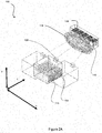
- Figure 2A shows a perspective view of the apparatus 100 of Figure 1 in use when the substance 114 is in a liquid state.
- the apparatus 100 is arranged such that a light signal from the light source 108 is detected by the light detector 110.
- the liquid substance 114 will tend to move with the container 104 but will also move around in an irregular manner within the container 114, i.e. the liquid substance 114 will slosh around within the container 104, as described above.
- the additional movement caused by the liquid substance 114 will cause movement of the container 104, and therefore the movement of the light source 108, to be somewhat irregular or even chaotic.
- the light detector 110 will receive a more irregular or chaotic light signal from the light source 108.
- the light signal will therefore be more spread out in space, typically with an irregular side to side movement which is superimposed on the more regular side to side movement brought about by the reciprocating movement of container 104 and light source 108.
- This is illustrated schematically in Figure 2A by an extended oval light pattern 116 which is received at the light detector 110.
- Figure 2B shows a perspective view of the apparatus of Figure 1 in use when the substance 114 is in a solid state.
- the container 104 When the substance 114 is in a solid state at a time the container 104 is driven to move by an actuator 102, the solid substance 114 will not tend to move within the container 104.
- the container 104 will therefore move largely according to the driving movement of the actuator 102, i.e. in a generally regular manner. Therefore, the light source 108 will also tend to move in the same regular manner as the container 104.
- the light detector 110 therefore receive a regular light signal from the light source 108. This is illustrated schematically in Figure 2B by a circular or slightly oval light pattern 116 which is received at the light detector 110.
- the light detector may be or include at least one light-dependent resistor (LDR) 118.
- LDR light-dependent resistor
- Figures 1 and 2 show the light detector 110 including a plurality of LDRs 118 arranged in a row.
- An LDR is a variable resistor for which the resistance changes in accordance with the light intensity which falls upon it.
- FIG 3 shows an example electrical arrangement 300 for triggering a heating element 302 to heat an environment when a substance has solidified.
- the electric arrangement 300 comprises at least one LDR 304 which receives a light signal from a light source, and a reference resistor 306 for providing a reference for comparison of the light signal detected by an LDR 118/304.
- the arrangement 300 further comprises a power supply 308 to power the heating element 302, and a switch 310, which may be a transistor such as a MOFSET (metal oxide semiconductor field effect transistor), to enable/disable the heating element 302.
- MOFSET metal oxide semiconductor field effect transistor
- the container 104 and thus the light source 108 attached to the container 104 move irregularly. In such a case, at least some of the light from the light source 108 that is incident on the detector 110 may fall outside the bounds of the light detector 110.
- the light that is incident on the detector 110 will tend to spread over a larger number of LDRs 118/304. In any event, as a consequence, the resistance of the or each LDR 118/304 is somewhat low when compared with the resistance of the reference resistor 306. Therefore the switch 310 will not switch on the heating element 302.
- the container 104 when the substance 114 in the container 104 is in a solid state, the container 104, and thus the light source 108 attached to the container 104, move regularly.
- the light signal from the light source 108 will therefore be less spread out and will fall within the bounds of the light detector 110 as a whole and/or any particular LDR 118 receiving light will receive a higher intensity of light.
- the resistance of the LDR 118/304 receiving light is high when compared against the resistance of the reference resistor 306.
- the switch 310 will therefore switch on the heating element 302.
- the electrical arrangement 300 avoids the need for a microcontroller to detect that a substance has solidified and to control operation of a heater.
- the electric arrangement 300 may be part of an electric circuit used within a refrigeration apparatus.
- the heater 302 is located and arranged to reduce or prevent build up of ice on one or more specific components in a refrigeration apparatus, such as the heat exchanger of a refrigeration apparatus.
Landscapes
- Engineering & Computer Science (AREA)
- Chemical & Material Sciences (AREA)
- Combustion & Propulsion (AREA)
- Physics & Mathematics (AREA)
- Mechanical Engineering (AREA)
- Thermal Sciences (AREA)
- General Engineering & Computer Science (AREA)
- Production, Working, Storing, Or Distribution Of Ice (AREA)
- Investigating Or Analyzing Materials Using Thermal Means (AREA)
Description
- The present disclosure relates to an apparatus and method for detecting freezing of a substance.
- So-called frost-free refrigeration apparatus, such as freezers and refrigerators and the like, employ various complex methods for preventing a build up of ice. One example of such a method is periodically heating the freezer or refrigerator to melt any ice that may have formed inside. This process can be wasteful and inefficient.
- According to a first aspect disclosed herein, there is provided an apparatus for detecting freezing of a substance, the apparatus comprising:
- a container, the container containing a substance which has a freezing temperature below which the substance is solid and above which the substance is liquid;
- a light source connected to the container;
- an actuator, the actuator being arranged to move the container; and
- a light detection component; the light detection component being arranged to detect light emitted by the light source;
- the arrangement being such that, when the container is driven to move by the actuator, the amount of light detected by the light detection component varies depending on whether the substance in the container is in a solid state or a liquid state.
- In an example, the light detection component comprises at least one light dependent resistor.
- In an example, the apparatus comprises an electric motor for driving the actuator to vibrate the container.
- In an example, the apparatus comprises a heating element, the arrangement being such that the heating element is triggered to heat when the amount of light detected by the light detection component indicates that the substance in the container is in a solid state.
- In an example, there is provided refrigeration apparatus comprising apparatus as described above. The refrigeration apparatus may be for example a refrigerator or a freezer.
- According to a second aspect disclosed herein, there is provided a method for detecting freezing of a substance, the method comprising:
- driving a container to move by an actuator, the container containing a substance which has a freezing temperature below which the substance is solid and above which the substances is liquid; and
- detecting, by a light detection component, light from a light source, the light source being connected to the container;
- wherein the amount of light detected by the light detection component varies depending on whether the substance in the container is in a solid state or a liquid state.
- In an example, the light detection component comprises at least one light dependent resistor.
- In an example, the method comprises driving the actuator by an electric motor to vibrate the container.
- In an example, the method comprises triggering a heating element to heat when the amount of light detected by the light detection component indicates that the substance in the container is in a solid state.
- In an example, the method is carried out by a refrigeration apparatus the refrigeration apparatus may be for example a refrigerator or a freezer.
- In an example the substance is water which in its liquid state is water or steam and in its solid state is ice.
- To assist understanding of the present disclosure and to show how embodiments may be put into effect, reference is made by way of example to the accompanying drawings in which:
-
Figure 1 shows schematically a side view of a first example of apparatus for detecting freezing of a substance; and -
Figures 2A and2B show schematically perspective views of the apparatus ofFigure 1 in use. - As mentioned previously, refrigeration apparatus, such as for example frost-free freezers and refrigerators and the like, prevent a build-up of ice, particularly on for example the heat exchanger, using relatively complex or inefficient methods. One such method is periodically heating a heater that is located on or near the heat exchanger to melt any ice that may have formed. Often these methods are wasteful, particularly if heaters are used excessively, and inefficient. These methods have no regard for whether ice has actually formed, and simply periodically heat the heat exchanger regardless.
- According to examples described herein, an apparatus is arranged to detect the freezing of a substance, which may be for example water/ice. The apparatus comprises a container. The container contains a substance which has a freezing temperature below which the substance is solid and above which the substance is a liquid. The apparatus also has a light source. The light source is connected to the container. The light source may be connected directly to the container, for example by being mounted on or attached to the container. Alternatively, the light source may be connected indirectly to the container. The apparatus also comprises an actuator. The actuator is arranged to move the container. Further, the apparatus comprises a light detection component. The light detection component being arranged to detect light emitted by the light source. The apparatus is arranged such that, when the container is driven to move by the actuator, the amount of light detected by the light detection component varies depending on whether the substance in the container is in a solid state or a liquid state. Such apparatus may be used in a refrigeration apparatus, such as a refrigerator or a freezer or the like. Such apparatus may also be used in other applications where it may be useful to determine or detect that a substance has solidified.
-
Figure 1 schematically shows a side view of an example of anapparatus 100 for detecting that a substance has solidified. Anactuator 102 is movable so as to drive acontainer 104 to move. In this example, theactuator 102 is connected to thecontainer 104 by arod 106. However, other components and methods may be used to cause theactuator 102 to drive thecontainer 104 to move. Alight source 108 is connected to thecontainer 104. In this example, thelight source 108 is shown directly connected to thecontainer 104. Alternatively, the light source may be mounted indirectly to thecontainer 104, for example by some linkage or the like. Thelight source 108 is arranged to emit light. Thelight source 108 may be for example an LED (light emitting diode). Alight detector 110 is located so as to receive light emitted by thelight source 108. - In use, a
motor 112 moves theactuator 102 which causes thecontainer 104 to move. In one example, the movement of thecontainer 104 is a reciprocating or vibrational movement. This may be for example a back and forth movement of thecontainer 104 or a side to side movement of thecontainer 104 or both. - When the
substance 114 is in a liquid state at the time thecontainer 104 is driven to move, thesubstance 114 will move with thecontainer 104 but will also tend to move within thecontainer 104, typically in a somewhat irregular manner, i.e. theliquid substance 114 will tend to "slosh" around within thecontainer 104. This additional movement of theliquid substance 114 in thecontainer 104 tends to add an additional movement to thecontainer 104 move. The additional movement caused by theliquid substance 114 may occur at the time when theactuator 102 is driving thecontainer 104 to move. Additionally or alternatively, the additional movement caused by theliquid substance 114 in thecontainer 104 may cause thecontainer 104 to continue to move after theactuator 102 has stopped driving thecontainer 104 to move. - In contrast, when the
substance 112 is a solid, the movement of thecontainer 104 will practically only be driven by the movement of theactuator 102. - Accordingly, the movement of the
container 104 will be more irregular or chaotic when thesubstance 112 is in a liquid state than when thesubstance 112 is in a solid state. - The
light source 108 is connected to thecontainer 104. Therefore, when thecontainer 104 is driven to move, thelight source 108 also moves. Alight detector 110 is arranged to receive light from thelight source 108. The nature of the light signal detected by thelight detector 110 will be indicative of the motion of thelight source 108, and therefore of motion of thecontainer 104. -
Figure 2A shows a perspective view of theapparatus 100 ofFigure 1 in use when thesubstance 114 is in a liquid state. Theapparatus 100 is arranged such that a light signal from thelight source 108 is detected by thelight detector 110. When thesubstance 114 is in a liquid state at a time thecontainer 104 is driven to move by anactuator 102, theliquid substance 114 will tend to move with thecontainer 104 but will also move around in an irregular manner within thecontainer 114, i.e. theliquid substance 114 will slosh around within thecontainer 104, as described above. The additional movement caused by theliquid substance 114 will cause movement of thecontainer 104, and therefore the movement of thelight source 108, to be somewhat irregular or even chaotic. At this time, in one example thelight detector 110 will receive a more irregular or chaotic light signal from thelight source 108. The light signal will therefore be more spread out in space, typically with an irregular side to side movement which is superimposed on the more regular side to side movement brought about by the reciprocating movement ofcontainer 104 andlight source 108. This is illustrated schematically inFigure 2A by an extended ovallight pattern 116 which is received at thelight detector 110. -
Figure 2B shows a perspective view of the apparatus ofFigure 1 in use when thesubstance 114 is in a solid state. When thesubstance 114 is in a solid state at a time thecontainer 104 is driven to move by anactuator 102, thesolid substance 114 will not tend to move within thecontainer 104. Thecontainer 104 will therefore move largely according to the driving movement of theactuator 102, i.e. in a generally regular manner. Therefore, thelight source 108 will also tend to move in the same regular manner as thecontainer 104. At this time, thelight detector 110 therefore receive a regular light signal from thelight source 108. This is illustrated schematically inFigure 2B by a circular or slightly ovallight pattern 116 which is received at thelight detector 110. - The light detector may be or include at least one light-dependent resistor (LDR) 118.
Figures 1 and2 show thelight detector 110 including a plurality ofLDRs 118 arranged in a row. An LDR is a variable resistor for which the resistance changes in accordance with the light intensity which falls upon it. -
Figure 3 shows an exampleelectrical arrangement 300 for triggering aheating element 302 to heat an environment when a substance has solidified. Theelectric arrangement 300 comprises at least oneLDR 304 which receives a light signal from a light source, and areference resistor 306 for providing a reference for comparison of the light signal detected by anLDR 118/304. Thearrangement 300 further comprises apower supply 308 to power theheating element 302, and aswitch 310, which may be a transistor such as a MOFSET (metal oxide semiconductor field effect transistor), to enable/disable theheating element 302. - When the
substance 114 in thecontainer 104 is a liquid, thecontainer 104 and thus thelight source 108 attached to thecontainer 104 move irregularly. In such a case, at least some of the light from thelight source 108 that is incident on thedetector 110 may fall outside the bounds of thelight detector 110. Alternatively or additionally, if there areplural LDRs 118, the light that is incident on thedetector 110 will tend to spread over a larger number ofLDRs 118/304. In any event, as a consequence, the resistance of the or eachLDR 118/304 is somewhat low when compared with the resistance of thereference resistor 306. Therefore theswitch 310 will not switch on theheating element 302. - On the other hand, when the
substance 114 in thecontainer 104 is in a solid state, thecontainer 104, and thus thelight source 108 attached to thecontainer 104, move regularly. The light signal from thelight source 108 will therefore be less spread out and will fall within the bounds of thelight detector 110 as a whole and/or anyparticular LDR 118 receiving light will receive a higher intensity of light. As a consequence, the resistance of theLDR 118/304 receiving light is high when compared against the resistance of thereference resistor 306. Theswitch 310 will therefore switch on theheating element 302. - The
electrical arrangement 300 avoids the need for a microcontroller to detect that a substance has solidified and to control operation of a heater. Theelectric arrangement 300 may be part of an electric circuit used within a refrigeration apparatus. In particular, theheater 302 is located and arranged to reduce or prevent build up of ice on one or more specific components in a refrigeration apparatus, such as the heat exchanger of a refrigeration apparatus. - The examples described herein are to be understood as illustrative examples of embodiments of the invention. Further embodiments and examples are envisaged. Any feature described in relation to any one example or embodiment may be used alone or in combination with other features. In addition, any feature described in relation to any one example or embodiment may also be used in combination with one or more features of any other of the examples or embodiments, or any combination of any other of the examples or embodiments. Furthermore, equivalents and modifications not described herein may also be employed within the scope of the invention, which is defined in the claims.
Claims (12)
- An apparatus (100) for detecting freezing of a substance (114), the apparatus (100) comprising:a container (104) the container (104) containing a substance (114) which has a freezing temperature below which the substance (114) is solid and above which the substance (114) is liquid;a light source (108) connected to the container (104);an actuator (102), the actuator (102) being arranged to move the container (104); anda light detection component (110); the light detection component (110) being arranged to detect light emitted by the light source (108);the arrangement being such that, when the container (104) is driven to move by the actuator (102), the amount of light detected by the light detection component (110) varies depending on whether the substance (114) in the container (104) is in a solid state or a liquid state.
- An apparatus (100) according to claim 1, wherein the light detection component (110) comprises at least one light dependent resistor (304).
- An apparatus (100) according to any of claims 1 or 2, comprising an electric motor (112) for driving the actuator (102) to vibrate the container (104).
- An apparatus (100) according to any of claims 1 to 3, comprising a heating element (302), the arrangement being such that the heating element (302) is triggered to heat when the amount of light detected by the light detection component (110) indicates that the substance (114) in the container (104) is in a solid state.
- An apparatus (100) according to any of claims 1 to 4, wherein the substance (114) is water which in its liquid state is water or steam and in its solid state is ice.
- A refrigeration apparatus comprising apparatus (100) according to any of claims 1 to 5.
- A method for detecting freezing of a substance (114), the method comprising:driving a container (104) to move by an actuator (102), the container (104) containing a substance (114) which has a freezing temperature below which the substance (114) is solid and above which the substance (114)s is liquid; anddetecting, by a light detection component (110), light from a light source (108), the light source (108) being connected to the container (104);wherein the amount of light detected by the light detection component (110) varies depending on whether the substance (114) in the container (104) is in a solid state or a liquid state.
- A method according to claim 7, wherein the light detection component (110) comprises at least one light dependent resistor.
- A method according to claim 7 or claim 8, further comprising driving the actuator (102) by an electric motor 112 to vibrate the container (104).
- A method according to any of claims 7 to 9, further comprising triggering a heating element (302) to heat when the amount of light detected by the light detection component (110) indicates that the substance (114) in the container (104) is in a solid state.
- A method according to any of claims 7 to 10, wherein the substance (114) is water which in its liquid state is water or steam and in its solid state is ice.
- A method according to any of claims 7 to 11, the method being carried out in a refrigeration apparatus.
Priority Applications (2)
| Application Number | Priority Date | Filing Date | Title |
|---|---|---|---|
| EP17183083.9A EP3435011B1 (en) | 2017-07-25 | 2017-07-25 | An apparatus and method for detecting freezing of a substance |
| TR2017/11141A TR201711141A2 (en) | 2017-07-25 | 2017-07-28 | AN APPARATUS AND METHOD TO DETECT THE FROST OF A MATERIAL |
Applications Claiming Priority (1)
| Application Number | Priority Date | Filing Date | Title |
|---|---|---|---|
| EP17183083.9A EP3435011B1 (en) | 2017-07-25 | 2017-07-25 | An apparatus and method for detecting freezing of a substance |
Publications (2)
| Publication Number | Publication Date |
|---|---|
| EP3435011A1 true EP3435011A1 (en) | 2019-01-30 |
| EP3435011B1 EP3435011B1 (en) | 2020-03-18 |
Family
ID=59399355
Family Applications (1)
| Application Number | Title | Priority Date | Filing Date |
|---|---|---|---|
| EP17183083.9A Active EP3435011B1 (en) | 2017-07-25 | 2017-07-25 | An apparatus and method for detecting freezing of a substance |
Country Status (2)
| Country | Link |
|---|---|
| EP (1) | EP3435011B1 (en) |
| TR (1) | TR201711141A2 (en) |
Citations (2)
| Publication number | Priority date | Publication date | Assignee | Title |
|---|---|---|---|---|
| JPS5820141U (en) * | 1981-07-29 | 1983-02-07 | 株式会社ボッシュオートモーティブ システム | Freeze detection switch mechanism |
| DE29521065U1 (en) * | 1995-07-06 | 1996-10-24 | Buse, Udo, 33689 Bielefeld | Device for defrosting evaporators for cold rooms |
-
2017
- 2017-07-25 EP EP17183083.9A patent/EP3435011B1/en active Active
- 2017-07-28 TR TR2017/11141A patent/TR201711141A2/en unknown
Patent Citations (2)
| Publication number | Priority date | Publication date | Assignee | Title |
|---|---|---|---|---|
| JPS5820141U (en) * | 1981-07-29 | 1983-02-07 | 株式会社ボッシュオートモーティブ システム | Freeze detection switch mechanism |
| DE29521065U1 (en) * | 1995-07-06 | 1996-10-24 | Buse, Udo, 33689 Bielefeld | Device for defrosting evaporators for cold rooms |
Also Published As
| Publication number | Publication date |
|---|---|
| EP3435011B1 (en) | 2020-03-18 |
| TR201711141A2 (en) | 2019-02-21 |
Similar Documents
| Publication | Publication Date | Title |
|---|---|---|
| US9127875B2 (en) | Variable power defrost heater | |
| US9772138B2 (en) | Cooling box | |
| US11280536B2 (en) | Temperature control of refrigeration cavities in low ambient temperature conditions | |
| WO2015062662A1 (en) | Refrigerator with an improved defrost circuit and method for controlling the refrigerator | |
| EP3435011B1 (en) | An apparatus and method for detecting freezing of a substance | |
| US20140305612A1 (en) | Refrigerator Having Frozen Food Thawing Function | |
| CN103597305A (en) | Single-cycle refrigeration appliance | |
| US20240401867A1 (en) | Refrigerated device with door open sensor fault identification | |
| US20190310004A1 (en) | Method for operating a rotational-speed-variable refrigerant compressor | |
| JP6050159B2 (en) | Cold storage | |
| US4995244A (en) | Refrigerating machine comprising an end-of-defrosting detector | |
| US20160327330A1 (en) | Method and device for controlling a freezing phase in a single-control combined refrigeration appliance, and related refrigeration appliance | |
| EP2859286B1 (en) | A cooling device with two compartments | |
| EP2770282B1 (en) | Method for controlling a refrigerating appliance | |
| KR20200117645A (en) | Unit cooler | |
| US20190162459A1 (en) | Method for operating a variable-speed refrigerant compressor | |
| KR101499499B1 (en) | Frost removing apparatus for evaporator in cooling system using light-emitting diode infra-red detection sensor | |
| RU2007148754A (en) | REFRIGERATING AND / OR FREEZING UNIT | |
| KR200166140Y1 (en) | A rice box | |
| KR100706179B1 (en) | Sink heater of natural convection cooling system for low temperature warehouse | |
| EP2914912B1 (en) | A cooling device comprising a bimetal switch | |
| GB2523686A (en) | Refrigerator having a refrigeration compartment | |
| EP3431905B1 (en) | An apparatus and method for detecting freezing of a substance | |
| KR20090049286A (en) | Refrigeration duct blocking device and method of refrigerator | |
| KR101273703B1 (en) | Prevention control method of rotary compressor backlashing for ice cakes vending machine |
Legal Events
| Date | Code | Title | Description |
|---|---|---|---|
| PUAI | Public reference made under article 153(3) epc to a published international application that has entered the european phase |
Free format text: ORIGINAL CODE: 0009012 |
|
| STAA | Information on the status of an ep patent application or granted ep patent |
Free format text: STATUS: THE APPLICATION HAS BEEN PUBLISHED |
|
| AK | Designated contracting states |
Kind code of ref document: A1 Designated state(s): AL AT BE BG CH CY CZ DE DK EE ES FI FR GB GR HR HU IE IS IT LI LT LU LV MC MK MT NL NO PL PT RO RS SE SI SK SM TR |
|
| AX | Request for extension of the european patent |
Extension state: BA ME |
|
| STAA | Information on the status of an ep patent application or granted ep patent |
Free format text: STATUS: REQUEST FOR EXAMINATION WAS MADE |
|
| 17P | Request for examination filed |
Effective date: 20190730 |
|
| RBV | Designated contracting states (corrected) |
Designated state(s): AL AT BE BG CH CY CZ DE DK EE ES FI FR GB GR HR HU IE IS IT LI LT LU LV MC MK MT NL NO PL PT RO RS SE SI SK SM TR |
|
| GRAP | Despatch of communication of intention to grant a patent |
Free format text: ORIGINAL CODE: EPIDOSNIGR1 |
|
| STAA | Information on the status of an ep patent application or granted ep patent |
Free format text: STATUS: GRANT OF PATENT IS INTENDED |
|
| RIC1 | Information provided on ipc code assigned before grant |
Ipc: F25D 21/02 20060101AFI20190911BHEP |
|
| INTG | Intention to grant announced |
Effective date: 20191016 |
|
| GRAS | Grant fee paid |
Free format text: ORIGINAL CODE: EPIDOSNIGR3 |
|
| GRAA | (expected) grant |
Free format text: ORIGINAL CODE: 0009210 |
|
| STAA | Information on the status of an ep patent application or granted ep patent |
Free format text: STATUS: THE PATENT HAS BEEN GRANTED |
|
| AK | Designated contracting states |
Kind code of ref document: B1 Designated state(s): AL AT BE BG CH CY CZ DE DK EE ES FI FR GB GR HR HU IE IS IT LI LT LU LV MC MK MT NL NO PL PT RO RS SE SI SK SM TR |
|
| REG | Reference to a national code |
Ref country code: GB Ref legal event code: FG4D |
|
| REG | Reference to a national code |
Ref country code: DE Ref legal event code: R096 Ref document number: 602017013157 Country of ref document: DE |
|
| REG | Reference to a national code |
Ref country code: AT Ref legal event code: REF Ref document number: 1246366 Country of ref document: AT Kind code of ref document: T Effective date: 20200415 Ref country code: IE Ref legal event code: FG4D |
|
| PG25 | Lapsed in a contracting state [announced via postgrant information from national office to epo] |
Ref country code: NO Free format text: LAPSE BECAUSE OF FAILURE TO SUBMIT A TRANSLATION OF THE DESCRIPTION OR TO PAY THE FEE WITHIN THE PRESCRIBED TIME-LIMIT Effective date: 20200618 Ref country code: FI Free format text: LAPSE BECAUSE OF FAILURE TO SUBMIT A TRANSLATION OF THE DESCRIPTION OR TO PAY THE FEE WITHIN THE PRESCRIBED TIME-LIMIT Effective date: 20200318 Ref country code: RS Free format text: LAPSE BECAUSE OF FAILURE TO SUBMIT A TRANSLATION OF THE DESCRIPTION OR TO PAY THE FEE WITHIN THE PRESCRIBED TIME-LIMIT Effective date: 20200318 |
|
| REG | Reference to a national code |
Ref country code: NL Ref legal event code: MP Effective date: 20200318 |
|
| PG25 | Lapsed in a contracting state [announced via postgrant information from national office to epo] |
Ref country code: SE Free format text: LAPSE BECAUSE OF FAILURE TO SUBMIT A TRANSLATION OF THE DESCRIPTION OR TO PAY THE FEE WITHIN THE PRESCRIBED TIME-LIMIT Effective date: 20200318 Ref country code: LV Free format text: LAPSE BECAUSE OF FAILURE TO SUBMIT A TRANSLATION OF THE DESCRIPTION OR TO PAY THE FEE WITHIN THE PRESCRIBED TIME-LIMIT Effective date: 20200318 Ref country code: HR Free format text: LAPSE BECAUSE OF FAILURE TO SUBMIT A TRANSLATION OF THE DESCRIPTION OR TO PAY THE FEE WITHIN THE PRESCRIBED TIME-LIMIT Effective date: 20200318 Ref country code: GR Free format text: LAPSE BECAUSE OF FAILURE TO SUBMIT A TRANSLATION OF THE DESCRIPTION OR TO PAY THE FEE WITHIN THE PRESCRIBED TIME-LIMIT Effective date: 20200619 Ref country code: BG Free format text: LAPSE BECAUSE OF FAILURE TO SUBMIT A TRANSLATION OF THE DESCRIPTION OR TO PAY THE FEE WITHIN THE PRESCRIBED TIME-LIMIT Effective date: 20200618 |
|
| REG | Reference to a national code |
Ref country code: LT Ref legal event code: MG4D |
|
| PG25 | Lapsed in a contracting state [announced via postgrant information from national office to epo] |
Ref country code: NL Free format text: LAPSE BECAUSE OF FAILURE TO SUBMIT A TRANSLATION OF THE DESCRIPTION OR TO PAY THE FEE WITHIN THE PRESCRIBED TIME-LIMIT Effective date: 20200318 |
|
| PG25 | Lapsed in a contracting state [announced via postgrant information from national office to epo] |
Ref country code: RO Free format text: LAPSE BECAUSE OF FAILURE TO SUBMIT A TRANSLATION OF THE DESCRIPTION OR TO PAY THE FEE WITHIN THE PRESCRIBED TIME-LIMIT Effective date: 20200318 Ref country code: CZ Free format text: LAPSE BECAUSE OF FAILURE TO SUBMIT A TRANSLATION OF THE DESCRIPTION OR TO PAY THE FEE WITHIN THE PRESCRIBED TIME-LIMIT Effective date: 20200318 Ref country code: EE Free format text: LAPSE BECAUSE OF FAILURE TO SUBMIT A TRANSLATION OF THE DESCRIPTION OR TO PAY THE FEE WITHIN THE PRESCRIBED TIME-LIMIT Effective date: 20200318 Ref country code: LT Free format text: LAPSE BECAUSE OF FAILURE TO SUBMIT A TRANSLATION OF THE DESCRIPTION OR TO PAY THE FEE WITHIN THE PRESCRIBED TIME-LIMIT Effective date: 20200318 Ref country code: PT Free format text: LAPSE BECAUSE OF FAILURE TO SUBMIT A TRANSLATION OF THE DESCRIPTION OR TO PAY THE FEE WITHIN THE PRESCRIBED TIME-LIMIT Effective date: 20200812 Ref country code: SM Free format text: LAPSE BECAUSE OF FAILURE TO SUBMIT A TRANSLATION OF THE DESCRIPTION OR TO PAY THE FEE WITHIN THE PRESCRIBED TIME-LIMIT Effective date: 20200318 Ref country code: SK Free format text: LAPSE BECAUSE OF FAILURE TO SUBMIT A TRANSLATION OF THE DESCRIPTION OR TO PAY THE FEE WITHIN THE PRESCRIBED TIME-LIMIT Effective date: 20200318 Ref country code: IS Free format text: LAPSE BECAUSE OF FAILURE TO SUBMIT A TRANSLATION OF THE DESCRIPTION OR TO PAY THE FEE WITHIN THE PRESCRIBED TIME-LIMIT Effective date: 20200718 |
|
| PGFP | Annual fee paid to national office [announced via postgrant information from national office to epo] |
Ref country code: DE Payment date: 20200729 Year of fee payment: 4 |
|
| REG | Reference to a national code |
Ref country code: AT Ref legal event code: MK05 Ref document number: 1246366 Country of ref document: AT Kind code of ref document: T Effective date: 20200318 |
|
| REG | Reference to a national code |
Ref country code: DE Ref legal event code: R097 Ref document number: 602017013157 Country of ref document: DE |
|
| PLBE | No opposition filed within time limit |
Free format text: ORIGINAL CODE: 0009261 |
|
| STAA | Information on the status of an ep patent application or granted ep patent |
Free format text: STATUS: NO OPPOSITION FILED WITHIN TIME LIMIT |
|
| PG25 | Lapsed in a contracting state [announced via postgrant information from national office to epo] |
Ref country code: AT Free format text: LAPSE BECAUSE OF FAILURE TO SUBMIT A TRANSLATION OF THE DESCRIPTION OR TO PAY THE FEE WITHIN THE PRESCRIBED TIME-LIMIT Effective date: 20200318 Ref country code: ES Free format text: LAPSE BECAUSE OF FAILURE TO SUBMIT A TRANSLATION OF THE DESCRIPTION OR TO PAY THE FEE WITHIN THE PRESCRIBED TIME-LIMIT Effective date: 20200318 Ref country code: IT Free format text: LAPSE BECAUSE OF FAILURE TO SUBMIT A TRANSLATION OF THE DESCRIPTION OR TO PAY THE FEE WITHIN THE PRESCRIBED TIME-LIMIT Effective date: 20200318 Ref country code: DK Free format text: LAPSE BECAUSE OF FAILURE TO SUBMIT A TRANSLATION OF THE DESCRIPTION OR TO PAY THE FEE WITHIN THE PRESCRIBED TIME-LIMIT Effective date: 20200318 |
|
| 26N | No opposition filed |
Effective date: 20201221 |
|
| PG25 | Lapsed in a contracting state [announced via postgrant information from national office to epo] |
Ref country code: MC Free format text: LAPSE BECAUSE OF FAILURE TO SUBMIT A TRANSLATION OF THE DESCRIPTION OR TO PAY THE FEE WITHIN THE PRESCRIBED TIME-LIMIT Effective date: 20200318 Ref country code: PL Free format text: LAPSE BECAUSE OF FAILURE TO SUBMIT A TRANSLATION OF THE DESCRIPTION OR TO PAY THE FEE WITHIN THE PRESCRIBED TIME-LIMIT Effective date: 20200318 |
|
| REG | Reference to a national code |
Ref country code: CH Ref legal event code: PL |
|
| REG | Reference to a national code |
Ref country code: BE Ref legal event code: MM Effective date: 20200731 |
|
| PG25 | Lapsed in a contracting state [announced via postgrant information from national office to epo] |
Ref country code: FR Free format text: LAPSE BECAUSE OF NON-PAYMENT OF DUE FEES Effective date: 20200731 Ref country code: CH Free format text: LAPSE BECAUSE OF NON-PAYMENT OF DUE FEES Effective date: 20200731 Ref country code: LI Free format text: LAPSE BECAUSE OF NON-PAYMENT OF DUE FEES Effective date: 20200731 Ref country code: LU Free format text: LAPSE BECAUSE OF NON-PAYMENT OF DUE FEES Effective date: 20200725 |
|
| PG25 | Lapsed in a contracting state [announced via postgrant information from national office to epo] |
Ref country code: SI Free format text: LAPSE BECAUSE OF FAILURE TO SUBMIT A TRANSLATION OF THE DESCRIPTION OR TO PAY THE FEE WITHIN THE PRESCRIBED TIME-LIMIT Effective date: 20200318 Ref country code: BE Free format text: LAPSE BECAUSE OF NON-PAYMENT OF DUE FEES Effective date: 20200731 |
|
| PG25 | Lapsed in a contracting state [announced via postgrant information from national office to epo] |
Ref country code: IE Free format text: LAPSE BECAUSE OF NON-PAYMENT OF DUE FEES Effective date: 20200725 |
|
| REG | Reference to a national code |
Ref country code: DE Ref legal event code: R119 Ref document number: 602017013157 Country of ref document: DE |
|
| GBPC | Gb: european patent ceased through non-payment of renewal fee |
Effective date: 20210725 |
|
| PG25 | Lapsed in a contracting state [announced via postgrant information from national office to epo] |
Ref country code: GB Free format text: LAPSE BECAUSE OF NON-PAYMENT OF DUE FEES Effective date: 20210725 Ref country code: DE Free format text: LAPSE BECAUSE OF NON-PAYMENT OF DUE FEES Effective date: 20220201 |
|
| PG25 | Lapsed in a contracting state [announced via postgrant information from national office to epo] |
Ref country code: MT Free format text: LAPSE BECAUSE OF FAILURE TO SUBMIT A TRANSLATION OF THE DESCRIPTION OR TO PAY THE FEE WITHIN THE PRESCRIBED TIME-LIMIT Effective date: 20200318 Ref country code: CY Free format text: LAPSE BECAUSE OF FAILURE TO SUBMIT A TRANSLATION OF THE DESCRIPTION OR TO PAY THE FEE WITHIN THE PRESCRIBED TIME-LIMIT Effective date: 20200318 |
|
| PG25 | Lapsed in a contracting state [announced via postgrant information from national office to epo] |
Ref country code: MK Free format text: LAPSE BECAUSE OF FAILURE TO SUBMIT A TRANSLATION OF THE DESCRIPTION OR TO PAY THE FEE WITHIN THE PRESCRIBED TIME-LIMIT Effective date: 20200318 Ref country code: AL Free format text: LAPSE BECAUSE OF FAILURE TO SUBMIT A TRANSLATION OF THE DESCRIPTION OR TO PAY THE FEE WITHIN THE PRESCRIBED TIME-LIMIT Effective date: 20200318 |
|
| PGFP | Annual fee paid to national office [announced via postgrant information from national office to epo] |
Ref country code: TR Payment date: 20250724 Year of fee payment: 9 |