EP3434914A1 - Fluidic device - Google Patents
Fluidic device Download PDFInfo
- Publication number
- EP3434914A1 EP3434914A1 EP18181190.2A EP18181190A EP3434914A1 EP 3434914 A1 EP3434914 A1 EP 3434914A1 EP 18181190 A EP18181190 A EP 18181190A EP 3434914 A1 EP3434914 A1 EP 3434914A1
- Authority
- EP
- European Patent Office
- Prior art keywords
- control
- output
- fluid flow
- channel
- flow
- Prior art date
- Legal status (The legal status is an assumption and is not a legal conclusion. Google has not performed a legal analysis and makes no representation as to the accuracy of the status listed.)
- Withdrawn
Links
- 239000012530 fluid Substances 0.000 claims abstract description 104
- 239000003990 capacitor Substances 0.000 claims description 7
- 238000002485 combustion reaction Methods 0.000 description 3
- 230000001141 propulsive effect Effects 0.000 description 3
- 230000000694 effects Effects 0.000 description 2
- 230000006835 compression Effects 0.000 description 1
- 238000007906 compression Methods 0.000 description 1
- 239000000446 fuel Substances 0.000 description 1
- 230000000977 initiatory effect Effects 0.000 description 1
- 238000000034 method Methods 0.000 description 1
- 239000000203 mixture Substances 0.000 description 1
- 238000012986 modification Methods 0.000 description 1
- 230000004048 modification Effects 0.000 description 1
Images


Classifications
-
- B—PERFORMING OPERATIONS; TRANSPORTING
- B64—AIRCRAFT; AVIATION; COSMONAUTICS
- B64C—AEROPLANES; HELICOPTERS
- B64C21/00—Influencing air flow over aircraft surfaces by affecting boundary layer flow
- B64C21/02—Influencing air flow over aircraft surfaces by affecting boundary layer flow by use of slot, ducts, porous areas or the like
-
- F—MECHANICAL ENGINEERING; LIGHTING; HEATING; WEAPONS; BLASTING
- F15—FLUID-PRESSURE ACTUATORS; HYDRAULICS OR PNEUMATICS IN GENERAL
- F15B—SYSTEMS ACTING BY MEANS OF FLUIDS IN GENERAL; FLUID-PRESSURE ACTUATORS, e.g. SERVOMOTORS; DETAILS OF FLUID-PRESSURE SYSTEMS, NOT OTHERWISE PROVIDED FOR
- F15B21/00—Common features of fluid actuator systems; Fluid-pressure actuator systems or details thereof, not covered by any other group of this subclass
- F15B21/12—Fluid oscillators or pulse generators
-
- F—MECHANICAL ENGINEERING; LIGHTING; HEATING; WEAPONS; BLASTING
- F15—FLUID-PRESSURE ACTUATORS; HYDRAULICS OR PNEUMATICS IN GENERAL
- F15C—FLUID-CIRCUIT ELEMENTS PREDOMINANTLY USED FOR COMPUTING OR CONTROL PURPOSES
- F15C1/00—Circuit elements having no moving parts
- F15C1/002—Circuit elements having no moving parts for controlling engines, turbines, compressors (starting, speed regulation, temperature control or the like)
-
- F—MECHANICAL ENGINEERING; LIGHTING; HEATING; WEAPONS; BLASTING
- F15—FLUID-PRESSURE ACTUATORS; HYDRAULICS OR PNEUMATICS IN GENERAL
- F15C—FLUID-CIRCUIT ELEMENTS PREDOMINANTLY USED FOR COMPUTING OR CONTROL PURPOSES
- F15C1/00—Circuit elements having no moving parts
- F15C1/08—Boundary-layer devices, e.g. wall-attachment amplifiers coanda effect
- F15C1/10—Boundary-layer devices, e.g. wall-attachment amplifiers coanda effect for digital operation, e.g. to form a logical flip-flop, OR-gate, NOR-gate, AND-gate; Comparators; Pulse generators
-
- F—MECHANICAL ENGINEERING; LIGHTING; HEATING; WEAPONS; BLASTING
- F15—FLUID-PRESSURE ACTUATORS; HYDRAULICS OR PNEUMATICS IN GENERAL
- F15C—FLUID-CIRCUIT ELEMENTS PREDOMINANTLY USED FOR COMPUTING OR CONTROL PURPOSES
- F15C1/00—Circuit elements having no moving parts
- F15C1/14—Stream-interaction devices; Momentum-exchange devices, e.g. operating by exchange between two orthogonal fluid jets ; Proportional amplifiers
-
- F—MECHANICAL ENGINEERING; LIGHTING; HEATING; WEAPONS; BLASTING
- F15—FLUID-PRESSURE ACTUATORS; HYDRAULICS OR PNEUMATICS IN GENERAL
- F15C—FLUID-CIRCUIT ELEMENTS PREDOMINANTLY USED FOR COMPUTING OR CONTROL PURPOSES
- F15C1/00—Circuit elements having no moving parts
- F15C1/16—Vortex devices, i.e. devices in which use is made of the pressure drop associated with vortex motion in a fluid
-
- F—MECHANICAL ENGINEERING; LIGHTING; HEATING; WEAPONS; BLASTING
- F15—FLUID-PRESSURE ACTUATORS; HYDRAULICS OR PNEUMATICS IN GENERAL
- F15C—FLUID-CIRCUIT ELEMENTS PREDOMINANTLY USED FOR COMPUTING OR CONTROL PURPOSES
- F15C1/00—Circuit elements having no moving parts
- F15C1/22—Oscillators
-
- B—PERFORMING OPERATIONS; TRANSPORTING
- B64—AIRCRAFT; AVIATION; COSMONAUTICS
- B64C—AEROPLANES; HELICOPTERS
- B64C2230/00—Boundary layer controls
- B64C2230/04—Boundary layer controls by actively generating fluid flow
-
- B—PERFORMING OPERATIONS; TRANSPORTING
- B64—AIRCRAFT; AVIATION; COSMONAUTICS
- B64C—AEROPLANES; HELICOPTERS
- B64C2230/00—Boundary layer controls
- B64C2230/06—Boundary layer controls by explicitly adjusting fluid flow, e.g. by using valves, variable aperture or slot areas, variable pump action or variable fluid pressure
-
- B—PERFORMING OPERATIONS; TRANSPORTING
- B64—AIRCRAFT; AVIATION; COSMONAUTICS
- B64C—AEROPLANES; HELICOPTERS
- B64C2230/00—Boundary layer controls
- B64C2230/18—Boundary layer controls by using small jets that make the fluid flow oscillate
Definitions
- the present disclosure relates to a fluidic device for providing analogue output control.
- Fluidic components were used in the 1950s for building fluidic-based computers. However with invention of the transistor these had gone obsolete by the 1960s. Since then the use of fluidic components has been limited to niche applications such as the control of variable stator vanes on aero gas turbine engines (see for example US 4252498 ).
- a component that operates on this principle is a fluidic diverter, shown schematically in Figure 1 .
- the diverter has a main channel 1, a first control channel 2 and a second control channel 3.
- the diverter further has a first output channel 4 and a second output channel 5.
- Flows from the first and second control channels arrive in the diverter transversely to a flow from the main channel.
- suitable control of the transverse control flows which may be less than 20% of the mass flow rate of the main flow, an output flow can be switched between the first and the second output channels.
- An advantage of such a component is the lack of moving parts, making it suitable for use in harsh environments, such as jet engines and nuclear reactors.
- a disadvantage, however, is that it is a digital component, which is unable to vary the output flow in a continuous manner.
- FIG. 2 shows schematically at left another known fluidic device, in this case a vortex amplifier 6, and at right a plot of amplifier output against time.
- the amplifier has a primary flow source, a primary flow sink and a control valve 7 which allows servo fluid into the amplifier when opened.
- the fluid from the primary flow passes in a radial direction of the amplifier to the sink at a relatively high flow rate. Opening the control valve introduce the servo fluid, which generates a vortex in the amplifier.
- the resulting vortex produces an increased resistance to radial flow, and thus throttles the primary flow out of the sink to a leakage level.
- the output from the amplifier is again essentially binary.
- the present disclosure provides a fluidic device that extends the operation of known devices so as to provide an output which is suitable for use in analogue control, and thus enables greater levels of control and performance.
- the present disclosure provides a fluidic device for providing analogue output control, the device including:
- the fluidic device may be adapted for controlling a gas turbine engine component(s).
- the controlled gas turbine engine component(s) can be a bleed valve, variable guide vanes, variable stator vanes, or an air system providing turbine tip clearance control.
- the present disclosure provides a gas turbine engine having one or more fluidic devices according to the first aspect for controlling respective components of the engine.
- the first control channel may be configured such that the input fluid flow therefrom carries a saw tooth pressure wave signal.
- the reference mass flow rate may vary with engine cycle.
- the main channel may be configured such that the input fluid flow therefrom is at a constant reference mass flow rate.
- the first and second control channels are configured such that the input fluid flows therefrom are transverse to the input fluid from the main channel.
- the first and second control channels are configured such that the input fluid flows therefrom impinge at the same point on the input fluid from the main channel.
- the first and second control channels are configured such that the input fluid flows therefrom are opposed to each other.
- the first control channel may extend in flow series through a fluidic oscillator and a fluidic capacitor to produce the oscillating pressure wave signal.
- the flow regulator may be controllable to continuously and smoothly vary the mass flow rate of the input fluid flow from the second control channel.
- the flow regulator can be a modulating valve.
- the fluidic device may be configured such that input mass flow rates to the main, first control and second control channels are identical.
- the comparator may be a fluidic diverter having first and second output channels and the output fluid flow may be a first output fluid flow taken from the first output channel, the input fluid flows from the first control and the second control channels acting in combination on the input fluid flow from the main channel to provide the first output fluid flow with the pulse width modulation mass flow rate characteristic.
- a second output fluid flow from the second output channel generally has an opposite pulse width modulation mass flow rate characteristic to the first output fluid flow.
- the output channels are configured such that the output fluid flows which flow therethrough are taken from the same point on the input fluid from the main channel.
- the output channels are configured such that the output fluid flows diverge at angles from the direction of the input fluid from the main channel. The angles are typically equal and opposite angles.
- a second output fluid flow may be taken from the second output channel
- the device may further include a feedback loop from the second output channel to the second control channel
- the flow regulator is controllable to vary a proportion of the mass flow rate of a second output fluid flow entering the second control channel from the second output channel via the feedback loop.
- Such a feedback loop may typically be configured to take from 5% to 20% of the second output fluid flow from the second output channel.
- the fluidic device may further include an actuator comprising a piston which is movable in a piston chamber, the piston chamber to one side of the piston receiving the first output fluid flow, and the piston to the other side of the piston receiving a second output fluid flow taken from the second output channel, whereby the position of the piston in the chamber is controllable by varying pulse widths in the pulse width modulation mass flow rate characteristic.
- the fluidic device may then further have a feedback control loop which controls the flow regulator to vary the mass flow rate of the input fluid flow from the second control channel on the basis of the piston position.
- a fluidic device in which the comparator is a fluidic diverter may further include a vortex amplifier having a source for receiving a flow of a primary fluid into the vortex amplifier, a sink through which the primary fluid leaves the vortex amplifier, and a control port for introducing a control fluid flow into the vortex amplifier, wherein the vortex amplifier is configured such that a relatively high mass flow rate of the control fluid forms a vortex from the primary fluid between the source and the sink to set a flow of the primary fluid from the sink to a relatively low level, and a relatively low or zero mass flow rate of the control fluid reduces or eliminates the vortex to set the flow of the primary fluid from the sink to a relatively high level; wherein the first output fluid flow from the fluidic diverter forms the control fluid flow into the vortex amplifier.
- this option enables fast switching on and off of the vortex amplifier, which in turn enables it to effectively operate as an analogue device with a range of flows of the primary fluid from the sink rather than binary flows.
- the fluidic device may be a pneumatic device.
- a ducted fan gas turbine engine is generally indicated at 10 and has a principal and rotational axis X-X.
- the engine comprises, in axial flow series, an air intake 11, a propulsive fan 12, an intermediate pressure compressor 13, a high-pressure compressor 14, combustion equipment 15, a high-pressure turbine 16, an intermediate pressure turbine 17, a low-pressure turbine 18 and a core engine exhaust nozzle 19.
- a nacelle 21 generally surrounds the engine 10 and defines the intake 11, a bypass duct 22 and a bypass exhaust nozzle 23.
- air entering the intake 11 is accelerated by the fan 12 to produce two air flows: a first air flow A into the intermediate-pressure compressor 13 and a second airflow B which passes through the bypass duct 22 to provide propulsive thrust.
- the intermediate-pressure compressor 13 compresses the air flow A directed into it before delivering that air to the high-pressure compressor 14 where further compression takes place.
- the compressed air exhausted from the high-pressure compressor 14 is directed into the combustion equipment 15 where it is mixed with fuel and the mixture combusted.
- the resultant hot combustion products then expand through, and thereby drive the high, intermediate and low-pressure turbines 16, 17, 18 before being exhausted through the nozzle 19 to provide additional propulsive thrust.
- the high, intermediate and low-pressure turbines respectively drive the high and intermediate-pressure compressors 14, 13 and the fan 12 by suitable interconnecting shafts.
- gas turbine engines to which the present disclosure may be applied may have alternative configurations.
- such engines may have an alternative number of interconnecting shafts (e.g. two) and/or an alternative number of compressors and/or turbines.
- the engine may comprise a gearbox provided in the drive train from a turbine to a compressor and/or fan.
- the engine 10 has components such as bleed valves, variable guide vanes, variable stator vanes, and air systems for providing turbine tip clearance control. Such components may be controlled using an analogue control signal derived from the output fluid of a fluidic device.
- a fluidic device can operate reliably in the harsh environment of the engine.
- FIG 4 shows schematically the fluidic device 30.
- a fluid diverter 31 of the type shown in Figure 1 functions as a comparator, receiving respective input fluid flows from a main channel 32, a first control channel 33 and a second control channel 34, and producing an output fluid flow with a pulse width modulation (PWM) mass flow rate characteristic from a first one of its two output channels.
- PWM pulse width modulation
- the main channel 32, first control channel 33 and second control channel 34 can receive fluid at an identical input mass flow rate.
- the first control channel 33 has, in flow series, a fluidic oscillator 35 and a fluidic capacitor 36.
- the fluidic oscillator generates stable, constant frequency mass flow rate pulses. See for example, V. Tesa ⁇ , High-frequency fluidic oscillator, Sensors and Actuators A: Physical, volume 234, 1 October 2015, pages 158-167 .
- the fluidic capacitor then filters the oscillator output to create an oscillating pressure wave signal, such as a saw tooth pressure wave signal.
- the capacitor can be implemented as an appropriately sized pressure chamber with an orifice. See for example, K.
- the second control channel 34 has a flow regulator 37, e.g. in the form of a pneumatic, modulating valve, which is used to controllably vary the mass flow rate of the input fluid flow to the fluid diverter 31 from the second control channel.
- the mass flow rate from the second control channel determines the widths of the PWM mass flow rate pulses from the first output channel.
- a first output fluid flow from the fluid diverter 31 is the flow from the first output channel, which flow is set ON (corresponding to initiation of a PWM pulse) when the diverter receives a pressure spike from the first control channel 33.
- the first output fluid flow is kept switched ON (corresponding to the width of a PWM pulse) for a duration that is determined by the mass flow rate of the input fluid flow from the second control channel 34.
- the second output fluid flow from the second output channel is ON, producing an opposite (inverse) PWM mass flow rate characteristic to the first output fluid flow.
- the PWM mass flow rate pulses can be modulated to produce an average mass flow rate value that is smoothly and continuously variable, and suitable for providing analogue control.
- narrow pulses produce a low average mass flow rate and wide pulses a high average mass flow rate.
- the pulse frequency i.e. ON-OFF switching speed
- the pulse frequency is determined depending on the size of the load (i.e. the load volume) such that during the OFF state the load pressure does not drop significantly (e.g. ⁇ 1%).
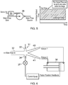
- FIG. 5 shows schematically at left a vortex amplifier 38 having the fluidic device 30 in place of a conventional control valve, and at right a graph of amplifier output against time with the hatched area showing how the output from the primary flow sink can be set to any value within a range at any given moment.
- Figure 6 shows schematically the fluid diverter 31 of the fluidic device 30 connected to an actuator in the form of a pneumatic piston arrangement 39 in which, by connecting one of the output channels 40 of the diverter to the chamber on one side of the piston and connecting the other output channel 41 of the diverter to the chamber on opposite side of the piston, the direction of travel of the piston can be controlled by the duration of the ON periods relative to the OFF periods.
- feedback of piston position to the flow regulator 37 of the second control channel 34 can be used to provide closed loop control of piston movement. In this way, by adjusting a control setting of the flow regulator (i.e. effectively setting its "gain"), the piston position can be correspondingly adjusted.
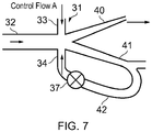
- the flow control of the second control channel 34 may be via a direct feedback loop 42 from the second output channel 41.
- the flow regulator 37 can be set such that the feedback loop typically takes from 5% to 20% of the second output fluid flow from the second output channel 41.
- a high mass flow rate i.e. a PWM pulse
- the input fluid flow from the main channel 32 is pushed towards the second output channel 41, upon which the feedback tries to push the input fluid flow from the main channel back to the first output channel.
- the input fluid flow from the main channel stays directed to the second output channel until the first input channel pressure spike reduces below a given value, as determined by the feedback from the second input channel moderated by the flow regulator setting.
- the fluidic device is advantageously applicable to other situations - particularly harsh environments where electronic control may not be suitable.
- possible uses can be found in fields diverse as marine, automotive, industrial, processing industry, nuclear etc.
Landscapes
- Engineering & Computer Science (AREA)
- General Engineering & Computer Science (AREA)
- Physics & Mathematics (AREA)
- Fluid Mechanics (AREA)
- Mechanical Engineering (AREA)
- Theoretical Computer Science (AREA)
- Chemical & Material Sciences (AREA)
- Combustion & Propulsion (AREA)
- Analytical Chemistry (AREA)
- Aviation & Aerospace Engineering (AREA)
- Control Of Turbines (AREA)
Abstract
A fluidic device for providing analogue output control includes a main channel, a first control channel and a second control channel. The fluidic device further includes a comparator which receives respective input fluid flows from the main, the first control and the second control channels. The first control channel is configured such that the input fluid flow therefrom carries an oscillating pressure wave signal, the second control channel includes a flow regulator which is controllable to vary the mass flow rate of the input fluid flow from the second control channel, and the main channel is configured such that the input fluid flow therefrom is at a reference mass flow rate. The comparator is configured such that the input fluid flows from the first control and the second control channels act in combination on the input fluid flow from the main channel to produce an output fluid flow from the comparator having a pulse width modulation mass flow rate characteristic.
Description
- The present disclosure relates to a fluidic device for providing analogue output control.
- Fluidic components were used in the 1950s for building fluidic-based computers. However with invention of the transistor these had gone obsolete by the 1960s. Since then the use of fluidic components has been limited to niche applications such as the control of variable stator vanes on aero gas turbine engines (see for example
US 4252498 ). - Many fluidic devices are known, but common ones are based on the Coanda effect, which describes the tendency of a jet flow near a wall to attach to that wall through an entrainment process. A component that operates on this principle is a fluidic diverter, shown schematically in
Figure 1 . The diverter has amain channel 1, afirst control channel 2 and a second control channel 3. The diverter further has afirst output channel 4 and asecond output channel 5. Flows from the first and second control channels arrive in the diverter transversely to a flow from the main channel. By suitable control of the transverse control flows, which may be less than 20% of the mass flow rate of the main flow, an output flow can be switched between the first and the second output channels. Such a diverter can be thought as an amplifier with a typical gain >= 5. - An advantage of such a component is the lack of moving parts, making it suitable for use in harsh environments, such as jet engines and nuclear reactors. A disadvantage, however, is that it is a digital component, which is unable to vary the output flow in a continuous manner.
-
Figure 2 shows schematically at left another known fluidic device, in this case avortex amplifier 6, and at right a plot of amplifier output against time. The amplifier has a primary flow source, a primary flow sink and acontrol valve 7 which allows servo fluid into the amplifier when opened. In the absence of servo fluid through the control valve, the fluid from the primary flow passes in a radial direction of the amplifier to the sink at a relatively high flow rate. Opening the control valve introduce the servo fluid, which generates a vortex in the amplifier. The resulting vortex produces an increased resistance to radial flow, and thus throttles the primary flow out of the sink to a leakage level. Thus the output from the amplifier is again essentially binary. - In general terms, the present disclosure provides a fluidic device that extends the operation of known devices so as to provide an output which is suitable for use in analogue control, and thus enables greater levels of control and performance.
- Accordingly, in a first aspect, the present disclosure provides a fluidic device for providing analogue output control, the device including:
- a main channel, a first control channel and a second control channel, and
- a comparator which receives respective input fluid flows from the main, the first control and the second control channels;
- wherein the first control channel is configured such that the input fluid flow therefrom carries an oscillating pressure wave signal, the second control channel includes a flow regulator which is controllable to vary the mass flow rate of the input fluid flow from the second control channel, and the main channel is configured such that the input fluid flow therefrom is at a reference mass flow rate; and
- wherein the comparator is configured such that the input fluid flows from the first control and the second control channels act in combination on the input fluid flow from the main channel to produce an output fluid flow from the comparator having a pulse width modulation mass flow rate characteristic.
- Such a characteristic can be usable as an analogue control signal. The fluidic device may be adapted for controlling a gas turbine engine component(s). For example, the controlled gas turbine engine component(s) can be a bleed valve, variable guide vanes, variable stator vanes, or an air system providing turbine tip clearance control.
- Accordingly, in a second aspect, the present disclosure provides a gas turbine engine having one or more fluidic devices according to the first aspect for controlling respective components of the engine.
- Optional features of the present disclosure will now be set out. These are applicable singly or in any combination with any aspect of the present disclosure.
- Conveniently, the first control channel may be configured such that the input fluid flow therefrom carries a saw tooth pressure wave signal.
- In the context of a gas turbine engine, the reference mass flow rate may vary with engine cycle. However, conveniently, the main channel may be configured such that the input fluid flow therefrom is at a constant reference mass flow rate.
- Typically, the first and second control channels are configured such that the input fluid flows therefrom are transverse to the input fluid from the main channel. Typically, the first and second control channels are configured such that the input fluid flows therefrom impinge at the same point on the input fluid from the main channel. Typically, the first and second control channels are configured such that the input fluid flows therefrom are opposed to each other.
- The first control channel may extend in flow series through a fluidic oscillator and a fluidic capacitor to produce the oscillating pressure wave signal.
- The flow regulator may be controllable to continuously and smoothly vary the mass flow rate of the input fluid flow from the second control channel. For example, the flow regulator can be a modulating valve.
- The fluidic device may be configured such that input mass flow rates to the main, first control and second control channels are identical.
- The comparator may be a fluidic diverter having first and second output channels and the output fluid flow may be a first output fluid flow taken from the first output channel, the input fluid flows from the first control and the second control channels acting in combination on the input fluid flow from the main channel to provide the first output fluid flow with the pulse width modulation mass flow rate characteristic. In such an arrangement, a second output fluid flow from the second output channel generally has an opposite pulse width modulation mass flow rate characteristic to the first output fluid flow. Typically, the output channels are configured such that the output fluid flows which flow therethrough are taken from the same point on the input fluid from the main channel. Typically, the output channels are configured such that the output fluid flows diverge at angles from the direction of the input fluid from the main channel. The angles are typically equal and opposite angles.
- According to one option when the comparator is a fluidic diverter, a second output fluid flow may be taken from the second output channel, the device may further include a feedback loop from the second output channel to the second control channel, and the flow regulator is controllable to vary a proportion of the mass flow rate of a second output fluid flow entering the second control channel from the second output channel via the feedback loop. Such a feedback loop may typically be configured to take from 5% to 20% of the second output fluid flow from the second output channel.
- Additionally or alternatively when the comparator is a fluidic diverter, the fluidic device may further include an actuator comprising a piston which is movable in a piston chamber, the piston chamber to one side of the piston receiving the first output fluid flow, and the piston to the other side of the piston receiving a second output fluid flow taken from the second output channel, whereby the position of the piston in the chamber is controllable by varying pulse widths in the pulse width modulation mass flow rate characteristic. The fluidic device may then further have a feedback control loop which controls the flow regulator to vary the mass flow rate of the input fluid flow from the second control channel on the basis of the piston position.
- According to another option, a fluidic device in which the comparator is a fluidic diverter may further include a vortex amplifier having a source for receiving a flow of a primary fluid into the vortex amplifier, a sink through which the primary fluid leaves the vortex amplifier, and a control port for introducing a control fluid flow into the vortex amplifier, wherein the vortex amplifier is configured such that a relatively high mass flow rate of the control fluid forms a vortex from the primary fluid between the source and the sink to set a flow of the primary fluid from the sink to a relatively low level, and a relatively low or zero mass flow rate of the control fluid reduces or eliminates the vortex to set the flow of the primary fluid from the sink to a relatively high level; wherein the first output fluid flow from the fluidic diverter forms the control fluid flow into the vortex amplifier. When the comparator is a fluidic diverter and the first output fluid flow has a pulse width modulation mass flow rate characteristic, this option enables fast switching on and off of the vortex amplifier, which in turn enables it to effectively operate as an analogue device with a range of flows of the primary fluid from the sink rather than binary flows.
- The fluidic device may be a pneumatic device.
- Embodiments of the present disclosure will now be described by way of example with reference to the accompanying drawings in which:
-
Figure 1 shows schematically a fluidic diverter based on the Coanda effect; -
Figure 2 shows schematically at left a vortex amplifier, and at right a plot of vortex amplifier output against time; -
Figure 3 shows a longitudinal cross-section through a ducted fan gas turbine engine; -
Figure 4 shows schematically a fluidic device for controlling a component(s) of the engine ofFigure 3 ; -
Figure 5 shows schematically at left a vortex amplifier having the fluidic device ofFigure 4 as a controller, and at right a graph of vortex amplifier output against time; -
Figure 6 shows schematically a fluid diverter of the fluidic device ofFigure 4 connected to a pneumatic piston type arrangement; and -
Figure 7 shows schematically a variant fluidic device. - With reference to
Figure 3 , a ducted fan gas turbine engine is generally indicated at 10 and has a principal and rotational axis X-X. The engine comprises, in axial flow series, anair intake 11, apropulsive fan 12, anintermediate pressure compressor 13, a high-pressure compressor 14,combustion equipment 15, a high-pressure turbine 16, anintermediate pressure turbine 17, a low-pressure turbine 18 and a coreengine exhaust nozzle 19. Anacelle 21 generally surrounds theengine 10 and defines theintake 11, abypass duct 22 and abypass exhaust nozzle 23. - During operation, air entering the
intake 11 is accelerated by thefan 12 to produce two air flows: a first air flow A into the intermediate-pressure compressor 13 and a second airflow B which passes through thebypass duct 22 to provide propulsive thrust. The intermediate-pressure compressor 13 compresses the air flow A directed into it before delivering that air to the high-pressure compressor 14 where further compression takes place. - The compressed air exhausted from the high-
pressure compressor 14 is directed into thecombustion equipment 15 where it is mixed with fuel and the mixture combusted. The resultant hot combustion products then expand through, and thereby drive the high, intermediate and low-pressure turbines nozzle 19 to provide additional propulsive thrust. The high, intermediate and low-pressure turbines respectively drive the high and intermediate-pressure compressors fan 12 by suitable interconnecting shafts. - Other gas turbine engines to which the present disclosure may be applied may have alternative configurations. By way of example such engines may have an alternative number of interconnecting shafts (e.g. two) and/or an alternative number of compressors and/or turbines. Further the engine may comprise a gearbox provided in the drive train from a turbine to a compressor and/or fan.
- The
engine 10 has components such as bleed valves, variable guide vanes, variable stator vanes, and air systems for providing turbine tip clearance control. Such components may be controlled using an analogue control signal derived from the output fluid of a fluidic device. Advantageously, such a device can operate reliably in the harsh environment of the engine. -
Figure 4 shows schematically thefluidic device 30. Afluid diverter 31 of the type shown inFigure 1 functions as a comparator, receiving respective input fluid flows from amain channel 32, afirst control channel 33 and asecond control channel 34, and producing an output fluid flow with a pulse width modulation (PWM) mass flow rate characteristic from a first one of its two output channels. - Conveniently, the
main channel 32,first control channel 33 andsecond control channel 34 can receive fluid at an identical input mass flow rate. - The
first control channel 33 has, in flow series, afluidic oscillator 35 and afluidic capacitor 36. The fluidic oscillator generates stable, constant frequency mass flow rate pulses. See for example, V. Tesař, High-frequency fluidic oscillator, Sensors and Actuators A: Physical, . The fluidic capacitor then filters the oscillator output to create an oscillating pressure wave signal, such as a saw tooth pressure wave signal. The capacitor can be implemented as an appropriately sized pressure chamber with an orifice. See for example, K. Xu et al., Fluidic capacitor-based, self-contained and self-powered microfluidic chip, 15th International Conference on Miniaturized Systems for Chemistry and Life Sciences, October 2-6, 2011, Seattle, Washington, USA, pages 233-235. The fluidic oscillator and the fluidic capacitor preferably have no moving parts. Another option for producing the oscillating wave signal is to use a Hartmann or Galton whistle device. - The
second control channel 34 has aflow regulator 37, e.g. in the form of a pneumatic, modulating valve, which is used to controllably vary the mass flow rate of the input fluid flow to thefluid diverter 31 from the second control channel. In particular, the mass flow rate from the second control channel determines the widths of the PWM mass flow rate pulses from the first output channel. - Thus a first output fluid flow from the
fluid diverter 31 is the flow from the first output channel, which flow is set ON (corresponding to initiation of a PWM pulse) when the diverter receives a pressure spike from thefirst control channel 33. The first output fluid flow is kept switched ON (corresponding to the width of a PWM pulse) for a duration that is determined by the mass flow rate of the input fluid flow from thesecond control channel 34. Conversely, when the first output fluid flow is OFF (i.e. between its PWM pulses), the second output fluid flow from the second output channel is ON, producing an opposite (inverse) PWM mass flow rate characteristic to the first output fluid flow. - The PWM mass flow rate pulses can be modulated to produce an average mass flow rate value that is smoothly and continuously variable, and suitable for providing analogue control. Thus narrow pulses produce a low average mass flow rate and wide pulses a high average mass flow rate. The pulse frequency (i.e. ON-OFF switching speed) is determined depending on the size of the load (i.e. the load volume) such that during the OFF state the load pressure does not drop significantly (e.g. < 1%).
- Thus the longer the switch is ON compared to the OFF periods, the higher the total flow supplied to the load. Applied to the control input of a vortex amplifier, this allows a full modulation of the output flow from the amplifier rather than just the binary full and leakage flows.
Figure 5 shows schematically at left avortex amplifier 38 having thefluidic device 30 in place of a conventional control valve, and at right a graph of amplifier output against time with the hatched area showing how the output from the primary flow sink can be set to any value within a range at any given moment. - There are, however, other control possibilities. Thus
Figure 6 shows schematically thefluid diverter 31 of thefluidic device 30 connected to an actuator in the form of apneumatic piston arrangement 39 in which, by connecting one of theoutput channels 40 of the diverter to the chamber on one side of the piston and connecting theother output channel 41 of the diverter to the chamber on opposite side of the piston, the direction of travel of the piston can be controlled by the duration of the ON periods relative to the OFF periods. In addition, feedback of piston position to theflow regulator 37 of thesecond control channel 34 can be used to provide closed loop control of piston movement. In this way, by adjusting a control setting of the flow regulator (i.e. effectively setting its "gain"), the piston position can be correspondingly adjusted. - As another option, shown schematically in
Figure 7 , the flow control of thesecond control channel 34 may be via adirect feedback loop 42 from thesecond output channel 41. Theflow regulator 37 can be set such that the feedback loop typically takes from 5% to 20% of the second output fluid flow from thesecond output channel 41. As the first output fluid flow from thefirst output channel 40 goes to a high mass flow rate (i.e. a PWM pulse), the input fluid flow from themain channel 32 is pushed towards thesecond output channel 41, upon which the feedback tries to push the input fluid flow from the main channel back to the first output channel. Depending on the strength of the feedback, the input fluid flow from the main channel stays directed to the second output channel until the first input channel pressure spike reduces below a given value, as determined by the feedback from the second input channel moderated by the flow regulator setting. - Although described above in relation to a gas turbine engine, the fluidic device is advantageously applicable to other situations - particularly harsh environments where electronic control may not be suitable. Thus possible uses can be found in fields diverse as marine, automotive, industrial, processing industry, nuclear etc.
- While the invention has been described in conjunction with the exemplary embodiments described above, many equivalent modifications and variations will be apparent to those skilled in the art when given this disclosure. Accordingly, the exemplary embodiments of the invention set forth above are considered to be illustrative and not limiting. Various changes to the described embodiments may be made without departing from the spirit and scope of the invention.
Claims (12)
- A fluidic device (30) for providing analogue output control, the device including:a main channel (32), a first control channel (33) and a second control channel (34), anda comparator (31) which receives respective input fluid flows from the main, the first control and the second control channels;wherein the first control channel is configured such that the input fluid flow therefrom carries an oscillating pressure wave signal, the second control channel includes a flow regulator (37) which is controllable to vary the mass flow rate of the input fluid flow from the second control channel, and the main channel is configured such that the input fluid flow therefrom is at a reference mass flow rate; andwherein the comparator is configured such that the input fluid flows from the first control and the second control channels act in combination on the input fluid flow from the main channel to produce an output fluid flow from the comparator having a pulse width modulation mass flow rate characteristic.
- A fluidic device according to claim 1, wherein the first control channel extends in flow series through a fluidic oscillator (35) and a fluidic capacitor (36) to produce the oscillating pressure wave signal.
- A fluidic device according to claim 1 or 2, wherein the first control channel is configured such that the input fluid flow therefrom carries a saw tooth pressure wave signal.
- A fluidic device according to any one of the previous claims, wherein the flow regulator is controllable to continuously and smoothly vary the mass flow rate of the input fluid flow from the second control channel.
- A fluidic device according to any one of the previous claims, which is configured such that input mass flow rates to the main, first control and second control channels are identical.
- A fluidic device according to any one of the previous claims, wherein the comparator is a fluidic diverter having first (40) and second (41) output channels and the output fluid flow is a first output fluid flow taken from the first output channel, the input fluid flows from the first control and the second control channels acting in combination on the input fluid flow from the main channel to provide the first output fluid flow with the pulse width modulation mass flow rate characteristic.
- A fluidic device according to claim 6, wherein a second output fluid flow is taken from the second output channel, the device further includes a feedback loop (42) from the second output channel to the second control channel, and the flow regulator is controllable to vary a proportion of the mass flow rate of the second output fluid flow entering the second control channel via the feedback loop.
- A fluidic device according to claim 6 or 7, further including an actuator device (39) comprising a piston which is movable in a piston chamber, the piston chamber to one side of the piston receiving the first output fluid flow, and the piston to the other side of the piston receiving a second output fluid flow taken from the second output channel, whereby the position of the piston in the chamber is controllable by varying pulse widths in the pulse width modulation mass flow rate characteristic.
- A fluidic device according to any one of the previous claims, further including a vortex amplifier (38) having a source for receiving a flow of a primary fluid into the vortex amplifier, a sink through which the primary fluid leaves the vortex amplifier, and a control port for introducing a control fluid flow into the vortex amplifier, wherein the vortex amplifier is configured such that a relatively high mass flow rate of the control fluid forms a vortex from the primary fluid between the source and the sink to set a flow of the primary fluid from the sink to a relatively low level, and a relatively low or zero mass flow rate of the control fluid reduces or eliminates the vortex to set the flow of the primary fluid from the sink to a relatively high level;
wherein the first output fluid flow from the comparator forms the control fluid flow into the vortex amplifier. - A fluidic device according to any one of the previous claims which is a pneumatic device.
- A fluidic device according to any one of the previous claims which is adapted for controlling a gas turbine engine component(s).
- A gas turbine engine (10) having one or more fluidic devices according to any one of the previous claims for controlling respective components of the engine.
Applications Claiming Priority (1)
| Application Number | Priority Date | Filing Date | Title |
|---|---|---|---|
| GBGB1711950.4A GB201711950D0 (en) | 2017-07-25 | 2017-07-25 | Fluidic device |
Publications (1)
| Publication Number | Publication Date |
|---|---|
| EP3434914A1 true EP3434914A1 (en) | 2019-01-30 |
Family
ID=59771740
Family Applications (1)
| Application Number | Title | Priority Date | Filing Date |
|---|---|---|---|
| EP18181190.2A Withdrawn EP3434914A1 (en) | 2017-07-25 | 2018-07-02 | Fluidic device |
Country Status (3)
| Country | Link |
|---|---|
| US (1) | US10611466B2 (en) |
| EP (1) | EP3434914A1 (en) |
| GB (1) | GB201711950D0 (en) |
Families Citing this family (2)
| Publication number | Priority date | Publication date | Assignee | Title |
|---|---|---|---|---|
| US10781756B2 (en) * | 2018-02-02 | 2020-09-22 | Pratt & Whitney Canada Corp. | Active tip clearance control system for gas turbine engine |
| CN113019789B (en) * | 2021-03-19 | 2022-02-15 | 大连理工大学 | An off-wall feedback jet oscillator |
Citations (9)
| Publication number | Priority date | Publication date | Assignee | Title |
|---|---|---|---|---|
| US3228410A (en) * | 1963-09-30 | 1966-01-11 | Raymond W Warren | Fluid pulse width modulation |
| CA852008A (en) * | 1970-09-22 | B. Taplin Lael | Fluid pulse control | |
| GB1227883A (en) * | 1968-08-01 | 1971-04-07 | ||
| US3672339A (en) * | 1970-02-24 | 1972-06-27 | Honeywell Inc | Fuel injection apparatus |
| US3680578A (en) * | 1969-09-10 | 1972-08-01 | Plessey Co Ltd | Fluidic control systems |
| US3717166A (en) * | 1970-05-15 | 1973-02-20 | Plessey Handel Investment Ag | Pure fluidic devices |
| US3722521A (en) * | 1970-06-02 | 1973-03-27 | Plessey Handel Investment Ag | Fluidic apparatus more particularly for the determination of pressureratios |
| US3937195A (en) * | 1974-08-26 | 1976-02-10 | The United States Of America As Represented By The Secretary Of The Army | Constant mass air-fuel ratio fluidic fuel-injection system |
| WO1984003335A1 (en) * | 1983-02-28 | 1984-08-30 | Bowles Fluidics Corp | Improved fluidic transducer for switching fluid flow |
Family Cites Families (13)
| Publication number | Priority date | Publication date | Assignee | Title |
|---|---|---|---|---|
| US3159169A (en) * | 1962-09-04 | 1964-12-01 | Sperry Rand Corp | Pulse generator |
| US3191860A (en) * | 1963-01-30 | 1965-06-29 | Sperry Rand Corp | Fluid logic control |
| US3266507A (en) * | 1963-09-04 | 1966-08-16 | Sperry Rand Corp | Fluid logic device |
| US3404701A (en) * | 1964-07-06 | 1968-10-08 | Honeywell Inc | Process regulating system |
| US3393692A (en) | 1965-10-22 | 1968-07-23 | Carrier Corp | Rotary shaft speed control |
| US3448752A (en) * | 1967-04-18 | 1969-06-10 | Us Navy | Fluid oscillator having variable volume feedback loops |
| US3576291A (en) * | 1969-08-29 | 1971-04-27 | Bendix Corp | Vortex analog to digital converter having time modulated output |
| US4252498A (en) | 1978-03-14 | 1981-02-24 | Rolls-Royce Limited | Control systems for multi-stage axial flow compressors |
| US4258753A (en) * | 1979-05-18 | 1981-03-31 | Avco Everett Research Laboratory, Inc. | Fluidic switch |
| US4418721A (en) * | 1981-06-12 | 1983-12-06 | The United States Of America As Represented By The Secretary Of The Army | Fluidic valve and pulsing device |
| US4867041A (en) * | 1988-06-28 | 1989-09-19 | The United States Of America As Represented By The Secretary Of The Army | Vortex amplifier driven actuator spool |
| US4846224A (en) * | 1988-08-04 | 1989-07-11 | California Institute Of Technology | Vortex generator for flow control |
| WO2013061276A1 (en) | 2011-10-27 | 2013-05-02 | Ramot At Tel-Aviv University Ltd. | Synchronization of fluidic actuators |
-
2017
- 2017-07-25 GB GBGB1711950.4A patent/GB201711950D0/en not_active Ceased
-
2018
- 2018-07-02 EP EP18181190.2A patent/EP3434914A1/en not_active Withdrawn
- 2018-07-18 US US16/038,328 patent/US10611466B2/en active Active
Patent Citations (9)
| Publication number | Priority date | Publication date | Assignee | Title |
|---|---|---|---|---|
| CA852008A (en) * | 1970-09-22 | B. Taplin Lael | Fluid pulse control | |
| US3228410A (en) * | 1963-09-30 | 1966-01-11 | Raymond W Warren | Fluid pulse width modulation |
| GB1227883A (en) * | 1968-08-01 | 1971-04-07 | ||
| US3680578A (en) * | 1969-09-10 | 1972-08-01 | Plessey Co Ltd | Fluidic control systems |
| US3672339A (en) * | 1970-02-24 | 1972-06-27 | Honeywell Inc | Fuel injection apparatus |
| US3717166A (en) * | 1970-05-15 | 1973-02-20 | Plessey Handel Investment Ag | Pure fluidic devices |
| US3722521A (en) * | 1970-06-02 | 1973-03-27 | Plessey Handel Investment Ag | Fluidic apparatus more particularly for the determination of pressureratios |
| US3937195A (en) * | 1974-08-26 | 1976-02-10 | The United States Of America As Represented By The Secretary Of The Army | Constant mass air-fuel ratio fluidic fuel-injection system |
| WO1984003335A1 (en) * | 1983-02-28 | 1984-08-30 | Bowles Fluidics Corp | Improved fluidic transducer for switching fluid flow |
Also Published As
| Publication number | Publication date |
|---|---|
| US20190031321A1 (en) | 2019-01-31 |
| US10611466B2 (en) | 2020-04-07 |
| GB201711950D0 (en) | 2017-09-06 |
Similar Documents
| Publication | Publication Date | Title |
|---|---|---|
| EP3133297B1 (en) | Gas turbine engine with actuator control | |
| CN111795198B (en) | Method for realizing motion controllability of valve core of high-speed switch valve based on speed controller | |
| CN108644455B (en) | Pneumatic servo valve | |
| AU2009265340B2 (en) | Thrust vectoring apparatus for a jet engine, corresponding jet engine, thrust vectoring method and upgrading method for a jet engine | |
| US10611466B2 (en) | Fluidic device | |
| US6233919B1 (en) | Force driven hot gas proportional thruster valve | |
| US6227247B1 (en) | Position driven hot gas proportional thruster valve | |
| US11261827B2 (en) | Auxiliary device for three air flow path gas turbine engine | |
| US20180149115A1 (en) | Gas turbine engine | |
| CN115306560B (en) | Integrated series TBCC inlet with wide speed range and its internal contraction ratio control method | |
| WO2005080800A1 (en) | Fluidic pulse generator system | |
| GB1283982A (en) | Improvements in and relating to fluidic systems | |
| EP4592534A1 (en) | Rate matching hydraulic actuators on common control manifold | |
| Culley | Variable frequency diverter actuation for flow control | |
| Le et al. | Comparison of a PWM and a hybrid force control for a pneumatic actuator using on/off solenoid valves | |
| US3559665A (en) | Control systems | |
| EP1290793B1 (en) | Bi-directional current source | |
| RU2637153C1 (en) | Method of operation of three-circuit turbojet engine | |
| WO2018135346A1 (en) | Mounter air control device | |
| RU2296890C2 (en) | Actuator for automatic control device | |
| RU171014U1 (en) | CONTROL DEVICE FOR ADJUSTING BLADES OF THE ADJUSTABLE DIRECTOR | |
| USH249H (en) | Dual rate actuator | |
| RU2542631C1 (en) | System to control dual-shaft gas turbine compressor stator position | |
| RU2076248C1 (en) | Air transfer controller for auxiliary power plant compressor | |
| US12092236B2 (en) | Positioning valve control system |
Legal Events
| Date | Code | Title | Description |
|---|---|---|---|
| PUAI | Public reference made under article 153(3) epc to a published international application that has entered the european phase |
Free format text: ORIGINAL CODE: 0009012 |
|
| STAA | Information on the status of an ep patent application or granted ep patent |
Free format text: STATUS: THE APPLICATION HAS BEEN PUBLISHED |
|
| AK | Designated contracting states |
Kind code of ref document: A1 Designated state(s): AL AT BE BG CH CY CZ DE DK EE ES FI FR GB GR HR HU IE IS IT LI LT LU LV MC MK MT NL NO PL PT RO RS SE SI SK SM TR |
|
| AX | Request for extension of the european patent |
Extension state: BA ME |
|
| STAA | Information on the status of an ep patent application or granted ep patent |
Free format text: STATUS: THE APPLICATION IS DEEMED TO BE WITHDRAWN |
|
| 18D | Application deemed to be withdrawn |
Effective date: 20190731 |