EP3434865A1 - Method to strip and recoat erosion coatings applied to fan blades and structural guide vanes - Google Patents
Method to strip and recoat erosion coatings applied to fan blades and structural guide vanes Download PDFInfo
- Publication number
- EP3434865A1 EP3434865A1 EP18184948.0A EP18184948A EP3434865A1 EP 3434865 A1 EP3434865 A1 EP 3434865A1 EP 18184948 A EP18184948 A EP 18184948A EP 3434865 A1 EP3434865 A1 EP 3434865A1
- Authority
- EP
- European Patent Office
- Prior art keywords
- layer
- primer
- corrosion
- process according
- abrading
- Prior art date
- Legal status (The legal status is an assumption and is not a legal conclusion. Google has not performed a legal analysis and makes no representation as to the accuracy of the status listed.)
- Pending
Links
- 238000000034 method Methods 0.000 title claims abstract description 55
- 238000000576 coating method Methods 0.000 title claims abstract description 43
- 230000003628 erosive effect Effects 0.000 title claims abstract description 31
- 239000010410 layer Substances 0.000 claims abstract description 61
- 238000005260 corrosion Methods 0.000 claims abstract description 37
- 230000007797 corrosion Effects 0.000 claims abstract description 37
- 239000011248 coating agent Substances 0.000 claims abstract description 32
- 239000000758 substrate Substances 0.000 claims abstract description 24
- 238000002048 anodisation reaction Methods 0.000 claims abstract description 23
- 239000002318 adhesion promoter Substances 0.000 claims abstract description 15
- 239000011247 coating layer Substances 0.000 claims abstract description 5
- 230000008569 process Effects 0.000 claims description 31
- 239000003599 detergent Substances 0.000 claims description 12
- 239000000463 material Substances 0.000 claims description 10
- 238000007254 oxidation reaction Methods 0.000 claims description 9
- 239000004033 plastic Substances 0.000 claims description 9
- 229920003023 plastic Polymers 0.000 claims description 9
- 229910052751 metal Inorganic materials 0.000 claims description 6
- 239000002184 metal Substances 0.000 claims description 6
- 238000005299 abrasion Methods 0.000 claims description 5
- 241000167854 Bourreria succulenta Species 0.000 claims description 3
- 235000009496 Juglans regia Nutrition 0.000 claims description 3
- 229920002472 Starch Polymers 0.000 claims description 3
- 125000002091 cationic group Chemical group 0.000 claims description 3
- 239000003518 caustics Substances 0.000 claims description 3
- 235000019693 cherries Nutrition 0.000 claims description 3
- 238000000227 grinding Methods 0.000 claims description 3
- 230000003647 oxidation Effects 0.000 claims description 3
- 239000008188 pellet Substances 0.000 claims description 3
- 239000000344 soap Substances 0.000 claims description 3
- 235000019698 starch Nutrition 0.000 claims description 3
- 239000008107 starch Substances 0.000 claims description 3
- 235000020234 walnut Nutrition 0.000 claims description 3
- 238000000608 laser ablation Methods 0.000 claims description 2
- 238000005201 scrubbing Methods 0.000 claims description 2
- 240000007049 Juglans regia Species 0.000 claims 1
- 238000007743 anodising Methods 0.000 claims 1
- 230000008439 repair process Effects 0.000 description 9
- 239000007789 gas Substances 0.000 description 7
- TWNQGVIAIRXVLR-UHFFFAOYSA-N oxo(oxoalumanyloxy)alumane Chemical compound O=[Al]O[Al]=O TWNQGVIAIRXVLR-UHFFFAOYSA-N 0.000 description 5
- 230000008901 benefit Effects 0.000 description 4
- 238000005270 abrasive blasting Methods 0.000 description 3
- 229910052782 aluminium Inorganic materials 0.000 description 3
- XAGFODPZIPBFFR-UHFFFAOYSA-N aluminium Chemical compound [Al] XAGFODPZIPBFFR-UHFFFAOYSA-N 0.000 description 3
- 229910000838 Al alloy Inorganic materials 0.000 description 2
- IJGRMHOSHXDMSA-UHFFFAOYSA-N Atomic nitrogen Chemical compound N#N IJGRMHOSHXDMSA-UHFFFAOYSA-N 0.000 description 2
- 239000004593 Epoxy Substances 0.000 description 2
- 241000758789 Juglans Species 0.000 description 2
- 239000003513 alkali Substances 0.000 description 2
- JOPOVCBBYLSVDA-UHFFFAOYSA-N chromium(6+) Chemical compound [Cr+6] JOPOVCBBYLSVDA-UHFFFAOYSA-N 0.000 description 2
- 238000004140 cleaning Methods 0.000 description 2
- 239000000446 fuel Substances 0.000 description 2
- 230000000670 limiting effect Effects 0.000 description 2
- 238000004519 manufacturing process Methods 0.000 description 2
- 238000012986 modification Methods 0.000 description 2
- 230000004048 modification Effects 0.000 description 2
- 239000002245 particle Substances 0.000 description 2
- 238000002360 preparation method Methods 0.000 description 2
- 239000004215 Carbon black (E152) Substances 0.000 description 1
- 229910001069 Ti alloy Inorganic materials 0.000 description 1
- 239000000853 adhesive Substances 0.000 description 1
- 230000001070 adhesive effect Effects 0.000 description 1
- 239000010953 base metal Substances 0.000 description 1
- 230000009286 beneficial effect Effects 0.000 description 1
- 238000006243 chemical reaction Methods 0.000 description 1
- 239000000567 combustion gas Substances 0.000 description 1
- 238000004891 communication Methods 0.000 description 1
- 239000002131 composite material Substances 0.000 description 1
- 230000006835 compression Effects 0.000 description 1
- 238000007906 compression Methods 0.000 description 1
- 238000010586 diagram Methods 0.000 description 1
- 230000000694 effects Effects 0.000 description 1
- 239000012530 fluid Substances 0.000 description 1
- 229930195733 hydrocarbon Natural products 0.000 description 1
- 150000002430 hydrocarbons Chemical class 0.000 description 1
- 238000007654 immersion Methods 0.000 description 1
- 230000002401 inhibitory effect Effects 0.000 description 1
- 239000003562 lightweight material Substances 0.000 description 1
- 239000007788 liquid Substances 0.000 description 1
- 230000014759 maintenance of location Effects 0.000 description 1
- 239000011159 matrix material Substances 0.000 description 1
- 239000000178 monomer Substances 0.000 description 1
- 150000004767 nitrides Chemical class 0.000 description 1
- 229910052757 nitrogen Inorganic materials 0.000 description 1
- 229920000642 polymer Polymers 0.000 description 1
- 239000004814 polyurethane Substances 0.000 description 1
- 229920002635 polyurethane Polymers 0.000 description 1
- 239000002243 precursor Substances 0.000 description 1
- 230000001737 promoting effect Effects 0.000 description 1
- 230000004044 response Effects 0.000 description 1
- HBMJWWWQQXIZIP-UHFFFAOYSA-N silicon carbide Chemical compound [Si+]#[C-] HBMJWWWQQXIZIP-UHFFFAOYSA-N 0.000 description 1
- 229910010271 silicon carbide Inorganic materials 0.000 description 1
- 238000003980 solgel method Methods 0.000 description 1
- 230000003068 static effect Effects 0.000 description 1
- 239000000126 substance Substances 0.000 description 1
- 229920001187 thermosetting polymer Polymers 0.000 description 1
Images



Classifications
-
- B—PERFORMING OPERATIONS; TRANSPORTING
- B05—SPRAYING OR ATOMISING IN GENERAL; APPLYING FLUENT MATERIALS TO SURFACES, IN GENERAL
- B05D—PROCESSES FOR APPLYING FLUENT MATERIALS TO SURFACES, IN GENERAL
- B05D5/00—Processes for applying liquids or other fluent materials to surfaces to obtain special surface effects, finishes or structures
- B05D5/005—Repairing damaged coatings
-
- B—PERFORMING OPERATIONS; TRANSPORTING
- B05—SPRAYING OR ATOMISING IN GENERAL; APPLYING FLUENT MATERIALS TO SURFACES, IN GENERAL
- B05D—PROCESSES FOR APPLYING FLUENT MATERIALS TO SURFACES, IN GENERAL
- B05D7/00—Processes, other than flocking, specially adapted for applying liquids or other fluent materials to particular surfaces or for applying particular liquids or other fluent materials
- B05D7/50—Multilayers
- B05D7/56—Three layers or more
- B05D7/58—No clear coat specified
- B05D7/586—No clear coat specified each layer being cured, at least partially, separately
-
- C—CHEMISTRY; METALLURGY
- C23—COATING METALLIC MATERIAL; COATING MATERIAL WITH METALLIC MATERIAL; CHEMICAL SURFACE TREATMENT; DIFFUSION TREATMENT OF METALLIC MATERIAL; COATING BY VACUUM EVAPORATION, BY SPUTTERING, BY ION IMPLANTATION OR BY CHEMICAL VAPOUR DEPOSITION, IN GENERAL; INHIBITING CORROSION OF METALLIC MATERIAL OR INCRUSTATION IN GENERAL
- C23C—COATING METALLIC MATERIAL; COATING MATERIAL WITH METALLIC MATERIAL; SURFACE TREATMENT OF METALLIC MATERIAL BY DIFFUSION INTO THE SURFACE, BY CHEMICAL CONVERSION OR SUBSTITUTION; COATING BY VACUUM EVAPORATION, BY SPUTTERING, BY ION IMPLANTATION OR BY CHEMICAL VAPOUR DEPOSITION, IN GENERAL
- C23C18/00—Chemical coating by decomposition of either liquid compounds or solutions of the coating forming compounds, without leaving reaction products of surface material in the coating; Contact plating
- C23C18/02—Chemical coating by decomposition of either liquid compounds or solutions of the coating forming compounds, without leaving reaction products of surface material in the coating; Contact plating by thermal decomposition
- C23C18/12—Chemical coating by decomposition of either liquid compounds or solutions of the coating forming compounds, without leaving reaction products of surface material in the coating; Contact plating by thermal decomposition characterised by the deposition of inorganic material other than metallic material
- C23C18/125—Process of deposition of the inorganic material
- C23C18/1254—Sol or sol-gel processing
-
- F—MECHANICAL ENGINEERING; LIGHTING; HEATING; WEAPONS; BLASTING
- F01—MACHINES OR ENGINES IN GENERAL; ENGINE PLANTS IN GENERAL; STEAM ENGINES
- F01D—NON-POSITIVE DISPLACEMENT MACHINES OR ENGINES, e.g. STEAM TURBINES
- F01D5/00—Blades; Blade-carrying members; Heating, heat-insulating, cooling or antivibration means on the blades or the members
- F01D5/005—Repairing methods or devices
-
- F—MECHANICAL ENGINEERING; LIGHTING; HEATING; WEAPONS; BLASTING
- F01—MACHINES OR ENGINES IN GENERAL; ENGINE PLANTS IN GENERAL; STEAM ENGINES
- F01D—NON-POSITIVE DISPLACEMENT MACHINES OR ENGINES, e.g. STEAM TURBINES
- F01D5/00—Blades; Blade-carrying members; Heating, heat-insulating, cooling or antivibration means on the blades or the members
- F01D5/12—Blades
- F01D5/28—Selecting particular materials; Particular measures relating thereto; Measures against erosion or corrosion
- F01D5/288—Protective coatings for blades
-
- B—PERFORMING OPERATIONS; TRANSPORTING
- B05—SPRAYING OR ATOMISING IN GENERAL; APPLYING FLUENT MATERIALS TO SURFACES, IN GENERAL
- B05D—PROCESSES FOR APPLYING FLUENT MATERIALS TO SURFACES, IN GENERAL
- B05D2202/00—Metallic substrate
- B05D2202/20—Metallic substrate based on light metals
- B05D2202/25—Metallic substrate based on light metals based on Al
-
- B—PERFORMING OPERATIONS; TRANSPORTING
- B05—SPRAYING OR ATOMISING IN GENERAL; APPLYING FLUENT MATERIALS TO SURFACES, IN GENERAL
- B05D—PROCESSES FOR APPLYING FLUENT MATERIALS TO SURFACES, IN GENERAL
- B05D3/00—Pretreatment of surfaces to which liquids or other fluent materials are to be applied; After-treatment of applied coatings, e.g. intermediate treating of an applied coating preparatory to subsequent applications of liquids or other fluent materials
- B05D3/002—Pretreatement
-
- B—PERFORMING OPERATIONS; TRANSPORTING
- B05—SPRAYING OR ATOMISING IN GENERAL; APPLYING FLUENT MATERIALS TO SURFACES, IN GENERAL
- B05D—PROCESSES FOR APPLYING FLUENT MATERIALS TO SURFACES, IN GENERAL
- B05D3/00—Pretreatment of surfaces to which liquids or other fluent materials are to be applied; After-treatment of applied coatings, e.g. intermediate treating of an applied coating preparatory to subsequent applications of liquids or other fluent materials
- B05D3/10—Pretreatment of surfaces to which liquids or other fluent materials are to be applied; After-treatment of applied coatings, e.g. intermediate treating of an applied coating preparatory to subsequent applications of liquids or other fluent materials by other chemical means
- B05D3/102—Pretreatment of metallic substrates
-
- B—PERFORMING OPERATIONS; TRANSPORTING
- B05—SPRAYING OR ATOMISING IN GENERAL; APPLYING FLUENT MATERIALS TO SURFACES, IN GENERAL
- B05D—PROCESSES FOR APPLYING FLUENT MATERIALS TO SURFACES, IN GENERAL
- B05D3/00—Pretreatment of surfaces to which liquids or other fluent materials are to be applied; After-treatment of applied coatings, e.g. intermediate treating of an applied coating preparatory to subsequent applications of liquids or other fluent materials
- B05D3/12—Pretreatment of surfaces to which liquids or other fluent materials are to be applied; After-treatment of applied coatings, e.g. intermediate treating of an applied coating preparatory to subsequent applications of liquids or other fluent materials by mechanical means
-
- C—CHEMISTRY; METALLURGY
- C25—ELECTROLYTIC OR ELECTROPHORETIC PROCESSES; APPARATUS THEREFOR
- C25D—PROCESSES FOR THE ELECTROLYTIC OR ELECTROPHORETIC PRODUCTION OF COATINGS; ELECTROFORMING; APPARATUS THEREFOR
- C25D11/00—Electrolytic coating by surface reaction, i.e. forming conversion layers
- C25D11/02—Anodisation
- C25D11/04—Anodisation of aluminium or alloys based thereon
- C25D11/18—After-treatment, e.g. pore-sealing
- C25D11/24—Chemical after-treatment
- C25D11/246—Chemical after-treatment for sealing layers
-
- F—MECHANICAL ENGINEERING; LIGHTING; HEATING; WEAPONS; BLASTING
- F05—INDEXING SCHEMES RELATING TO ENGINES OR PUMPS IN VARIOUS SUBCLASSES OF CLASSES F01-F04
- F05D—INDEXING SCHEME FOR ASPECTS RELATING TO NON-POSITIVE-DISPLACEMENT MACHINES OR ENGINES, GAS-TURBINES OR JET-PROPULSION PLANTS
- F05D2220/00—Application
- F05D2220/30—Application in turbines
- F05D2220/36—Application in turbines specially adapted for the fan of turbofan engines
-
- F—MECHANICAL ENGINEERING; LIGHTING; HEATING; WEAPONS; BLASTING
- F05—INDEXING SCHEMES RELATING TO ENGINES OR PUMPS IN VARIOUS SUBCLASSES OF CLASSES F01-F04
- F05D—INDEXING SCHEME FOR ASPECTS RELATING TO NON-POSITIVE-DISPLACEMENT MACHINES OR ENGINES, GAS-TURBINES OR JET-PROPULSION PLANTS
- F05D2300/00—Materials; Properties thereof
- F05D2300/10—Metals, alloys or intermetallic compounds
- F05D2300/17—Alloys
- F05D2300/173—Aluminium alloys, e.g. AlCuMgPb
-
- Y—GENERAL TAGGING OF NEW TECHNOLOGICAL DEVELOPMENTS; GENERAL TAGGING OF CROSS-SECTIONAL TECHNOLOGIES SPANNING OVER SEVERAL SECTIONS OF THE IPC; TECHNICAL SUBJECTS COVERED BY FORMER USPC CROSS-REFERENCE ART COLLECTIONS [XRACs] AND DIGESTS
- Y02—TECHNOLOGIES OR APPLICATIONS FOR MITIGATION OR ADAPTATION AGAINST CLIMATE CHANGE
- Y02T—CLIMATE CHANGE MITIGATION TECHNOLOGIES RELATED TO TRANSPORTATION
- Y02T50/00—Aeronautics or air transport
- Y02T50/60—Efficient propulsion technologies, e.g. for aircraft
Definitions
- the present disclosure is directed to a process to repair erosion coatings.
- Gas turbine engines such as those that power modern commercial and military aircraft, generally include a compressor section to pressurize an airflow, a combustor section to burn a hydrocarbon fuel in the presence of the pressurized air, and a turbine section to extract energy from the resultant combustion gases.
- Gas turbine engines have rows of circumferentially spaced airfoils mounted on respective rotor disks for rotation about an engine axis.
- Advanced configurations feature shroud-less hollow airfoils manufactured of lightweight materials.
- the airfoils are designed to high tolerances and typically include a coating to accommodate significant operational requirements.
- Airfoil coatings erode over time and may be reapplied as part of a repair strategy.
- a method of repairing an erosion coating coupled to a substrate wherein the coating comprises an anodization layer on the substrate, a bond primer layer on the anodization layer, a corrosion-resistant primer on the bond primer, and an erosion coating on the corrosion-resistant primer.
- the method comprises abrading an erosion coating; abrading a corrosion-resistant primer; creating an abraded surface comprising a bond primer over an anodization layer coupled to the substrate, applying a sol-gel adhesion promoter layer to the abraded surface; applying a corrosion-resistant layer over the sol-gel adhesion promoter layer; and applying an erosion coating layer over the corrosion-resistant layer.
- the abraded surface may comprise at least one of a portion of a bond primer over the anodization layer over the substrate and a portion of a corrosion-resistant primer over a portion of the bond primer over the anodization layer over the substrate.
- the abrading may be selected from the group consisting of mechanical abrasion, plastic media blast, abrasive blast, grinding, sanding, and the like.
- the abrading step may utilize media selected from the group consisting of plastic media, walnut shells, cherry stones, starch, and CO 2 pellets.
- the abrading step may comprise removing the erosion coating, removing the corrosion-resistant primer, and removing a portion of the bond primer.
- the steps of abrading may result in creating an abraded surface comprising a non-homogenous combination of any of a bare metal substrate, the anodization layer, the bond primer, and the corrosion-resistant primer.
- the process may further comprise applying said sol-gel adhesion promoter layer to the abraded surface comprising the non-homogenous combination.
- the process may further comprise performing a mechanical de-oxidation technique; and removing oxidation from the abraded surface.
- the mechanical de-oxidation technique may be performed prior to applying the sol-gel adhesion promoter layer.
- the process may further comprise, prior to applying the sol-gel adhesion promoter layer to the abraded surface, concurrently performing the steps of:
- the process may further comprise scrubbing the abraded surface with at least one of a soap, an alkaline detergent, an anionic detergent, a cationic detergent, a non-ionic detergent and a caustic material prior to the sol-gel application.
- the substrate may comprise at least a portion of a blade.
- FIG. 1 schematically illustrates a gas turbine engine 20.
- the gas turbine engine 20 as disclosed herein has a two-spool turbofan that generally incorporates a fan section 22, a compressor section 24, a combustor section 26 and a turbine section 28.
- the fan section 22 drives air along a bypass flow path while the compressor section 24 drives air along a core flow path for compression and communication into the combustor section 26 then expansion through the turbine section 28.
- a turbofan in the disclosed non-limiting embodiment, it should be appreciated that the concepts described herein are not limited only thereto.
- the engine 20 generally includes a low spool 30 and a high spool 32 mounted for rotation around an engine central longitudinal axis A relative to an engine static structure 36 via several bearing compartments 38.
- the low spool 30 generally includes an inner shaft 40 that interconnects a fan 42, a low pressure compressor 44 ("LPC") and a low pressure turbine 46 (“LPT”).
- the inner shaft 40 drives the fan 42 directly or through a geared architecture 48 to drive the fan 42 at a lower speed than the low spool 30.
- the high spool 32 includes an outer shaft 50 that interconnects a high pressure compressor 52 (“HPC”) and high pressure turbine 54 (“HPT").
- a combustor 56 is arranged between the HPC 52 and the HPT 54.
- the inner shaft 40 and the outer shaft 50 are concentric and rotate around the engine central longitudinal axis A which is collinear with their longitudinal axes.
- the fan section 22 includes a plurality of circumferentially spaced fan blades 58 which may be made of a high-strength, low weight material such as an aluminum alloy, titanium alloy, composite material or combinations thereof. It should be understood that although a single fan stage typical of a high bypass gas turbofan engine architecture is illustrated and described in the disclosed embodiments, other stages which have other blades inclusive but not limited to fan blades, high pressure compressor blades and low pressure compressor blades may also benefit from the disclosed process.
- Each fan blade 58 generally includes an innermost root portion 60, an intermediate platform portion 62, and an outermost airfoil portion 64.
- the root portion 60 defines an attachment such as an inverted fir tree, bulb, or dovetail, so the fan blade 58 is slidably received in a complimentary configured recess provided in a fan rotor 59 ( FIG. 3 ).
- the platform portion 62 generally separates the root portion 60 and the airfoil portion 64 to define an inner boundary of the air flow path.
- the airfoil portion 64 defines a blade chord between a leading edge 66, which may include various forward and/or aft sweep configurations, and a trailing edge 68.
- a concave pressure side 70 and a convex suction side 72 are defined between the leading edge 66 and the trailing edge 68.
- a fan blade 58 is illustrated in the disclosed non-limiting embodiment, compressor blades, turbofan blades, turboprop propeller blades, tilt rotor props, vanes, struts, and other airfoils may benefit from the disclosed process.
- a coating 80 is applied to a substrate 82 of the fan blade 58.
- the coating 80 generally includes an anodization layer 84 comprising an aluminum oxide, a bond primer or bond primer layer 86, a corrosion resistant primer 88, and an erosion coating 90 coupled in layers.
- the substrate 82 in this embodiment, is the fan blade 58 base metal (e.g., an aluminum alloy).
- the coating 80 protects the substrate 82 from corrosion, wear and other physical damage.
- the anodization layer 84 in this embodiment, is defined as an oxide layer formed through a chemical anodization process.
- the anodization process changes the surface morphology of the aluminum surface and creates an aluminum oxide layer up to 0.0001 inches (0.00254mm) with a microscopic roughness that greatly increases the surface area for bonding and provides for some mechanical retention of bond primers.
- the bond layer 86 in this embodiment, is a corrosion inhibiting organic primer layer (e.g., epoxy-based) which may be spray-applied to a thickness of up to 0.0005 inches (0.0127mm).
- the bond layer 86 is applied to increase the bond strength between the underlying aluminum/aluminum oxide 84 and the subsequent primers and coatings by interpenetrating into the micro-roughness of the anodization layer 84 and fully covering any exposed anodize.
- the corrosion resistant primer 88 in this embodiment, is an epoxy-based material and is loaded with hexavalent chromium as the active corrosion-resistant component.
- the corrosion resistant primer 88 is a non-hexavalent chromium based corrosion-resistant primer.
- the corrosion-resistant primer 88 is applied to a thickness of approximately 0.001 inches (0.0254mm) to prevent corrosion of the underlying aluminum.
- the disclosed process can also be utilized for thicker corrosion-resistant primer layers.
- the erosion coating 90 in this embodiment, is an organic erosion coating (e.g., polyurethane) with a thickness of up to 0.030 inches (0.762mm).
- the erosion coating 90 protects the underlying primers and metal substrate from damage due to particle and rain impact.
- a method 100 for repairing or remanufacturing the coating 80 is schematically disclosed in terms of a functional block diagram flowchart. It should be appreciated that alternative or additional steps may be provided without departing from the teaching herein.
- the coating 80 ( FIG. 4 ) may not be up to specification during manufacture or may be damaged such that remanufacture or repair of the coating 80 is necessitated.
- the coating 80 to be remanufactured or repaired is initially abraded (102) to leave an abraded surface 104.
- at least the erosion coating layer 90, most all of the corrosion-resistant primer layer 88, and at least a portion of the bond primer 86 can be removed by an easy/light mechanical removal technique.
- mechanical removal techniques can include mechanical abrasion, plastic media blast, abrasive blast, grinding, sanding, abrasion, laser ablation, waterjet stripping, flashlamp/CO 2 stripping, and the like.
- Abrasive blasting methods can include plastic media, walnut shells, cherry stones, starch, CO 2 pellets and the like.
- Abrasive blasting can deploy harder media, including oxides, carbide or nitrides such as aluminum oxide or silicon carbide. Abrasive blasting can also include fluid jetting techniques including non-abrasive waterjet, liquid nitrogen and the like.
- the resultant abraded surface 104 can be relatively rough in texture and be a mixed surface with a combination of material remnants of the abraded layers 84, 86, and 88, as well as bare metal substrate. In other embodiments, portions of the bond primer 86 remain over portions of the anodization layer 84.
- a mechanical de-oxidation technique may be required to remove unwanted oxidation on the abraded surface 104.
- the blade after the abrasion and before the application of a sol-gel, the blade can be cleaned with an alkali solution and a scrub brush.
- the purpose of this cleaning is to remove any remnant plastic media material from the abraded surface 104.
- the cleaning at this point in the process also aids the manufacturing process by giving more flexibility with the processing window.
- the alkali wash may have a potential unmeasured effect on one or more of the layers which improves the bonding capability of that layer to the sol-gel.
- the abraded surface 104 of the blade can be scrubbed with a soap, alkaline detergent, anionic detergent, cationic detergent, non-ionic detergent or caustic prior to sol-gel application.
- a sol-gel adhesion promoter is applied to the abraded surface 104 to form a sol-gel adhesion promotion layer 108.
- the sol-gel adhesion promoter 108 creates a bond to each of the varying surface materials of the abraded surface 104.
- Sol-gel processing can include a conversion of monomers into a colloidal solution (sol) that acts as the precursor for an integrated network (or gel) of either discrete particles or network polymers.
- An exemplary sol-gel can be an AC130-2 or other sol-gel materials that can form similar networked polymers at the abraded surface 104 utilized in the exemplary method herein.
- the types of adhesion promoting sol-gel materials can be characterized for the properties of adhesion to de-oxidized metal surfaces.
- the exemplary method utilized herein can employ a sol-gel beneficial to the application to a non-homogenous surface including de-oxidized metal, remnant anodize (aluminum oxide) and remnant organic matrix bond primer.
- the typical methods of mechanical de-oxidation are not required to accomplish the disclosed method.
- Sol-gel can be applied by various methods, including wipe applications, immersion techniques and drench shower techniques.
- the following steps can be performed concurrently; abrading the erosion coating; abrading the corrosion-resistant primer; and creating an abraded surface comprising the bond primer over the anodization layer coupled to the substrate.
- a new corrosion-resistant primer layer 88 is applied over the sol-gel adhesion promotion layer 108.
- a new erosion coating layer 90 is applied over the corrosion-resistant primer layer 88.
- the process of repairing erosion coatings for blades and structural guide vanes coated with erosion coatings provides the advantage of replacing damaged erosion coating with the fan blade assembled.
- the process of repairing erosion coatings for blades and structural guide vanes coated with erosion coatings provides the advantage of eliminating several steps commonly used in the repair of an adhesive joint.
- the process makes use of an easy mechanical material removal (plastic media blast) and bonds directly to the created surface utilizing the structure already in place from the original surface preparation steps.
- the process is unlike traditional repairs that remove all of the surface preparation layers and that require the recreation of those surfaces.
Landscapes
- Engineering & Computer Science (AREA)
- Chemical & Material Sciences (AREA)
- Mechanical Engineering (AREA)
- Materials Engineering (AREA)
- General Engineering & Computer Science (AREA)
- General Chemical & Material Sciences (AREA)
- Physics & Mathematics (AREA)
- Thermal Sciences (AREA)
- Life Sciences & Earth Sciences (AREA)
- Chemical Kinetics & Catalysis (AREA)
- Inorganic Chemistry (AREA)
- Dispersion Chemistry (AREA)
- Metallurgy (AREA)
- Organic Chemistry (AREA)
- Wood Science & Technology (AREA)
- Structures Of Non-Positive Displacement Pumps (AREA)
Abstract
Description
- The present disclosure is directed to a process to repair erosion coatings.
- Gas turbine engines, such as those that power modern commercial and military aircraft, generally include a compressor section to pressurize an airflow, a combustor section to burn a hydrocarbon fuel in the presence of the pressurized air, and a turbine section to extract energy from the resultant combustion gases.
- Gas turbine engines have rows of circumferentially spaced airfoils mounted on respective rotor disks for rotation about an engine axis. Advanced configurations feature shroud-less hollow airfoils manufactured of lightweight materials. The airfoils are designed to high tolerances and typically include a coating to accommodate significant operational requirements.
- Airfoil coatings erode over time and may be reapplied as part of a repair strategy.
- In accordance with the present disclosure, there is provided a method of repairing an erosion coating coupled to a substrate, wherein the coating comprises an anodization layer on the substrate, a bond primer layer on the anodization layer, a corrosion-resistant primer on the bond primer, and an erosion coating on the corrosion-resistant primer. The method comprises abrading an erosion coating; abrading a corrosion-resistant primer; creating an abraded surface comprising a bond primer over an anodization layer coupled to the substrate, applying a sol-gel adhesion promoter layer to the abraded surface; applying a corrosion-resistant layer over the sol-gel adhesion promoter layer; and applying an erosion coating layer over the corrosion-resistant layer.
- The abraded surface may comprise at least one of a portion of a bond primer over the anodization layer over the substrate and a portion of a corrosion-resistant primer over a portion of the bond primer over the anodization layer over the substrate.
- The abrading may be selected from the group consisting of mechanical abrasion, plastic media blast, abrasive blast, grinding, sanding, and the like.
- The abrading step may utilize media selected from the group consisting of plastic media, walnut shells, cherry stones, starch, and CO2 pellets.
- The abrading step may comprise removing the erosion coating, removing the corrosion-resistant primer, and removing a portion of the bond primer.
- The steps of abrading may result in creating an abraded surface comprising a non-homogenous combination of any of a bare metal substrate, the anodization layer, the bond primer, and the corrosion-resistant primer.
- The process may further comprise applying said sol-gel adhesion promoter layer to the abraded surface comprising the non-homogenous combination.
- The process may further comprise performing a mechanical de-oxidation technique; and removing oxidation from the abraded surface.
- The mechanical de-oxidation technique may be performed prior to applying the sol-gel adhesion promoter layer.
- The process may further comprise, prior to applying the sol-gel adhesion promoter layer to the abraded surface, concurrently performing the steps of:
- abrading the erosion coating; abrading the corrosion-resistant primer; and
- creating an abraded surface comprising said bond primer over the anodization layer coupled to the substrate.
- The process may further comprise scrubbing the abraded surface with at least one of a soap, an alkaline detergent, an anionic detergent, a cationic detergent, a non-ionic detergent and a caustic material prior to the sol-gel application.
- The substrate may comprise at least a portion of a blade.
- Other details of the process to repair erosion coatings are set forth in the following detailed description and the accompanying drawings wherein like reference numerals depict like elements.
-
-
FIG. 1 is a schematic cross-section of a gas turbine engine. -
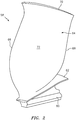
FIG. 2 is a schematic view of a fan blade for use in the gas turbine engine shown inFIG. 1 . -
FIG. 3 is a perspective view of a rotor disk with the fan blade ofFIG. 2 installed. -
FIG. 4 is a sectional view of a coating for the example fan blade ofFIG. 2 . -
FIG. 5 is a process flow chart of an exemplary coating repair process. -
FIG. 1 schematically illustrates agas turbine engine 20. Thegas turbine engine 20 as disclosed herein has a two-spool turbofan that generally incorporates afan section 22, acompressor section 24, acombustor section 26 and aturbine section 28. Thefan section 22 drives air along a bypass flow path while thecompressor section 24 drives air along a core flow path for compression and communication into thecombustor section 26 then expansion through theturbine section 28. Although depicted as a turbofan in the disclosed non-limiting embodiment, it should be appreciated that the concepts described herein are not limited only thereto. - The
engine 20 generally includes alow spool 30 and ahigh spool 32 mounted for rotation around an engine central longitudinal axis A relative to an enginestatic structure 36 viaseveral bearing compartments 38. Thelow spool 30 generally includes aninner shaft 40 that interconnects afan 42, a low pressure compressor 44 ("LPC") and a low pressure turbine 46 ("LPT"). Theinner shaft 40 drives thefan 42 directly or through a gearedarchitecture 48 to drive thefan 42 at a lower speed than thelow spool 30. Thehigh spool 32 includes anouter shaft 50 that interconnects a high pressure compressor 52 ("HPC") and high pressure turbine 54 ("HPT"). Acombustor 56 is arranged between the HPC 52 and the HPT 54. Theinner shaft 40 and theouter shaft 50 are concentric and rotate around the engine central longitudinal axis A which is collinear with their longitudinal axes. - Core airflow is compressed by the
LPC 44 then the HPC 52, mixed with fuel and burned in thecombustor 56, then expanded over the HPT 54 and theLPT 46. Theturbines low spool 30 andhigh spool 32 in response to the expansion. Themain engine shafts bearing compartments 38. It should be appreciated thatvarious bearing compartments 38 at various locations may alternatively or additionally be provided. - Referring also to
Fig. 2 and3 , thefan section 22 includes a plurality of circumferentially spacedfan blades 58 which may be made of a high-strength, low weight material such as an aluminum alloy, titanium alloy, composite material or combinations thereof. It should be understood that although a single fan stage typical of a high bypass gas turbofan engine architecture is illustrated and described in the disclosed embodiments, other stages which have other blades inclusive but not limited to fan blades, high pressure compressor blades and low pressure compressor blades may also benefit from the disclosed process. - Each
fan blade 58 generally includes aninnermost root portion 60, anintermediate platform portion 62, and anoutermost airfoil portion 64. In one form, theroot portion 60 defines an attachment such as an inverted fir tree, bulb, or dovetail, so thefan blade 58 is slidably received in a complimentary configured recess provided in a fan rotor 59 (FIG. 3 ). Theplatform portion 62 generally separates theroot portion 60 and theairfoil portion 64 to define an inner boundary of the air flow path. Theairfoil portion 64 defines a blade chord between a leadingedge 66, which may include various forward and/or aft sweep configurations, and atrailing edge 68. Aconcave pressure side 70 and aconvex suction side 72 are defined between the leadingedge 66 and thetrailing edge 68. Although afan blade 58 is illustrated in the disclosed non-limiting embodiment, compressor blades, turbofan blades, turboprop propeller blades, tilt rotor props, vanes, struts, and other airfoils may benefit from the disclosed process. - With reference to
FIG. 4 , acoating 80 is applied to asubstrate 82 of thefan blade 58. Thecoating 80 generally includes ananodization layer 84 comprising an aluminum oxide, a bond primer orbond primer layer 86, a corrosionresistant primer 88, and anerosion coating 90 coupled in layers. - The
substrate 82, in this embodiment, is thefan blade 58 base metal (e.g., an aluminum alloy). Thecoating 80 protects thesubstrate 82 from corrosion, wear and other physical damage. - The
anodization layer 84, in this embodiment, is defined as an oxide layer formed through a chemical anodization process. The anodization process changes the surface morphology of the aluminum surface and creates an aluminum oxide layer up to 0.0001 inches (0.00254mm) with a microscopic roughness that greatly increases the surface area for bonding and provides for some mechanical retention of bond primers. - The
bond layer 86, in this embodiment, is a corrosion inhibiting organic primer layer (e.g., epoxy-based) which may be spray-applied to a thickness of up to 0.0005 inches (0.0127mm). Thebond layer 86 is applied to increase the bond strength between the underlying aluminum/aluminum oxide 84 and the subsequent primers and coatings by interpenetrating into the micro-roughness of theanodization layer 84 and fully covering any exposed anodize. - The corrosion
resistant primer 88, in this embodiment, is an epoxy-based material and is loaded with hexavalent chromium as the active corrosion-resistant component. Alternatively, the corrosionresistant primer 88 is a non-hexavalent chromium based corrosion-resistant primer. The corrosion-resistant primer 88 is applied to a thickness of approximately 0.001 inches (0.0254mm) to prevent corrosion of the underlying aluminum. The disclosed process can also be utilized for thicker corrosion-resistant primer layers. - The
erosion coating 90, in this embodiment, is an organic erosion coating (e.g., polyurethane) with a thickness of up to 0.030 inches (0.762mm). Theerosion coating 90 protects the underlying primers and metal substrate from damage due to particle and rain impact. - With reference to
FIG. 5 , amethod 100 for repairing or remanufacturing thecoating 80 is schematically disclosed in terms of a functional block diagram flowchart. It should be appreciated that alternative or additional steps may be provided without departing from the teaching herein. The coating 80 (FIG. 4 ) may not be up to specification during manufacture or may be damaged such that remanufacture or repair of thecoating 80 is necessitated. - The
coating 80 to be remanufactured or repaired is initially abraded (102) to leave an abradedsurface 104. In an exemplary embodiment, at least theerosion coating layer 90, most all of the corrosion-resistant primer layer 88, and at least a portion of thebond primer 86 can be removed by an easy/light mechanical removal technique. Some examples of mechanical removal techniques can include mechanical abrasion, plastic media blast, abrasive blast, grinding, sanding, abrasion, laser ablation, waterjet stripping, flashlamp/CO2 stripping, and the like. Abrasive blasting methods can include plastic media, walnut shells, cherry stones, starch, CO2 pellets and the like. Abrasive blasting can deploy harder media, including oxides, carbide or nitrides such as aluminum oxide or silicon carbide. Abrasive blasting can also include fluid jetting techniques including non-abrasive waterjet, liquid nitrogen and the like. The resultant abradedsurface 104 can be relatively rough in texture and be a mixed surface with a combination of material remnants of the abraded layers 84, 86, and 88, as well as bare metal substrate. In other embodiments, portions of thebond primer 86 remain over portions of theanodization layer 84. In exemplary embodiments, a mechanical de-oxidation technique may be required to remove unwanted oxidation on the abradedsurface 104. In exemplary embodiments, after the abrasion and before the application of a sol-gel, the blade can be cleaned with an alkali solution and a scrub brush. The purpose of this cleaning is to remove any remnant plastic media material from the abradedsurface 104. The cleaning at this point in the process also aids the manufacturing process by giving more flexibility with the processing window. It is possible that the alkali wash may have a potential unmeasured effect on one or more of the layers which improves the bonding capability of that layer to the sol-gel. The abradedsurface 104 of the blade can be scrubbed with a soap, alkaline detergent, anionic detergent, cationic detergent, non-ionic detergent or caustic prior to sol-gel application. - At step 106 a sol-gel adhesion promoter is applied to the abraded
surface 104 to form a sol-geladhesion promotion layer 108. The sol-gel adhesion promoter 108 creates a bond to each of the varying surface materials of the abradedsurface 104. Sol-gel processing can include a conversion of monomers into a colloidal solution (sol) that acts as the precursor for an integrated network (or gel) of either discrete particles or network polymers. An exemplary sol-gel can be an AC130-2 or other sol-gel materials that can form similar networked polymers at the abradedsurface 104 utilized in the exemplary method herein. In an exemplary embodiment, the types of adhesion promoting sol-gel materials can be characterized for the properties of adhesion to de-oxidized metal surfaces. The exemplary method utilized herein can employ a sol-gel beneficial to the application to a non-homogenous surface including de-oxidized metal, remnant anodize (aluminum oxide) and remnant organic matrix bond primer. The typical methods of mechanical de-oxidation are not required to accomplish the disclosed method. Sol-gel can be applied by various methods, including wipe applications, immersion techniques and drench shower techniques. In an exemplary embodiment, prior to applying the sol-gel adhesion promoter layer to the abraded surface the following steps can be performed concurrently; abrading the erosion coating; abrading the corrosion-resistant primer; and creating an abraded surface comprising the bond primer over the anodization layer coupled to the substrate. - At step 110 a new corrosion-
resistant primer layer 88 is applied over the sol-geladhesion promotion layer 108. At step 112 a newerosion coating layer 90 is applied over the corrosion-resistant primer layer 88. - The process of repairing erosion coatings for blades and structural guide vanes coated with erosion coatings provides the advantage of replacing damaged erosion coating with the fan blade assembled.
- The process of repairing erosion coatings for blades and structural guide vanes coated with erosion coatings provides the advantage of eliminating several steps commonly used in the repair of an adhesive joint.
- The process makes use of an easy mechanical material removal (plastic media blast) and bonds directly to the created surface utilizing the structure already in place from the original surface preparation steps.
- The process is unlike traditional repairs that remove all of the surface preparation layers and that require the recreation of those surfaces.
- There has been provided a process to repair erosion coatings. While the process to repair erosion coatings has been described in the context of specific embodiments thereof, other unforeseen alternatives, modifications, and variations may become apparent to those skilled in the art having read the foregoing description. Accordingly, it is intended to embrace those alternatives, modifications, and variations which fall within the broad scope of the appended claims.
Claims (13)
- A method of repairing a coating (80) coupled to a substrate (82), wherein the coating (80) comprises an anodization layer (84) on the substrate (82), a bond primer layer (86) on the anodizing layer (84), a corrosion-resistant primer (88) on the bond primer (86), and an erosion coating (90) on the corrosion-resistant primer (86), the method comprising:abrading the erosion coating (90);abrading the corrosion-resistant primer (88);creating an abraded surface (104) comprising said bond primer (86) over said anodization layer (84) coupled to said substrate (82),applying a sol-gel adhesion promoter layer (108) to said abraded surface (104);applying a corrosion-resistant layer (88) over said sol-gel adhesion promoter layer (108); andapplying an erosion coating layer (90) over said corrosion-resistant layer (88).
- The process according to claim 1, wherein said abraded surface (104) comprises at least one of a portion of a bond primer (86) over said anodization layer (84) over said substrate (82) and a portion of a corrosion-resistant primer (88) over a portion of said bond primer (86) over said anodization layer (84) over said substrate (82).
- The process according to claim 1 or 2, wherein said abrading comprises plastic media blast.
- The process according to claim 1, 2 or 3, wherein said abrading step utilizes media selected from the group consisting of plastic media, walnut shells, cherry stones, starch, and CO2 pellets.
- The process according to any preceding claim, wherein said abrading is selected from the group consisting of mechanical abrasion, plastic media blast, abrasive blast, grinding, sanding, laser ablation, waterjet stripping, and flashlamp/CO2 stripping.
- The process according to any preceding claim, wherein said abrading comprises removing said erosion coating (90), removing said corrosion-resistant primer (88), and removing a portion of said bond primer (86).
- The process according to claim 6, wherein said steps of abrading results in creating the abraded surface (104) comprising a non-homogenous combination of any of a bare metal surface, said anodization layer (84), said bond primer (86), and said corrosion-resistant primer (88).
- The process according to claim 7, further comprising:
applying said sol-gel adhesion promoter layer (108) to said abraded surface (104) comprising said non-homogenous combination. - The process according to any preceding claim further comprising:performing a mechanical de-oxidation technique; andremoving oxidation from said abraded surface (104).
- The process according to claim 9, wherein said mechanical de-oxidation technique is performed prior to applying said sol-gel adhesion promoter layer (108).
- The process according to any preceding claim further comprising:prior to said applying said sol-gel adhesion promoter layer (108) to said abraded surface (104);concurrently performing the steps of:abrading the erosion coating (90);abrading the corrosion-resistant primer (88); andcreating an abraded surface (104) comprising said bond primer (86) over said anodization layer (84) coupled to said substrate (82).
- The process according to any preceding claim further comprising:
scrubbing said abraded surface (104) with at least one of a soap, an alkaline detergent, an anionic detergent, a cationic detergent, a non-ionic detergent and a caustic material prior to said sol-gel application. - The process according to any preceding claim wherein said substrate (82) comprises at least a portion of a blade (58) .
Applications Claiming Priority (1)
| Application Number | Priority Date | Filing Date | Title |
|---|---|---|---|
| US15/656,275 US11260421B2 (en) | 2017-07-21 | 2017-07-21 | Method to strip and recoat erosion coatings applied to fan blades and structural guide vanes |
Publications (1)
| Publication Number | Publication Date |
|---|---|
| EP3434865A1 true EP3434865A1 (en) | 2019-01-30 |
Family
ID=63035904
Family Applications (1)
| Application Number | Title | Priority Date | Filing Date |
|---|---|---|---|
| EP18184948.0A Pending EP3434865A1 (en) | 2017-07-21 | 2018-07-23 | Method to strip and recoat erosion coatings applied to fan blades and structural guide vanes |
Country Status (2)
| Country | Link |
|---|---|
| US (1) | US11260421B2 (en) |
| EP (1) | EP3434865A1 (en) |
Cited By (1)
| Publication number | Priority date | Publication date | Assignee | Title |
|---|---|---|---|---|
| EP3564480A1 (en) * | 2018-05-04 | 2019-11-06 | United Technologies Corporation | Method to strip coatings off of an aluminum alloy fan blade |
Families Citing this family (3)
| Publication number | Priority date | Publication date | Assignee | Title |
|---|---|---|---|---|
| US11834964B2 (en) * | 2021-11-24 | 2023-12-05 | General Electric Company | Low radius ratio fan blade for a gas turbine engine |
| US12109585B2 (en) * | 2022-12-01 | 2024-10-08 | Rtx Corporation | Hybrid laser surface processing and spray coating system |
| CN116833895B (en) * | 2023-07-28 | 2026-01-02 | 中国航发动力股份有限公司 | A method for non-destructive removal of the ceramic layer from the metal layer of a guide vane using EB-PVD. |
Citations (5)
| Publication number | Priority date | Publication date | Assignee | Title |
|---|---|---|---|---|
| WO2014150362A1 (en) * | 2013-03-15 | 2014-09-25 | United Technologies Corporation | Blades and manufacture methods |
| WO2015041841A1 (en) * | 2013-09-17 | 2015-03-26 | United Technologies Corporation | Aluminum airfoil with titanium coating |
| EP2987958A2 (en) * | 2014-08-08 | 2016-02-24 | United Technologies Corporation | Aluminum fan blade tip with thermal barrier |
| EP3184180A1 (en) * | 2015-12-24 | 2017-06-28 | United Technologies Corporation | Local repair or remanufacture of polymeric erosion coatings |
| EP3184735A2 (en) * | 2015-12-24 | 2017-06-28 | United Technologies Corporation | Local repair or remanufacture of polymeric erosion coatings |
Family Cites Families (10)
| Publication number | Priority date | Publication date | Assignee | Title |
|---|---|---|---|---|
| US6605365B1 (en) | 1996-11-04 | 2003-08-12 | The Boeing Company | Pigmented alkoxyzirconium sol |
| US5814137A (en) | 1996-11-04 | 1998-09-29 | The Boeing Company | Sol for coating metals |
| US6037060A (en) * | 1996-11-04 | 2000-03-14 | The Boeing Company | Sol for bonding expoxies to aluminum or titanium alloys |
| US6465040B2 (en) | 2001-02-06 | 2002-10-15 | General Electric Company | Method for refurbishing a coating including a thermally grown oxide |
| US20030211330A1 (en) * | 2002-05-09 | 2003-11-13 | Anderson Robert A. | Method of preparing a metal material for bonding |
| US7509735B2 (en) * | 2004-04-22 | 2009-03-31 | Siemens Energy, Inc. | In-frame repairing system of gas turbine components |
| IT1393140B1 (en) * | 2009-03-17 | 2012-04-11 | Nuovo Pignone Spa | METHOD OF PRODUCTION OF A PROTECTIVE COATING FOR A COMPONENT OF A TURBOMACCHINA, THE SAME COMPONENT AND THE RELATED MACHINE |
| DE102010034336B4 (en) | 2010-08-14 | 2013-05-29 | Mtu Aero Engines Gmbh | Method and apparatus for removing a layer from a surface of a body |
| US20120163981A1 (en) * | 2010-12-22 | 2012-06-28 | Hong Shek C | Method and coating for protecting and repairing an airfoil surface |
| WO2014143224A1 (en) | 2013-03-15 | 2014-09-18 | United Technologies Corporation | Turbine engine repair methods |
-
2017
- 2017-07-21 US US15/656,275 patent/US11260421B2/en active Active
-
2018
- 2018-07-23 EP EP18184948.0A patent/EP3434865A1/en active Pending
Patent Citations (5)
| Publication number | Priority date | Publication date | Assignee | Title |
|---|---|---|---|---|
| WO2014150362A1 (en) * | 2013-03-15 | 2014-09-25 | United Technologies Corporation | Blades and manufacture methods |
| WO2015041841A1 (en) * | 2013-09-17 | 2015-03-26 | United Technologies Corporation | Aluminum airfoil with titanium coating |
| EP2987958A2 (en) * | 2014-08-08 | 2016-02-24 | United Technologies Corporation | Aluminum fan blade tip with thermal barrier |
| EP3184180A1 (en) * | 2015-12-24 | 2017-06-28 | United Technologies Corporation | Local repair or remanufacture of polymeric erosion coatings |
| EP3184735A2 (en) * | 2015-12-24 | 2017-06-28 | United Technologies Corporation | Local repair or remanufacture of polymeric erosion coatings |
Cited By (3)
| Publication number | Priority date | Publication date | Assignee | Title |
|---|---|---|---|---|
| EP3564480A1 (en) * | 2018-05-04 | 2019-11-06 | United Technologies Corporation | Method to strip coatings off of an aluminum alloy fan blade |
| US11346371B2 (en) | 2018-05-04 | 2022-05-31 | Raytheon Technologies Corporation | Method to strip coatings off of an aluminum alloy fan blade |
| US11814983B2 (en) | 2018-05-04 | 2023-11-14 | Rtx Corporation | Method to strip coatings off of an aluminum alloy fan blade |
Also Published As
| Publication number | Publication date |
|---|---|
| US20190022698A1 (en) | 2019-01-24 |
| US11260421B2 (en) | 2022-03-01 |
Similar Documents
| Publication | Publication Date | Title |
|---|---|---|
| EP3431712B1 (en) | Method to strip and recoat erosion coatings applied to fan blades and structural guide vanes | |
| EP2540961B1 (en) | Abrasive airfoil tip | |
| EP3434865A1 (en) | Method to strip and recoat erosion coatings applied to fan blades and structural guide vanes | |
| US12025147B2 (en) | Processes and tooling associated with coating application | |
| US20120152893A1 (en) | Method for securing a sheath to a blade | |
| US9926793B2 (en) | Blades and manufacture methods | |
| EP2471607A1 (en) | Turbine component fixture and coating system | |
| US20160186626A1 (en) | Engine component and methods for an engine component | |
| EP3184180B1 (en) | Local repair or remanufacture of polymeric erosion coatings | |
| JP2006097133A (en) | Method of applying turbine wear resistant and environmentally resistant coatings to turbine components | |
| EP2226467B1 (en) | Method of maintaining gas turbine engine components | |
| CN110592520A (en) | Remanufacturing and repairing method for blade boss of aero-engine compressor | |
| CN104582900A (en) | Post processing of components that are laser peened | |
| EP3748125B1 (en) | Methods for repairing a multi-layer coated component of a gas turbine engine | |
| US11926905B2 (en) | Method of removing a ceramic coating from a ceramic coated metallic article | |
| CN113953165A (en) | Spraying process of inorganic aluminum anticorrosive coating of compressor blade disc repair part and compressor blade disc | |
| US12392244B2 (en) | Repair process using plasma etching | |
| US20250361809A1 (en) | Coating system removal method | |
| US20090232975A1 (en) | Method for repairing turbine vanes | |
| Nagy et al. | LPM™ Composite Overlay for Erosion Protection of Turbine Nozzles |
Legal Events
| Date | Code | Title | Description |
|---|---|---|---|
| PUAI | Public reference made under article 153(3) epc to a published international application that has entered the european phase |
Free format text: ORIGINAL CODE: 0009012 |
|
| STAA | Information on the status of an ep patent application or granted ep patent |
Free format text: STATUS: THE APPLICATION HAS BEEN PUBLISHED |
|
| AK | Designated contracting states |
Kind code of ref document: A1 Designated state(s): AL AT BE BG CH CY CZ DE DK EE ES FI FR GB GR HR HU IE IS IT LI LT LU LV MC MK MT NL NO PL PT RO RS SE SI SK SM TR |
|
| AX | Request for extension of the european patent |
Extension state: BA ME |
|
| STAA | Information on the status of an ep patent application or granted ep patent |
Free format text: STATUS: REQUEST FOR EXAMINATION WAS MADE |
|
| 17P | Request for examination filed |
Effective date: 20190730 |
|
| RBV | Designated contracting states (corrected) |
Designated state(s): AL AT BE BG CH CY CZ DE DK EE ES FI FR GB GR HR HU IE IS IT LI LT LU LV MC MK MT NL NO PL PT RO RS SE SI SK SM TR |
|
| RAP1 | Party data changed (applicant data changed or rights of an application transferred) |
Owner name: RAYTHEON TECHNOLOGIES CORPORATION |
|
| STAA | Information on the status of an ep patent application or granted ep patent |
Free format text: STATUS: EXAMINATION IS IN PROGRESS |
|
| 17Q | First examination report despatched |
Effective date: 20220105 |
|
| RAP3 | Party data changed (applicant data changed or rights of an application transferred) |
Owner name: RTX CORPORATION |