EP3434630A1 - Conveying device and storage device - Google Patents
Conveying device and storage device Download PDFInfo
- Publication number
- EP3434630A1 EP3434630A1 EP16895453.5A EP16895453A EP3434630A1 EP 3434630 A1 EP3434630 A1 EP 3434630A1 EP 16895453 A EP16895453 A EP 16895453A EP 3434630 A1 EP3434630 A1 EP 3434630A1
- Authority
- EP
- European Patent Office
- Prior art keywords
- rod
- shaped member
- movable
- movable portion
- bearing
- Prior art date
- Legal status (The legal status is an assumption and is not a legal conclusion. Google has not performed a legal analysis and makes no representation as to the accuracy of the status listed.)
- Granted
Links
Images



Classifications
-
- B—PERFORMING OPERATIONS; TRANSPORTING
- B65—CONVEYING; PACKING; STORING; HANDLING THIN OR FILAMENTARY MATERIAL
- B65G—TRANSPORT OR STORAGE DEVICES, e.g. CONVEYORS FOR LOADING OR TIPPING, SHOP CONVEYOR SYSTEMS OR PNEUMATIC TUBE CONVEYORS
- B65G54/00—Non-mechanical conveyors not otherwise provided for
- B65G54/02—Non-mechanical conveyors not otherwise provided for electrostatic, electric, or magnetic
- B65G54/025—Non-mechanical conveyors not otherwise provided for electrostatic, electric, or magnetic the load being magnetically coupled with a piston-like driver moved within a tube
-
- B—PERFORMING OPERATIONS; TRANSPORTING
- B65—CONVEYING; PACKING; STORING; HANDLING THIN OR FILAMENTARY MATERIAL
- B65G—TRANSPORT OR STORAGE DEVICES, e.g. CONVEYORS FOR LOADING OR TIPPING, SHOP CONVEYOR SYSTEMS OR PNEUMATIC TUBE CONVEYORS
- B65G25/00—Conveyors comprising a cyclically-moving, e.g. reciprocating, carrier or impeller which is disengaged from the load during the return part of its movement
- B65G25/04—Conveyors comprising a cyclically-moving, e.g. reciprocating, carrier or impeller which is disengaged from the load during the return part of its movement the carrier or impeller having identical forward and return paths of movement, e.g. reciprocating conveyors
-
- B—PERFORMING OPERATIONS; TRANSPORTING
- B65—CONVEYING; PACKING; STORING; HANDLING THIN OR FILAMENTARY MATERIAL
- B65G—TRANSPORT OR STORAGE DEVICES, e.g. CONVEYORS FOR LOADING OR TIPPING, SHOP CONVEYOR SYSTEMS OR PNEUMATIC TUBE CONVEYORS
- B65G1/00—Storing articles, individually or in orderly arrangement, in warehouses or magazines
- B65G1/02—Storage devices
- B65G1/04—Storage devices mechanical
-
- F—MECHANICAL ENGINEERING; LIGHTING; HEATING; WEAPONS; BLASTING
- F16—ENGINEERING ELEMENTS AND UNITS; GENERAL MEASURES FOR PRODUCING AND MAINTAINING EFFECTIVE FUNCTIONING OF MACHINES OR INSTALLATIONS; THERMAL INSULATION IN GENERAL
- F16H—GEARING
- F16H25/00—Gearings comprising primarily only cams, cam-followers and screw-and-nut mechanisms
- F16H25/18—Gearings comprising primarily only cams, cam-followers and screw-and-nut mechanisms for conveying or interconverting oscillating or reciprocating motions
- F16H25/20—Screw mechanisms
- F16H25/24—Elements essential to such mechanisms, e.g. screws, nuts
-
- F—MECHANICAL ENGINEERING; LIGHTING; HEATING; WEAPONS; BLASTING
- F16—ENGINEERING ELEMENTS AND UNITS; GENERAL MEASURES FOR PRODUCING AND MAINTAINING EFFECTIVE FUNCTIONING OF MACHINES OR INSTALLATIONS; THERMAL INSULATION IN GENERAL
- F16H—GEARING
- F16H49/00—Other gearings
-
- H—ELECTRICITY
- H02—GENERATION; CONVERSION OR DISTRIBUTION OF ELECTRIC POWER
- H02K—DYNAMO-ELECTRIC MACHINES
- H02K49/00—Dynamo-electric clutches; Dynamo-electric brakes
- H02K49/10—Dynamo-electric clutches; Dynamo-electric brakes of the permanent-magnet type
- H02K49/102—Magnetic gearings, i.e. assembly of gears, linear or rotary, by which motion is magnetically transferred without physical contact
-
- H—ELECTRICITY
- H02—GENERATION; CONVERSION OR DISTRIBUTION OF ELECTRIC POWER
- H02K—DYNAMO-ELECTRIC MACHINES
- H02K7/00—Arrangements for handling mechanical energy structurally associated with dynamo-electric machines, e.g. structural association with mechanical driving motors or auxiliary dynamo-electric machines
- H02K7/06—Means for converting reciprocating motion into rotary motion or vice versa
-
- F—MECHANICAL ENGINEERING; LIGHTING; HEATING; WEAPONS; BLASTING
- F16—ENGINEERING ELEMENTS AND UNITS; GENERAL MEASURES FOR PRODUCING AND MAINTAINING EFFECTIVE FUNCTIONING OF MACHINES OR INSTALLATIONS; THERMAL INSULATION IN GENERAL
- F16H—GEARING
- F16H25/00—Gearings comprising primarily only cams, cam-followers and screw-and-nut mechanisms
- F16H25/18—Gearings comprising primarily only cams, cam-followers and screw-and-nut mechanisms for conveying or interconverting oscillating or reciprocating motions
- F16H25/20—Screw mechanisms
- F16H25/24—Elements essential to such mechanisms, e.g. screws, nuts
- F16H2025/249—Materials or coatings for screws or nuts
Definitions
- the present invention relates to a transfer technique, more particularly, to a transfer apparatus and a storage apparatus.
- a male screw made of a magnetic material is rotated to move a female screw such as a nut made of a magnetic material in a direction of a central axis of the male screw.
- a load of the male screw is normally received by fixed bearings disposed at both ends.
- the male screw may be subjected to flexure when the load of the male screw is received only by the fixed bearings disposed at both ends of the male screw. Therefore, in order to prevent or reduce the flexure of the male screw, a movable bearing configured to be movable may be provided between the fixed bearings in a manner not hindering a movement of the female screw (for example, see PTLs 1 to 3).
- a movable bearing of the related art may have a power mechanism provided with a motor or the like for moving the movable bearing separately from a driving device configured to rotate a male screw.
- the power mechanism may be connected to the movable bearing.
- the power mechanism may generate heat or dust.
- the movable bearing of a transfer apparatus may be installed at a place where generation of heat and dust is preferably reduced or prevented such as a temperature-controlled furnace. In this case, if the movable bearing cannot be separated from the power mechanism, heat or dust may be generated in the periphery of the movable bearing, that is, in the temperature-controlled furnace.
- the movable bearing that cannot be decoupled from the power mechanism may not be installed. Accordingly, it is one of objects of the present invention to provide a transfer apparatus and a storage apparatus configured to allow decoupling of a movable bearing from a power source of the movable bearing.
- a transfer apparatus including:
- the movable portion may include a magnet configured to couple the movable portion to the movable bearing.
- the movable bearing is provided with a magnet configured to couple the movable bearing to the movable portion.
- the decoupling mechanism may hinder the movement of the movable bearing pulled by the movable portion.
- the decoupling mechanism may be configured to make contact with the movable bearing and hinder the movement of the movable bearing pulled by the movable portion.
- the transfer apparatus described above may further include a fixed bearing configured to receive a load of the rod-shaped member at an end portion of the rod-shaped member.
- a storage apparatus including:
- the movable portion may include a magnet configured to couple the movable portion to the movable bearing.
- the movable bearing is provided with a magnet configured to couple the movable bearing to the movable portion.
- the movable bearing may be movable in an interior of the storage warehouse.
- the decoupling mechanism may hinder the movement of the movable bearing pulled by the movable portion.
- the decoupling mechanism may be configured to make contact with the movable bearing and hinder the movement of the movable bearing pulled by the movable portion.
- the decoupling mechanism may prevent the movable bearing pulled by the movable portion from coming out from the storage warehouse.
- the storage apparatus described above may further include a fixed bearing configured to receive a load of the rod-shaped member at an end portion of the rod-shaped member.
- the driving device may be disposed outside the storage warehouse.
- the storage warehouse may be a temperature-controlled furnace having a temperature-controlled space.
- a transfer apparatus and a storage apparatus configured to allow decoupling of a movable bearing and a power source of the movable bearing may be provided.
- the storage apparatus includes a storage warehouse 1 that stores articles and a transfer apparatus 15 that transfers the articles, as illustrated in Fig. 1 .
- the storage warehouse 1 is, for example, a temperature-controlled furnace having a temperature-controlled space that houses the articles.
- the temperature-controlled furnace is, for example, a freeze drying furnace.
- a shelf board is disposed horizontally in the storage warehouse 1 and the articles including an object to be freeze-dried are disposed on the shelf board.
- the articles are, for example, vials containing a medicine poured therein.
- the transfer apparatus 15 includes a first rod-shaped member 2A including a magnetic material, a second rod-shaped member 2B including a magnetic material, a driving device 4 configured to rotate the first and second rod-shaped members 2A and 2B about central axes of the first and second rod-shaped members 2A and 2B, and a movable portion 33 facing parts of side surfaces of the first and second rod-shaped members 2A and 2B and including a magnetic material, the movable portion 33 moving along the central axes of the first and second rod-shaped members 2A and 2B when the driving device 4 rotates the first and second rod-shaped members 2A and 2B.
- the transfer apparatus 15 may be coupled to and decoupled from the movable portion 33 by a magnetic force and may include a movable bearing 35 capable of moving along the central axis of the first rod-shaped member 2A in association with the movement of the movable portion 33 upon reception of a radial load of the first rod-shaped member 2A for example, and a decoupling mechanism 37 configured to decouple the movable bearing 35 coupled to the movable portion 33 by the magnetic force from the movable portion 33.
- the first rod-shaped member 2A is disposed in an interior of the storage warehouse 1.
- the second rod-shaped member 2B is disposed in a space outside the storage warehouse 1.
- an outer diameter of the first rod-shaped member 2A is identical to an outer diameter of the second rod-shaped member 2B.
- the first rod-shaped member 2A and the second rod-shaped member 2B are disposed so that a central axis of the first rod-shaped member 2A and a central axis of the second rod-shaped member 2B are aligned on an identical line.
- the first rod-shaped member 2A is covered with a first cover 20A. A first end portion of the first rod-shaped member 2A is inserted into a first terminal member 22A. A second end portion of the first rod-shaped member 2A is inserted into a second terminal member 23A.
- the second rod-shaped member 2B is covered with a second cover 20B. A first end portion of the second rod-shaped member 2B is inserted into a third terminal member 22B. A second end portion of the second rod-shaped member 2B is inserted into a fourth terminal member 23B.
- the second terminal member 23A and the third terminal member 22B are connected via a connection member 70.
- the second terminal member 23A and the third terminal member 22B may be decoupled.
- a driving device 4 is coupled to the second rod-shaped member 2B via a mandrel portion of the fourth terminal member 23B.
- the driving device 4 and the fourth terminal member 23B may be coupled via a coupling device (coupling) 14, for example.
- the driving device 4 includes, for example, a rotating motor, and is disposed outside a temperature-controlled space in the storage warehouse 1.
- the driving device 4 may be covered with a shield or the like which prevents diffusion of possible dust or the like.
- the driving device 4 causes the fourth terminal member 23B to rotate about the central axes of the first and second rod-shaped members 2A and 2B as an axis of rotation
- the second rod-shaped member 2B, the third terminal member 22B, the second terminal member 23A, the first rod-shaped member 2A, and the first terminal member 22A illustrated in Fig. 2 rotate simultaneously.
- the first rod-shaped member 2A is a magnetic screw including a magnetic material and an outer peripheral surface thereof is threaded in a spiral shape.
- the first cover 20A is, for example, a thin-walled pipe of a nonmagnetic material made of stainless steel, aluminum, resin, or the like.
- the first rod-shaped member 2A is inserted into the first cover 20A having a cylindrical shape.
- the central axis of the first rod-shaped member 2A is aligned with the central axis of the first cover 20A.
- the first cover 20A also rotates about the central axis of the first rod-shaped member 2A.
- the second rod-shaped member 2B is also a magnetic screw including a magnetic material and the outer peripheral surface thereof is threaded in a spiral shape.
- the second cover 20B is, for example, a thin-walled pipe of a nonmagnetic material made of stainless steel, aluminum, resin, or the like.
- the second rod-shaped member 2B is inserted into the second cover 20B having a cylindrical shape.
- the central axis of the second rod-shaped member 2B is aligned with the central axis of the second cover 20B.
- the second cover 20B also rotates about the central axis of the second rod-shaped member 2B.
- the transfer apparatus 15 further includes a first fixed bearing 12 configured to receive a load from the first rod-shaped member 2A via a mandrel portion of the first terminal member 22A, and a second fixed bearing 13 configured to receive a load from the second rod-shaped member 2B via the mandrel portion of the fourth terminal member 23B as illustrated in Fig. 1 and Fig. 2 .
- the first fixed bearing 12 is disposed, for example, in the storage warehouse 1.
- the second fixed bearing 13 is disposed, for example, outside the storage warehouse 1.
- the movable portion 33 further includes an opposite member 3 that faces part of the side surfaces of the first and second rod-shaped members 2A and 2B and including a magnetic material as illustrated in Fig. 1 .
- the opposite member 3 is a magnetic nut including a magnetic material and provided with a hole having an inner circumference larger than outer circumferences of the first and second rod-shaped members 2A and 2B.
- the first and second rod-shaped members 2A and 2B penetrate through a hole in the opposite member 3 having a nut shape.
- S pole magnetized zones and N pole magnetized zones are alternately provided in a spiral shape on an inner peripheral surface of the hole in the opposite member 3.
- a pitch of the magnetized zones of the opposite member 3 is substantially the same as a pitch of the threads of the first and second rod-shaped members 2A and 2B.
- Guide rings 31 and 32 such as bushes may be provided on an inner peripheral surface of the opposite member 3.
- the inner circumferences of the respective guide rings 31 and 32 are smaller than the inner circumference of the opposite member 3 and make contact with the outer peripheral surfaces of the first and second covers 20A and 20B. Therefore, a constant interval is kept between the threads of the first and second rod-shaped members 2A and 2B and the magnetized zones of the opposite member 3.
- the guide rings 31 and 32 are made of a material having a small friction coefficient, such as fluororesin.
- a magnetic force acts between the threads of the first and second rod-shaped members 2A and 2B illustrated in Fig. 1 and the magnetized zone of the opposite member 3.
- the opposite member 3 is fixed to the movable portion 33 in a non-rotatable manner. Therefore, when the driving device 4 rotates the first and second rod-shaped members 2A and 2B, the movable portion 33 provided with the opposite member 3 moves linearly along the central axes of the first and second rod-shaped members 2A and 2B. A direction of travel of the movable portion 33 is switched depending on the direction of rotation of the first and second rod-shaped members 2A and 2B. Therefore, the movable portion 33 may reciprocate along the central axes of the first and second rod-shaped members 2A and 2B.
- the movable portion 33 may be provided with wheels or the like configured to rotate in contact with a floor or a rail on the floor.
- the movable portion 33 may also be supported by, for example, a guide rail.
- the movable portion 33 is provided, for example, with a table for placing articles.
- first rod-shaped member 2A and the second rod-shaped member 2B are connected in such a manner that a screw pitch of an extended screw shaft matches the screw pitch of the second rod-shaped member 2B and does not cause any misalignment even when the screw shaft of the first rod-shaped member 2A is extended. Accordingly, the opposite member 3 is allowed to move smoothly from the first rod-shaped member 2A to the second rod-shaped member 2B, or from the second rod-shaped member 2B to the first rod-shaped member 2A at a connecting portion between the first rod-shaped member 2A and the second rod-shaped member 2B.
- the movable bearing 35 is movable, for example, in the interior of the storage warehouse 1. As illustrated in Fig. 4 , the movable bearing 35 is provided with a through-hole 45 configured to allow the first rod-shaped member 2A and the first cover 20A to pass through. An inner wall of the through-hole 45 provided in the movable bearing 35 is not provided with a magnetic material. Therefore, even when the first rod-shaped member 2A illustrated in Fig. 1 rotates, the movable bearing 35 does not move solely. The movable bearing 35 moves by being pushed by the movable portion 33 or by being pulled by the movable portion 33 coupled by a magnetic force.
- the movable bearing 35 may be provided with wheels or the like configured to rotate in contact with a floor or a rail on the floor.
- a magnet 135 is provided on a surface of the movable bearing 35 facing the movable portion 33.
- a magnet 133 is provided on a surface of the movable portion 33 facing the movable bearing 35.
- a configuration in which the magnet 135 may be provided on the movable bearing 35 and a member including iron to be coupled to the magnet 135 is provided on the surface of the movable portion 33 facing the movable bearing 35 is also applicable.
- a configuration in which the magnet 133 may be provided on the movable portion 33 and a member including iron to be coupled to the magnet 133 is provided on the surface of the movable bearing 35 facing the movable portion 33 is also applicable.
- the movable bearing 35 is pulled by the movable portion 33 by a magnetic force and moves along the first rod-shaped member 2A as illustrated in Fig. 6(a) .
- the decoupling mechanism 37 being, for example, a hook shaped column
- a movement of the movable bearing 35 in a direction in which the movable bearing 35 is pulled by the movable portion 33 is stopped by the decoupling mechanism 37 as illustrated in Fig. 6(b) and Fig. 6(c) .
- the movable bearing 35 coupled by a magnetic force is decoupled from the movable portion 33. Accordingly, the movable bearing 35 pulled by the movable portion 33 is prevented from coming out from the storage warehouse.
- the driving torque is transmitted between the first and second rod-shaped members 2A and 2B and the opposite member 3 illustrated in Fig. 1 in a non-contact manner by a magnetic force. Therefore, when a driving torque is transmitted between the first and second rod-shaped members 2A and 2B and the opposite member 3, heat and dust are unlikely to be generated. Accordingly, even if the opposite member 3 moves in the temperature-controlled space in the storage warehouse 1, an influence of heat generation in the temperature-controlled space may be prevented or reduced and the temperature-controlled space may be kept clean.
- the driving device 4 since the driving device 4 is disposed outside the temperature-controlled space in the storage warehouse 1, even if dust is generated in the driving device 4, the dust is unlikely to enter the temperature-controlled space in the storage warehouse 1. If the driving devices are disposed in the interior of the temperature-controlled furnace, the temperature distribution may become uneven in the temperature-controlled furnace such as a freeze drying furnace due to the heated driving devices. In this case, the quality of multiple articles disposed in the temperature-controlled furnace may become uneven. In contrast, in the storage apparatus according to the embodiment, since the driving device 4 is disposed outside the temperature-controlled space in the storage warehouse 1, the temperature is unlikely to become uneven in the storage warehouse 1.
- the movable bearing 35 since the movement of the movable bearing 35 is performed via the movable portion 33, the movable bearing 35 is separated from the driving device 4, which is a power source. Therefore, even though the driving device 4 is disposed outside the storage warehouse 1, the movable bearing 35 may be moved in the interior of the storage warehouse 1. In addition, since the movement of the movable bearing 35 is performed via the movable portion 33, a door of the storage warehouse 1 may be opened and closed by separating the connecting portion between the first rod-shaped member 2A and the second rod-shaped member 2B located near the door.
- the movable bearing 35 may preferably stay in the storage warehouse 1. Limiting of movable range of the movable bearing 35, not only in the storage warehouse 1, may be preferred depending on the case. In contrast, according to the storage apparatus of the embodiment, the movable range of the movable bearing 35 may be set within a range smaller than the movable range of the movable portion 33 by the decoupling mechanism 37.
- Fig. 3 illustrates the first rod-shaped member 2A provided with the threads.
- the outer peripheral surface of the first rod-shaped member 2A may be provided with S pole magnetized zones and N pole magnetized zones alternately in a spiral shape.
- the pitch of the magnetized zones of the first rod-shaped member 2A illustrated in Fig. 7 is substantially identical to the pitch of the magnetized zones of the opposite member 3.
- the opposite member 3 may be a threaded magnetic material.
- the surface of a threaded hole in the opposite member 3 may be covered with a thin-walled pipe 30 formed of a nonmagnetic material. This can prevent foreign matters from adhering to a threaded groove of the opposite member 3.
- the structure of the first rod-shaped member 2A is the same as that of Fig. 7 .
- the pitch of the threads of the opposite member 3 illustrated in Fig. 8 is substantially the same as the pitch of the magnetized zones of the first rod-shaped member 2A.
- the shape of the opposite member is not limited to the nut shape, but may be, for example, a concave shape.
- the rod-shaped member passes through the concave portion of the concave opposite member.
- S pole magnetized zones and N pole magnetized zones are alternately provided on the side surface of the concave portion of the concave opposite member.
- the storage warehouse may be a sterilization processing furnace or a fermenting furnace or may be a storage warehouse that does not undergo temperature control.
- the articles transferred to the inside and the outside of the storage warehouse are not limited to medicines, but may include foods, beverages, precision parts, etc., as well as any articles.
- the transfer apparatus is not necessarily combined with the storage warehouse. As described above, it should be understood that the invention encompasses various embodiments and the like not described in the specification.
Landscapes
- Engineering & Computer Science (AREA)
- General Engineering & Computer Science (AREA)
- Mechanical Engineering (AREA)
- Power Engineering (AREA)
- Warehouses Or Storage Devices (AREA)
- Non-Mechanical Conveyors (AREA)
- Magnetic Bearings And Hydrostatic Bearings (AREA)
Abstract
Description
- The present invention relates to a transfer technique, more particularly, to a transfer apparatus and a storage apparatus.
- In a transfer apparatus using a magnetic screw, a male screw made of a magnetic material is rotated to move a female screw such as a nut made of a magnetic material in a direction of a central axis of the male screw. A load of the male screw is normally received by fixed bearings disposed at both ends. However, if the male screw is long, the male screw may be subjected to flexure when the load of the male screw is received only by the fixed bearings disposed at both ends of the male screw. Therefore, in order to prevent or reduce the flexure of the male screw, a movable bearing configured to be movable may be provided between the fixed bearings in a manner not hindering a movement of the female screw (for example, see
PTLs 1 to 3). -
- PTL 1:
JP-A-58-109242 - PTL 2: Japanese Patent No.
2867386 - PTL 3: Japanese Patent No.
2923951 - A movable bearing of the related art may have a power mechanism provided with a motor or the like for moving the movable bearing separately from a driving device configured to rotate a male screw. The power mechanism may be connected to the movable bearing. However, the power mechanism may generate heat or dust. In contrast, the movable bearing of a transfer apparatus may be installed at a place where generation of heat and dust is preferably reduced or prevented such as a temperature-controlled furnace. In this case, if the movable bearing cannot be separated from the power mechanism, heat or dust may be generated in the periphery of the movable bearing, that is, in the temperature-controlled furnace. Depending on the limitation of the availability of an installation space, the movable bearing that cannot be decoupled from the power mechanism may not be installed. Accordingly, it is one of objects of the present invention to provide a transfer apparatus and a storage apparatus configured to allow decoupling of a movable bearing from a power source of the movable bearing.
- According to an aspect of the present invention, there is provided a transfer apparatus including:
- (a) a rod-shaped member including a magnetic material;
- (b) a driving device configured to rotate the rod-shaped member about a central axis of the rod-shaped member;
- (c) a movable portion facing part of a side surface of the rod-shaped member, the movable portion including a magnetic material and being configured to move along the central axis of the rod-shaped member when the driving device rotates the rod-shaped member;
- (d) a movable bearing capable of being coupled to the movable portion by a magnetic force, the movable bearing receiving a load from the rod-shaped member and movable along the central axis of the rod-shaped member in association with the movement of the movable portion; and
- (e) a decoupling mechanism configured to decouple the movable bearing coupled by the magnetic force from the movable portion.
- In the transfer apparatus described above, the movable portion may include a magnet configured to couple the movable portion to the movable bearing. The movable bearing is provided with a magnet configured to couple the movable bearing to the movable portion.
- In the transfer apparatus described above, the decoupling mechanism may hinder the movement of the movable bearing pulled by the movable portion. The decoupling mechanism may be configured to make contact with the movable bearing and hinder the movement of the movable bearing pulled by the movable portion.
- The transfer apparatus described above may further include a fixed bearing configured to receive a load of the rod-shaped member at an end portion of the rod-shaped member.
- According to an aspect of the present invention, there is provided a storage apparatus including:
- (a) warehouse configured to store an article;
- (b) a rod-shaped member including a magnetic material, at least part of the rod-shaped member being positioned in the interior of the warehouse;
- (c) a driving device configured to rotate the rod-shaped member about a central axis of the rod-shaped member;
- (d) a movable portion facing part of a side surface of the rod-shaped member, the movable portion including a magnetic material and being configured to move along the central axis of the rod-shaped member to move an article when the driving device rotates the rod-shaped member;
- (e) a movable bearing capable of being coupled to the movable portion by a magnetic force, the movable bearing receiving a load from the rod-shaped member and movable along the central axis of the rod-shaped member in association with the movement of the movable portion; and
- (f) a decoupling mechanism configured to decouple the movable bearing coupled by the magnetic force from the movable portion.
- In the storage apparatus described above, the movable portion may include a magnet configured to couple the movable portion to the movable bearing. The movable bearing is provided with a magnet configured to couple the movable bearing to the movable portion.
- In the storage apparatus described above, the movable bearing may be movable in an interior of the storage warehouse.
- In the storage apparatus described above, the decoupling mechanism may hinder the movement of the movable bearing pulled by the movable portion. The decoupling mechanism may be configured to make contact with the movable bearing and hinder the movement of the movable bearing pulled by the movable portion. The decoupling mechanism may prevent the movable bearing pulled by the movable portion from coming out from the storage warehouse.
- The storage apparatus described above may further include a fixed bearing configured to receive a load of the rod-shaped member at an end portion of the rod-shaped member.
- In the storage apparatus described above, the driving device may be disposed outside the storage warehouse.
- In the storage apparatus described above, the storage warehouse may be a temperature-controlled furnace having a temperature-controlled space.
- According to the present invention, a transfer apparatus and a storage apparatus configured to allow decoupling of a movable bearing and a power source of the movable bearing may be provided.
-
-
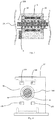
Fig. 1 is a schematic cross-sectional view illustrating a storage apparatus according to an embodiment of the invention. -
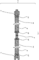
Fig. 2 is a schematic cross-sectional view illustrating a transfer apparatus according to the embodiment of the invention. -
Fig. 3 is a schematic cross-sectional view illustrating a first rod-shaped member and an opposite member according to the embodiment of the invention. -
Fig. 4 is a schematic front view illustrating a movable bearing and a decoupling mechanism according to the embodiment of the invention. -
Fig. 5 is conceptual drawings illustrating an action of the transfer apparatus according to the embodiment of the invention. -
Fig. 6 is conceptual drawings illustrating an action of the transfer apparatus according to the embodiment of the invention. -
Fig. 7 is a schematic view illustrating a first rod-shaped member and an opposite member according to a modification of the embodiment of the invention. -
Fig. 8 is a schematic view illustrating the first rod-shaped member and the opposite member according to the modification of the embodiment of the invention. - Embodiments of the present invention will be described below. In the description of the drawings given below, the same or similar parts are denoted by the same or similar reference numerals. However, the drawings are schematically illustrated. Therefore, specific dimensions and the like should be determined with reference to the following description. It will be appreciated that the relationship or ratio between dimensions may be different among the drawings.
- The storage apparatus according to the embodiment of the present invention includes a
storage warehouse 1 that stores articles and atransfer apparatus 15 that transfers the articles, as illustrated inFig. 1 . Thestorage warehouse 1 is, for example, a temperature-controlled furnace having a temperature-controlled space that houses the articles. The temperature-controlled furnace is, for example, a freeze drying furnace. For example, a shelf board is disposed horizontally in thestorage warehouse 1 and the articles including an object to be freeze-dried are disposed on the shelf board. The articles are, for example, vials containing a medicine poured therein. - The
transfer apparatus 15 includes a first rod-shapedmember 2A including a magnetic material, a second rod-shapedmember 2B including a magnetic material, adriving device 4 configured to rotate the first and second rod-shapedmembers members movable portion 33 facing parts of side surfaces of the first and second rod-shapedmembers movable portion 33 moving along the central axes of the first and second rod-shapedmembers driving device 4 rotates the first and second rod-shapedmembers - The
transfer apparatus 15 may be coupled to and decoupled from themovable portion 33 by a magnetic force and may include amovable bearing 35 capable of moving along the central axis of the first rod-shapedmember 2A in association with the movement of themovable portion 33 upon reception of a radial load of the first rod-shapedmember 2A for example, and adecoupling mechanism 37 configured to decouple themovable bearing 35 coupled to themovable portion 33 by the magnetic force from themovable portion 33. - For example, the first rod-shaped
member 2A is disposed in an interior of thestorage warehouse 1. The second rod-shapedmember 2B is disposed in a space outside thestorage warehouse 1. As illustrated inFig. 2 , an outer diameter of the first rod-shapedmember 2A is identical to an outer diameter of the second rod-shapedmember 2B. The first rod-shapedmember 2A and the second rod-shapedmember 2B are disposed so that a central axis of the first rod-shapedmember 2A and a central axis of the second rod-shapedmember 2B are aligned on an identical line. - The first rod-shaped
member 2A is covered with afirst cover 20A. A first end portion of the first rod-shapedmember 2A is inserted into afirst terminal member 22A. A second end portion of the first rod-shapedmember 2A is inserted into asecond terminal member 23A. - The second rod-shaped
member 2B is covered with asecond cover 20B. A first end portion of the second rod-shapedmember 2B is inserted into athird terminal member 22B. A second end portion of the second rod-shapedmember 2B is inserted into afourth terminal member 23B. - The
second terminal member 23A and thethird terminal member 22B are connected via aconnection member 70. When a door of thestorage warehouse 1 illustrated inFig. 1 is closed, thesecond terminal member 23A and thethird terminal member 22B may be decoupled. - As illustrated in
Fig. 1 , adriving device 4 is coupled to the second rod-shapedmember 2B via a mandrel portion of thefourth terminal member 23B. The drivingdevice 4 and thefourth terminal member 23B may be coupled via a coupling device (coupling) 14, for example. The drivingdevice 4 includes, for example, a rotating motor, and is disposed outside a temperature-controlled space in thestorage warehouse 1. The drivingdevice 4 may be covered with a shield or the like which prevents diffusion of possible dust or the like. - When the
driving device 4 causes thefourth terminal member 23B to rotate about the central axes of the first and second rod-shapedmembers member 2B, thethird terminal member 22B, thesecond terminal member 23A, the first rod-shapedmember 2A, and thefirst terminal member 22A illustrated inFig. 2 rotate simultaneously. - As illustrated in
Fig. 3 , the first rod-shapedmember 2A is a magnetic screw including a magnetic material and an outer peripheral surface thereof is threaded in a spiral shape. Thefirst cover 20A is, for example, a thin-walled pipe of a nonmagnetic material made of stainless steel, aluminum, resin, or the like. The first rod-shapedmember 2A is inserted into thefirst cover 20A having a cylindrical shape. The central axis of the first rod-shapedmember 2A is aligned with the central axis of thefirst cover 20A. When the first rod-shapedmember 2A rotates, thefirst cover 20A also rotates about the central axis of the first rod-shapedmember 2A. - As illustrated in
Fig. 1 , the second rod-shapedmember 2B is also a magnetic screw including a magnetic material and the outer peripheral surface thereof is threaded in a spiral shape. Thesecond cover 20B is, for example, a thin-walled pipe of a nonmagnetic material made of stainless steel, aluminum, resin, or the like. The second rod-shapedmember 2B is inserted into thesecond cover 20B having a cylindrical shape. The central axis of the second rod-shapedmember 2B is aligned with the central axis of thesecond cover 20B. When the second rod-shapedmember 2B rotates, thesecond cover 20B also rotates about the central axis of the second rod-shapedmember 2B. - The
transfer apparatus 15 further includes a first fixedbearing 12 configured to receive a load from the first rod-shapedmember 2A via a mandrel portion of thefirst terminal member 22A, and a second fixed bearing 13 configured to receive a load from the second rod-shapedmember 2B via the mandrel portion of thefourth terminal member 23B as illustrated inFig. 1 andFig. 2 . The first fixedbearing 12 is disposed, for example, in thestorage warehouse 1. The second fixedbearing 13 is disposed, for example, outside thestorage warehouse 1. - The
movable portion 33 further includes anopposite member 3 that faces part of the side surfaces of the first and second rod-shapedmembers Fig. 1 . Theopposite member 3 is a magnetic nut including a magnetic material and provided with a hole having an inner circumference larger than outer circumferences of the first and second rod-shapedmembers members opposite member 3 having a nut shape. - As illustrated in
Fig. 3 , S pole magnetized zones and N pole magnetized zones are alternately provided in a spiral shape on an inner peripheral surface of the hole in theopposite member 3. A pitch of the magnetized zones of theopposite member 3 is substantially the same as a pitch of the threads of the first and second rod-shapedmembers opposite member 3. The inner circumferences of the respective guide rings 31 and 32 are smaller than the inner circumference of theopposite member 3 and make contact with the outer peripheral surfaces of the first andsecond covers members opposite member 3. The guide rings 31 and 32 are made of a material having a small friction coefficient, such as fluororesin. - A magnetic force acts between the threads of the first and second rod-shaped
members Fig. 1 and the magnetized zone of theopposite member 3. Theopposite member 3 is fixed to themovable portion 33 in a non-rotatable manner. Therefore, when thedriving device 4 rotates the first and second rod-shapedmembers movable portion 33 provided with theopposite member 3 moves linearly along the central axes of the first and second rod-shapedmembers movable portion 33 is switched depending on the direction of rotation of the first and second rod-shapedmembers movable portion 33 may reciprocate along the central axes of the first and second rod-shapedmembers movable portion 33 may be provided with wheels or the like configured to rotate in contact with a floor or a rail on the floor. Themovable portion 33 may also be supported by, for example, a guide rail. Themovable portion 33 is provided, for example, with a table for placing articles. - Note that the first rod-shaped
member 2A and the second rod-shapedmember 2B are connected in such a manner that a screw pitch of an extended screw shaft matches the screw pitch of the second rod-shapedmember 2B and does not cause any misalignment even when the screw shaft of the first rod-shapedmember 2A is extended. Accordingly, theopposite member 3 is allowed to move smoothly from the first rod-shapedmember 2A to the second rod-shapedmember 2B, or from the second rod-shapedmember 2B to the first rod-shapedmember 2A at a connecting portion between the first rod-shapedmember 2A and the second rod-shapedmember 2B. - The
movable bearing 35 is movable, for example, in the interior of thestorage warehouse 1. As illustrated inFig. 4 , themovable bearing 35 is provided with a through-hole 45 configured to allow the first rod-shapedmember 2A and thefirst cover 20A to pass through. An inner wall of the through-hole 45 provided in themovable bearing 35 is not provided with a magnetic material. Therefore, even when the first rod-shapedmember 2A illustrated inFig. 1 rotates, themovable bearing 35 does not move solely. Themovable bearing 35 moves by being pushed by themovable portion 33 or by being pulled by themovable portion 33 coupled by a magnetic force. Themovable bearing 35 may be provided with wheels or the like configured to rotate in contact with a floor or a rail on the floor. - A
magnet 135 is provided on a surface of themovable bearing 35 facing themovable portion 33. Amagnet 133 is provided on a surface of themovable portion 33 facing themovable bearing 35. A configuration in which themagnet 135 may be provided on themovable bearing 35 and a member including iron to be coupled to themagnet 135 is provided on the surface of themovable portion 33 facing themovable bearing 35 is also applicable. Alternatively, a configuration in which themagnet 133 may be provided on themovable portion 33 and a member including iron to be coupled to themagnet 133 is provided on the surface of themovable bearing 35 facing themovable portion 33 is also applicable. - As illustrated in
Fig. 5(a) , when themovable portion 33 approaches themovable bearing 35 by the drivingdevice 4 rotating the first and second rod-shapedmembers magnet 133 of themovable portion 33 and themagnet 135 of themovable bearing 35 are coupled as illustrated inFig. 5(b) . Themovable bearing 35 coupled to themovable portion 33 by a magnetic force is pushed by themovable portion 33 and moves along the first rod-shapedmember 2A as illustrated inFig. 5(c) . - When the
driving device 4 rotates the first and second rod-shapedmembers Fig. 5 , themovable bearing 35 is pulled by themovable portion 33 by a magnetic force and moves along the first rod-shapedmember 2A as illustrated inFig. 6(a) . As illustrated inFig. 4 , when themovable bearing 35 makes contact with thedecoupling mechanism 37 being, for example, a hook shaped column, a movement of themovable bearing 35 in a direction in which themovable bearing 35 is pulled by themovable portion 33 is stopped by thedecoupling mechanism 37 as illustrated inFig. 6(b) and Fig. 6(c) . In addition, themovable bearing 35 coupled by a magnetic force is decoupled from themovable portion 33. Accordingly, themovable bearing 35 pulled by themovable portion 33 is prevented from coming out from the storage warehouse. - In the storage apparatus according to the embodiment described above, the driving torque is transmitted between the first and second rod-shaped
members opposite member 3 illustrated inFig. 1 in a non-contact manner by a magnetic force. Therefore, when a driving torque is transmitted between the first and second rod-shapedmembers opposite member 3, heat and dust are unlikely to be generated. Accordingly, even if theopposite member 3 moves in the temperature-controlled space in thestorage warehouse 1, an influence of heat generation in the temperature-controlled space may be prevented or reduced and the temperature-controlled space may be kept clean. - In addition, since the
driving device 4 is disposed outside the temperature-controlled space in thestorage warehouse 1, even if dust is generated in thedriving device 4, the dust is unlikely to enter the temperature-controlled space in thestorage warehouse 1. If the driving devices are disposed in the interior of the temperature-controlled furnace, the temperature distribution may become uneven in the temperature-controlled furnace such as a freeze drying furnace due to the heated driving devices. In this case, the quality of multiple articles disposed in the temperature-controlled furnace may become uneven. In contrast, in the storage apparatus according to the embodiment, since thedriving device 4 is disposed outside the temperature-controlled space in thestorage warehouse 1, the temperature is unlikely to become uneven in thestorage warehouse 1. - In addition, since the movement of the
movable bearing 35 is performed via themovable portion 33, themovable bearing 35 is separated from the drivingdevice 4, which is a power source. Therefore, even though thedriving device 4 is disposed outside thestorage warehouse 1, themovable bearing 35 may be moved in the interior of thestorage warehouse 1. In addition, since the movement of themovable bearing 35 is performed via themovable portion 33, a door of thestorage warehouse 1 may be opened and closed by separating the connecting portion between the first rod-shapedmember 2A and the second rod-shapedmember 2B located near the door. - Furthermore, from the view point of maintaining the temperature in the
storage warehouse 1 or preventing or reducing introduction of dust outside thestorage warehouse 1 into the interior, themovable bearing 35 may preferably stay in thestorage warehouse 1. Limiting of movable range of themovable bearing 35, not only in thestorage warehouse 1, may be preferred depending on the case. In contrast, according to the storage apparatus of the embodiment, the movable range of themovable bearing 35 may be set within a range smaller than the movable range of themovable portion 33 by thedecoupling mechanism 37. -
Fig. 3 illustrates the first rod-shapedmember 2A provided with the threads. In contrast, as illustrated inFig. 7 , the outer peripheral surface of the first rod-shapedmember 2A may be provided with S pole magnetized zones and N pole magnetized zones alternately in a spiral shape. The same applies to the second rod-shapedmember 2B. The pitch of the magnetized zones of the first rod-shapedmember 2A illustrated inFig. 7 is substantially identical to the pitch of the magnetized zones of theopposite member 3. When the first rod-shapedmember 2A is rotated, a magnetic force acts between the magnetized zones of the first rod-shapedmember 2A and the magnetized zones of theopposite member 3, and thus theopposite member 3 moves. - Alternatively, as illustrated in
Fig. 8 , theopposite member 3 may be a threaded magnetic material. The surface of a threaded hole in theopposite member 3 may be covered with a thin-walled pipe 30 formed of a nonmagnetic material. This can prevent foreign matters from adhering to a threaded groove of theopposite member 3. The structure of the first rod-shapedmember 2A is the same as that ofFig. 7 . The pitch of the threads of theopposite member 3 illustrated inFig. 8 is substantially the same as the pitch of the magnetized zones of the first rod-shapedmember 2A. When the first rod-shapedmember 2A is rotated, a magnetic force acts between the magnetized zones of the first rod-shapedmember 2A and the threads of theopposite member 3, and theopposite member 3 move. - As described above, the invention has been described by way of the embodiment, but it should not be understood that the description and the drawings that are parts of the disclosure limit the invention. It must be apparent to those skilled in the art that various alternative embodiments, examples, and operational techniques are clarified based on the disclosure. For example, the shape of the opposite member is not limited to the nut shape, but may be, for example, a concave shape. In this case, the rod-shaped member passes through the concave portion of the concave opposite member. S pole magnetized zones and N pole magnetized zones are alternately provided on the side surface of the concave portion of the concave opposite member. In addition, the storage warehouse may be a sterilization processing furnace or a fermenting furnace or may be a storage warehouse that does not undergo temperature control. In addition, the articles transferred to the inside and the outside of the storage warehouse are not limited to medicines, but may include foods, beverages, precision parts, etc., as well as any articles. In addition, the transfer apparatus is not necessarily combined with the storage warehouse. As described above, it should be understood that the invention encompasses various embodiments and the like not described in the specification.
-
- 1:
- storage warehouse
- 2A:
- first rod-shaped member
- 2B:
- second rod-shaped member
- 3:
- opposite member
- 4:
- driving device
- 12:
- first fixed bearing
- 13:
- second fixed bearing
- 15:
- transfer apparatus
- 20A:
- first cover
- 20B:
- second cover
- 22A:
- first terminal member
- 22B:
- third terminal member
- 23A:
- second terminal member
- 23B:
- fourth terminal member
- 30:
- thin-walled pipe
- 31:
- guide ring
- 33:
- movable portion
- 35:
- movable bearing
- 37:
- decoupling mechanism
- 45:
- through-hole
- 70:
- connection member
- 133, 135:
- magnet
Claims (16)
- A transfer apparatus comprising:a rod-shaped member including a magnetic material; a driving device configured to rotate the rod-shaped member about a central axis of the rod-shaped member; a movable portion facing part of a side surface of the rod-shaped member, the movable portion including a magnetic material and being configured to move along the central axis of the rod-shaped member when the driving device rotates the rod-shaped member; a movable bearing capable of being coupled to the movable portion by a magnetic force, the movable bearing receiving a load from the rod-shaped member and movable along the central axis of the rod-shaped member in association with a movement of the movable portion; and a decoupling mechanism configured to decouple the movable bearing coupled by the magnetic force from the movable portion.
- The transfer apparatus according to claim 1, wherein the movable portion includes a magnet configured to couple the movable portion to the movable bearing.
- The transfer apparatus according to claim 1 or 2, wherein the movable bearing includes a magnet configured to couple the movable bearing to the movable portion.
- The transfer apparatus according to any one of claims 1 to 3, wherein the decoupling mechanism hinders the movement of the movable bearing pulled by the movable portion.
- The transfer apparatus according to any one of claims 1 to 3, wherein the decoupling mechanism makes contact with the movable bearing and hinders the movement of the movable bearing pulled by the movable portion.
- The transfer apparatus according to any one of claims 1 to 5, further comprising a fixed bearing configured to receive a load of the rod-shaped member at an end portion of the rod-shaped member.
- A storage apparatus comprising:a storage warehouse configured to store an article; a rod-shaped member including a magnetic material, at least part of the rod-shaped member being positioned in an interior of the storage warehouse; a driving device configured to rotate the rod-shaped member about a central axis of the rod-shaped member; a movable portion facing part of a side surface of the rod-shaped member, the movable portion including a magnetic material and being configured to move along the central axis of the rod-shaped member and move the article when the driving device rotates the rod-shaped member; a movable bearing capable of being coupled to the movable portion by a magnetic force, the movable bearing receiving a load from the rod-shaped member and movable along the central axis of the rod-shaped member in association with the movement of the movable portion; and a decoupling mechanism configured to decouple the movable bearing coupled by a magnetic force from the movable portion.
- The storage apparatus according to claim 7, wherein the movable portion includes a magnet configured to couple the movable portion to the movable bearing.
- The storage apparatus according to claim 7 or 8, wherein the movable bearing includes a magnet configured to couple the movable bearing to the movable portion.
- The storage apparatus according to any one of claims 7 to 9, wherein the movable bearing is movable within an interior of the storage warehouse.
- The storage apparatus according to any one of claims 7 to 10, wherein the decoupling mechanism hinders the movement of the movable bearing pulled by the movable portion.
- The storage apparatus according to any one of claims 7 to 11, wherein the decoupling mechanism makes contact with the movable bearing and hinders the movement of the movable bearing pulled by the movable portion.
- The storage apparatus according to any one of claims 7 to 12, wherein the decoupling mechanism hinders the movable bearing pulled by the movable portion from coming out from the storage warehouse.
- The storage apparatus according to any one of claims 7 to 13, further comprising a fixed bearing configured to receive a load of the rod-shaped member at an end portion of the rod-shaped member.
- The storage apparatus according to any one of claims 7 to 14, wherein the driving device is disposed outside the storage warehouse.
- The storage apparatus according to any one of claims 7 to 15, wherein the storage warehouse is a temperature-controlled furnace having a temperature-controlled space.
Applications Claiming Priority (1)
| Application Number | Priority Date | Filing Date | Title |
|---|---|---|---|
| PCT/JP2016/059735 WO2017163422A1 (en) | 2016-03-25 | 2016-03-25 | Conveying device and storage device |
Publications (3)
| Publication Number | Publication Date |
|---|---|
| EP3434630A1 true EP3434630A1 (en) | 2019-01-30 |
| EP3434630A4 EP3434630A4 (en) | 2019-11-13 |
| EP3434630B1 EP3434630B1 (en) | 2021-01-27 |
Family
ID=59901021
Family Applications (1)
| Application Number | Title | Priority Date | Filing Date |
|---|---|---|---|
| EP16895453.5A Not-in-force EP3434630B1 (en) | 2016-03-25 | 2016-03-25 | Conveying device and storage device |
Country Status (4)
| Country | Link |
|---|---|
| US (1) | US20190071254A1 (en) |
| EP (1) | EP3434630B1 (en) |
| CN (1) | CN108883881B (en) |
| WO (1) | WO2017163422A1 (en) |
Families Citing this family (2)
| Publication number | Priority date | Publication date | Assignee | Title |
|---|---|---|---|---|
| US20190195285A1 (en) * | 2016-08-03 | 2019-06-27 | Azbil Corporation | Transfer apparatus |
| EP4059116A4 (en) * | 2019-11-14 | 2024-01-10 | National Oilwell Varco, L.P. | MAGNETIC LINEAR DRIVE |
Family Cites Families (17)
| Publication number | Priority date | Publication date | Assignee | Title |
|---|---|---|---|---|
| US4292066A (en) * | 1980-06-10 | 1981-09-29 | Barrett Melvin L | Material feeder |
| JPS58109242A (en) | 1981-12-18 | 1983-06-29 | Hitachi Seiko Ltd | Auxiliary support device for feed screw |
| JP2867386B2 (en) | 1988-08-31 | 1999-03-08 | 日本精工株式会社 | Feed screw support device |
| JP2923951B2 (en) | 1988-09-07 | 1999-07-26 | 日本精工株式会社 | Feed screw support device |
| KR100224117B1 (en) * | 1995-08-29 | 1999-10-15 | 아마노 시게루 | Magnetic screw carrier device |
| JPH11278663A (en) * | 1998-03-26 | 1999-10-12 | Ckd Corp | Magnetic screw conveyor |
| JPH11314756A (en) * | 1999-03-23 | 1999-11-16 | Ckd Corp | Magnetic screw conveyor |
| CN2637822Y (en) * | 2003-08-15 | 2004-09-01 | 苏州元本电子有限公司 | Regular distance device of electronic product |
| JP5514393B2 (en) * | 2006-07-11 | 2014-06-04 | 東芝三菱電機産業システム株式会社 | Container transfer device |
| CN201428781Y (en) * | 2009-05-31 | 2010-03-24 | 西南交通大学 | A high temperature superconducting magnetic levitation screw transmission pair |
| JP5165085B2 (en) * | 2011-06-06 | 2013-03-21 | 株式会社椿本チエイン | Chain conveyor equipment |
| WO2013098834A1 (en) * | 2011-09-21 | 2013-07-04 | Janak Shanghvi | Loading apparatus for a freeze dryer |
| KR101371454B1 (en) * | 2011-12-06 | 2014-03-11 | 현대자동차주식회사 | Moving device |
| CN105318895B (en) * | 2014-06-20 | 2019-04-23 | 宝山钢铁股份有限公司 | Steel wire lined conveyor belt with joint sensor device |
| CN104495278A (en) * | 2014-11-12 | 2015-04-08 | 重庆市上泽机电有限公司 | Electromagnetically-controlled feeding device |
| CN106286461B (en) * | 2015-05-29 | 2019-09-13 | 富泰华工业(深圳)有限公司 | cylinder |
| US10239217B2 (en) * | 2016-02-02 | 2019-03-26 | General Atomics | Magnet gripper systems |
-
2016
- 2016-03-25 CN CN201680083633.0A patent/CN108883881B/en not_active Expired - Fee Related
- 2016-03-25 WO PCT/JP2016/059735 patent/WO2017163422A1/en not_active Ceased
- 2016-03-25 US US16/085,251 patent/US20190071254A1/en not_active Abandoned
- 2016-03-25 EP EP16895453.5A patent/EP3434630B1/en not_active Not-in-force
Also Published As
| Publication number | Publication date |
|---|---|
| EP3434630A4 (en) | 2019-11-13 |
| CN108883881A (en) | 2018-11-23 |
| EP3434630B1 (en) | 2021-01-27 |
| WO2017163422A1 (en) | 2017-09-28 |
| US20190071254A1 (en) | 2019-03-07 |
| CN108883881B (en) | 2020-04-07 |
Similar Documents
| Publication | Publication Date | Title |
|---|---|---|
| US10384888B2 (en) | Temperature management apparatus, transfer apparatus, and transfer base | |
| US11810715B2 (en) | Electromagnetic propulsion system | |
| US2482082A (en) | Screw jack | |
| EP3434630B1 (en) | Conveying device and storage device | |
| US11309783B2 (en) | Electromagnetic propulsion system | |
| US10710821B2 (en) | Conveyance system | |
| US10336560B2 (en) | Transfer apparatus | |
| KR850000839A (en) | Rotary / Linear Actuators | |
| US3876264A (en) | Anti-friction ball bearing assembly | |
| JP2013515168A5 (en) | ||
| US10625949B2 (en) | Transfer apparatus and storage apparatus | |
| US3850485A (en) | Bearing assembly | |
| JP6838088B2 (en) | Curve roller | |
| US10703575B2 (en) | Conveyance device | |
| US20190195285A1 (en) | Transfer apparatus | |
| JP2023007465A (en) | Ferris wheel installation comprising guide structure for gondolas having sliding ball joints | |
| US20220407381A1 (en) | Linear motor system guide | |
| CN112737276B (en) | Main shaft structure of torque-limiting permanent magnet eddy current transmission device | |
| EP3483476B1 (en) | Conveyance device | |
| US4320928A (en) | Drive means for a twin screw extruder | |
| CN207139794U (en) | A kind of universal connector for rotary shaft among robot | |
| US20050194232A1 (en) | Modular support system for moving components | |
| SU1719286A1 (en) | Magnetic conveyor | |
| SE504038C2 (en) | Device at curve section in a suspension conveyor | |
| CS225936B1 (en) | Worm conveyer for transporting glowing bulk materials |
Legal Events
| Date | Code | Title | Description |
|---|---|---|---|
| STAA | Information on the status of an ep patent application or granted ep patent |
Free format text: STATUS: THE INTERNATIONAL PUBLICATION HAS BEEN MADE |
|
| PUAI | Public reference made under article 153(3) epc to a published international application that has entered the european phase |
Free format text: ORIGINAL CODE: 0009012 |
|
| STAA | Information on the status of an ep patent application or granted ep patent |
Free format text: STATUS: REQUEST FOR EXAMINATION WAS MADE |
|
| 17P | Request for examination filed |
Effective date: 20180914 |
|
| AK | Designated contracting states |
Kind code of ref document: A1 Designated state(s): AL AT BE BG CH CY CZ DE DK EE ES FI FR GB GR HR HU IE IS IT LI LT LU LV MC MK MT NL NO PL PT RO RS SE SI SK SM TR |
|
| AX | Request for extension of the european patent |
Extension state: BA ME |
|
| DAV | Request for validation of the european patent (deleted) | ||
| DAX | Request for extension of the european patent (deleted) | ||
| A4 | Supplementary search report drawn up and despatched |
Effective date: 20191016 |
|
| RIC1 | Information provided on ipc code assigned before grant |
Ipc: H02K 49/10 20060101ALI20191010BHEP Ipc: F16H 49/00 20060101ALI20191010BHEP Ipc: B65G 25/04 20060101AFI20191010BHEP Ipc: F16H 25/24 20060101ALI20191010BHEP Ipc: H02K 7/06 20060101ALI20191010BHEP Ipc: B65G 54/02 20060101ALI20191010BHEP |
|
| RIC1 | Information provided on ipc code assigned before grant |
Ipc: H02K 49/10 20060101ALI20200702BHEP Ipc: F16H 49/00 20060101ALI20200702BHEP Ipc: F16H 25/24 20060101ALI20200702BHEP Ipc: B65G 54/02 20060101ALI20200702BHEP Ipc: B65G 25/04 20060101AFI20200702BHEP Ipc: H02K 7/06 20060101ALI20200702BHEP Ipc: B65G 1/04 20060101ALI20200702BHEP |
|
| GRAP | Despatch of communication of intention to grant a patent |
Free format text: ORIGINAL CODE: EPIDOSNIGR1 |
|
| STAA | Information on the status of an ep patent application or granted ep patent |
Free format text: STATUS: GRANT OF PATENT IS INTENDED |
|
| INTG | Intention to grant announced |
Effective date: 20200901 |
|
| GRAS | Grant fee paid |
Free format text: ORIGINAL CODE: EPIDOSNIGR3 |
|
| GRAA | (expected) grant |
Free format text: ORIGINAL CODE: 0009210 |
|
| STAA | Information on the status of an ep patent application or granted ep patent |
Free format text: STATUS: THE PATENT HAS BEEN GRANTED |
|
| AK | Designated contracting states |
Kind code of ref document: B1 Designated state(s): AL AT BE BG CH CY CZ DE DK EE ES FI FR GB GR HR HU IE IS IT LI LT LU LV MC MK MT NL NO PL PT RO RS SE SI SK SM TR |
|
| REG | Reference to a national code |
Ref country code: GB Ref legal event code: FG4D |
|
| REG | Reference to a national code |
Ref country code: CH Ref legal event code: EP |
|
| REG | Reference to a national code |
Ref country code: AT Ref legal event code: REF Ref document number: 1358175 Country of ref document: AT Kind code of ref document: T Effective date: 20210215 |
|
| REG | Reference to a national code |
Ref country code: IE Ref legal event code: FG4D |
|
| REG | Reference to a national code |
Ref country code: DE Ref legal event code: R096 Ref document number: 602016052269 Country of ref document: DE |
|
| REG | Reference to a national code |
Ref country code: NL Ref legal event code: MP Effective date: 20210127 |
|
| REG | Reference to a national code |
Ref country code: LT Ref legal event code: MG9D |
|
| REG | Reference to a national code |
Ref country code: AT Ref legal event code: MK05 Ref document number: 1358175 Country of ref document: AT Kind code of ref document: T Effective date: 20210127 |
|
| PG25 | Lapsed in a contracting state [announced via postgrant information from national office to epo] |
Ref country code: PT Free format text: LAPSE BECAUSE OF FAILURE TO SUBMIT A TRANSLATION OF THE DESCRIPTION OR TO PAY THE FEE WITHIN THE PRESCRIBED TIME-LIMIT Effective date: 20210527 Ref country code: NO Free format text: LAPSE BECAUSE OF FAILURE TO SUBMIT A TRANSLATION OF THE DESCRIPTION OR TO PAY THE FEE WITHIN THE PRESCRIBED TIME-LIMIT Effective date: 20210427 Ref country code: GR Free format text: LAPSE BECAUSE OF FAILURE TO SUBMIT A TRANSLATION OF THE DESCRIPTION OR TO PAY THE FEE WITHIN THE PRESCRIBED TIME-LIMIT Effective date: 20210428 Ref country code: HR Free format text: LAPSE BECAUSE OF FAILURE TO SUBMIT A TRANSLATION OF THE DESCRIPTION OR TO PAY THE FEE WITHIN THE PRESCRIBED TIME-LIMIT Effective date: 20210127 Ref country code: FI Free format text: LAPSE BECAUSE OF FAILURE TO SUBMIT A TRANSLATION OF THE DESCRIPTION OR TO PAY THE FEE WITHIN THE PRESCRIBED TIME-LIMIT Effective date: 20210127 Ref country code: LT Free format text: LAPSE BECAUSE OF FAILURE TO SUBMIT A TRANSLATION OF THE DESCRIPTION OR TO PAY THE FEE WITHIN THE PRESCRIBED TIME-LIMIT Effective date: 20210127 Ref country code: BG Free format text: LAPSE BECAUSE OF FAILURE TO SUBMIT A TRANSLATION OF THE DESCRIPTION OR TO PAY THE FEE WITHIN THE PRESCRIBED TIME-LIMIT Effective date: 20210427 |
|
| PG25 | Lapsed in a contracting state [announced via postgrant information from national office to epo] |
Ref country code: SE Free format text: LAPSE BECAUSE OF FAILURE TO SUBMIT A TRANSLATION OF THE DESCRIPTION OR TO PAY THE FEE WITHIN THE PRESCRIBED TIME-LIMIT Effective date: 20210127 Ref country code: AT Free format text: LAPSE BECAUSE OF FAILURE TO SUBMIT A TRANSLATION OF THE DESCRIPTION OR TO PAY THE FEE WITHIN THE PRESCRIBED TIME-LIMIT Effective date: 20210127 Ref country code: LV Free format text: LAPSE BECAUSE OF FAILURE TO SUBMIT A TRANSLATION OF THE DESCRIPTION OR TO PAY THE FEE WITHIN THE PRESCRIBED TIME-LIMIT Effective date: 20210127 Ref country code: PL Free format text: LAPSE BECAUSE OF FAILURE TO SUBMIT A TRANSLATION OF THE DESCRIPTION OR TO PAY THE FEE WITHIN THE PRESCRIBED TIME-LIMIT Effective date: 20210127 Ref country code: RS Free format text: LAPSE BECAUSE OF FAILURE TO SUBMIT A TRANSLATION OF THE DESCRIPTION OR TO PAY THE FEE WITHIN THE PRESCRIBED TIME-LIMIT Effective date: 20210127 |
|
| PG25 | Lapsed in a contracting state [announced via postgrant information from national office to epo] |
Ref country code: IS Free format text: LAPSE BECAUSE OF FAILURE TO SUBMIT A TRANSLATION OF THE DESCRIPTION OR TO PAY THE FEE WITHIN THE PRESCRIBED TIME-LIMIT Effective date: 20210527 |
|
| REG | Reference to a national code |
Ref country code: DE Ref legal event code: R097 Ref document number: 602016052269 Country of ref document: DE |
|
| PG25 | Lapsed in a contracting state [announced via postgrant information from national office to epo] |
Ref country code: SM Free format text: LAPSE BECAUSE OF FAILURE TO SUBMIT A TRANSLATION OF THE DESCRIPTION OR TO PAY THE FEE WITHIN THE PRESCRIBED TIME-LIMIT Effective date: 20210127 Ref country code: CZ Free format text: LAPSE BECAUSE OF FAILURE TO SUBMIT A TRANSLATION OF THE DESCRIPTION OR TO PAY THE FEE WITHIN THE PRESCRIBED TIME-LIMIT Effective date: 20210127 Ref country code: EE Free format text: LAPSE BECAUSE OF FAILURE TO SUBMIT A TRANSLATION OF THE DESCRIPTION OR TO PAY THE FEE WITHIN THE PRESCRIBED TIME-LIMIT Effective date: 20210127 Ref country code: MC Free format text: LAPSE BECAUSE OF FAILURE TO SUBMIT A TRANSLATION OF THE DESCRIPTION OR TO PAY THE FEE WITHIN THE PRESCRIBED TIME-LIMIT Effective date: 20210127 |
|
| REG | Reference to a national code |
Ref country code: CH Ref legal event code: PL |
|
| PG25 | Lapsed in a contracting state [announced via postgrant information from national office to epo] |
Ref country code: SK Free format text: LAPSE BECAUSE OF FAILURE TO SUBMIT A TRANSLATION OF THE DESCRIPTION OR TO PAY THE FEE WITHIN THE PRESCRIBED TIME-LIMIT Effective date: 20210127 Ref country code: RO Free format text: LAPSE BECAUSE OF FAILURE TO SUBMIT A TRANSLATION OF THE DESCRIPTION OR TO PAY THE FEE WITHIN THE PRESCRIBED TIME-LIMIT Effective date: 20210127 Ref country code: DK Free format text: LAPSE BECAUSE OF FAILURE TO SUBMIT A TRANSLATION OF THE DESCRIPTION OR TO PAY THE FEE WITHIN THE PRESCRIBED TIME-LIMIT Effective date: 20210127 |
|
| PLBE | No opposition filed within time limit |
Free format text: ORIGINAL CODE: 0009261 |
|
| STAA | Information on the status of an ep patent application or granted ep patent |
Free format text: STATUS: NO OPPOSITION FILED WITHIN TIME LIMIT |
|
| REG | Reference to a national code |
Ref country code: BE Ref legal event code: MM Effective date: 20210331 |
|
| GBPC | Gb: european patent ceased through non-payment of renewal fee |
Effective date: 20210427 |
|
| 26N | No opposition filed |
Effective date: 20211028 |
|
| PG25 | Lapsed in a contracting state [announced via postgrant information from national office to epo] |
Ref country code: FR Free format text: LAPSE BECAUSE OF NON-PAYMENT OF DUE FEES Effective date: 20210327 Ref country code: IE Free format text: LAPSE BECAUSE OF NON-PAYMENT OF DUE FEES Effective date: 20210325 Ref country code: GB Free format text: LAPSE BECAUSE OF NON-PAYMENT OF DUE FEES Effective date: 20210427 Ref country code: ES Free format text: LAPSE BECAUSE OF FAILURE TO SUBMIT A TRANSLATION OF THE DESCRIPTION OR TO PAY THE FEE WITHIN THE PRESCRIBED TIME-LIMIT Effective date: 20210127 Ref country code: LU Free format text: LAPSE BECAUSE OF NON-PAYMENT OF DUE FEES Effective date: 20210325 Ref country code: LI Free format text: LAPSE BECAUSE OF NON-PAYMENT OF DUE FEES Effective date: 20210331 Ref country code: CH Free format text: LAPSE BECAUSE OF NON-PAYMENT OF DUE FEES Effective date: 20210331 Ref country code: AL Free format text: LAPSE BECAUSE OF FAILURE TO SUBMIT A TRANSLATION OF THE DESCRIPTION OR TO PAY THE FEE WITHIN THE PRESCRIBED TIME-LIMIT Effective date: 20210127 |
|
| PG25 | Lapsed in a contracting state [announced via postgrant information from national office to epo] |
Ref country code: SI Free format text: LAPSE BECAUSE OF FAILURE TO SUBMIT A TRANSLATION OF THE DESCRIPTION OR TO PAY THE FEE WITHIN THE PRESCRIBED TIME-LIMIT Effective date: 20210127 |
|
| PG25 | Lapsed in a contracting state [announced via postgrant information from national office to epo] |
Ref country code: IS Free format text: LAPSE BECAUSE OF FAILURE TO SUBMIT A TRANSLATION OF THE DESCRIPTION OR TO PAY THE FEE WITHIN THE PRESCRIBED TIME-LIMIT Effective date: 20210527 |
|
| PG25 | Lapsed in a contracting state [announced via postgrant information from national office to epo] |
Ref country code: BE Free format text: LAPSE BECAUSE OF NON-PAYMENT OF DUE FEES Effective date: 20210331 |
|
| PGFP | Annual fee paid to national office [announced via postgrant information from national office to epo] |
Ref country code: IT Payment date: 20230213 Year of fee payment: 8 Ref country code: DE Payment date: 20230131 Year of fee payment: 8 |
|
| PG25 | Lapsed in a contracting state [announced via postgrant information from national office to epo] |
Ref country code: NL Free format text: LAPSE BECAUSE OF NON-PAYMENT OF DUE FEES Effective date: 20210127 Ref country code: CY Free format text: LAPSE BECAUSE OF FAILURE TO SUBMIT A TRANSLATION OF THE DESCRIPTION OR TO PAY THE FEE WITHIN THE PRESCRIBED TIME-LIMIT Effective date: 20210127 |
|
| PG25 | Lapsed in a contracting state [announced via postgrant information from national office to epo] |
Ref country code: HU Free format text: LAPSE BECAUSE OF FAILURE TO SUBMIT A TRANSLATION OF THE DESCRIPTION OR TO PAY THE FEE WITHIN THE PRESCRIBED TIME-LIMIT; INVALID AB INITIO Effective date: 20160325 |
|
| PG25 | Lapsed in a contracting state [announced via postgrant information from national office to epo] |
Ref country code: MK Free format text: LAPSE BECAUSE OF FAILURE TO SUBMIT A TRANSLATION OF THE DESCRIPTION OR TO PAY THE FEE WITHIN THE PRESCRIBED TIME-LIMIT Effective date: 20210127 |
|
| PG25 | Lapsed in a contracting state [announced via postgrant information from national office to epo] |
Ref country code: MT Free format text: LAPSE BECAUSE OF FAILURE TO SUBMIT A TRANSLATION OF THE DESCRIPTION OR TO PAY THE FEE WITHIN THE PRESCRIBED TIME-LIMIT Effective date: 20210127 |
|
| REG | Reference to a national code |
Ref country code: DE Ref legal event code: R119 Ref document number: 602016052269 Country of ref document: DE |
|
| PG25 | Lapsed in a contracting state [announced via postgrant information from national office to epo] |
Ref country code: DE Free format text: LAPSE BECAUSE OF NON-PAYMENT OF DUE FEES Effective date: 20241001 |
|
| PG25 | Lapsed in a contracting state [announced via postgrant information from national office to epo] |
Ref country code: DE Free format text: LAPSE BECAUSE OF NON-PAYMENT OF DUE FEES Effective date: 20241001 |
|
| PG25 | Lapsed in a contracting state [announced via postgrant information from national office to epo] |
Ref country code: IT Free format text: LAPSE BECAUSE OF NON-PAYMENT OF DUE FEES Effective date: 20240325 |
|
| PG25 | Lapsed in a contracting state [announced via postgrant information from national office to epo] |
Ref country code: TR Free format text: LAPSE BECAUSE OF FAILURE TO SUBMIT A TRANSLATION OF THE DESCRIPTION OR TO PAY THE FEE WITHIN THE PRESCRIBED TIME-LIMIT Effective date: 20210127 |