EP3434629A1 - Conveyance device - Google Patents
Conveyance device Download PDFInfo
- Publication number
- EP3434629A1 EP3434629A1 EP16895452.7A EP16895452A EP3434629A1 EP 3434629 A1 EP3434629 A1 EP 3434629A1 EP 16895452 A EP16895452 A EP 16895452A EP 3434629 A1 EP3434629 A1 EP 3434629A1
- Authority
- EP
- European Patent Office
- Prior art keywords
- rod
- shaped member
- terminal member
- shaped
- terminal
- Prior art date
- Legal status (The legal status is an assumption and is not a legal conclusion. Google has not performed a legal analysis and makes no representation as to the accuracy of the status listed.)
- Granted
Links
Images






Classifications
-
- B—PERFORMING OPERATIONS; TRANSPORTING
- B65—CONVEYING; PACKING; STORING; HANDLING THIN OR FILAMENTARY MATERIAL
- B65G—TRANSPORT OR STORAGE DEVICES, e.g. CONVEYORS FOR LOADING OR TIPPING, SHOP CONVEYOR SYSTEMS OR PNEUMATIC TUBE CONVEYORS
- B65G25/00—Conveyors comprising a cyclically-moving, e.g. reciprocating, carrier or impeller which is disengaged from the load during the return part of its movement
- B65G25/04—Conveyors comprising a cyclically-moving, e.g. reciprocating, carrier or impeller which is disengaged from the load during the return part of its movement the carrier or impeller having identical forward and return paths of movement, e.g. reciprocating conveyors
-
- F—MECHANICAL ENGINEERING; LIGHTING; HEATING; WEAPONS; BLASTING
- F16—ENGINEERING ELEMENTS AND UNITS; GENERAL MEASURES FOR PRODUCING AND MAINTAINING EFFECTIVE FUNCTIONING OF MACHINES OR INSTALLATIONS; THERMAL INSULATION IN GENERAL
- F16H—GEARING
- F16H25/00—Gearings comprising primarily only cams, cam-followers and screw-and-nut mechanisms
- F16H25/18—Gearings comprising primarily only cams, cam-followers and screw-and-nut mechanisms for conveying or interconverting oscillating or reciprocating motions
- F16H25/20—Screw mechanisms
- F16H25/24—Elements essential to such mechanisms, e.g. screws, nuts
-
- F—MECHANICAL ENGINEERING; LIGHTING; HEATING; WEAPONS; BLASTING
- F16—ENGINEERING ELEMENTS AND UNITS; GENERAL MEASURES FOR PRODUCING AND MAINTAINING EFFECTIVE FUNCTIONING OF MACHINES OR INSTALLATIONS; THERMAL INSULATION IN GENERAL
- F16H—GEARING
- F16H49/00—Other gearings
-
- B—PERFORMING OPERATIONS; TRANSPORTING
- B65—CONVEYING; PACKING; STORING; HANDLING THIN OR FILAMENTARY MATERIAL
- B65G—TRANSPORT OR STORAGE DEVICES, e.g. CONVEYORS FOR LOADING OR TIPPING, SHOP CONVEYOR SYSTEMS OR PNEUMATIC TUBE CONVEYORS
- B65G47/00—Article or material-handling devices associated with conveyors; Methods employing such devices
- B65G47/74—Feeding, transfer, or discharging devices of particular kinds or types
- B65G47/82—Rotary or reciprocating members for direct action on articles or materials, e.g. pushers, rakes, shovels
-
- B—PERFORMING OPERATIONS; TRANSPORTING
- B65—CONVEYING; PACKING; STORING; HANDLING THIN OR FILAMENTARY MATERIAL
- B65G—TRANSPORT OR STORAGE DEVICES, e.g. CONVEYORS FOR LOADING OR TIPPING, SHOP CONVEYOR SYSTEMS OR PNEUMATIC TUBE CONVEYORS
- B65G54/00—Non-mechanical conveyors not otherwise provided for
- B65G54/02—Non-mechanical conveyors not otherwise provided for electrostatic, electric, or magnetic
-
- F—MECHANICAL ENGINEERING; LIGHTING; HEATING; WEAPONS; BLASTING
- F26—DRYING
- F26B—DRYING SOLID MATERIALS OR OBJECTS BY REMOVING LIQUID THEREFROM
- F26B5/00—Drying solid materials or objects by processes not involving the application of heat
- F26B5/04—Drying solid materials or objects by processes not involving the application of heat by evaporation or sublimation of moisture under reduced pressure, e.g. in a vacuum
- F26B5/06—Drying solid materials or objects by processes not involving the application of heat by evaporation or sublimation of moisture under reduced pressure, e.g. in a vacuum the process involving freezing
Definitions
- the present invention relates to a transfer technique, more particularly, to a transfer apparatus.
- a male screw made of a magnetic material is rotated to move a nut made of a magnetic material in a direction of a central axis of the male screw.
- the male screw made of a magnetic material may be covered with a cover having a cylindrical shape and made of a nonmagnetic material so as to move the nut smoothly or prevent corrosion of the male screw (for example, see PTL 1).
- the male screw is sometimes divided for installation (for example, see PTL 2).
- Mandrels made of a nonmagnetic material are connected to both ends of a male screw made of a magnetic material and a driving device for rotating the male screw may be connected to one of the mandrels.
- the male screw may be divided for installation in order to alleviate flexure due to a magnetic force or its own weight.
- a heat expansion ratio of the male screw made of a magnetic material is different from the heat expansion ratio of the cover or the mandrel made of a nonmagnetic material. Accordingly, when the male screw is fixed to the cover and the mandrel completely, a stress is generated due to a difference in heat expansion ratios. Accordingly distortion or breakage may result.
- the stress generated due to the heat may be alleviated by fixing one of each of the male screws, the mandrels, and the covers, and leaving the other one of each of those members free.
- this method of fixation may reduce a thrust force that can be generated by a magnetic screw at a male screw coupling portion and may cause an unstable operation. Accordingly, it is one of objects of the present invention to provide a transfer apparatus capable of alleviating a stress that may be generated due to thermal expansion and contraction without reducing a thrust force generated at a male screw coupling portion.
- a transfer apparatus including: (a) a first rod-shaped member including a magnetic material; (b) a first terminal member configured to allow insertion of a first end portion of the first rod-shaped member; (c) a second terminal member configured to allow insertion of a second end portion of the first rod-shaped member; (d) a second rod-shaped member including a magnetic material; (e) a third terminal member configured to allow insertion of a first end portion of the second rod-shaped member; (f) a fourth terminal member configured to allow insertion of a second end portion of the second rod-shaped member; (g) a coupling member configured to couple the second terminal member and the third terminal member; and (h) an opposite member facing part of side surfaces of the first and second rod-shaped members and including a magnetic material, wherein (i) the first rod-shaped member and the first terminal member are not fixed, (j) the first rod-shaped member and the second terminal member are fixed to each other, and (k) when the first and
- a concave portion configured to allow insertion of the first end portion of the first rod-shaped member may be provided in the first terminal member, and an insertion depth of the first end portion of the first rod-shaped member may be smaller than a depth of the concave portion of the first terminal member, so that an end surface surrounding the concave portion of the first terminal member does not have to make contact with the first rod-shaped member.
- the first rod-shaped member and the second terminal member may be fixed to each other by welding.
- the first rod-shaped member and the second terminal member may be fixed to each other by a fastening pin.
- the first rod-shaped member may make contact with the first terminal member via a key.
- the transfer apparatus further includes a first cover formed of a nonmagnetic material and configured to cover the first rod-shaped member, the first cover and the first terminal member are fixed to each other, and the first cover and the second terminal member are fixed to each other.
- the first cover and the first terminal member are fixed to each other by welding, and the first cover and the second terminal member are fixed to each other by welding.
- the first terminal member and the second terminal member may be made of a nonmagnetic material.
- the second rod-shaped member and the third terminal member are fixed to each other, and the second rod-shaped member and the fourth terminal member are not fixed.
- a concave portion configured to allow insertion of the second end portion of the second rod-shaped member may be provided in the fourth terminal member, and an insertion depth of the second end portion of the second rod-shaped member may be smaller than a depth of the concave portion of the fourth terminal member, so that an end surface surrounding the concave portion of the fourth terminal member does not have to make contact with the second rod-shaped member.
- the second rod-shaped member and the third terminal member may be fixed to each other by welding.
- the second rod-shaped member and the third terminal member may be fixed to each other by a fastening pin.
- the second rod-shaped member may make contact with the fourth terminal member via a key.
- the transfer apparatus further includes a second cover formed of a nonmagnetic material and configured to cover the second rod-shaped member, the second cover and the third terminal member are fixed, and the second cover and the fourth terminal member are fixed.
- the second cover and the first terminal member are fixed by welding, and the second cover and the second terminal member are fixed to each other by welding.
- the third terminal member and the fourth terminal member may be made of a nonmagnetic material.
- the first rod-shaped member may be stored in a furnace.
- the first and second rod-shaped members may be store in the furnace.
- the transfer apparatus further includes a driving device connected to the first terminal member, and the driving device is configured to rotate the first and second rod-shaped members about central axes of the first and second rod-shaped members.
- the transfer apparatus further includes a driving device connected to the fourth terminal member, and the driving device is configured to rotate the first and second rod-shaped members about the central axes of the first and second rod-shaped members.
- the invention may provide a transfer apparatus capable of alleviating a stress that may be caused by heat expansion and contraction.
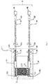
- the storage apparatus includes a storage warehouse 1 that stores articles 5 and a transfer apparatus 15 that transfers the articles 5, as illustrated in Fig. 1 .
- the storage warehouse 1 is, for example, a temperature-controlled furnace having a temperature-controlled space that houses the articles 5.
- the temperature-controlled furnace is, for example, a freeze-drying furnace.
- a shelf board 7 horizontally to the ground is disposed in the storage warehouse 1, and the articles 5 including an object to be freeze-dried are disposed on the shelf board 7.
- the articles 5 are, for example, vials containing a medicine poured therein.
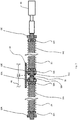
- the transfer apparatus 15 includes a first rod-shaped member 2A including a magnetic material, a first cover 20A configured to cover the first rod-shaped member 2A, a first terminal member 22A configured to allow insertion of a first end portion of the first rod-shaped member 2A, and a second terminal member 23A configured to allow insertion of a second end portion of the first rod-shaped member 2A.
- the first rod-shaped member 2A and the first terminal member 22A are not fixed. However, the first rod-shaped member 2A and the second terminal member 23A are fixed to each other.
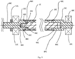
- the transfer apparatus 15 includes a second rod-shaped member 2C including a magnetic material, a second cover 20C configured to cover the second rod-shaped member 2C, a third terminal member 22C configured to allow insertion of a first end portion of the second rod-shaped member 2C, and a fourth terminal member 23C configured to allow insertion of a second end portion of the second rod-shaped member 2C.
- the first rod-shaped member 2A and an outer diameter of the second rod-shaped member 2C are the same.
- the first rod-shaped member 2A and the second rod-shaped member 2C are disposed so that a central axis of the first rod-shaped member 2A and a central axis of the second rod-shaped member 2C are aligned on an identical line.
- the second terminal member 23A and the third terminal member 22C are coupled by a coupling member 70.
- the coupling member 70 may be configured to allow coupling and separation according to opening and closing of a door of the temperature-controlled furnace.
- a driving device 4A is connected to the fourth terminal member 23C.
- the transfer apparatus 15 further includes an opposite member 3A that faces part of side surfaces of the first and second rod-shaped members 2A and 2C and including a magnetic material as illustrated in Fig. 1 .
- the opposite member 3A moves along the central axes of the first and second rod-shaped members 2A and 2C.
- the transfer apparatus 15 further includes a first rod-shaped member 2B disposed in parallel to the first rod-shaped member 2A and a second rod-shaped member 2D disposed in parallel to the second rod-shaped member 2C.
- first rod-shaped member 2B is covered with a first cover, and the first and second terminal members are inserted respectively into both ends of the first rod-shaped member 2B.
- the first rod-shaped member 2B and the first terminal member are not fixed. However, the first rod-shaped member 2B and the second terminal member are fixed to each other.
- the second rod-shaped member 2D is covered with a second cover, and the third and fourth terminal members are inserted respectively into both ends of the second rod-shaped member 2D.
- a driving device 4B is connected to a fourth terminal member.
- the second rod-shaped member 2D is inserted into the fourth terminal member.
- the driving device 4B rotates the fourth terminal member about the central axes of the first and second rod-shaped members 2B and 2D as an axis of rotation, the second rod-shaped member 2D, the third terminal member, the second terminal member, the first rod-shaped member 2B, and the first terminal member rotate simultaneously.
- sides of the second rod-shaped members 2C and 2D connected to the driving devices 4A and 4B may be referred to as a driven side
- sides of the second rod-shaped members 2C and 2D connected to the first rod-shaped members 2A and 2B may be referred to as a coupling side
- sides of the first rod-shaped members 2A and 2B connected to the second rod-shaped members 2C and 2D may be referred to as a coupling side
- sides opposite to the coupling sides of the first rod-shaped members 2A and 2B may be referred to as an non-driven side.
- the transfer apparatus 15 further includes an opposite member 3B that faces part of side surfaces of the first and second rod-shaped members 2B and 2D and including a magnetic material.
- an opposite member 3B that faces part of side surfaces of the first and second rod-shaped members 2B and 2D and including a magnetic material.
- a contact member 6 is connected to the opposite members 3A and 3B.
- the contact member 6 moves following a change in relative position of the rod-shaped members 2A and 2B and the opposite member 3A and 3B.
- the contact member 6 makes contact with the articles 5 to move the articles 5.
- the contact member 6 is disposed in a vertical direction with respect to the central axes of the first and second rod-shaped members 2A and 2C.
- first rod-shaped members 2A and 2B are disposed inside the storage warehouse 1 having a significant temperature change.
- the second rod-shaped members 2C and 2D and the driving devices 4A and 4B are disposed in a space outside the storage warehouse 1.
- the first rod-shaped member 2A is a magnetic screw including a magnetic material, and the outer peripheral surface thereof is threaded in a spiral shape.
- a second end portion of the first rod-shaped member 2A is provided with a projection 83A.
- An outer shape of the projection 83A is a circle and has an outer periphery smaller than the outer diameter of the main body of the first rod-shaped member 2A.
- the central axis of the projection 83A is aligned with the central axis of the main body of the first rod-shaped member 2A.
- the first cover 20A is, for example, a thin-walled pipe of a nonmagnetic material made of stainless steel, aluminum, resin, or the like.
- the first rod-shaped member 2A is inserted into the first cover 20A having a cylindrical shape.
- the central axis of the first rod-shaped member 2A is aligned with the central axis of the first cover 20A.
- the first cover 20A also rotates about the central axis of the first rod-shaped member 2A.
- the first terminal member 22A has a concave portion 84A therein and includes an engagement portion 86A having a part with an outer diameter identical to that of the first cover 20A and a mandrel portion 88A having a shape of a projection with an outer diameter smaller than an outer diameter of the engagement portion 86A.
- the engagement portion 86A and the mandrel portion 88A are integrated with each other.
- the outer shapes of the engagement portion 86A and the mandrel portion 88A are circles and the center of the outer shape of the engagement portion 86A and the center of the outer shape of the mandrel portion 88A are aligned on an identical line.
- the first terminal member 22A is made of a nonmagnetic material such as stainless steel, aluminum, or resin.
- the concave portion 84A of the first terminal member 22A has a circular cross section and has an inner diameter identical to an outer diameter of the first end portion of the first rod-shaped member 2A.
- the first end portion of the first rod-shaped member 2A is inserted into the concave portion 84A of the first terminal member 22A.
- an insertion depth of the first end portion of the first rod-shaped member 2A is smaller than the depth of the concave portion 84A of the first terminal member 22A. Accordingly, a space is provided between an end surface of the first end portion of the first rod-shaped member 2A and a bottom surface of the concave portion 84A.
- the end surface surrounding the concave portion 84A of the first terminal member 22A does not make contact with the first rod-shaped member 2A.
- the end surface is a surface orthogonal to the central axis of the first rod-shaped member 2A and the same applies to the following description.
- the engagement portion 86A of the first terminal member 22A is provided with a step having a height identical to the thickness of the first cover 20A.
- the outer shape of the step portion is also a circle.
- An outer diameter of the part of the engagement portion 86A reduced in diameter by the step is identical to the inner diameter of the first cover 20A.
- the outer diameter of the part of the engagement portion 86A increased in diameter by the step is identical to the outer diameter of the first cover 20A.
- the part of the engagement portion 86A of the first terminal member 22A reduced in diameter by the step is inserted inside the first cover 20A.
- the second terminal member 23A has a concave portion 85A therein and includes an engagement portion 87A having a part with an outer diameter identical to the outer diameter of the first cover 20A and a mandrel portion 89A having a shape of a projection with an outer diameter smaller than the outer diameter of the engagement portion 87A.
- the engagement portion 87A and the mandrel portion 89A are integrated with each other.
- the outer shapes of the engagement portion 87A and the mandrel portion 89A are circles and the center of the outer shape of the engagement portion 87A and the center of the outer shape of the mandrel portion 89A are aligned on an identical line.
- the second terminal member 23A is made of a nonmagnetic material such as stainless steel, aluminum, resin or the like.
- the concave portion 85A of the second terminal member 23A has a circular cross section and has an inner diameter identical to the outer diameter of the projection 83A at the second end portion of the first rod-shaped member 2A.
- the projection 83A of the second end portion of the first rod-shaped member 2A is inserted into the concave portion 85A of the second terminal member 23A.
- an insertion depth of the projection 83A of the second end portion of the first rod-shaped member 2A is smaller than the depth of the concave portion 85A of the second terminal member 23A. Therefore, a space is provided between the end surface of the projection 83A of the first rod-shaped member 2A and the bottom surface of the concave portion 85A of the second terminal member 23A.
- the engagement portion 87A of the second terminal member 23A is provided with a step having a height identical to the thickness of the first cover 20A.
- the outer shape of the step portion is a circle.
- the outer diameter of the part of the engagement portion 87A reduced in diameter by the step is identical to the inner diameter of the first cover 20A.
- the outer diameter of the part of the engagement portion 87A increased in diameter by the step is identical to the outer diameter of the first cover 20A.
- the part of the engagement portion 87A of the second terminal member 23A reduced in diameter by the step is inserted inside the first cover 20A.
- the mandrel portion 89A of the second terminal member 23A penetrates through a hole provided in a side wall of the storage warehouse 1 illustrated in Fig. 1 .
- the hole of the side wall of the storage warehouse 1 configured to allow the mandrel portion 89A to pass through is provided with a sealing member such as an oil seal.
- the transfer apparatus 15 further includes a first bearing 12Athat receives a load of the mandrel portion 88A of the first terminal member 22A and a second bearing 13A that receives a load of the mandrel portion 89A of the second terminal member 23A as illustrated in Fig. 5 .
- the first bearing 12A and the second bearing 13A are disposed in the storage warehouse 1 illustrated in Fig. 1 , for example.
- the second bearing 13A is tightened by a bearing nut 52A so that an end surface of the second terminal member 23A formed by the step between the engagement portion 87A and the mandrel portion 89A makes contact with the end surface of the second bearing 13A. This prevents or reduces misalignment caused by expansion and contraction in a direction of a central axis of the first rod-shaped member 2A on the coupling side.
- a space is provided between the end surface of the first terminal member 22A formed by a step between the engagement portion 86A and the mandrel portion 88A and the end surface of the first bearing 12A, and the first bearing 12A is not tightened by the bearing nut. This allows the first rod-shaped member 2A to expand and contract in the direction of the central axis on the non-driven side.
- a portion 43A at a point of contact between the end portion of the first cover 20A and the step portion of the engagement portion 87A of the second terminal member 23A is fixed by welding.
- a portion 44A at a point of contact between the end surface of the first rod-shaped member 2A formed by the step between the main body and the projection 83A and the end surface surrounding the concave portion 85A of the engagement portion 87A of the second terminal member 23A is fixed by welding. Since the end surfaces are fixed to each other on the coupling side, misalignment of the first rod-shaped member 2A due to expand and contract in the direction of the central axis is prevented or reduced.
- a portion 42A at a point of contact between the end portion of the first cover 20A and the step portion of the engagement portion 86A of the first terminal member 22A is fixed by welding.
- the first end portion of the first rod-shaped member 2A and the first terminal member 22A are not fixed to each other by welding or the like and the first rod-shaped member 2A and the first terminal member 22A are integrated with each other only by a friction force.
- the second rod-shaped member 2C is a magnetic screw including a magnetic material and is provided with a thread in a spiral shape on an outer peripheral surface.
- a first end portion of the second rod-shaped member 2C is provided with a projection 83C.
- the outer shape of the projection 83C is a circle and has an outer periphery smaller than the outer diameter of a main body of the second rod-shaped member 2C.
- the central axis of the projection 83C is aligned with the central axis of the main body of the second rod-shaped member 2C.
- the second cover 20C is, for example, a thin-walled pipe of a nonmagnetic material made of stainless steel, aluminum, resin, or the like.
- the second rod-shaped member 2C is inserted into the second cover 20C having a cylindrical shape.
- the central axis of the second rod-shaped member 2C is aligned with the central axis of the second cover 20C.
- the second cover 20C also rotates about the central axis of the second rod-shaped member 2C.
- the third terminal member 22C has a concave portion 84C therein and includes an engagement portion 86C having a part with an outer diameter identical to the outer diameter of the second cover 20C and a mandrel portion 88C having a shape of a projection with an outer diameter smaller than the outer diameter of the engagement portion 86C.
- the engagement portion 86C and the mandrel portion 88C are integrated with each other.
- the outer shapes of the engagement portion 86C and the mandrel portion 88C are circles and the center of the outer shape of the engagement portion 86C and the center of the outer shape of the mandrel portion 88C are aligned on an identical line.
- the third terminal member 22C is made of a nonmagnetic material such as stainless steel, aluminum, or resin.
- the concave portion 84C of the third terminal member 22C has a circular cross section and has an inner diameter identical to the outer diameter of the projection 83C of the first end portion of the second rod-shaped member 2C.
- the projection 83C of the first end portion of the second rod-shaped member 2C is inserted into the concave portion 84C of the third terminal member 22C.
- an insertion depth of the projection 83C at the first end portion of the second rod-shaped member 2C is smaller than the depth of the concave portion 84C of the third terminal member 22C. Therefore, a space is provided between the end surface of the projection 83C of the second rod-shaped member 2C and a bottom surface of the concave portion 84C of the third terminal member 22C.
- the engagement portion 86C of the third terminal member 22C is provided with a step having the height identical to the thickness of the second cover 20C.
- the outer shape of the step portion is a circle.
- the outer diameter of the part of the engagement portion 86C reduced in diameter by the step is identical to the inner diameter of the second cover 20C.
- the outer diameter of the part of the engagement portion 86C increased in diameter by the step is identical to the outer diameter of the second cover 20C.
- the part of the engagement portion 86C of the third terminal member 22C reduced in diameter by the step is inserted inside the second cover 20C.
- the fourth terminal member 23C has a concave portion 85C therein and includes an engagement portion 87C having a part with an outer diameter identical to the outer diameter of the second cover 20C and a mandrel portion 89C having a shape of a projection with an outer diameter smaller than in the engagement portion 87C.
- the engagement portion 87C and the mandrel portion 89C are integrated with each other.
- the outer shapes of the engagement portion 87C and the mandrel portion 89C are circles and the center of the outer shape of the engagement portion 87C and the center of the outer shape of the mandrel portion 89C are aligned on an identical line.
- the fourth terminal member 23C is made of a nonmagnetic material such as stainless steel, aluminum, resin or the like.
- the concave portion 85C of the fourth terminal member 23C has a circular cross section and has an inner diameter identical to the outer diameter of the second end portion of the second rod-shaped member 2C.
- the second end portion of the second rod-shaped member 2C is inserted into the concave portion 85C of the fourth terminal member 23C.
- an insertion depth of the second end portion of the second rod-shaped member 2C is smaller than the depth of the concave portion 85C of the fourth terminal member 23C. Accordingly, a space is provided between an end surface of the second end portion of the second rod-shaped member 2C and the bottom surface of the concave portion 85C.
- the end surface surrounding the concave portion 85C of the fourth terminal member 23C does not make contact with the second rod-shaped member 2C.
- the engagement portion 87C of the fourth terminal member 23C is provided with a step having the height identical to the thickness of the second cover 20C.
- the outer shape of the step portion is also a circle.
- the outer diameter of the part of the engagement portion 87C reduced in diameter by the step is identical to the inner diameter of the second cover 20C.
- the outer diameter of the part of the engagement portion 87C increased in diameter by the step is identical to the outer diameter of the second cover 20C.
- the part of the engagement portion 87C of the fourth terminal member 23C reduced in diameter by the step is inserted inside the second cover 20C.
- the transfer apparatus 15 further includes a third bearing 12C that receives a load of the mandrel portion 88C of the third terminal member 22C and a fourth bearing 13C that receives a load of the mandrel portion 89C of the fourth terminal member 23C.
- the third bearing 12C is tightened by a bearing nut 52C so that an end surface formed by the engagement portion 86C of the third terminal member 22C and a step of the mandrel portion 88C makes contact with an end surface of the third bearing 12C. This prevents or reduces misalignment caused by expansion and contraction in a direction of a central axis of the second rod-shaped member 2C on the coupling side.
- a space is provided between the end surface of the fourth terminal member 23C formed by a step between the engagement portion 87C and the mandrel portion 89C and the end surface of the fourth bearing 13C, and the fourth bearing 13C is not tightened by the bearing nut. This allows the second rod-shaped member 2C to expand and contract in the direction of the central axis on the driven side.
- a portion 42C at a point of contact between the end portion of the second cover 20C and the step portion of the engagement portion 86C of the third terminal member 22C is fixed by welding.
- a portion 44C at a point of contact between the end surface of the second rod-shaped member 2C formed by the step between the main body and the projection 83C of the second rod-shaped member 2C and the end surface surrounding the concave portion 84C of the engagement portion 86C of the third terminal member 22C is fixed by welding. Since the end surfaces are fixed on the coupling side, misalignment of the second rod-shaped member 2C in the direction of the central axis caused by expansion and contraction is prevented or reduced.
- a portion 43C at a point of contact between the end portion of the second cover 20C and the step portion of the engagement portion 87C of the fourth terminal member 23C is fixed by welding.
- the second end portion of the second rod-shaped member 2C and the fourth terminal member 23C are not fixed to each other by welding or the like and the second rod-shaped member 2C and the fourth terminal member 23C are integrated with each other only by a friction force.
- the opposite member 3A illustrated in Fig. 1 is a magnetic nut including a magnetic material and provided with a hole having an inner circumference larger than outer circumferences of the first and second rod-shaped members 2A and 2C.
- the first and second rod-shaped members 2A and 2C penetrate through a hole in the opposite member 3A having a nut shape.
- the opposite member 3A may be supported by a guide 60.
- S pole magnetized zones and N pole magnetized zones are alternately provided in a spiral shape on an inner peripheral surface of the hole in the opposite member 3A.
- the pitch of the magnetized zones of the opposite member 3A is substantially identical to the pitch of the threads of the first and second rod-shaped members 2A and 2C.
- Guide rings 31 and 32 such as bushes may be provided on the inner peripheral surface of the opposite member 3A.
- the inner circumferences of the guide rings 31 and 32 are smaller than the inner circumference of the opposite member 3A and make contact with the outer peripheral surface of the first and second covers 20A and 20C. Therefore, a constant interval is kept between the threads of the first and second rod-shaped members 2A and 2C and the magnetized zones of the opposite member 3A.
- the guide rings 31 and 32 are made of a material having a small friction coefficient, such as fluororesin.
- the first rod-shaped member 2A and the second rod-shaped member 2C illustrated in Fig. 2 are connected in such a manner that the thread pitch of an extended screw shaft matches the screw pitch of the second rod-shaped member 2C and does not cause any misalignment even when the screw shaft of the first rod-shaped member 2A is extended. Accordingly, the opposite member 3A is allowed to move smoothly from the first rod-shaped member 2A to the second rod-shaped member 2C, or from the second rod-shaped member 2C to the first rod-shaped member 2A at a coupling portion between the first rod-shaped member 2A and the second rod-shaped member 2C.
- the first rod-shaped member 2B is held by a first bearing 12B and a second baring 13B in parallel with the first rod-shaped member 2A in the storage warehouse 1.
- the second rod-shaped member 2D is held by a third bearing 12D and a fourth bearing 13D in parallel with the second rod-shaped member 2C.
- a configuration of the opposite member 3B is identical to that of the opposite member 3A.
- the contact member 6 is a plate member and is fixed between the opposite member 3A and the opposite member 3B so as to be substantially orthogonal to the surface of the shelf board 7.
- the driving devices 4A and 4B include, for example, rotating motors, and are disposed outside a temperature controlled space in the storage warehouse 1.
- the driving devices 4A and 4B may be covered with a shield or the like which prevents diffusion of possible dust or the like.
- the driving device 4A and the second rod-shaped member 2C are connected, for example, via the mandrel portion 89C of the fourth terminal member 23C illustrated in Fig. 9 .
- the driving device 4B and the second rod-shaped member 2D illustrated in Fig. 1 are connected via a mandrel portion of the fourth terminal member with the second rod-shaped member 2D inserted.
- the driving devices 4Aand 4B rotate the first and second rod-shaped members 2A, 2B, 2C, and 2D in synchronization with each other.
- a magnetic force acts between the threads of the first and second rod-shaped members 2A and 2C and the magnetized zones of the opposite member 3A.
- the opposite member 3A is fixed to the contact member 6 and the opposite member 3B and cannot rotate. Therefore, when the first and second rod-shaped members 2A and 2C rotate, the opposite member 3A moves along the central axes of the first and second rod-shaped members 2Aand 2C.
- the driving device 4B rotates the first and second rod-shaped members 2B and 2D
- a magnetic force acts between the threads of the first and second rod-shaped members 2B and 2D and the magnetized zones of the opposite member 3B
- the opposite member 3B moves along the central axis of the first and second rod-shaped members 2B and 2D.
- the contact member 6 fixed between the opposite members 3A and 3B also moves along the central axes of the first and second rod-shaped members 2A, 2B, 2C, and 2D on the shelf board 7 as the opposite members 3A and 3B move.
- the articles 5 placed on the shelf board 7 are pushed by the contact member 6 and move on the shelf board 7. Furthermore, the articles 5 may be pushed to the outside of the storage warehouse 1 through the door of the storage warehouse 1.
- the heat expansion ratio of the first rod-shaped member 2A including a magnetic material illustrated in Fig. 6 is different from the heat expansion ratios of the first cover 20A, the first terminal member 22A, and the second terminal member 23A that are made of a nonmagnetic material.
- the rod-shaped member 2A is allowed to expand and contract on the non-driven side, a stress that may be caused by differences in heat expansion ratios may be alleviated.
- first rod-shaped member 2A and the second rod-shaped member 2C illustrated in Fig. 2 are connected in such a manner that the thread pitch of an extended screw shaft matches the screw pitch of the second rod-shaped member 2C and does not cause any misalignment even when the screw shaft of the first rod-shaped member 2A is extended.
- the space between the first rod-shaped member 2A and the second rod-shaped member 2C may vary.
- the tread pitch of the extended screw shaft and the screw pitch of the second rod-shaped member 2C may be misaligned even when the screw shaft of the first rod-shaped member 2A is extended, and thus the opposite member 3A may have a difficulty to move smoothly at a coupling portion between the first rod-shaped member 2A and the second rod-shaped member 2C.
- the heat expansion ratio of the second rod-shaped member 2C including a magnetic material illustrated in Fig. 9 is different from the heat expansion ratios of the second cover 20C, the third terminal member 22C, and the fourth terminal member 23C that are made of a nonmagnetic material. However, since the second rod-shaped member 2C is allowed to expand and contract on the non-driven side, a stress that may be caused by difference in heat expansion ratios may be alleviated.
- the driving torque is transmitted between the first and second rod-shaped members 2A and 2C and the opposite member 3A, and between the first and second rod-shaped members 2B and 2D and the opposite member 3B in a non-contact manner by a magnetic force. Therefore, generation of heat and dust is reduced during driving force transmission between the first and second rod-shaped members 2A and 2C and the opposite member 3A, and between the first and second rod-shaped members 2B and 2D and the opposite member 3B. Accordingly, even if the opposite members 3A and 3B move in the temperature-controlled space in the storage warehouse 1, an influence of heat generation in the temperature-controlled space may be prevented or reduced and the temperature-controlled space may be kept clean.
- the driving devices 4A and 4B are disposed outside the temperature-controlled space in the storage warehouse 1, even if dust is generated in the driving devices 4A and 4B, the dust is unlikely to enter the temperature-controlled space in the storage warehouse 1.
- the temperature distribution may become uneven in the temperature-controlled furnace such as a freeze drying furnace due to the heated driving devices. In this case, the quality of multiple articles disposed in the temperature-controlled furnace may become uneven.
- the driving devices 4A and 4B are disposed outside the temperature-controlled space in the storage warehouse 1, the temperature is unlikely to become uneven in the storage warehouse 1.
- Fig. 1 an example in which the first rod-shaped members 2A and 2B are disposed in the interior of the storage warehouse 1, and the second rod-shaped members 2C and 2D are disposed outside the storage warehouse 1 has been described.
- the second rod-shaped members 2C and 2D may also be provided inside the storage warehouse 1.
- Fig. 1 illustrates an example in which the driving devices 4A and 4B are connected to the fourth terminal member configured to allow insertion of the second end portions of the second rod-shaped members 2C and 2D.
- the driving devices 4A and 4B may be connected to the first terminal member that allows insertion of the first rod-shaped members 2A and 2B.
- Fig. 9 illustrates an example in which the second end portion of the second rod-shaped member 2C and the fourth terminal member 23C are not fixed on the driven side, and thus is allowed to be expanded and contracted in a direction of the central axis of the second rod-shaped member 2C.
- the space where the second rod-shaped member 2C is disposed is a space having less temperature change, and if expansion and contraction of the second rod-shaped member 2C can hardly occur, the second end portion of the second rod-shaped member 2C and the fourth terminal member 23C may be fixed.
- the second rod-shaped member 2D illustrated in Fig. 1 illustrates an example in which the second end portion of the second rod-shaped member 2C and the fourth terminal member 23C are not fixed on the driven side, and thus is allowed to be expanded and contracted in a direction of the central axis of the second rod-shaped member 2C.
- the space where the second rod-shaped member 2C is disposed is a space having less temperature change, and if expansion and contraction of the second rod-shaped member 2
- Fig. 6 illustrates an example in which the portion 44A at a point of contact between the first rod-shaped member 2A and the engagement portion 87A of the second terminal member 23A is fixed by welding on the coupling side
- the fixation method is not limited to welding.
- the first rod-shaped member 2A and the second terminal member 23A may be fixed to each other by a fastening pin 62A on the coupling side.
- a through-hole is provided in the projection 83A of the second end portion of the first rod-shaped member 2A, and a through-hole is also provided in the engagement portion 87A of the second terminal member 23A.
- the fastening pin 62A is then inserted so as to penetrate both through the through-hole in the projection 83A of the first rod-shaped member 2A and the through-hole in the engagement portion 87A of the second terminal member 23A to prevent or reduce expansion and contraction of the first rod-shaped member 2A in the direction of the central axis.
- a portion at a point of contact between the first cover 20A and the engagement portion 87A of the second terminal member 23A may be fixed by welding on the coupling side.
- the first rod-shaped member 2A and the first terminal member 22A may make contact with each other via a key 63A on the non-driven side.
- the key 63A is fitted into a key groove provided in the first end portion of the first rod-shaped member 2A.
- the key 63A suppresses slippage of the first terminal member 22A when the first rod-shaped member 2A rotates, the key 63A allows the first rod-shaped member 2A to expand and contract in the direction of the central axis.
- a portion at a point of contact between the first cover 20A and the engagement portion 86A of the first terminal member 22A may be fixed by welding on the non-driven side.
- the fastening pin 62C is then inserted so as to penetrate both through the through-hole in the projection 83C of the second rod-shaped member 2C and the through-hole in the engagement portion 86C of the third terminal member 22C to prevent or reduce expansion and contraction of the second rod-shaped member 2C in the direction of the central axis.
- a portion at a point of contact between the second cover 20C and the engagement portion 86C of the third terminal member 22C may be fixed by welding on the coupling side.
- the second rod-shaped member 2C and the fourth terminal member 23C may make contact with each other via a key 63C on the driven side.
- the key 63C is fitted into a key groove provided in the second end portion of the second rod-shaped member 2C.
- the key 63C prevents or reduces slippage of the second rod-shaped member 2C when the fourth terminal member 23C rotates, the key 63C allows the second rod-shaped member 2C to expand and contract in the direction of the central axis.
- a portion at a point of contact between the second cover 20C and the engagement portion 87C of the fourth terminal member 23C may be fixed by welding on the driven side.
- Fig. 3 to Fig. 6 illustrate the first rod-shaped member 2A provided with threads.
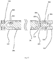
- the outer peripheral surface of the first rod-shaped member 2A may be provided with S pole magnetized zones and N pole magnetized zones alternately in a spiral shape.
- the pitch of the magnetized zones of the first rod-shaped member 2A illustrated in Fig. 15 is substantially identical to the pitch of the magnetized zones of the opposite member 3A.
- the opposite member 3A may be a threaded magnetic material.
- the surface of a threaded hole in the opposite member 3A may be covered with a thin-walled pipe 30A formed of a nonmagnetic material. This can prevent foreign matters from adhering to a threaded groove of the opposite member 3A.
- the structure of the first rod-shaped member 2A is identical to that of Fig. 15 .
- the pitch of the threads of the opposite member 3A illustrated in Fig. 16 is substantially identical to the pitch of the magnetized zones of the first rod-shaped member 2A.
- the shape of the opposite member is not limited to the nut shape, but may be, for example, a concave shape.
- the rod-shaped member passes through the concave portion of the concave opposite member.
- S pole magnetized zones and N pole magnetized zones are alternately provided on the side surface of the concave portion of the concave opposite member.
- the storage warehouse may be a sterilization processing furnace or a fermenting furnace or may be a storage warehouse that does not undergo temperature control.
- the articles transferred to the inside and the outside of the storage warehouse are not limited to medicines, but may include foods, beverages, precision parts, etc., as well as any articles.
- the transfer apparatus is not necessarily combined with the storage warehouse. As described above, it should be understood that the invention encompasses various embodiments and the like not described in the specification.
Landscapes
- Engineering & Computer Science (AREA)
- General Engineering & Computer Science (AREA)
- Mechanical Engineering (AREA)
- Transmission Devices (AREA)
- Dynamo-Electric Clutches, Dynamo-Electric Brakes (AREA)
Abstract
Description
- The present invention relates to a transfer technique, more particularly, to a transfer apparatus.
- In a transfer apparatus using a magnetic screw, a male screw made of a magnetic material is rotated to move a nut made of a magnetic material in a direction of a central axis of the male screw. The male screw made of a magnetic material may be covered with a cover having a cylindrical shape and made of a nonmagnetic material so as to move the nut smoothly or prevent corrosion of the male screw (for example, see PTL 1). In order to avoid contact between the male screw and the nut due to flexure of the male screw, the male screw is sometimes divided for installation (for example, see PTL 2).
-
- PTL 1: Japanese Patent No.
2937883 - PTL 2: Japanese Patent No.
3122367 - Mandrels made of a nonmagnetic material are connected to both ends of a male screw made of a magnetic material and a driving device for rotating the male screw may be connected to one of the mandrels. The male screw may be divided for installation in order to alleviate flexure due to a magnetic force or its own weight. Here, a heat expansion ratio of the male screw made of a magnetic material is different from the heat expansion ratio of the cover or the mandrel made of a nonmagnetic material. Accordingly, when the male screw is fixed to the cover and the mandrel completely, a stress is generated due to a difference in heat expansion ratios. Accordingly distortion or breakage may result. Therefore, the stress generated due to the heat may be alleviated by fixing one of each of the male screws, the mandrels, and the covers, and leaving the other one of each of those members free. However, the inventors have found that this method of fixation may reduce a thrust force that can be generated by a magnetic screw at a male screw coupling portion and may cause an unstable operation. Accordingly, it is one of objects of the present invention to provide a transfer apparatus capable of alleviating a stress that may be generated due to thermal expansion and contraction without reducing a thrust force generated at a male screw coupling portion.
- According to an aspect of the present invention, there is provided a transfer apparatus including: (a) a first rod-shaped member including a magnetic material; (b) a first terminal member configured to allow insertion of a first end portion of the first rod-shaped member; (c) a second terminal member configured to allow insertion of a second end portion of the first rod-shaped member; (d) a second rod-shaped member including a magnetic material; (e) a third terminal member configured to allow insertion of a first end portion of the second rod-shaped member; (f) a fourth terminal member configured to allow insertion of a second end portion of the second rod-shaped member; (g) a coupling member configured to couple the second terminal member and the third terminal member; and (h) an opposite member facing part of side surfaces of the first and second rod-shaped members and including a magnetic material, wherein (i) the first rod-shaped member and the first terminal member are not fixed, (j) the first rod-shaped member and the second terminal member are fixed to each other, and (k) when the first and second rod-shaped members rotate, the opposite member moves along central axes of the first and second rod-shaped members.
- In the transfer apparatus described above, a concave portion configured to allow insertion of the first end portion of the first rod-shaped member may be provided in the first terminal member, and an insertion depth of the first end portion of the first rod-shaped member may be smaller than a depth of the concave portion of the first terminal member, so that an end surface surrounding the concave portion of the first terminal member does not have to make contact with the first rod-shaped member.
- In the transfer apparatus described above, the first rod-shaped member and the second terminal member may be fixed to each other by welding. Alternatively, the first rod-shaped member and the second terminal member may be fixed to each other by a fastening pin. The first rod-shaped member may make contact with the first terminal member via a key.
- As an alternative configuration of the transfer apparatus described above, the transfer apparatus further includes a first cover formed of a nonmagnetic material and configured to cover the first rod-shaped member, the first cover and the first terminal member are fixed to each other, and the first cover and the second terminal member are fixed to each other. As an alternative configuration of the transfer apparatus, the first cover and the first terminal member are fixed to each other by welding, and the first cover and the second terminal member are fixed to each other by welding.
- As an alternative configuration of the transfer apparatus described above, the first terminal member and the second terminal member may be made of a nonmagnetic material.
- As an alternative configuration of the transfer apparatus described above, the second rod-shaped member and the third terminal member are fixed to each other, and the second rod-shaped member and the fourth terminal member are not fixed.
- In the transfer apparatus described above, a concave portion configured to allow insertion of the second end portion of the second rod-shaped member may be provided in the fourth terminal member, and an insertion depth of the second end portion of the second rod-shaped member may be smaller than a depth of the concave portion of the fourth terminal member, so that an end surface surrounding the concave portion of the fourth terminal member does not have to make contact with the second rod-shaped member.
- In the transfer apparatus described above, the second rod-shaped member and the third terminal member may be fixed to each other by welding. Alternatively, the second rod-shaped member and the third terminal member may be fixed to each other by a fastening pin. The second rod-shaped member may make contact with the fourth terminal member via a key.
- As an alternative configuration of the transfer apparatus described above, the transfer apparatus further includes a second cover formed of a nonmagnetic material and configured to cover the second rod-shaped member, the second cover and the third terminal member are fixed, and the second cover and the fourth terminal member are fixed. As an alternatively configuration of the transfer apparatus, the second cover and the first terminal member are fixed by welding, and the second cover and the second terminal member are fixed to each other by welding.
- In the transfer apparatus described above, the third terminal member and the fourth terminal member may be made of a nonmagnetic material.
- In the transfer apparatus described above, the first rod-shaped member may be stored in a furnace. The first and second rod-shaped members may be store in the furnace.
- As an alternative configuration of the transfer apparatus described above, the transfer apparatus further includes a driving device connected to the first terminal member, and the driving device is configured to rotate the first and second rod-shaped members about central axes of the first and second rod-shaped members. As an alternative configuration of the transfer apparatus described above, the transfer apparatus further includes a driving device connected to the fourth terminal member, and the driving device is configured to rotate the first and second rod-shaped members about the central axes of the first and second rod-shaped members.
- The invention may provide a transfer apparatus capable of alleviating a stress that may be caused by heat expansion and contraction.
-
-
Fig. 1 is a schematic plan view illustrating a storage apparatus according to an embodiment of the invention. -
Fig. 2 is a schematic cross-sectional view illustrating a transfer apparatus according to the embodiment of the invention. -
Fig. 3 is a schematic cross-sectional view illustrating a first rod-shaped member according to the embodiment of the invention. -
Fig. 4 is a schematic cross-sectional view illustrating the first rod-shaped member and an opposite member according to the embodiment of the invention. -
Fig. 5 is a schematic cross-sectional view illustrating the first rod-shaped member according to the embodiment of the invention. -
Fig. 6 is a schematic cross-sectional view illustrating the first rod-shaped member according to the embodiment of the invention. -
Fig. 7 is a schematic cross-sectional view illustrating a second rod-shaped member according to the embodiment of the invention. -
Fig. 8 is a schematic cross-sectional view illustrating the second rod-shaped member according to the embodiment of the invention. -
Fig. 9 is a schematic cross-sectional view illustrating the second rod-shaped member according to the embodiment of the invention. -
Fig. 10 is a schematic cross-sectional view illustrating a transfer apparatus according to a third modification of the embodiment of the invention. -
Fig. 11 is a schematic cross-sectional view illustrating a first rod-shaped member according to the third modification of the embodiment of the invention. -
Fig. 12 is a schematic cross-sectional view illustrating the first rod-shaped member according to the third modification of the embodiment of the invention. -
Fig. 13 is a schematic cross-sectional view illustrating a second rod-shaped member according to the third modification of the embodiment of the invention. -
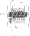
Fig. 14 is a schematic cross-sectional view illustrating the second rod-shaped member according to the third modification of the embodiment of the invention. -
Fig. 15 is a schematic view illustrating a first rod-shaped member and an opposite member according to a fourth modification of the embodiment of the invention. -
Fig. 16 is a schematic view illustrating the first rod-shaped member and the opposite member according to the fourth modification of the embodiment of the invention. - Embodiments of the invention will be described below. In the description of the drawings given below, the same or similar parts are denoted by the same or similar reference numerals. However, the drawings are schematically illustrated. Therefore, specific dimensions and the like should be determined with reference to the following description. It will be appreciated that the relationship or ratio between dimensions may be different among the drawings.
- The storage apparatus according to the embodiment of the invention includes a storage warehouse 1 that stores
articles 5 and atransfer apparatus 15 that transfers thearticles 5, as illustrated inFig. 1 . The storage warehouse 1 is, for example, a temperature-controlled furnace having a temperature-controlled space that houses thearticles 5. The temperature-controlled furnace is, for example, a freeze-drying furnace. For example, a shelf board 7 horizontally to the ground is disposed in the storage warehouse 1, and thearticles 5 including an object to be freeze-dried are disposed on the shelf board 7. Thearticles 5 are, for example, vials containing a medicine poured therein. - As illustrated in
Fig. 2 , thetransfer apparatus 15 includes a first rod-shapedmember 2A including a magnetic material, afirst cover 20A configured to cover the first rod-shapedmember 2A, afirst terminal member 22A configured to allow insertion of a first end portion of the first rod-shapedmember 2A, and asecond terminal member 23A configured to allow insertion of a second end portion of the first rod-shapedmember 2A. The first rod-shapedmember 2A and thefirst terminal member 22A are not fixed. However, the first rod-shapedmember 2A and thesecond terminal member 23A are fixed to each other. Thetransfer apparatus 15 includes a second rod-shapedmember 2C including a magnetic material, asecond cover 20C configured to cover the second rod-shapedmember 2C, athird terminal member 22C configured to allow insertion of a first end portion of the second rod-shapedmember 2C, and afourth terminal member 23C configured to allow insertion of a second end portion of the second rod-shapedmember 2C. - An outer diameter of the first rod-shaped
member 2A and an outer diameter of the second rod-shapedmember 2C are the same. The first rod-shapedmember 2A and the second rod-shapedmember 2C are disposed so that a central axis of the first rod-shapedmember 2A and a central axis of the second rod-shapedmember 2C are aligned on an identical line. Thesecond terminal member 23A and thethird terminal member 22C are coupled by acoupling member 70. Thecoupling member 70 may be configured to allow coupling and separation according to opening and closing of a door of the temperature-controlled furnace. - A
driving device 4A is connected to thefourth terminal member 23C. When thedriving device 4A causes thefourth terminal member 23C to rotate about the central axes of the first and second rod-shapedmembers member 2C, thethird terminal member 22C, thesecond terminal member 23A, the first rod-shapedmember 2A, and thefirst terminal member 22A rotate simultaneously. Thetransfer apparatus 15 further includes anopposite member 3A that faces part of side surfaces of the first and second rod-shapedmembers Fig. 1 . When the first and second rod-shapedmembers opposite member 3A moves along the central axes of the first and second rod-shapedmembers - The
transfer apparatus 15 further includes a first rod-shapedmember 2B disposed in parallel to the first rod-shapedmember 2A and a second rod-shaped member 2D disposed in parallel to the second rod-shapedmember 2C. Although not illustrated in the drawing, in the same manner as the first rod-shapedmember 2A, the first rod-shapedmember 2B is covered with a first cover, and the first and second terminal members are inserted respectively into both ends of the first rod-shapedmember 2B. The first rod-shapedmember 2B and the first terminal member are not fixed. However, the first rod-shapedmember 2B and the second terminal member are fixed to each other. In the same manner as the second rod-shapedmember 2C, the second rod-shaped member 2D is covered with a second cover, and the third and fourth terminal members are inserted respectively into both ends of the second rod-shaped member 2D. - A driving
device 4B is connected to a fourth terminal member. The second rod-shaped member 2D is inserted into the fourth terminal member. When thedriving device 4B rotates the fourth terminal member about the central axes of the first and second rod-shapedmembers 2B and 2D as an axis of rotation, the second rod-shaped member 2D, the third terminal member, the second terminal member, the first rod-shapedmember 2B, and the first terminal member rotate simultaneously. - In the following description, sides of the second rod-shaped
members 2C and 2D connected to thedriving devices members 2C and 2D connected to the first rod-shapedmembers members members 2C and 2D may be referred to as a coupling side, and sides opposite to the coupling sides of the first rod-shapedmembers - The
transfer apparatus 15 further includes anopposite member 3B that faces part of side surfaces of the first and second rod-shapedmembers 2B and 2D and including a magnetic material. When the first and second rod-shapedmembers 2B and 2D rotate, theopposite member 3B moves along the central axes of the first and second rod-shapedmembers 2B and 2D. - A
contact member 6 is connected to theopposite members contact member 6 moves following a change in relative position of the rod-shapedmembers opposite member contact member 6 makes contact with thearticles 5 to move thearticles 5. Thecontact member 6 is disposed in a vertical direction with respect to the central axes of the first and second rod-shapedmembers - For example, the first rod-shaped
members members 2C and 2D and thedriving devices - As illustrated in
Fig. 3 and Fig. 4 , the first rod-shapedmember 2A is a magnetic screw including a magnetic material, and the outer peripheral surface thereof is threaded in a spiral shape. As illustrated inFig. 5 , a second end portion of the first rod-shapedmember 2A is provided with aprojection 83A. An outer shape of theprojection 83A is a circle and has an outer periphery smaller than the outer diameter of the main body of the first rod-shapedmember 2A. The central axis of theprojection 83A is aligned with the central axis of the main body of the first rod-shapedmember 2A. Thefirst cover 20A is, for example, a thin-walled pipe of a nonmagnetic material made of stainless steel, aluminum, resin, or the like. The first rod-shapedmember 2A is inserted into thefirst cover 20A having a cylindrical shape. The central axis of the first rod-shapedmember 2A is aligned with the central axis of thefirst cover 20A. When the first rod-shapedmember 2A rotates, thefirst cover 20A also rotates about the central axis of the first rod-shapedmember 2A. - The
first terminal member 22A has aconcave portion 84A therein and includes anengagement portion 86A having a part with an outer diameter identical to that of thefirst cover 20A and amandrel portion 88A having a shape of a projection with an outer diameter smaller than an outer diameter of theengagement portion 86A. Theengagement portion 86A and themandrel portion 88A are integrated with each other. The outer shapes of theengagement portion 86A and themandrel portion 88A are circles and the center of the outer shape of theengagement portion 86A and the center of the outer shape of themandrel portion 88A are aligned on an identical line. Thefirst terminal member 22A is made of a nonmagnetic material such as stainless steel, aluminum, or resin. - The
concave portion 84A of thefirst terminal member 22A has a circular cross section and has an inner diameter identical to an outer diameter of the first end portion of the first rod-shapedmember 2A. The first end portion of the first rod-shapedmember 2A is inserted into theconcave portion 84A of thefirst terminal member 22A. Here, an insertion depth of the first end portion of the first rod-shapedmember 2A is smaller than the depth of theconcave portion 84A of thefirst terminal member 22A. Accordingly, a space is provided between an end surface of the first end portion of the first rod-shapedmember 2A and a bottom surface of theconcave portion 84A. In addition, the end surface surrounding theconcave portion 84A of thefirst terminal member 22A does not make contact with the first rod-shapedmember 2A. Here, the end surface is a surface orthogonal to the central axis of the first rod-shapedmember 2A and the same applies to the following description. - In addition, the
engagement portion 86A of thefirst terminal member 22A is provided with a step having a height identical to the thickness of thefirst cover 20A. The outer shape of the step portion is also a circle. An outer diameter of the part of theengagement portion 86A reduced in diameter by the step is identical to the inner diameter of thefirst cover 20A. The outer diameter of the part of theengagement portion 86A increased in diameter by the step is identical to the outer diameter of thefirst cover 20A. The part of theengagement portion 86A of thefirst terminal member 22A reduced in diameter by the step is inserted inside thefirst cover 20A. - The
second terminal member 23A has aconcave portion 85A therein and includes anengagement portion 87A having a part with an outer diameter identical to the outer diameter of thefirst cover 20A and amandrel portion 89A having a shape of a projection with an outer diameter smaller than the outer diameter of theengagement portion 87A. Theengagement portion 87A and themandrel portion 89A are integrated with each other. The outer shapes of theengagement portion 87A and themandrel portion 89A are circles and the center of the outer shape of theengagement portion 87A and the center of the outer shape of themandrel portion 89A are aligned on an identical line. Thesecond terminal member 23A is made of a nonmagnetic material such as stainless steel, aluminum, resin or the like. - The
concave portion 85A of thesecond terminal member 23A has a circular cross section and has an inner diameter identical to the outer diameter of theprojection 83A at the second end portion of the first rod-shapedmember 2A. Theprojection 83A of the second end portion of the first rod-shapedmember 2A is inserted into theconcave portion 85A of thesecond terminal member 23A. Here, an insertion depth of theprojection 83A of the second end portion of the first rod-shapedmember 2A is smaller than the depth of theconcave portion 85A of thesecond terminal member 23A. Therefore, a space is provided between the end surface of theprojection 83A of the first rod-shapedmember 2A and the bottom surface of theconcave portion 85A of thesecond terminal member 23A. - In addition, the
engagement portion 87A of thesecond terminal member 23A is provided with a step having a height identical to the thickness of thefirst cover 20A. The outer shape of the step portion is a circle. The outer diameter of the part of theengagement portion 87A reduced in diameter by the step is identical to the inner diameter of thefirst cover 20A. The outer diameter of the part of theengagement portion 87A increased in diameter by the step is identical to the outer diameter of thefirst cover 20A. The part of theengagement portion 87A of thesecond terminal member 23A reduced in diameter by the step is inserted inside thefirst cover 20A. - For example, the
mandrel portion 89A of thesecond terminal member 23A penetrates through a hole provided in a side wall of the storage warehouse 1 illustrated inFig. 1 . The hole of the side wall of the storage warehouse 1 configured to allow themandrel portion 89A to pass through is provided with a sealing member such as an oil seal. - The
transfer apparatus 15 further includes a first bearing 12Athat receives a load of themandrel portion 88A of thefirst terminal member 22A and asecond bearing 13A that receives a load of themandrel portion 89A of thesecond terminal member 23A as illustrated inFig. 5 . Thefirst bearing 12A and thesecond bearing 13A are disposed in the storage warehouse 1 illustrated inFig. 1 , for example. As illustrated inFig. 5 , on the coupling side, thesecond bearing 13A is tightened by a bearingnut 52A so that an end surface of thesecond terminal member 23A formed by the step between theengagement portion 87A and themandrel portion 89A makes contact with the end surface of thesecond bearing 13A. This prevents or reduces misalignment caused by expansion and contraction in a direction of a central axis of the first rod-shapedmember 2A on the coupling side. - In contrast, on the non-driven side, a space is provided between the end surface of the
first terminal member 22A formed by a step between theengagement portion 86A and themandrel portion 88A and the end surface of thefirst bearing 12A, and thefirst bearing 12A is not tightened by the bearing nut. This allows the first rod-shapedmember 2A to expand and contract in the direction of the central axis on the non-driven side. - As illustrated in
Fig. 6 , on the coupling side, aportion 43A at a point of contact between the end portion of thefirst cover 20A and the step portion of theengagement portion 87A of thesecond terminal member 23A is fixed by welding. In addition, on the coupling side, aportion 44A at a point of contact between the end surface of the first rod-shapedmember 2A formed by the step between the main body and theprojection 83A and the end surface surrounding theconcave portion 85A of theengagement portion 87A of thesecond terminal member 23A is fixed by welding. Since the end surfaces are fixed to each other on the coupling side, misalignment of the first rod-shapedmember 2A due to expand and contract in the direction of the central axis is prevented or reduced. - In contrast, on the non-driven side, a
portion 42A at a point of contact between the end portion of thefirst cover 20A and the step portion of theengagement portion 86A of thefirst terminal member 22A is fixed by welding. However, on the non-driven side, the first end portion of the first rod-shapedmember 2A and thefirst terminal member 22A are not fixed to each other by welding or the like and the first rod-shapedmember 2A and thefirst terminal member 22A are integrated with each other only by a friction force. In addition, there is no portion corresponding to a point of contact between the end surface of the first rod-shapedmember 2A and the end surface of thefirst terminal member 22A. Accordingly, on the non-driven side, the first rod-shapedmember 2A is allowed to expand and contract in the direction of the central axis. - As illustrated in
Fig. 7 , the second rod-shapedmember 2C is a magnetic screw including a magnetic material and is provided with a thread in a spiral shape on an outer peripheral surface. As illustrated inFig. 8 , a first end portion of the second rod-shapedmember 2C is provided with aprojection 83C. The outer shape of theprojection 83C is a circle and has an outer periphery smaller than the outer diameter of a main body of the second rod-shapedmember 2C. The central axis of theprojection 83C is aligned with the central axis of the main body of the second rod-shapedmember 2C. Thesecond cover 20C is, for example, a thin-walled pipe of a nonmagnetic material made of stainless steel, aluminum, resin, or the like. The second rod-shapedmember 2C is inserted into thesecond cover 20C having a cylindrical shape. The central axis of the second rod-shapedmember 2C is aligned with the central axis of thesecond cover 20C. When the second rod-shapedmember 2C rotates, thesecond cover 20C also rotates about the central axis of the second rod-shapedmember 2C. - The
third terminal member 22C has aconcave portion 84C therein and includes anengagement portion 86C having a part with an outer diameter identical to the outer diameter of thesecond cover 20C and amandrel portion 88C having a shape of a projection with an outer diameter smaller than the outer diameter of theengagement portion 86C. Theengagement portion 86C and themandrel portion 88C are integrated with each other. The outer shapes of theengagement portion 86C and themandrel portion 88C are circles and the center of the outer shape of theengagement portion 86C and the center of the outer shape of themandrel portion 88C are aligned on an identical line. Thethird terminal member 22C is made of a nonmagnetic material such as stainless steel, aluminum, or resin. - The
concave portion 84C of thethird terminal member 22C has a circular cross section and has an inner diameter identical to the outer diameter of theprojection 83C of the first end portion of the second rod-shapedmember 2C. Theprojection 83C of the first end portion of the second rod-shapedmember 2C is inserted into theconcave portion 84C of thethird terminal member 22C. Here, an insertion depth of theprojection 83C at the first end portion of the second rod-shapedmember 2C is smaller than the depth of theconcave portion 84C of thethird terminal member 22C. Therefore, a space is provided between the end surface of theprojection 83C of the second rod-shapedmember 2C and a bottom surface of theconcave portion 84C of thethird terminal member 22C. - In addition, the
engagement portion 86C of thethird terminal member 22C is provided with a step having the height identical to the thickness of thesecond cover 20C. The outer shape of the step portion is a circle. The outer diameter of the part of theengagement portion 86C reduced in diameter by the step is identical to the inner diameter of thesecond cover 20C. The outer diameter of the part of theengagement portion 86C increased in diameter by the step is identical to the outer diameter of thesecond cover 20C. The part of theengagement portion 86C of thethird terminal member 22C reduced in diameter by the step is inserted inside thesecond cover 20C. - The
fourth terminal member 23C has aconcave portion 85C therein and includes anengagement portion 87C having a part with an outer diameter identical to the outer diameter of thesecond cover 20C and amandrel portion 89C having a shape of a projection with an outer diameter smaller than in theengagement portion 87C. Theengagement portion 87C and themandrel portion 89C are integrated with each other. The outer shapes of theengagement portion 87C and themandrel portion 89C are circles and the center of the outer shape of theengagement portion 87C and the center of the outer shape of themandrel portion 89C are aligned on an identical line. Thefourth terminal member 23C is made of a nonmagnetic material such as stainless steel, aluminum, resin or the like. - The
concave portion 85C of thefourth terminal member 23C has a circular cross section and has an inner diameter identical to the outer diameter of the second end portion of the second rod-shapedmember 2C. The second end portion of the second rod-shapedmember 2C is inserted into theconcave portion 85C of thefourth terminal member 23C. Here, an insertion depth of the second end portion of the second rod-shapedmember 2C is smaller than the depth of theconcave portion 85C of thefourth terminal member 23C. Accordingly, a space is provided between an end surface of the second end portion of the second rod-shapedmember 2C and the bottom surface of theconcave portion 85C. In addition, the end surface surrounding theconcave portion 85C of thefourth terminal member 23C does not make contact with the second rod-shapedmember 2C. - In addition, the
engagement portion 87C of thefourth terminal member 23C is provided with a step having the height identical to the thickness of thesecond cover 20C. The outer shape of the step portion is also a circle. The outer diameter of the part of theengagement portion 87C reduced in diameter by the step is identical to the inner diameter of thesecond cover 20C. The outer diameter of the part of theengagement portion 87C increased in diameter by the step is identical to the outer diameter of thesecond cover 20C. The part of theengagement portion 87C of thefourth terminal member 23C reduced in diameter by the step is inserted inside thesecond cover 20C. - The
transfer apparatus 15 further includes athird bearing 12C that receives a load of themandrel portion 88C of thethird terminal member 22C and afourth bearing 13C that receives a load of themandrel portion 89C of thefourth terminal member 23C. On the coupling side, thethird bearing 12C is tightened by a bearingnut 52C so that an end surface formed by theengagement portion 86C of thethird terminal member 22C and a step of themandrel portion 88C makes contact with an end surface of thethird bearing 12C. This prevents or reduces misalignment caused by expansion and contraction in a direction of a central axis of the second rod-shapedmember 2C on the coupling side. - In contrast, on the driven side, a space is provided between the end surface of the
fourth terminal member 23C formed by a step between theengagement portion 87C and themandrel portion 89C and the end surface of thefourth bearing 13C, and thefourth bearing 13C is not tightened by the bearing nut. This allows the second rod-shapedmember 2C to expand and contract in the direction of the central axis on the driven side. - As illustrated in
Fig. 9 , on the coupling side, aportion 42C at a point of contact between the end portion of thesecond cover 20C and the step portion of theengagement portion 86C of thethird terminal member 22C is fixed by welding. In addition, on the coupling side, aportion 44C at a point of contact between the end surface of the second rod-shapedmember 2C formed by the step between the main body and theprojection 83C of the second rod-shapedmember 2C and the end surface surrounding theconcave portion 84C of theengagement portion 86C of thethird terminal member 22C is fixed by welding. Since the end surfaces are fixed on the coupling side, misalignment of the second rod-shapedmember 2C in the direction of the central axis caused by expansion and contraction is prevented or reduced. - In contrast, on the driven side, a
portion 43C at a point of contact between the end portion of thesecond cover 20C and the step portion of theengagement portion 87C of thefourth terminal member 23C is fixed by welding. However, on the driven side, the second end portion of the second rod-shapedmember 2C and thefourth terminal member 23C are not fixed to each other by welding or the like and the second rod-shapedmember 2C and thefourth terminal member 23C are integrated with each other only by a friction force. In addition, there is no portion corresponding to a point of contact between the end surface of the second rod-shapedmember 2C and the end surface of thefourth terminal member 23C. Accordingly, on the driven side, the second rod-shapedmember 2C is allowed to expand and contract in the direction of the central axis. - The
opposite member 3A illustrated inFig. 1 is a magnetic nut including a magnetic material and provided with a hole having an inner circumference larger than outer circumferences of the first and second rod-shapedmembers members opposite member 3A having a nut shape. As illustrated inFig. 2 , theopposite member 3A may be supported by aguide 60. As illustrated inFig. 4 , S pole magnetized zones and N pole magnetized zones are alternately provided in a spiral shape on an inner peripheral surface of the hole in theopposite member 3A. The pitch of the magnetized zones of theopposite member 3A is substantially identical to the pitch of the threads of the first and second rod-shapedmembers opposite member 3A. The inner circumferences of the guide rings 31 and 32 are smaller than the inner circumference of theopposite member 3A and make contact with the outer peripheral surface of the first andsecond covers members opposite member 3A. The guide rings 31 and 32 are made of a material having a small friction coefficient, such as fluororesin. - The first rod-shaped
member 2A and the second rod-shapedmember 2C illustrated inFig. 2 are connected in such a manner that the thread pitch of an extended screw shaft matches the screw pitch of the second rod-shapedmember 2C and does not cause any misalignment even when the screw shaft of the first rod-shapedmember 2A is extended. Accordingly, theopposite member 3A is allowed to move smoothly from the first rod-shapedmember 2A to the second rod-shapedmember 2C, or from the second rod-shapedmember 2C to the first rod-shapedmember 2A at a coupling portion between the first rod-shapedmember 2A and the second rod-shapedmember 2C. - As illustrated in
Fig. 1 , the first rod-shapedmember 2B is held by afirst bearing 12B and a second baring 13B in parallel with the first rod-shapedmember 2A in the storage warehouse 1. The second rod-shaped member 2D is held by athird bearing 12D and afourth bearing 13D in parallel with the second rod-shapedmember 2C. A configuration of theopposite member 3B is identical to that of theopposite member 3A. Thecontact member 6 is a plate member and is fixed between theopposite member 3A and theopposite member 3B so as to be substantially orthogonal to the surface of the shelf board 7. - The
driving devices driving devices driving device 4A and the second rod-shapedmember 2C are connected, for example, via themandrel portion 89C of thefourth terminal member 23C illustrated inFig. 9 . Likewise, the drivingdevice 4B and the second rod-shaped member 2D illustrated inFig. 1 are connected via a mandrel portion of the fourth terminal member with the second rod-shaped member 2D inserted. - The driving
devices 4Aand 4B rotate the first and second rod-shapedmembers driving device 4A rotates the first and second rod-shapedmembers members opposite member 3A. Theopposite member 3A is fixed to thecontact member 6 and theopposite member 3B and cannot rotate. Therefore, when the first and second rod-shapedmembers opposite member 3A moves along the central axes of the first and second rod-shapedmembers 2Aand 2C. - In addition, when the
driving device 4B rotates the first and second rod-shapedmembers 2B and 2D, a magnetic force acts between the threads of the first and second rod-shapedmembers 2B and 2D and the magnetized zones of theopposite member 3B, and theopposite member 3B moves along the central axis of the first and second rod-shapedmembers 2B and 2D. Thecontact member 6 fixed between theopposite members members opposite members articles 5 placed on the shelf board 7 are pushed by thecontact member 6 and move on the shelf board 7. Furthermore, thearticles 5 may be pushed to the outside of the storage warehouse 1 through the door of the storage warehouse 1. - In the
transfer apparatus 15 according to the embodiment described above, the heat expansion ratio of the first rod-shapedmember 2A including a magnetic material illustrated inFig. 6 is different from the heat expansion ratios of thefirst cover 20A, thefirst terminal member 22A, and thesecond terminal member 23A that are made of a nonmagnetic material. However, since the rod-shapedmember 2A is allowed to expand and contract on the non-driven side, a stress that may be caused by differences in heat expansion ratios may be alleviated. - In addition, as described above, the first rod-shaped
member 2A and the second rod-shapedmember 2C illustrated inFig. 2 are connected in such a manner that the thread pitch of an extended screw shaft matches the screw pitch of the second rod-shapedmember 2C and does not cause any misalignment even when the screw shaft of the first rod-shapedmember 2A is extended. However, on the coupling side, if expansion and contraction of the first rod-shapedmember 2A are allowed, the space between the first rod-shapedmember 2A and the second rod-shapedmember 2C may vary. Therefore, on the coupling side, if the expansion and contraction of the first rod-shapedmember 2A are allowed, the tread pitch of the extended screw shaft and the screw pitch of the second rod-shapedmember 2C may be misaligned even when the screw shaft of the first rod-shapedmember 2A is extended, and thus theopposite member 3A may have a difficulty to move smoothly at a coupling portion between the first rod-shapedmember 2A and the second rod-shapedmember 2C. - In contrast, as illustrated in
Fig. 6 , by fixing the first rod-shapedmember 2A, thefirst cover 20A, and thefirst terminal member 22A by welding, misalignment caused by the expansion and contraction of the first rod-shapedmember 2A may be avoided on the coupling side, and the smooth movement of theopposite member 3A at the coupling portion may be maintained. The same applies to the first rod-shapedmember 2B illustrated inFig. 1 . - The heat expansion ratio of the second rod-shaped
member 2C including a magnetic material illustrated inFig. 9 is different from the heat expansion ratios of thesecond cover 20C, thethird terminal member 22C, and thefourth terminal member 23C that are made of a nonmagnetic material. However, since the second rod-shapedmember 2C is allowed to expand and contract on the non-driven side, a stress that may be caused by difference in heat expansion ratios may be alleviated. - Furthermore, by fixing the second rod-shaped
member 2C, thesecond cover 20C, and thethird terminal member 22C by welding, misalignment caused by the expansion and contraction of the second rod-shapedmember 2C may be avoided on the coupling side, and the smooth movement of theopposite member 3A at the coupling portion may be maintained. The same applies to the second rod-shaped member 2D illustrated inFig. 1 . - In the storage apparatus according to the embodiment described above, the driving torque is transmitted between the first and second rod-shaped
members opposite member 3A, and between the first and second rod-shapedmembers 2B and 2D and theopposite member 3B in a non-contact manner by a magnetic force. Therefore, generation of heat and dust is reduced during driving force transmission between the first and second rod-shapedmembers opposite member 3A, and between the first and second rod-shapedmembers 2B and 2D and theopposite member 3B. Accordingly, even if theopposite members - In addition, since the
driving devices driving devices driving devices - In
Fig. 1 , an example in which the first rod-shapedmembers members 2C and 2D are disposed outside the storage warehouse 1 has been described. However, the second rod-shapedmembers 2C and 2D may also be provided inside the storage warehouse 1. -
Fig. 1 illustrates an example in which thedriving devices members 2C and 2D. In contrast, thedriving devices members -
Fig. 9 illustrates an example in which the second end portion of the second rod-shapedmember 2C and thefourth terminal member 23C are not fixed on the driven side, and thus is allowed to be expanded and contracted in a direction of the central axis of the second rod-shapedmember 2C. However, the space where the second rod-shapedmember 2C is disposed is a space having less temperature change, and if expansion and contraction of the second rod-shapedmember 2C can hardly occur, the second end portion of the second rod-shapedmember 2C and thefourth terminal member 23C may be fixed. The same applies to the second rod-shaped member 2D illustrated inFig. 1 . - Although
Fig. 6 illustrates an example in which theportion 44A at a point of contact between the first rod-shapedmember 2A and theengagement portion 87A of thesecond terminal member 23A is fixed by welding on the coupling side, the fixation method is not limited to welding. For example, as illustrated inFig. 10 andFig. 11 , the first rod-shapedmember 2A and thesecond terminal member 23A may be fixed to each other by afastening pin 62A on the coupling side. As illustrated inFig. 12 , a through-hole is provided in theprojection 83A of the second end portion of the first rod-shapedmember 2A, and a through-hole is also provided in theengagement portion 87A of thesecond terminal member 23A. Thefastening pin 62A is then inserted so as to penetrate both through the through-hole in theprojection 83A of the first rod-shapedmember 2A and the through-hole in theengagement portion 87A of thesecond terminal member 23A to prevent or reduce expansion and contraction of the first rod-shapedmember 2A in the direction of the central axis. In this case as well, a portion at a point of contact between thefirst cover 20A and theengagement portion 87A of thesecond terminal member 23A may be fixed by welding on the coupling side. - In addition, as illustrated in
Fig. 10 andFig. 11 , the first rod-shapedmember 2A and thefirst terminal member 22A may make contact with each other via a key 63A on the non-driven side. For example, as illustrated inFig. 12 , the key 63A is fitted into a key groove provided in the first end portion of the first rod-shapedmember 2A. On the non-driven side, although the key 63A suppresses slippage of thefirst terminal member 22A when the first rod-shapedmember 2A rotates, the key 63A allows the first rod-shapedmember 2A to expand and contract in the direction of the central axis. In this case as well, a portion at a point of contact between thefirst cover 20A and theengagement portion 86A of thefirst terminal member 22A may be fixed by welding on the non-driven side. - In addition, in conjunction with
Fig. 9 , an example in which theportion 44C at a point of contact between the second rod-shapedmember 2C and theengagement portion 86C of thethird terminal member 22C on the coupling side is fixed by welding has been described. However, for example, as illustrated inFig. 10 andFig. 13 , the second rod-shapedmember 2C and thethird terminal member 22C may be fixed by afastening pin 62C on the coupling side. As illustrated inFig. 14 , a through-hole is provided in theprojection 83C of the first end portion of the second rod-shapedmember 2C, a through-hole is also provided in theengagement portion 86C of thethird terminal member 22C. Thefastening pin 62C is then inserted so as to penetrate both through the through-hole in theprojection 83C of the second rod-shapedmember 2C and the through-hole in theengagement portion 86C of thethird terminal member 22C to prevent or reduce expansion and contraction of the second rod-shapedmember 2C in the direction of the central axis. In this case as well, a portion at a point of contact between thesecond cover 20C and theengagement portion 86C of thethird terminal member 22C may be fixed by welding on the coupling side. - In addition, as illustrated in
Fig. 10 andFig. 13 , the second rod-shapedmember 2C and thefourth terminal member 23C may make contact with each other via a key 63C on the driven side. For example, as illustrated inFig. 14 , the key 63C is fitted into a key groove provided in the second end portion of the second rod-shapedmember 2C. On the driven side, although the key 63C prevents or reduces slippage of the second rod-shapedmember 2C when thefourth terminal member 23C rotates, the key 63C allows the second rod-shapedmember 2C to expand and contract in the direction of the central axis. In this case as well, a portion at a point of contact between thesecond cover 20C and theengagement portion 87C of thefourth terminal member 23C may be fixed by welding on the driven side. -
Fig. 3 to Fig. 6 illustrate the first rod-shapedmember 2A provided with threads. In contrast, as illustrated inFig. 15 , the outer peripheral surface of the first rod-shapedmember 2A may be provided with S pole magnetized zones and N pole magnetized zones alternately in a spiral shape. The same applies to the first rod-shapedmember 2B and the second rod-shapedmembers 2C and 2D. The pitch of the magnetized zones of the first rod-shapedmember 2A illustrated inFig. 15 is substantially identical to the pitch of the magnetized zones of theopposite member 3A. When the first rod-shapedmember 2A is rotated, a magnetic force acts between the magnetized zones of the first rod-shapedmember 2A and the magnetized zones of theopposite member 3A, and theopposite member 3A moves. - Alternatively, as illustrated in
Fig. 16 , theopposite member 3A may be a threaded magnetic material. The surface of a threaded hole in theopposite member 3A may be covered with a thin-walled pipe 30A formed of a nonmagnetic material. This can prevent foreign matters from adhering to a threaded groove of theopposite member 3A. The structure of the first rod-shapedmember 2A is identical to that ofFig. 15 . The pitch of the threads of theopposite member 3A illustrated inFig. 16 is substantially identical to the pitch of the magnetized zones of the first rod-shapedmember 2A. When the first rod-shapedmember 2A is rotated, a magnetic force acts between the magnetized zones of the first rod-shapedmember 2A and the threads of theopposite member 3A and theopposite member 3A moves. - As described above, the invention has been described by way of the embodiment, but it should not be understood that the description and the drawings that are parts of the disclosure limit the invention. It must be apparent to those skilled in the art that various alternative embodiments, examples, and operational techniques are clarified based on the disclosure. For example, the shape of the opposite member is not limited to the nut shape, but may be, for example, a concave shape. In this case, the rod-shaped member passes through the concave portion of the concave opposite member. S pole magnetized zones and N pole magnetized zones are alternately provided on the side surface of the concave portion of the concave opposite member. In addition, the storage warehouse may be a sterilization processing furnace or a fermenting furnace or may be a storage warehouse that does not undergo temperature control. In addition, the articles transferred to the inside and the outside of the storage warehouse are not limited to medicines, but may include foods, beverages, precision parts, etc., as well as any articles. In addition, the transfer apparatus is not necessarily combined with the storage warehouse. As described above, it should be understood that the invention encompasses various embodiments and the like not described in the specification.
-
- 1: storage warehouse
- 2A, 2C: first rod-shaped member
- 2B, 2D: second rod-shaped member
- 3A, 3B: opposite member
- 4A, 4B: driving device
- 5: article
- 6: contact member
- 7: shelf board
- 12A, 12B, 12C, 12D: bearing
- 13A, 13B, 13C, 13D: bearing
- 15: transfer apparatus
- 20A: first cover
- 20C: second cover
- 22A: first terminal member
- 22C: third terminal member
- 23A: second terminal member
- 23C: fourth terminal member
- 30A: thin-walled pipe
- 31: guide ring
- 42A, 42C, 43A, 43C, 44A, 44C: welded portion
- 52A, 52C: bearing nut
- 60: guide
- 62A, 62C: fastening pin
- 63A, 63C: key
- 70, 70A, 70B: coupling member
- 83A, 83C: projection
- 84A, 84C, 85A, 85C: concave portion
- 86A, 86C, 87A, 87C: engagement portion
- 88A, 88C, 89A, 89C: mandrel portion
Claims (20)
- A transfer apparatus comprising:a first rod-shaped member including a magnetic material;a first terminal member configured to allow insertion of a first end portion of the first rod-shaped member;a second terminal member configured to allow insertion of a second end portion of the first rod-shaped member;a second rod-shaped member including a magnetic material;a third terminal member configured to allow insertion of a first end portion of the second rod-shaped member;a fourth terminal member configured to allow insertion of a second end portion of the second rod-shaped member;a coupling member configured to couple the second terminal member and the third terminal member; andan opposite member facing part of side surfaces of the first and second rod-shaped members and including a magnetic material,wherein the first rod-shaped member and the first terminal member are not fixed, the first rod-shaped member and the second terminal member are fixed to each other, and when the first and second rod-shaped members rotate, the opposite member moves along central axes of the first and second rod-shaped members.
- The transfer apparatus according to claim 1,
wherein a concave portion configured to allow insertion of the first end portion of the first rod-shaped member is provided in the first terminal member, and
an insertion depth of the first end portion of the first rod-shaped member is smaller than a depth of the concave portion of the first terminal member, so that an end surface surrounding the concave portion of the first terminal member does not make contact with the first rod-shaped member. - The transfer apparatus according to claim 1 or 2,
wherein the first rod-shaped member and the second terminal member are fixed to each other by welding. - The transfer apparatus according to claim 1 or 2,
wherein the first rod-shaped member and the second terminal member are fixed to each other by a fastening pin. - The transfer apparatus according to any one of claims 1 to 4,
wherein the first rod-shaped member makes contact with the first terminal member via a key. - The transfer apparatus according to any one of claims 1 to 5, further comprising:a first cover configured to cover the first rod-shaped member, the first cover being formed of a nonmagnetic material;wherein the first cover and the first terminal member are fixed to each other, and the first cover and the second terminal member are fixed to each other.
- The transfer apparatus according to claim 6, wherein the first cover and the first terminal member are fixed to each other by welding, and the first cover and the second terminal member are fixed to each other by welding.
- The transfer apparatus according to claim 6 or 7,
wherein the first terminal member and the second terminal member are made of a nonmagnetic material. - The transfer apparatus according to any one of claims 1 to 8, wherein the second rod-shaped member and the third terminal member are fixed to each other, and the second rod-shaped member and the fourth terminal member are not fixed to each other.
- The transfer apparatus according to claim 9,
wherein a concave portion configured to allow insertion of the second end portion of the second rod-shaped member is provided in the fourth terminal member, and
an insertion depth of the second end portion of the second rod-shaped member is smaller than a depth of the concave portion of the fourth terminal member, so that an end surface surrounding the concave portion of the fourth terminal member does not make contact with the second rod-shaped member. - The transfer apparatus according to claim 9 or 10,
wherein the second rod-shaped member and the third terminal member are fixed to each other by welding. - The transfer apparatus according to claim 9 or 10,
wherein the second rod-shaped member and the third terminal member are fixed to each other by a fastening pin. - The transfer apparatus according to any one of claims 9 to 12,
wherein the second rod-shaped member makes contact with the fourth terminal member via a key. - The transfer apparatus according to any one of claims 9 to 13, further comprising:a second cover configured to cover the second rod-shaped member, the second cover being formed of a nonmagnetic material;wherein the second cover and the third terminal member are fixed to each other, and the second cover and the fourth terminal member are fixed to each other.
- The transfer apparatus according to claim 14, wherein the second cover and the first terminal member are fixed to each other by welding, and the second cover and the second terminal member are fixed to each other by welding.
- The transfer apparatus according to claim 14 or 15,
wherein the third terminal member and the fourth terminal member are made of a nonmagnetic material. - The transfer apparatus according to any one of claims 1 to 16, wherein the first rod-shaped member is stored in a furnace.
- The transfer apparatus according to any one of claims 1 to 16, wherein the first and second rod-shaped members are stored in the furnace.
- The transfer apparatus according to any one of claims 1 to 18, further comprising a driving device connected to the first terminal member, the driving device being configured to rotate the first and second rod-shaped members about the central axes of the first and second rod-shaped members.
- The transfer apparatus according to any one of claims 1 to 18, further comprising a driving device connected to the fourth terminal member, the driving device being configured to rotate the first and second rod-shaped members about the central axes of the first and second rod-shaped members.
Applications Claiming Priority (1)
| Application Number | Priority Date | Filing Date | Title |
|---|---|---|---|
| PCT/JP2016/059733 WO2017163421A1 (en) | 2016-03-25 | 2016-03-25 | Conveyance device |
Publications (3)
| Publication Number | Publication Date |
|---|---|
| EP3434629A1 true EP3434629A1 (en) | 2019-01-30 |
| EP3434629A4 EP3434629A4 (en) | 2019-11-13 |
| EP3434629B1 EP3434629B1 (en) | 2024-12-04 |
Family
ID=59899890
Family Applications (1)
| Application Number | Title | Priority Date | Filing Date |
|---|---|---|---|
| EP16895452.7A Active EP3434629B1 (en) | 2016-03-25 | 2016-03-25 | Transfer apparatus |
Country Status (5)
| Country | Link |
|---|---|
| US (1) | US10336560B2 (en) |
| EP (1) | EP3434629B1 (en) |
| CN (1) | CN108883880B (en) |
| ES (1) | ES3012844T3 (en) |
| WO (1) | WO2017163421A1 (en) |
Families Citing this family (3)
| Publication number | Priority date | Publication date | Assignee | Title |
|---|---|---|---|---|
| CN108778962B (en) * | 2016-03-25 | 2020-09-01 | 阿自倍尔株式会社 | Conveyor and storage device |
| CN109477713B (en) * | 2016-07-12 | 2021-02-05 | 阿自倍尔株式会社 | Conveyor |
| US20190195285A1 (en) * | 2016-08-03 | 2019-06-27 | Azbil Corporation | Transfer apparatus |
Family Cites Families (15)
| Publication number | Priority date | Publication date | Assignee | Title |
|---|---|---|---|---|
| US2223639A (en) * | 1938-06-13 | 1940-12-03 | United Wood Heel Company | Conveyer |
| US4624617A (en) * | 1984-10-09 | 1986-11-25 | David Belna | Linear induction semiconductor wafer transportation apparatus |
| EP0346815A3 (en) | 1988-06-13 | 1990-12-19 | Asahi Glass Company Ltd. | Vacuum processing apparatus and transportation system thereof |
| JPH01315205A (en) * | 1988-06-13 | 1989-12-20 | Asahi Glass Co Ltd | Conveyor for vacuum processing furnace |
| JP3122367B2 (en) | 1996-05-28 | 2001-01-09 | シーケーディ株式会社 | Magnetic screw conveyor |
| JP2937883B2 (en) * | 1996-09-06 | 1999-08-23 | シーケーディ株式会社 | Long magnetic screw |
| JP3894461B2 (en) * | 1997-01-17 | 2007-03-22 | キヤノンアネルバ株式会社 | Non-contact type magnetic transfer device positioning control device and positioning control method |
| JPH11314756A (en) * | 1999-03-23 | 1999-11-16 | Ckd Corp | Magnetic screw conveyor |
| JP2002068476A (en) * | 2000-08-29 | 2002-03-08 | Anelva Corp | Magnetic transfer device |
| JP4045125B2 (en) * | 2002-05-24 | 2008-02-13 | サンデン株式会社 | Electric compressor |
| JP5514393B2 (en) * | 2006-07-11 | 2014-06-04 | 東芝三菱電機産業システム株式会社 | Container transfer device |
| KR101371454B1 (en) * | 2011-12-06 | 2014-03-11 | 현대자동차주식회사 | Moving device |
| CN202575266U (en) * | 2012-05-14 | 2012-12-05 | 罗国勇 | Circulating conveying device of clamp |
| CN105752671B (en) * | 2014-12-17 | 2019-09-17 | 深圳富泰宏精密工业有限公司 | Transmit positioning mechanism |
| JP6616954B2 (en) * | 2015-03-31 | 2019-12-04 | あおい精機株式会社 | Transport device |
-
2016
- 2016-03-25 CN CN201680083586.XA patent/CN108883880B/en active Active
- 2016-03-25 EP EP16895452.7A patent/EP3434629B1/en active Active
- 2016-03-25 ES ES16895452T patent/ES3012844T3/en active Active
- 2016-03-25 WO PCT/JP2016/059733 patent/WO2017163421A1/en not_active Ceased
- 2016-03-25 US US16/085,115 patent/US10336560B2/en active Active
Also Published As
| Publication number | Publication date |
|---|---|
| US20190077613A1 (en) | 2019-03-14 |
| EP3434629A4 (en) | 2019-11-13 |
| WO2017163421A1 (en) | 2017-09-28 |
| CN108883880A (en) | 2018-11-23 |
| EP3434629B1 (en) | 2024-12-04 |
| US10336560B2 (en) | 2019-07-02 |
| ES3012844T3 (en) | 2025-04-10 |
| CN108883880B (en) | 2021-02-09 |
Similar Documents
| Publication | Publication Date | Title |
|---|---|---|
| EP3434629B1 (en) | Transfer apparatus | |
| US10384888B2 (en) | Temperature management apparatus, transfer apparatus, and transfer base | |
| US20190030663A1 (en) | Assembling Device of Wheel Hub Unit | |
| BR102015018122B1 (en) | RING COUPLING | |
| CN105408231B (en) | Segmented idler for use in conveyor belt apparatus | |
| JPH02283994A (en) | Pipe joint | |
| EP3434628B1 (en) | Conveyance device and storage device | |
| US20160245339A1 (en) | Roller bearing cage, assembly and production method therefor, and roller bearing | |
| EP3434630B1 (en) | Conveying device and storage device | |
| KR100984839B1 (en) | Object for connecting pipes | |
| US9726211B2 (en) | 5 degrees of freedom alignment-correcting preloaded bearing connection system | |
| JP6838088B2 (en) | Curve roller | |
| US20190195285A1 (en) | Transfer apparatus | |
| US1759640A (en) | Sheet-metal adapter | |
| CN106321668B (en) | The secondary driving shaft coupling used with axis | |
| US5209595A (en) | Drive shaft, drive assembly and related method | |
| US10941814B2 (en) | Coupling assembly | |
| EP3486605B1 (en) | Transfer apparatus | |
| US10165857B2 (en) | Roller unit having integrated fastening portion | |
| CN106151293A (en) | Keeper system | |
| CN104033582A (en) | Box assembly, automatic gearbox and automobile | |
| JPH074927U (en) | Bearing device |
Legal Events
| Date | Code | Title | Description |
|---|---|---|---|
| STAA | Information on the status of an ep patent application or granted ep patent |
Free format text: STATUS: THE INTERNATIONAL PUBLICATION HAS BEEN MADE |
|
| PUAI | Public reference made under article 153(3) epc to a published international application that has entered the european phase |
Free format text: ORIGINAL CODE: 0009012 |
|
| STAA | Information on the status of an ep patent application or granted ep patent |
Free format text: STATUS: REQUEST FOR EXAMINATION WAS MADE |
|
| 17P | Request for examination filed |
Effective date: 20180918 |
|
| AK | Designated contracting states |
Kind code of ref document: A1 Designated state(s): AL AT BE BG CH CY CZ DE DK EE ES FI FR GB GR HR HU IE IS IT LI LT LU LV MC MK MT NL NO PL PT RO RS SE SI SK SM TR |
|
| AX | Request for extension of the european patent |
Extension state: BA ME |
|
| DAV | Request for validation of the european patent (deleted) | ||
| DAX | Request for extension of the european patent (deleted) | ||
| A4 | Supplementary search report drawn up and despatched |
Effective date: 20191011 |
|
| RIC1 | Information provided on ipc code assigned before grant |
Ipc: F16H 49/00 20060101ALI20191007BHEP Ipc: F16H 25/24 20060101ALI20191007BHEP Ipc: B65G 25/04 20060101AFI20191007BHEP |
|
| STAA | Information on the status of an ep patent application or granted ep patent |
Free format text: STATUS: EXAMINATION IS IN PROGRESS |
|
| 17Q | First examination report despatched |
Effective date: 20220503 |
|
| RIC1 | Information provided on ipc code assigned before grant |
Ipc: B65G 54/02 20060101ALN20240612BHEP Ipc: B65G 47/82 20060101ALN20240612BHEP Ipc: F16H 25/24 20060101ALI20240612BHEP Ipc: F16H 49/00 20060101ALI20240612BHEP Ipc: B65G 25/04 20060101AFI20240612BHEP |
|
| GRAP | Despatch of communication of intention to grant a patent |
Free format text: ORIGINAL CODE: EPIDOSNIGR1 |
|
| STAA | Information on the status of an ep patent application or granted ep patent |
Free format text: STATUS: GRANT OF PATENT IS INTENDED |
|
| RIC1 | Information provided on ipc code assigned before grant |
Ipc: B65G 54/02 20060101ALN20240628BHEP Ipc: B65G 47/82 20060101ALN20240628BHEP Ipc: F16H 25/24 20060101ALI20240628BHEP Ipc: F16H 49/00 20060101ALI20240628BHEP Ipc: B65G 25/04 20060101AFI20240628BHEP |
|
| INTG | Intention to grant announced |
Effective date: 20240801 |
|
| GRAS | Grant fee paid |
Free format text: ORIGINAL CODE: EPIDOSNIGR3 |
|
| RAP1 | Party data changed (applicant data changed or rights of an application transferred) |
Owner name: AZBIL TELSTAR TECHNOLOGIES, S.L.U. |
|
| GRAA | (expected) grant |
Free format text: ORIGINAL CODE: 0009210 |
|
| STAA | Information on the status of an ep patent application or granted ep patent |
Free format text: STATUS: THE PATENT HAS BEEN GRANTED |
|
| AK | Designated contracting states |
Kind code of ref document: B1 Designated state(s): AL AT BE BG CH CY CZ DE DK EE ES FI FR GB GR HR HU IE IS IT LI LT LU LV MC MK MT NL NO PL PT RO RS SE SI SK SM TR |
|
| REG | Reference to a national code |
Ref country code: GB Ref legal event code: FG4D |
|
| REG | Reference to a national code |
Ref country code: CH Ref legal event code: EP |
|
| REG | Reference to a national code |
Ref country code: DE Ref legal event code: R096 Ref document number: 602016090543 Country of ref document: DE |
|
| P01 | Opt-out of the competence of the unified patent court (upc) registered |
Free format text: CASE NUMBER: APP_61933/2024 Effective date: 20241120 |
|
| REG | Reference to a national code |
Ref country code: IE Ref legal event code: FG4D |
|
| REG | Reference to a national code |
Ref country code: NL Ref legal event code: FP |
|
| REG | Reference to a national code |
Ref country code: LT Ref legal event code: MG9D |
|
| REG | Reference to a national code |
Ref country code: ES Ref legal event code: FG2A Ref document number: 3012844 Country of ref document: ES Kind code of ref document: T3 Effective date: 20250410 |
|
| PG25 | Lapsed in a contracting state [announced via postgrant information from national office to epo] |
Ref country code: HR Free format text: LAPSE BECAUSE OF FAILURE TO SUBMIT A TRANSLATION OF THE DESCRIPTION OR TO PAY THE FEE WITHIN THE PRESCRIBED TIME-LIMIT Effective date: 20241204 |
|
| PG25 | Lapsed in a contracting state [announced via postgrant information from national office to epo] |
Ref country code: FI Free format text: LAPSE BECAUSE OF FAILURE TO SUBMIT A TRANSLATION OF THE DESCRIPTION OR TO PAY THE FEE WITHIN THE PRESCRIBED TIME-LIMIT Effective date: 20241204 |
|
| PG25 | Lapsed in a contracting state [announced via postgrant information from national office to epo] |
Ref country code: BG Free format text: LAPSE BECAUSE OF FAILURE TO SUBMIT A TRANSLATION OF THE DESCRIPTION OR TO PAY THE FEE WITHIN THE PRESCRIBED TIME-LIMIT Effective date: 20241204 |
|
| PG25 | Lapsed in a contracting state [announced via postgrant information from national office to epo] |
Ref country code: NO Free format text: LAPSE BECAUSE OF FAILURE TO SUBMIT A TRANSLATION OF THE DESCRIPTION OR TO PAY THE FEE WITHIN THE PRESCRIBED TIME-LIMIT Effective date: 20250304 |
|
| PG25 | Lapsed in a contracting state [announced via postgrant information from national office to epo] |
Ref country code: GR Free format text: LAPSE BECAUSE OF FAILURE TO SUBMIT A TRANSLATION OF THE DESCRIPTION OR TO PAY THE FEE WITHIN THE PRESCRIBED TIME-LIMIT Effective date: 20250305 Ref country code: LV Free format text: LAPSE BECAUSE OF FAILURE TO SUBMIT A TRANSLATION OF THE DESCRIPTION OR TO PAY THE FEE WITHIN THE PRESCRIBED TIME-LIMIT Effective date: 20241204 |
|
| PG25 | Lapsed in a contracting state [announced via postgrant information from national office to epo] |
Ref country code: RS Free format text: LAPSE BECAUSE OF FAILURE TO SUBMIT A TRANSLATION OF THE DESCRIPTION OR TO PAY THE FEE WITHIN THE PRESCRIBED TIME-LIMIT Effective date: 20250304 |
|
| REG | Reference to a national code |
Ref country code: AT Ref legal event code: MK05 Ref document number: 1747978 Country of ref document: AT Kind code of ref document: T Effective date: 20241204 |
|
| PG25 | Lapsed in a contracting state [announced via postgrant information from national office to epo] |
Ref country code: SM Free format text: LAPSE BECAUSE OF FAILURE TO SUBMIT A TRANSLATION OF THE DESCRIPTION OR TO PAY THE FEE WITHIN THE PRESCRIBED TIME-LIMIT Effective date: 20241204 |
|
| PG25 | Lapsed in a contracting state [announced via postgrant information from national office to epo] |
Ref country code: PL Free format text: LAPSE BECAUSE OF FAILURE TO SUBMIT A TRANSLATION OF THE DESCRIPTION OR TO PAY THE FEE WITHIN THE PRESCRIBED TIME-LIMIT Effective date: 20241204 |
|
| PGFP | Annual fee paid to national office [announced via postgrant information from national office to epo] |
Ref country code: ES Payment date: 20250416 Year of fee payment: 10 |
|
| PG25 | Lapsed in a contracting state [announced via postgrant information from national office to epo] |
Ref country code: IS Free format text: LAPSE BECAUSE OF FAILURE TO SUBMIT A TRANSLATION OF THE DESCRIPTION OR TO PAY THE FEE WITHIN THE PRESCRIBED TIME-LIMIT Effective date: 20250404 |
|
| PGFP | Annual fee paid to national office [announced via postgrant information from national office to epo] |
Ref country code: IT Payment date: 20250328 Year of fee payment: 10 |
|
| PG25 | Lapsed in a contracting state [announced via postgrant information from national office to epo] |
Ref country code: PT Free format text: LAPSE BECAUSE OF FAILURE TO SUBMIT A TRANSLATION OF THE DESCRIPTION OR TO PAY THE FEE WITHIN THE PRESCRIBED TIME-LIMIT Effective date: 20250404 |
|
| PG25 | Lapsed in a contracting state [announced via postgrant information from national office to epo] |
Ref country code: EE Free format text: LAPSE BECAUSE OF FAILURE TO SUBMIT A TRANSLATION OF THE DESCRIPTION OR TO PAY THE FEE WITHIN THE PRESCRIBED TIME-LIMIT Effective date: 20241204 |
|
| PG25 | Lapsed in a contracting state [announced via postgrant information from national office to epo] |
Ref country code: AT Free format text: LAPSE BECAUSE OF FAILURE TO SUBMIT A TRANSLATION OF THE DESCRIPTION OR TO PAY THE FEE WITHIN THE PRESCRIBED TIME-LIMIT Effective date: 20241204 Ref country code: RO Free format text: LAPSE BECAUSE OF FAILURE TO SUBMIT A TRANSLATION OF THE DESCRIPTION OR TO PAY THE FEE WITHIN THE PRESCRIBED TIME-LIMIT Effective date: 20241204 |
|
| PG25 | Lapsed in a contracting state [announced via postgrant information from national office to epo] |
Ref country code: SK Free format text: LAPSE BECAUSE OF FAILURE TO SUBMIT A TRANSLATION OF THE DESCRIPTION OR TO PAY THE FEE WITHIN THE PRESCRIBED TIME-LIMIT Effective date: 20241204 |
|
| PG25 | Lapsed in a contracting state [announced via postgrant information from national office to epo] |
Ref country code: CZ Free format text: LAPSE BECAUSE OF FAILURE TO SUBMIT A TRANSLATION OF THE DESCRIPTION OR TO PAY THE FEE WITHIN THE PRESCRIBED TIME-LIMIT Effective date: 20241204 |
|
| REG | Reference to a national code |
Ref country code: DE Ref legal event code: R081 Ref document number: 602016090543 Country of ref document: DE Owner name: SYNTEGON TELSTAR TECHNOLOGIES, S.L.U., ES Free format text: FORMER OWNER: AZBIL TELSTAR TECHNOLOGIES. S.L., TERRASSA, ES |
|
| REG | Reference to a national code |
Ref country code: NL Ref legal event code: HC Owner name: SYNTEGON TELSTAR, S.L.U.; ES Free format text: DETAILS ASSIGNMENT: CHANGE OF OWNER(S), CHANGE OF OWNER(S) NAME; FORMER OWNER NAME: AZBIL TELSTAR TECHNOLOGIES, S.L.U. Effective date: 20250801 |
|
| REG | Reference to a national code |
Ref country code: DE Ref legal event code: R097 Ref document number: 602016090543 Country of ref document: DE |
|
| PG25 | Lapsed in a contracting state [announced via postgrant information from national office to epo] |
Ref country code: SE Free format text: LAPSE BECAUSE OF FAILURE TO SUBMIT A TRANSLATION OF THE DESCRIPTION OR TO PAY THE FEE WITHIN THE PRESCRIBED TIME-LIMIT Effective date: 20241204 |
|
| PG25 | Lapsed in a contracting state [announced via postgrant information from national office to epo] |
Ref country code: DK Free format text: LAPSE BECAUSE OF FAILURE TO SUBMIT A TRANSLATION OF THE DESCRIPTION OR TO PAY THE FEE WITHIN THE PRESCRIBED TIME-LIMIT Effective date: 20241204 |
|
| PLBE | No opposition filed within time limit |
Free format text: ORIGINAL CODE: 0009261 |
|
| STAA | Information on the status of an ep patent application or granted ep patent |
Free format text: STATUS: NO OPPOSITION FILED WITHIN TIME LIMIT |
|
| PG25 | Lapsed in a contracting state [announced via postgrant information from national office to epo] |
Ref country code: MC Free format text: LAPSE BECAUSE OF FAILURE TO SUBMIT A TRANSLATION OF THE DESCRIPTION OR TO PAY THE FEE WITHIN THE PRESCRIBED TIME-LIMIT Effective date: 20241204 |
|
| REG | Reference to a national code |
Ref country code: CH Ref legal event code: L10 Free format text: ST27 STATUS EVENT CODE: U-0-0-L10-L00 (AS PROVIDED BY THE NATIONAL OFFICE) Effective date: 20251015 |
|
| REG | Reference to a national code |
Ref country code: CH Ref legal event code: H13 Free format text: ST27 STATUS EVENT CODE: U-0-0-H10-H13 (AS PROVIDED BY THE NATIONAL OFFICE) Effective date: 20251023 |
|
| 26N | No opposition filed |
Effective date: 20250905 |
|
| PG25 | Lapsed in a contracting state [announced via postgrant information from national office to epo] |
Ref country code: LU Free format text: LAPSE BECAUSE OF NON-PAYMENT OF DUE FEES Effective date: 20250325 |
|
| GBPC | Gb: european patent ceased through non-payment of renewal fee |
Effective date: 20250325 |
|
| REG | Reference to a national code |
Ref country code: BE Ref legal event code: MM Effective date: 20250331 |
|
| PG25 | Lapsed in a contracting state [announced via postgrant information from national office to epo] |
Ref country code: GB Free format text: LAPSE BECAUSE OF NON-PAYMENT OF DUE FEES Effective date: 20250325 |
|
| PG25 | Lapsed in a contracting state [announced via postgrant information from national office to epo] |
Ref country code: FR Free format text: LAPSE BECAUSE OF NON-PAYMENT OF DUE FEES Effective date: 20250331 |
|
| PG25 | Lapsed in a contracting state [announced via postgrant information from national office to epo] |
Ref country code: BE Free format text: LAPSE BECAUSE OF NON-PAYMENT OF DUE FEES Effective date: 20250331 |
|
| PG25 | Lapsed in a contracting state [announced via postgrant information from national office to epo] |
Ref country code: CH Free format text: LAPSE BECAUSE OF NON-PAYMENT OF DUE FEES Effective date: 20250331 |
|
| PG25 | Lapsed in a contracting state [announced via postgrant information from national office to epo] |
Ref country code: IE Free format text: LAPSE BECAUSE OF NON-PAYMENT OF DUE FEES Effective date: 20250325 |
|
| PGFP | Annual fee paid to national office [announced via postgrant information from national office to epo] |
Ref country code: DE Payment date: 20260320 Year of fee payment: 11 |
|
| PGFP | Annual fee paid to national office [announced via postgrant information from national office to epo] |
Ref country code: NL Payment date: 20260323 Year of fee payment: 11 |