EP3434588A1 - Rotor hub assembly with universal joint - Google Patents
Rotor hub assembly with universal joint Download PDFInfo
- Publication number
- EP3434588A1 EP3434588A1 EP18180551.6A EP18180551A EP3434588A1 EP 3434588 A1 EP3434588 A1 EP 3434588A1 EP 18180551 A EP18180551 A EP 18180551A EP 3434588 A1 EP3434588 A1 EP 3434588A1
- Authority
- EP
- European Patent Office
- Prior art keywords
- hub assembly
- rotor hub
- yoke
- aperture
- central longitudinal
- Prior art date
- Legal status (The legal status is an assumption and is not a legal conclusion. Google has not performed a legal analysis and makes no representation as to the accuracy of the status listed.)
- Granted
Links
- 239000000463 material Substances 0.000 claims description 5
- 230000010355 oscillation Effects 0.000 description 6
- 239000013536 elastomeric material Substances 0.000 description 3
- 230000002238 attenuated effect Effects 0.000 description 2
- 230000005540 biological transmission Effects 0.000 description 2
- 230000000712 assembly Effects 0.000 description 1
- 238000000429 assembly Methods 0.000 description 1
- 239000002131 composite material Substances 0.000 description 1
- 230000006835 compression Effects 0.000 description 1
- 238000007906 compression Methods 0.000 description 1
- 230000033001 locomotion Effects 0.000 description 1
- 239000002184 metal Substances 0.000 description 1
- 238000012986 modification Methods 0.000 description 1
- 230000004048 modification Effects 0.000 description 1
- 229920003052 natural elastomer Polymers 0.000 description 1
- 229920001194 natural rubber Polymers 0.000 description 1
- 230000003534 oscillatory effect Effects 0.000 description 1
- 239000004033 plastic Substances 0.000 description 1
- 229920003051 synthetic elastomer Polymers 0.000 description 1
- 239000005061 synthetic rubber Substances 0.000 description 1
Images



Classifications
-
- B—PERFORMING OPERATIONS; TRANSPORTING
- B64—AIRCRAFT; AVIATION; COSMONAUTICS
- B64C—AEROPLANES; HELICOPTERS
- B64C27/00—Rotorcraft; Rotors peculiar thereto
- B64C27/32—Rotors
- B64C27/37—Rotors having articulated joints
- B64C27/41—Rotors having articulated joints with flapping hinge or universal joint, common to the blades
-
- B—PERFORMING OPERATIONS; TRANSPORTING
- B64—AIRCRAFT; AVIATION; COSMONAUTICS
- B64C—AEROPLANES; HELICOPTERS
- B64C27/00—Rotorcraft; Rotors peculiar thereto
- B64C27/32—Rotors
- B64C27/35—Rotors having elastomeric joints
-
- B—PERFORMING OPERATIONS; TRANSPORTING
- B64—AIRCRAFT; AVIATION; COSMONAUTICS
- B64C—AEROPLANES; HELICOPTERS
- B64C27/00—Rotorcraft; Rotors peculiar thereto
- B64C27/04—Helicopters
- B64C27/12—Rotor drives
- B64C27/14—Direct drive between power plant and rotor hub
Definitions
- Rotorcraft often utilize a gimbaled drive joint to allow the axis of rotation of the rotor hub to vary relative to the mast axis.
- These gimbaled drive joints may utilize universal joints (also known as a Hooke's joint or a Cardin joint) to accomplish the variable axis of rotation.
- the universal joints produce an undesirable two per revolution (“2/rev") torsional drive force.
- two-bladed helicopters dealt with these torsional 2/rev forces that originate in the gimbaled hub flapping joint by tuning the drive train to avoid 2/rev resonances by using long slender masts that were torsionally soft. These long, thin, torsionally soft masts would attenuate the vibration.
- tiltrotor aircraft require very stiff hubs in the chord wise direction and very stiff masts, pylons, and wings to prevent whirl flutter instability problems in the rotor system during high speed airplane flight.
- the ability to attenuate the 2/rev vibration via long torsionally soft masts is not possible in tiltrotor aircraft.
- it was attempted to solve the 2/rev dilemma by utilizing a true constant velocity joint instead of a simpler universal joint.
- the solution presented in this disclosure solves the dilemma of 2/rev vibrations in a gimbaled rotor hub by using a rotor hub assembly with a universal joint and an elastomeric mast joint that may be used to tune the natural frequency away from the 2/rev torsional oscillatory drive forces that are generated by the universal joint.
- This simplified solution will not only save money, but will also save a substantial amount of weight. While the disclosed rotor hub assembly may be used on any rotorcraft, it is particularly well-suited for use on tiltrotor aircraft.
- Rotor hub assembly 101 is illustrated.
- Rotor hub assembly 101 is show optionally disposed within a shroud 103 (shown cut-away).
- Rotor hub assembly 101 is attached to a rotor mast 105 to facilitate the transmission of torque from a powerplant to cause the rotation of blades 107, thereby generating lift and/or thrust.
- Rotor hub assembly 101 includes a universal joint 109 attached to a yoke 111.
- Universal joint 109 permits yoke 111 to rotate about an axis of rotation that is free to move relative to the axis of rotation of rotor mast 105.
- Yoke 111 includes four arms 113 extending therefrom to support blades 107. As shown, arms 113 may include structure to facilitate the attachment of outboard shear/CF bearings 115 as well as inboard pitch bearings 117.
- FIG. 3 illustrates universal joint 109 attached to rotor mast 105.
- Universal joint 109 includes a pair of yoke brackets 119A, 119B. While yoke brackets 119A, 119B are shown as a pair, it should be understood that yoke brackets 119A, 119B could be one unitary yoke bracket.
- Each yoke bracket 119A, 119B includes a base 121A, 121B for providing a stable connection with yoke 111.
- Bases 121A, 121B include a plurality of openings 123A, 123B extending therethrough to accept hardware for attaching yoke brackets 119A, 119B to yoke 111.
- tabs 125A, 125B Extending from bases 121A, 121B are tabs 125A, 125B. Tabs 125A, 125B define openings 127A, 127 B extending therethrough. Opening 127A and opening 127B are coaxial along a central longitudinal axis 129. Each opening 127A, 127B is configured to receive a hinge pin 131A, 131B and a radial bearing 133A, 133B therein. Hinge pins 131A, 131B connect yoke brackets 119A, 119B to a cross member 135 via a first aperture 137 and a second aperture 139. First aperture 137 and second aperture 139 are also coaxial about central longitudinal axis 129.
- Hinge pin 131A extends from opening 127A to first aperture 137.
- First aperture 137 may also include a radial bearing 141 configured to facilitate rotation of hinge pin 131A therein.
- second aperture 139 may include a radial bearing 143 configured to facilitate rotation of hinge pin 131B therein.
- Universal joint 109 also includes a drive member 145 configured to transfer torque from rotor mast 105 to cross member 135.
- Drive member 145 includes an inner member 147 having an inner surface 149 configured to engage rotor mast 105. This engagement may be accomplished via the use of splines 151 on inner surface 149 and complimentary splines 153 on rotor mast 105.
- Inner member 147 has an outer surface 155 that includes a plurality of projections 157 extending therefrom.
- Drive member 145 also includes an outer member 159 surrounding inner member 147.
- Outer member 159 includes an inner surface 161 that includes a plurality of projections 163 extending therefrom, such that projections 163 interlace with projections 157.
- a plurality of elastomeric members 165 are disposed between the interlaced projections 157 and 163.
- Outer member 159 also includes an outer surface 167 with a pair of trunnions 169A, 169B extending therefrom. As shown in FIG. 3 , trunnion 169A extends into a third aperture 171 of cross member 135, and trunnion 169B extends in a fourth aperture 173 of cross member 135, wherein third aperture 171 and fourth aperture 173 are coaxial about central longitudinal axis 175. Accordingly, cross member 135 is pivotally attached to drive member 145 about central longitudinal axis 175.
- elastomeric members 165 may be made of alternating layers of elastomeric material 177 and rigid material 179.
- Elastomeric material 177 may comprise natural or synthetic rubber, or any other elastomeric material suitable for such application.
- Rigid material 179 may be formed of metal, plastic, composite, or any other material suitable for such application.
- Rotor hub assembly 201 is illustrated.
- Rotor hub assembly 201 is attached to a rotor mast 205 to facilitate the transmission of torque from a powerplant to cause the rotation of blades (not shown), thereby generating lift and/or thrust.
- Rotor hub assembly 201 includes a universal joint 209 attached to a yoke 211.
- Universal joint 209 permits yoke 211 to rotate about an axis of rotation that is free to move relative to the axis of rotation of rotor mast 205.
- Yoke 211 includes three arms 213 extending therefrom to support the blades.
- Universal joint 209 includes a yoke bracket 219.
- Yoke bracket 219 includes a base 221 for providing a stable connection with yoke 211.
- Base 221 includes a plurality of openings 223 extending therethrough to accept hardware for attaching yoke bracket 219 to yoke 211.
- Extending from base 221 are tabs 225A, 225B, 225C, 225D.
- Tabs 225A, 225B, 225C, 225D define openings 227A, 227B, 227C, 227D extending therethrough, respectively. Openings 227A, 227B, 227C, 227D are coaxial along a central longitudinal axis 229.
- Openings 227A and 227B are configured to receive a hinge pin 231A and a radial bearing 233A therein. And openings 227C and 227D are configured to receive a hinge pin 231B and a radial bearing 233B therein.
- Hinge pins 231A, 231B connect yoke bracket 219 to a cross member 235 via a first aperture 237 and a second aperture 239. First aperture 237 and second aperture 239 are also coaxial about central longitudinal axis 229.
- Hinge pin 231A extends from opening 227A through first aperture 237 to opening 227B.
- Hinge pin 231B extends from opening 227C through second aperture 239 to opening 227D.
- Universal joint 209 also includes a drive member 245 configured to transfer torque from rotor mast 205 to cross member 235.
- drive member 245 includes an inner member 247 having an inner surface 249 configured to engage rotor mast 205.
- Inner member 247 has a substantially cylindrical outer surface 255.
- Inner member 247 also includes a flange 256 extending radially therefrom.
- Flange 256 defines a plurality of openings 258 extending therethrough.
- Drive member 245 also includes an outer member 259 surrounding inner member 247.
- Outer member 259 includes a substantially cylindrical inner surface 261.
- Outer member 259 also includes a flange 262 extending radially therefrom.
- Flange 262 includes a plurality of openings 264 extending therethrough.
- An elastomeric member 265 is located between inner member 247 and outer member 259.
- the elastomeric member 265 includes a hollow cylindrical portion 266 configured to fit between substantially cylindrical outer surface 255 of inner member 247 and substantially cylindrical inner surface 261 of outer member 259.
- Elastomeric member 265 includes a flange 268 extending therefrom.
- Flange 268 includes a plurality of openings 270 extending therethrough.
- Outer member 259 also includes an outer surface 267 with a pair of trunnions 269A, 269B extending therefrom.
- Trunnion 269A extends into a third aperture 271 of cross member 235, and trunnion 269B extends in a fourth aperture 273 of cross member 235, wherein third aperture 271 and fourth aperture 273 are coaxial about a central longitudinal axis 275.
- cross member 235 is pivotally attached to drive member 245 about central longitudinal axis 275.
- Drive member 245 may also include an elastomeric ring 281 and an inelastic ring 283.
- Elastomeric ring 281 and inelastic ring 283 each include a plurality of openings extending therethrough, 285 and 287, respectively.
- flange 262 of outer member 259 has flange 268 of elastomeric member 265 on top thereof, followed by flange 256 of inner member 247, then elastomeric ring 281, and finally inelastic ring 283 on the top.
- Flanges 262, 268, 256 and rings 281, 283 are aligned such that openings 264, 270, 258, 285, 287 are aligned and receive connection bolts 289 therethrough.
- the drive members and cross members show the masts passing through the centers thereof. It should be understood that the drive member could be mounted to a distal end of the mast. In addition, axis about which the cross member is pivotally attached to the yoke bracket could be above or below the drive member.
- R R1+k * (Ru-Rl), wherein k is a variable ranging from 1 percent to 100 percent with a 1 percent increment, i.e., k is 1 percent, 2 percent, 3 percent, 4 percent, 5 percent,...50 percent, 51 percent, 52 percent,..., 95 percent, 96 percent, 95 percent, 98 percent, 99 percent, or 100 percent.
- R R1+k * (Ru-Rl)
- k is a variable ranging from 1 percent to 100 percent with a 1 percent increment, i.e., k is 1 percent, 2 percent, 3 percent, 4 percent, 5 percent,...50 percent, 51 percent, 52 percent,..., 95 percent, 96 percent, 95 percent, 98 percent, 99 percent, or 100 percent.
- any numerical range defined by two R numbers as defined in the above is also specifically disclosed.
Landscapes
- Engineering & Computer Science (AREA)
- Mechanical Engineering (AREA)
- Aviation & Aerospace Engineering (AREA)
- Vibration Prevention Devices (AREA)
- Sealing Devices (AREA)
- Mechanical Operated Clutches (AREA)
- Tires In General (AREA)
- Shafts, Cranks, Connecting Bars, And Related Bearings (AREA)
Abstract
Description
- Rotorcraft often utilize a gimbaled drive joint to allow the axis of rotation of the rotor hub to vary relative to the mast axis. These gimbaled drive joints may utilize universal joints (also known as a Hooke's joint or a Cardin joint) to accomplish the variable axis of rotation. However, the universal joints produce an undesirable two per revolution ("2/rev") torsional drive force. In the past, two-bladed helicopters dealt with these torsional 2/rev forces that originate in the gimbaled hub flapping joint by tuning the drive train to avoid 2/rev resonances by using long slender masts that were torsionally soft. These long, thin, torsionally soft masts would attenuate the vibration. The long torsionally soft mast and careful tuning of all the drive elements of the rotor drive train have been used to produce helicopters that can run for thousands of hours with no issues from the torsional 2/rev forces and motions that are inherent in two-bladed rotor systems. However, tiltrotor aircraft require very stiff hubs in the chord wise direction and very stiff masts, pylons, and wings to prevent whirl flutter instability problems in the rotor system during high speed airplane flight. As such, the ability to attenuate the 2/rev vibration via long torsionally soft masts is not possible in tiltrotor aircraft. In a prior tiltrotor aircraft, it was attempted to solve the 2/rev dilemma by utilizing a true constant velocity joint instead of a simpler universal joint. However, even the true constant velocity joint produced unwanted 2/rev vibrations. In order to reduce the overall rotor hub 2/rev vibrations to a tolerable level, a pair of very heavy pendulum assemblies and additional vibration treatment were required. As such, there is a need to develop a simple, lightweight, gimbaled rotor hub assembly that will attenuate the 2/rev vibrations.
-
-
FIG. 1 is an oblique view of a rotor hub assembly according to this disclosure. -
FIG. 2 is an oblique view of the rotor hub assembly ofFIG. 1 . -
FIG. 3 is an oblique view of a portion of the rotor hub assembly ofFIGS. 1 and2 . -
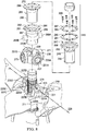
FIG. 4 is an oblique view of a portion of the rotor hub assembly ofFIGS. 1-3 . -
FIG. 5 is an exploded view of a portion of the rotor hub assembly ofFIGS 1-4 . -
FIG. 6 is an oblique view of an elastomeric member of the rotor hub assembly ofFIGS. 1-5 . -
FIG. 7 is an oblique view of another rotor hub assembly according to this disclosure. -
FIG. 8 is an exploded view of the rotor hub assembly ofFIG. 7 . -
FIG. 9 is an oblique view of a portion of the rotor mast assembly ofFIGS. 7 and8 . - In this disclosure, reference may be made to the spatial relationships between various components and to the spatial orientation of various aspects of components as the devices are depicted in the attached drawings. However, as will be recognized by those skilled in the art after a complete reading of this disclosure, the devices, members, apparatuses, etc. described herein may be positioned in any desired orientation. Thus, the use of terms such as "above," "below," "upper," "lower," or other like terms to describe a spatial relationship between various components or to describe the spatial orientation of aspects of such components should be understood to describe a relative relationship between the components or a spatial orientation of aspects of such components, respectively, as the device described herein may be oriented in any desired direction.
- The solution presented in this disclosure solves the dilemma of 2/rev vibrations in a gimbaled rotor hub by using a rotor hub assembly with a universal joint and an elastomeric mast joint that may be used to tune the natural frequency away from the 2/rev torsional oscillatory drive forces that are generated by the universal joint. This simplified solution will not only save money, but will also save a substantial amount of weight. While the disclosed rotor hub assembly may be used on any rotorcraft, it is particularly well-suited for use on tiltrotor aircraft.
- As shown in
FIGS. 1 and2 , arotor hub assembly 101 is illustrated.Rotor hub assembly 101 is show optionally disposed within a shroud 103 (shown cut-away).Rotor hub assembly 101 is attached to arotor mast 105 to facilitate the transmission of torque from a powerplant to cause the rotation ofblades 107, thereby generating lift and/or thrust.Rotor hub assembly 101 includes auniversal joint 109 attached to ayoke 111.Universal joint 109permits yoke 111 to rotate about an axis of rotation that is free to move relative to the axis of rotation ofrotor mast 105. Yoke 111 includes fourarms 113 extending therefrom to supportblades 107. As shown,arms 113 may include structure to facilitate the attachment of outboard shear/CF bearings 115 as well asinboard pitch bearings 117. -
FIG. 3 illustratesuniversal joint 109 attached torotor mast 105.Universal joint 109 includes a pair ofyoke brackets yoke brackets yoke brackets yoke bracket base yoke 111.Bases openings yoke brackets bases tabs Tabs openings longitudinal axis 129. Each opening 127A, 127B is configured to receive ahinge pin 131A, 131B and a radial bearing 133A, 133B therein. Hingepins 131A, 131B connectyoke brackets cross member 135 via afirst aperture 137 and asecond aperture 139.First aperture 137 andsecond aperture 139 are also coaxial about centrallongitudinal axis 129. Hingepin 131A extends from opening 127A tofirst aperture 137.First aperture 137 may also include a radial bearing 141 configured to facilitate rotation ofhinge pin 131A therein. Similarly,second aperture 139 may include a radial bearing 143 configured to facilitate rotation of hinge pin 131B therein.Universal joint 109 also includes adrive member 145 configured to transfer torque fromrotor mast 105 to crossmember 135. - Referring to
FIGS. 4 and5 ,drive member 145 is shown in more detail.Drive member 145 includes aninner member 147 having aninner surface 149 configured to engagerotor mast 105. This engagement may be accomplished via the use ofsplines 151 oninner surface 149 andcomplimentary splines 153 onrotor mast 105.Inner member 147 has anouter surface 155 that includes a plurality ofprojections 157 extending therefrom.Drive member 145 also includes anouter member 159 surroundinginner member 147.Outer member 159 includes aninner surface 161 that includes a plurality ofprojections 163 extending therefrom, such thatprojections 163 interlace withprojections 157. A plurality ofelastomeric members 165 are disposed between the interlacedprojections Outer member 159 also includes anouter surface 167 with a pair oftrunnions FIG. 3 ,trunnion 169A extends into athird aperture 171 ofcross member 135, andtrunnion 169B extends in afourth aperture 173 ofcross member 135, whereinthird aperture 171 andfourth aperture 173 are coaxial about centrallongitudinal axis 175. Accordingly,cross member 135 is pivotally attached to drivemember 145 about centrallongitudinal axis 175. - As shown in
FIG. 6 ,elastomeric members 165 may be made of alternating layers ofelastomeric material 177 andrigid material 179.Elastomeric material 177 may comprise natural or synthetic rubber, or any other elastomeric material suitable for such application.Rigid material 179 may be formed of metal, plastic, composite, or any other material suitable for such application. - In operation, torque is transmitted through
rotor mast 105 to drivemember 145,cross member 135, yoke brackets119A, 119B, andyoke 111, which rotatesblades 107. Whenyoke 111 rotates about an axis that is not coincident with the axis of rotation ofrotor mast 105, 2/rev oscillations are generated byuniversal joint 109. These 2/rev oscillations are attenuated by tuningelastomeric members 165 to absorb them in compression, rather than allowing the oscillations to be transmitted downrotor mast 105 to the drivetrain. - Referring to
FIGS. 7 and8 , arotor hub assembly 201 is illustrated.Rotor hub assembly 201 is attached to arotor mast 205 to facilitate the transmission of torque from a powerplant to cause the rotation of blades (not shown), thereby generating lift and/or thrust.Rotor hub assembly 201 includes auniversal joint 209 attached to ayoke 211. Universal joint 209permits yoke 211 to rotate about an axis of rotation that is free to move relative to the axis of rotation ofrotor mast 205.Yoke 211 includes threearms 213 extending therefrom to support the blades. Universal joint 209 includes ayoke bracket 219.Yoke bracket 219 includes abase 221 for providing a stable connection withyoke 211.Base 221 includes a plurality ofopenings 223 extending therethrough to accept hardware for attachingyoke bracket 219 toyoke 211. Extending frombase 221 aretabs Tabs openings Openings longitudinal axis 229.Openings hinge pin 231A and aradial bearing 233A therein. Andopenings hinge pin 231B and aradial bearing 233B therein. Hinge pins 231A, 231B connectyoke bracket 219 to across member 235 via afirst aperture 237 and asecond aperture 239.First aperture 237 andsecond aperture 239 are also coaxial about centrallongitudinal axis 229.Hinge pin 231A extends from opening 227A throughfirst aperture 237 to opening 227B.Hinge pin 231B extends from opening 227C throughsecond aperture 239 toopening 227D. Universal joint 209 also includes adrive member 245 configured to transfer torque fromrotor mast 205 to crossmember 235. - Referring to
FIGS. 8 and9 ,drive member 245 includes aninner member 247 having aninner surface 249 configured to engagerotor mast 205.Inner member 247 has a substantially cylindricalouter surface 255.Inner member 247 also includes aflange 256 extending radially therefrom.Flange 256 defines a plurality ofopenings 258 extending therethrough.Drive member 245 also includes anouter member 259 surroundinginner member 247.Outer member 259 includes a substantially cylindricalinner surface 261.Outer member 259 also includes aflange 262 extending radially therefrom.Flange 262 includes a plurality ofopenings 264 extending therethrough. Anelastomeric member 265 is located betweeninner member 247 andouter member 259. Theelastomeric member 265 includes a hollowcylindrical portion 266 configured to fit between substantially cylindricalouter surface 255 ofinner member 247 and substantially cylindricalinner surface 261 ofouter member 259.Elastomeric member 265 includes aflange 268 extending therefrom.Flange 268 includes a plurality ofopenings 270 extending therethrough.Outer member 259 also includes anouter surface 267 with a pair oftrunnions Trunnion 269A extends into athird aperture 271 ofcross member 235, andtrunnion 269B extends in afourth aperture 273 ofcross member 235, whereinthird aperture 271 andfourth aperture 273 are coaxial about a centrallongitudinal axis 275. Accordingly,cross member 235 is pivotally attached to drivemember 245 about centrallongitudinal axis 275. -
Drive member 245 may also include anelastomeric ring 281 and aninelastic ring 283.Elastomeric ring 281 andinelastic ring 283 each include a plurality of openings extending therethrough, 285 and 287, respectively. When assembled,flange 262 ofouter member 259 has flange 268 ofelastomeric member 265 on top thereof, followed byflange 256 ofinner member 247, thenelastomeric ring 281, and finallyinelastic ring 283 on the top.Flanges openings connection bolts 289 therethrough. - In operation, torque is transmitted through
rotor mast 205,drive member 245,cross member 235,yoke bracket 219, andyoke 211, to rotate the blades. Whenyoke 211 rotates about an axis that is not coincident with the axis of rotation ofrotor mast 205, 2/rev oscillations are generated byuniversal joint 209. These 2/rev oscillations are attenuated by tuningelastomeric member 265 andelastomeric ring 281 to absorb them in shear, rather than allowing the oscillations to be transmitted downrotor mast 205 to the drivetrain. Additionalelastomeric rings 281 andinelastic rings 283 may be added as required. - In the embodiments shown, the drive members and cross members show the masts passing through the centers thereof. It should be understood that the drive member could be mounted to a distal end of the mast. In addition, axis about which the cross member is pivotally attached to the yoke bracket could be above or below the drive member.
- At least one embodiment is disclosed, and variations, combinations, and/or modifications of the embodiment(s) and/or features of the embodiment(s) made by a person having ordinary skill in the art are within the scope of the disclosure. Alternative embodiments that result from combining, integrating, and/or omitting features of the embodiment(s) are also within the scope of the disclosure. Where numerical ranges or limitations are expressly stated, such express ranges or limitations should be understood to include iterative ranges or limitations of like magnitude falling within the expressly stated ranges or limitations (e.g., from about 1 to about 10 includes, 2, 3, 4, etc.; greater than 0.10 includes 0.11, 0.12, 0.13, etc.). For example, whenever a numerical range with a lower limit, Rl, and an upper limit, Ru, is disclosed, any number falling within the range is specifically disclosed. In particular, the following numbers within the range are specifically disclosed: R=R1+k * (Ru-Rl), wherein k is a variable ranging from 1 percent to 100 percent with a 1 percent increment, i.e., k is 1 percent, 2 percent, 3 percent, 4 percent, 5 percent,...50 percent, 51 percent, 52 percent,..., 95 percent, 96 percent, 95 percent, 98 percent, 99 percent, or 100 percent. Moreover, any numerical range defined by two R numbers as defined in the above is also specifically disclosed. Use of the term "optionally" with respect to any element of a claim means that the element is required, or alternatively, the element is not required, both alternatives being within the scope of the claim. Use of broader terms such as comprises, includes, and having should be understood to provide support for narrower terms such as consisting of, consisting essentially of, and comprised substantially of. Accordingly, the scope of protection is not limited by the description set out above but is defined by the claims that follow, that scope including all equivalents of the subject matter of the claims. Each and every claim is incorporated as further disclosure into the specification and the claims are embodiment(s) of the present invention. Also, the phrases "at least one of A, B, and C" and "A and/or B and/or C" should each be interpreted to include only A, only B, only C, or any combination of A, B, and C.
Claims (15)
- A rotor hub assembly, comprising:a yoke having at least two arms extending therefrom;a yoke bracket having a base attached to the yoke, the yoke bracket including a tab extending from the base, the tab defining an opening extending therethrough;a cross member defining a first aperture and a second aperture coaxially aligned with each other, and further defining a third aperture, the first and second apertures being orthogonal to the third aperture;a drive member, comprising:an inner member having an outer surface, the outer surface including a first plurality of projections extending therefrom;an outer member having an outer surface and an opposite inner surface, the inner surface including a second plurality of projections extending therefrom, the outer member being configured to surround the inner member such that the second plurality of projections interlace with the first plurality of projections, the outer member also including a pair of trunnions extending from the outer surface thereof, the trunnions being positioned coaxially within the first and second apertures of the cross member; anda plurality of elastomeric members, each elastomeric member being configured to fit between one of the first projections and one of the second projections; anda hinge pin, the hinge pin being positioned coaxially within the opening of the tab of the yoke bracket and the second aperture of the cross member.
- The rotor hub assembly of claim 1, further comprising:a second yoke bracket having a second base attached to the yoke, the second yoke bracket including a second tab extending therefrom, the second tab defining a second opening extending therethrough; anda second hinge pin, the second hinge pin being positioned coaxially within the second opening of the second tab and a fourth aperture of the cross member.
- The rotor hub assembly of claim 2, wherein each of the plurality of elastomeric members have alternating layers of elastomeric and inelastic material.
- The rotor hub assembly of claim 3, wherein the inner member includes a splined inner surface configured to engage a mast.
- A rotor hub assembly, comprising:a yoke having at least two arms extending therefrom;a yoke bracket attached to the yoke;a cross member defining a first aperture with a first central longitudinal axis and a second aperture with a second central longitudinal axis, the first central longitudinal axis being orthogonal to the second central longitudinal axis, the cross member being pivotally attached to the yoke bracket about the first central longitudinal axis;a drive member, comprising:an inner member configured to engage a mast;an outer member pivotally attached to the cross member about the second central longitudinal axis; andan elastomeric member disposed between the inner member from the outer member.
- The rotor hub assembly of claim 5, wherein the cross member further includes a third aperture coaxial with the first aperture and a fourth aperture coaxial with the second aperture.
- The rotor hub assembly of claim 4, wherein the third and fourth apertures are coaxial, and a central longitudinal axis of the third and fourth apertures is coplanar with a central longitudinal axis of the first and second apertures; or
the rotor hub assembly of claim 6, wherein the first and second central longitudinal axes are coplanar. - The rotor hub assembly of claim 7, wherein the elastomeric members are configured to attenuate 2/rev vibrations, or
the rotor hub assembly of claim 7, the elastomeric member being configured to attenuate 2/rev vibrations transmitted to the inner member from the outer member. - The rotor hub assembly of claim 8, wherein:(i) the inner member has a substantially cylindrical outer surface, the outer member has a substantially cylindrical inner surface, and the elastomeric member includes a hollow cylindrical portion configured to fit between the substantially cylindrical outer surface of the inner member and the substantially cylindrical inner surface of the outer member, and optionally or preferably,(ii) wherein the inner member and the outer member are connected via a pair of flanges.
- The rotor hub assembly of claim 8 or the rotor hub assembly of claim 9, part (ii), wherein the yoke includes four arms extending therefrom.
- A rotor hub assembly, comprising:a yoke configured to attach blades thereto;a universal joint configured to attach to, and transmit forces between, a mast and the yoke; andan elastomeric member configured to attenuate vibrations being transmitted from the universal joint to the mast.
- The rotor hub assembly of claim 11, wherein the universal joint comprises:a yoke bracket attached to the yoke;a cross member defining a first aperture with a first central longitudinal axis and a second aperture with a second central longitudinal axis, the first central longitudinal axis being orthogonal to the second central longitudinal axis, the cross member being pivotally attached to the yoke bracket about the first central longitudinal axis; anda drive member pivotally attached to the cross member about the second central longitudinal axis.
- The rotor hub assembly of claim 12, the drive member comprising:an inner drive member configured to engage the mast; andan outer drive member, wherein the elastomeric member is disposed at least partially between the inner drive member and the outer drive member.
- The rotor hub assembly of claim 13, wherein the inner member includes an outer surface having a first plurality of projections extending therefrom, the outer member includes an inner surface having a second plurality of projections extending therefrom, the outer member being configured to surround the inner member such that the second plurality of projections interlace with the first plurality of projections.
- The rotor hub assembly of claim 14, wherein the elastomeric member has alternating layers of elastomeric and inelastic material, and optionally or preferably, wherein the elastomeric member is configured to attenuate 2/rev vibrations.
Applications Claiming Priority (1)
| Application Number | Priority Date | Filing Date | Title |
|---|---|---|---|
| US15/658,190 US10766612B2 (en) | 2017-07-24 | 2017-07-24 | Rotor hub assembly with universal joint |
Publications (2)
| Publication Number | Publication Date |
|---|---|
| EP3434588A1 true EP3434588A1 (en) | 2019-01-30 |
| EP3434588B1 EP3434588B1 (en) | 2020-11-18 |
Family
ID=62816451
Family Applications (1)
| Application Number | Title | Priority Date | Filing Date |
|---|---|---|---|
| EP18180551.6A Not-in-force EP3434588B1 (en) | 2017-07-24 | 2018-06-28 | Rotor hub assembly with universal joint |
Country Status (2)
| Country | Link |
|---|---|
| US (2) | US10766612B2 (en) |
| EP (1) | EP3434588B1 (en) |
Families Citing this family (2)
| Publication number | Priority date | Publication date | Assignee | Title |
|---|---|---|---|---|
| US11745853B2 (en) * | 2020-03-17 | 2023-09-05 | Textron Innovations Inc. | Single Hooke's joint with spherical mast attachment |
| US11591079B2 (en) * | 2020-10-27 | 2023-02-28 | Textron Innovations Inc. | Drive tube and swashplate trunnion assembly with cylindrical bearings |
Citations (3)
| Publication number | Priority date | Publication date | Assignee | Title |
|---|---|---|---|---|
| US5215502A (en) * | 1985-11-04 | 1993-06-01 | Bell Helicopter Textron Inc. | Constant velocity elastomeric joint |
| US20150053814A1 (en) * | 2013-08-26 | 2015-02-26 | Bell Helicopter Textron Inc. | Rotor System with Torque-Splitter Assembly |
| US9382001B2 (en) * | 2014-07-23 | 2016-07-05 | Bell Helicopter Textron Inc. | Torque transfer system for a rotorcraft |
Family Cites Families (5)
| Publication number | Priority date | Publication date | Assignee | Title |
|---|---|---|---|---|
| US5074494A (en) * | 1990-10-11 | 1991-12-24 | United Technologies Corporation | Elastomeric swashplate configuration for helicopters |
| US5083725A (en) * | 1990-10-11 | 1992-01-28 | United Technologies Corporation | Elastomeric swashplate configuration for helicopters |
| US8038539B2 (en) * | 2008-01-04 | 2011-10-18 | Bell Helicopter Textron Inc. | Constant-velocity joint with torque-combining differential |
| US7961063B2 (en) | 2008-07-31 | 2011-06-14 | Freescale Semiconductor, Inc. | Balun signal transformer and method of forming |
| US10232932B2 (en) * | 2017-03-22 | 2019-03-19 | Bell Helicopter Textron Inc. | High stiffness hub assembly for proprotor systems |
-
2017
- 2017-07-24 US US15/658,190 patent/US10766612B2/en not_active Expired - Fee Related
-
2018
- 2018-06-28 EP EP18180551.6A patent/EP3434588B1/en not_active Not-in-force
-
2020
- 2020-09-08 US US17/014,897 patent/US11396371B2/en active Active
Patent Citations (3)
| Publication number | Priority date | Publication date | Assignee | Title |
|---|---|---|---|---|
| US5215502A (en) * | 1985-11-04 | 1993-06-01 | Bell Helicopter Textron Inc. | Constant velocity elastomeric joint |
| US20150053814A1 (en) * | 2013-08-26 | 2015-02-26 | Bell Helicopter Textron Inc. | Rotor System with Torque-Splitter Assembly |
| US9382001B2 (en) * | 2014-07-23 | 2016-07-05 | Bell Helicopter Textron Inc. | Torque transfer system for a rotorcraft |
Also Published As
| Publication number | Publication date |
|---|---|
| EP3434588B1 (en) | 2020-11-18 |
| US10766612B2 (en) | 2020-09-08 |
| US11396371B2 (en) | 2022-07-26 |
| US20200407054A1 (en) | 2020-12-31 |
| US20190023386A1 (en) | 2019-01-24 |
Similar Documents
| Publication | Publication Date | Title |
|---|---|---|
| US3967918A (en) | Rotor for rotating wing type aircraft | |
| US8430757B2 (en) | Constant-velocity joint with torque-combining differential | |
| US4886419A (en) | Elastomeric bearing for helicopter rotor having lead-lag damping | |
| US8622703B2 (en) | Blade provided with a drag damper, and a rotor provided with such a blade | |
| US11040771B2 (en) | Rotor hub | |
| CA2805167C (en) | Aircraft rotor with discrete flap hinge | |
| EP0449531B1 (en) | Rotors | |
| KR20150000411A (en) | Rotor system of a rotary wing aircraft | |
| US11396371B2 (en) | Rotor hub assembly with universal joint | |
| US10752346B2 (en) | Rotor assembly with composite static mast | |
| JP4112870B2 (en) | Aircraft constant speed transmission rotor | |
| EP2894095B1 (en) | Constant velocity drive for tilt rotor assembly | |
| US20230213059A1 (en) | Journal bearings | |
| US20180327086A1 (en) | Gimbaled Rotor Hub Assembly with Spherical Bearing | |
| US10457388B2 (en) | Rotor assembly with high lock-number blades | |
| EP3216695B1 (en) | Rotor assembly with high lock-number blades | |
| EP3459847A1 (en) | Rotor hub with blade-to-blade dampers and axisymmetric elastomeric spherical bearings | |
| CN115924071A (en) | Tilt rotor aircraft hub system | |
| US20230234701A1 (en) | Rotor for an aircraft capable of hovering | |
| RU2729900C9 (en) | Drive system of coaxial rotors of helicopter with support mast | |
| CA2995295C (en) | Rotor assembly with high lock-number blades |
Legal Events
| Date | Code | Title | Description |
|---|---|---|---|
| STAA | Information on the status of an ep patent application or granted ep patent |
Free format text: STATUS: EXAMINATION IS IN PROGRESS |
|
| PUAI | Public reference made under article 153(3) epc to a published international application that has entered the european phase |
Free format text: ORIGINAL CODE: 0009012 |
|
| 17P | Request for examination filed |
Effective date: 20180628 |
|
| AK | Designated contracting states |
Kind code of ref document: A1 Designated state(s): AL AT BE BG CH CY CZ DE DK EE ES FI FR GB GR HR HU IE IS IT LI LT LU LV MC MK MT NL NO PL PT RO RS SE SI SK SM TR |
|
| AX | Request for extension of the european patent |
Extension state: BA ME |
|
| GRAP | Despatch of communication of intention to grant a patent |
Free format text: ORIGINAL CODE: EPIDOSNIGR1 |
|
| GRAJ | Information related to disapproval of communication of intention to grant by the applicant or resumption of examination proceedings by the epo deleted |
Free format text: ORIGINAL CODE: EPIDOSDIGR1 |
|
| GRAP | Despatch of communication of intention to grant a patent |
Free format text: ORIGINAL CODE: EPIDOSNIGR1 |
|
| GRAP | Despatch of communication of intention to grant a patent |
Free format text: ORIGINAL CODE: EPIDOSNIGR1 |
|
| STAA | Information on the status of an ep patent application or granted ep patent |
Free format text: STATUS: GRANT OF PATENT IS INTENDED |
|
| INTG | Intention to grant announced |
Effective date: 20200605 |
|
| RIN1 | Information on inventor provided before grant (corrected) |
Inventor name: RAUBER, RICHARD E. Inventor name: STAMPS, FRANK BRADLEY |
|
| INTG | Intention to grant announced |
Effective date: 20200610 |
|
| GRAS | Grant fee paid |
Free format text: ORIGINAL CODE: EPIDOSNIGR3 |
|
| GRAA | (expected) grant |
Free format text: ORIGINAL CODE: 0009210 |
|
| STAA | Information on the status of an ep patent application or granted ep patent |
Free format text: STATUS: THE PATENT HAS BEEN GRANTED |
|
| AK | Designated contracting states |
Kind code of ref document: B1 Designated state(s): AL AT BE BG CH CY CZ DE DK EE ES FI FR GB GR HR HU IE IS IT LI LT LU LV MC MK MT NL NO PL PT RO RS SE SI SK SM TR |
|
| REG | Reference to a national code |
Ref country code: GB Ref legal event code: FG4D |
|
| REG | Reference to a national code |
Ref country code: CH Ref legal event code: EP |
|
| REG | Reference to a national code |
Ref country code: IE Ref legal event code: FG4D |
|
| REG | Reference to a national code |
Ref country code: DE Ref legal event code: R096 Ref document number: 602018009770 Country of ref document: DE |
|
| REG | Reference to a national code |
Ref country code: AT Ref legal event code: REF Ref document number: 1335493 Country of ref document: AT Kind code of ref document: T Effective date: 20201215 |
|
| REG | Reference to a national code |
Ref country code: AT Ref legal event code: MK05 Ref document number: 1335493 Country of ref document: AT Kind code of ref document: T Effective date: 20201118 |
|
| REG | Reference to a national code |
Ref country code: NL Ref legal event code: MP Effective date: 20201118 |
|
| PG25 | Lapsed in a contracting state [announced via postgrant information from national office to epo] |
Ref country code: GR Free format text: LAPSE BECAUSE OF FAILURE TO SUBMIT A TRANSLATION OF THE DESCRIPTION OR TO PAY THE FEE WITHIN THE PRESCRIBED TIME-LIMIT Effective date: 20210219 Ref country code: NO Free format text: LAPSE BECAUSE OF FAILURE TO SUBMIT A TRANSLATION OF THE DESCRIPTION OR TO PAY THE FEE WITHIN THE PRESCRIBED TIME-LIMIT Effective date: 20210218 Ref country code: FI Free format text: LAPSE BECAUSE OF FAILURE TO SUBMIT A TRANSLATION OF THE DESCRIPTION OR TO PAY THE FEE WITHIN THE PRESCRIBED TIME-LIMIT Effective date: 20201118 Ref country code: PT Free format text: LAPSE BECAUSE OF FAILURE TO SUBMIT A TRANSLATION OF THE DESCRIPTION OR TO PAY THE FEE WITHIN THE PRESCRIBED TIME-LIMIT Effective date: 20210318 Ref country code: RS Free format text: LAPSE BECAUSE OF FAILURE TO SUBMIT A TRANSLATION OF THE DESCRIPTION OR TO PAY THE FEE WITHIN THE PRESCRIBED TIME-LIMIT Effective date: 20201118 |
|
| PG25 | Lapsed in a contracting state [announced via postgrant information from national office to epo] |
Ref country code: BG Free format text: LAPSE BECAUSE OF FAILURE TO SUBMIT A TRANSLATION OF THE DESCRIPTION OR TO PAY THE FEE WITHIN THE PRESCRIBED TIME-LIMIT Effective date: 20210218 Ref country code: PL Free format text: LAPSE BECAUSE OF FAILURE TO SUBMIT A TRANSLATION OF THE DESCRIPTION OR TO PAY THE FEE WITHIN THE PRESCRIBED TIME-LIMIT Effective date: 20201118 Ref country code: LV Free format text: LAPSE BECAUSE OF FAILURE TO SUBMIT A TRANSLATION OF THE DESCRIPTION OR TO PAY THE FEE WITHIN THE PRESCRIBED TIME-LIMIT Effective date: 20201118 Ref country code: IS Free format text: LAPSE BECAUSE OF FAILURE TO SUBMIT A TRANSLATION OF THE DESCRIPTION OR TO PAY THE FEE WITHIN THE PRESCRIBED TIME-LIMIT Effective date: 20210318 Ref country code: SE Free format text: LAPSE BECAUSE OF FAILURE TO SUBMIT A TRANSLATION OF THE DESCRIPTION OR TO PAY THE FEE WITHIN THE PRESCRIBED TIME-LIMIT Effective date: 20201118 Ref country code: AT Free format text: LAPSE BECAUSE OF FAILURE TO SUBMIT A TRANSLATION OF THE DESCRIPTION OR TO PAY THE FEE WITHIN THE PRESCRIBED TIME-LIMIT Effective date: 20201118 |
|
| REG | Reference to a national code |
Ref country code: LT Ref legal event code: MG9D |
|
| PG25 | Lapsed in a contracting state [announced via postgrant information from national office to epo] |
Ref country code: HR Free format text: LAPSE BECAUSE OF FAILURE TO SUBMIT A TRANSLATION OF THE DESCRIPTION OR TO PAY THE FEE WITHIN THE PRESCRIBED TIME-LIMIT Effective date: 20201118 |
|
| PG25 | Lapsed in a contracting state [announced via postgrant information from national office to epo] |
Ref country code: RO Free format text: LAPSE BECAUSE OF FAILURE TO SUBMIT A TRANSLATION OF THE DESCRIPTION OR TO PAY THE FEE WITHIN THE PRESCRIBED TIME-LIMIT Effective date: 20201118 Ref country code: SK Free format text: LAPSE BECAUSE OF FAILURE TO SUBMIT A TRANSLATION OF THE DESCRIPTION OR TO PAY THE FEE WITHIN THE PRESCRIBED TIME-LIMIT Effective date: 20201118 Ref country code: LT Free format text: LAPSE BECAUSE OF FAILURE TO SUBMIT A TRANSLATION OF THE DESCRIPTION OR TO PAY THE FEE WITHIN THE PRESCRIBED TIME-LIMIT Effective date: 20201118 Ref country code: SM Free format text: LAPSE BECAUSE OF FAILURE TO SUBMIT A TRANSLATION OF THE DESCRIPTION OR TO PAY THE FEE WITHIN THE PRESCRIBED TIME-LIMIT Effective date: 20201118 Ref country code: EE Free format text: LAPSE BECAUSE OF FAILURE TO SUBMIT A TRANSLATION OF THE DESCRIPTION OR TO PAY THE FEE WITHIN THE PRESCRIBED TIME-LIMIT Effective date: 20201118 Ref country code: CZ Free format text: LAPSE BECAUSE OF FAILURE TO SUBMIT A TRANSLATION OF THE DESCRIPTION OR TO PAY THE FEE WITHIN THE PRESCRIBED TIME-LIMIT Effective date: 20201118 |
|
| REG | Reference to a national code |
Ref country code: DE Ref legal event code: R097 Ref document number: 602018009770 Country of ref document: DE |
|
| PG25 | Lapsed in a contracting state [announced via postgrant information from national office to epo] |
Ref country code: DK Free format text: LAPSE BECAUSE OF FAILURE TO SUBMIT A TRANSLATION OF THE DESCRIPTION OR TO PAY THE FEE WITHIN THE PRESCRIBED TIME-LIMIT Effective date: 20201118 |
|
| PLBE | No opposition filed within time limit |
Free format text: ORIGINAL CODE: 0009261 |
|
| STAA | Information on the status of an ep patent application or granted ep patent |
Free format text: STATUS: NO OPPOSITION FILED WITHIN TIME LIMIT |
|
| 26N | No opposition filed |
Effective date: 20210819 |
|
| PG25 | Lapsed in a contracting state [announced via postgrant information from national office to epo] |
Ref country code: NL Free format text: LAPSE BECAUSE OF FAILURE TO SUBMIT A TRANSLATION OF THE DESCRIPTION OR TO PAY THE FEE WITHIN THE PRESCRIBED TIME-LIMIT Effective date: 20201118 Ref country code: AL Free format text: LAPSE BECAUSE OF FAILURE TO SUBMIT A TRANSLATION OF THE DESCRIPTION OR TO PAY THE FEE WITHIN THE PRESCRIBED TIME-LIMIT Effective date: 20201118 |
|
| PG25 | Lapsed in a contracting state [announced via postgrant information from national office to epo] |
Ref country code: SI Free format text: LAPSE BECAUSE OF FAILURE TO SUBMIT A TRANSLATION OF THE DESCRIPTION OR TO PAY THE FEE WITHIN THE PRESCRIBED TIME-LIMIT Effective date: 20201118 |
|
| PG25 | Lapsed in a contracting state [announced via postgrant information from national office to epo] |
Ref country code: ES Free format text: LAPSE BECAUSE OF FAILURE TO SUBMIT A TRANSLATION OF THE DESCRIPTION OR TO PAY THE FEE WITHIN THE PRESCRIBED TIME-LIMIT Effective date: 20201118 Ref country code: MC Free format text: LAPSE BECAUSE OF FAILURE TO SUBMIT A TRANSLATION OF THE DESCRIPTION OR TO PAY THE FEE WITHIN THE PRESCRIBED TIME-LIMIT Effective date: 20201118 |
|
| REG | Reference to a national code |
Ref country code: CH Ref legal event code: PL |
|
| REG | Reference to a national code |
Ref country code: BE Ref legal event code: MM Effective date: 20210630 |
|
| PG25 | Lapsed in a contracting state [announced via postgrant information from national office to epo] |
Ref country code: LU Free format text: LAPSE BECAUSE OF NON-PAYMENT OF DUE FEES Effective date: 20210628 |
|
| PG25 | Lapsed in a contracting state [announced via postgrant information from national office to epo] |
Ref country code: LI Free format text: LAPSE BECAUSE OF NON-PAYMENT OF DUE FEES Effective date: 20210630 Ref country code: IE Free format text: LAPSE BECAUSE OF NON-PAYMENT OF DUE FEES Effective date: 20210628 Ref country code: CH Free format text: LAPSE BECAUSE OF NON-PAYMENT OF DUE FEES Effective date: 20210630 |
|
| PG25 | Lapsed in a contracting state [announced via postgrant information from national office to epo] |
Ref country code: IS Free format text: LAPSE BECAUSE OF FAILURE TO SUBMIT A TRANSLATION OF THE DESCRIPTION OR TO PAY THE FEE WITHIN THE PRESCRIBED TIME-LIMIT Effective date: 20210318 |
|
| PG25 | Lapsed in a contracting state [announced via postgrant information from national office to epo] |
Ref country code: BE Free format text: LAPSE BECAUSE OF NON-PAYMENT OF DUE FEES Effective date: 20210630 |
|
| PG25 | Lapsed in a contracting state [announced via postgrant information from national office to epo] |
Ref country code: CY Free format text: LAPSE BECAUSE OF FAILURE TO SUBMIT A TRANSLATION OF THE DESCRIPTION OR TO PAY THE FEE WITHIN THE PRESCRIBED TIME-LIMIT Effective date: 20201118 |
|
| P01 | Opt-out of the competence of the unified patent court (upc) registered |
Effective date: 20230602 |
|
| PG25 | Lapsed in a contracting state [announced via postgrant information from national office to epo] |
Ref country code: HU Free format text: LAPSE BECAUSE OF FAILURE TO SUBMIT A TRANSLATION OF THE DESCRIPTION OR TO PAY THE FEE WITHIN THE PRESCRIBED TIME-LIMIT; INVALID AB INITIO Effective date: 20180628 |
|
| PGFP | Annual fee paid to national office [announced via postgrant information from national office to epo] |
Ref country code: FR Payment date: 20230626 Year of fee payment: 6 Ref country code: DE Payment date: 20230626 Year of fee payment: 6 |
|
| PGFP | Annual fee paid to national office [announced via postgrant information from national office to epo] |
Ref country code: IT Payment date: 20230620 Year of fee payment: 6 Ref country code: GB Payment date: 20230627 Year of fee payment: 6 |
|
| PG25 | Lapsed in a contracting state [announced via postgrant information from national office to epo] |
Ref country code: MK Free format text: LAPSE BECAUSE OF FAILURE TO SUBMIT A TRANSLATION OF THE DESCRIPTION OR TO PAY THE FEE WITHIN THE PRESCRIBED TIME-LIMIT Effective date: 20201118 |
|
| PG25 | Lapsed in a contracting state [announced via postgrant information from national office to epo] |
Ref country code: TR Free format text: LAPSE BECAUSE OF FAILURE TO SUBMIT A TRANSLATION OF THE DESCRIPTION OR TO PAY THE FEE WITHIN THE PRESCRIBED TIME-LIMIT Effective date: 20201118 |
|
| PG25 | Lapsed in a contracting state [announced via postgrant information from national office to epo] |
Ref country code: MT Free format text: LAPSE BECAUSE OF FAILURE TO SUBMIT A TRANSLATION OF THE DESCRIPTION OR TO PAY THE FEE WITHIN THE PRESCRIBED TIME-LIMIT Effective date: 20201118 |
|
| REG | Reference to a national code |
Ref country code: DE Ref legal event code: R119 Ref document number: 602018009770 Country of ref document: DE |
|
| GBPC | Gb: european patent ceased through non-payment of renewal fee |
Effective date: 20240628 |
|
| PG25 | Lapsed in a contracting state [announced via postgrant information from national office to epo] |
Ref country code: DE Free format text: LAPSE BECAUSE OF NON-PAYMENT OF DUE FEES Effective date: 20250101 |
|
| PG25 | Lapsed in a contracting state [announced via postgrant information from national office to epo] |
Ref country code: FR Free format text: LAPSE BECAUSE OF NON-PAYMENT OF DUE FEES Effective date: 20240630 |
|
| PG25 | Lapsed in a contracting state [announced via postgrant information from national office to epo] |
Ref country code: IT Free format text: LAPSE BECAUSE OF NON-PAYMENT OF DUE FEES Effective date: 20240628 Ref country code: GB Free format text: LAPSE BECAUSE OF NON-PAYMENT OF DUE FEES Effective date: 20240628 |