EP3434505B1 - Bogie axle device balance system and bogie axle device - Google Patents
Bogie axle device balance system and bogie axle device Download PDFInfo
- Publication number
- EP3434505B1 EP3434505B1 EP16895437.8A EP16895437A EP3434505B1 EP 3434505 B1 EP3434505 B1 EP 3434505B1 EP 16895437 A EP16895437 A EP 16895437A EP 3434505 B1 EP3434505 B1 EP 3434505B1
- Authority
- EP
- European Patent Office
- Prior art keywords
- gear
- swing
- driving
- force
- driving unit
- Prior art date
- Legal status (The legal status is an assumption and is not a legal conclusion. Google has not performed a legal analysis and makes no representation as to the accuracy of the status listed.)
- Active
Links
Images






Classifications
-
- B—PERFORMING OPERATIONS; TRANSPORTING
- B60—VEHICLES IN GENERAL
- B60K—ARRANGEMENT OR MOUNTING OF PROPULSION UNITS OR OF TRANSMISSIONS IN VEHICLES; ARRANGEMENT OR MOUNTING OF PLURAL DIVERSE PRIME-MOVERS IN VEHICLES; AUXILIARY DRIVES FOR VEHICLES; INSTRUMENTATION OR DASHBOARDS FOR VEHICLES; ARRANGEMENTS IN CONNECTION WITH COOLING, AIR INTAKE, GAS EXHAUST OR FUEL SUPPLY OF PROPULSION UNITS IN VEHICLES
- B60K17/00—Arrangement or mounting of transmissions in vehicles
- B60K17/32—Arrangement or mounting of transmissions in vehicles the ultimate propulsive elements, e.g. ground wheels, being rockable about a horizontal pivot
-
- B—PERFORMING OPERATIONS; TRANSPORTING
- B60—VEHICLES IN GENERAL
- B60B—VEHICLE WHEELS; CASTORS; AXLES FOR WHEELS OR CASTORS; INCREASING WHEEL ADHESION
- B60B35/00—Axle units; Parts thereof ; Arrangements for lubrication of axles
- B60B35/12—Torque-transmitting axles
- B60B35/121—Power-transmission from drive shaft to hub
- B60B35/122—Power-transmission from drive shaft to hub using gearings
- B60B35/125—Power-transmission from drive shaft to hub using gearings of the planetary type
-
- B—PERFORMING OPERATIONS; TRANSPORTING
- B60—VEHICLES IN GENERAL
- B60K—ARRANGEMENT OR MOUNTING OF PROPULSION UNITS OR OF TRANSMISSIONS IN VEHICLES; ARRANGEMENT OR MOUNTING OF PLURAL DIVERSE PRIME-MOVERS IN VEHICLES; AUXILIARY DRIVES FOR VEHICLES; INSTRUMENTATION OR DASHBOARDS FOR VEHICLES; ARRANGEMENTS IN CONNECTION WITH COOLING, AIR INTAKE, GAS EXHAUST OR FUEL SUPPLY OF PROPULSION UNITS IN VEHICLES
- B60K17/00—Arrangement or mounting of transmissions in vehicles
- B60K17/36—Arrangement or mounting of transmissions in vehicles for driving tandem wheels
-
- B—PERFORMING OPERATIONS; TRANSPORTING
- B60—VEHICLES IN GENERAL
- B60Y—INDEXING SCHEME RELATING TO ASPECTS CROSS-CUTTING VEHICLE TECHNOLOGY
- B60Y2200/00—Type of vehicle
- B60Y2200/10—Road Vehicles
- B60Y2200/14—Trucks; Load vehicles, Busses
-
- B—PERFORMING OPERATIONS; TRANSPORTING
- B60—VEHICLES IN GENERAL
- B60Y—INDEXING SCHEME RELATING TO ASPECTS CROSS-CUTTING VEHICLE TECHNOLOGY
- B60Y2200/00—Type of vehicle
- B60Y2200/10—Road Vehicles
- B60Y2200/14—Trucks; Load vehicles, Busses
- B60Y2200/142—Heavy duty trucks
- B60Y2200/1422—Multi-axle trucks
-
- B—PERFORMING OPERATIONS; TRANSPORTING
- B60—VEHICLES IN GENERAL
- B60Y—INDEXING SCHEME RELATING TO ASPECTS CROSS-CUTTING VEHICLE TECHNOLOGY
- B60Y2200/00—Type of vehicle
- B60Y2200/20—Off-Road Vehicles
- B60Y2200/22—Agricultural vehicles
-
- B—PERFORMING OPERATIONS; TRANSPORTING
- B60—VEHICLES IN GENERAL
- B60Y—INDEXING SCHEME RELATING TO ASPECTS CROSS-CUTTING VEHICLE TECHNOLOGY
- B60Y2200/00—Type of vehicle
- B60Y2200/20—Off-Road Vehicles
- B60Y2200/22—Agricultural vehicles
- B60Y2200/222—Harvesters
-
- B—PERFORMING OPERATIONS; TRANSPORTING
- B60—VEHICLES IN GENERAL
- B60Y—INDEXING SCHEME RELATING TO ASPECTS CROSS-CUTTING VEHICLE TECHNOLOGY
- B60Y2200/00—Type of vehicle
- B60Y2200/40—Special vehicles
- B60Y2200/41—Construction vehicles, e.g. graders, excavators
-
- B—PERFORMING OPERATIONS; TRANSPORTING
- B60—VEHICLES IN GENERAL
- B60Y—INDEXING SCHEME RELATING TO ASPECTS CROSS-CUTTING VEHICLE TECHNOLOGY
- B60Y2200/00—Type of vehicle
- B60Y2200/40—Special vehicles
- B60Y2200/41—Construction vehicles, e.g. graders, excavators
- B60Y2200/411—Bulldozers, Graders
Definitions
- the present invention relates to a balance system which is capable of, in a bogie axle device supporting two axles arranged in the front and rear directions of a vehicle such that the two axles swing freely, suppressing a swing of a swing housing supporting the two axles, and a bogie axle device provided with the balance system.
- a forwarder 82 which loads short trunk materials subjected to crosscutting onto a cargo bed 81 by a grapple crane 80 and transports the trunk materials.
- Some harvesters and forwarders require higher running performance on hilly ground.
- the forwarder 82 is also provided with a bogie axle device 84, the bogie axle device 84 supporting two axles 83F and 83R arranged in the front and rear directions of a vehicle such that the two axles swing freely relative to the vehicle.
- the bogie axle device 84 includes a driving unit (not shown) fixed to a chassis 82a (see Fig. 10 ) of the vehicle, and a pair of left and right axle units 85 swinging freely relative to the driving unit.
- the driving unit transmits a driving force outputted from an engine of the vehicle to the left and right axle units 85.
- the pair of left and right axle units 85 each include: a swing housing 86 supported by the driving unit such that it swings freely relative to the driving unit; two axles 83F and 83R supported so as to rotate freely by the swing housing 86; and a driving-force transmitting mechanism 87 which transmits a driving force inputted by the driving unit to the two axles 83F and 83R.
- the driving-force transmitting mechanism 87 includes an input gear 87a for inputting the driving force of the driving unit therein, and a plurality of gears for transmitting the rotation of the input gear 87a to the axles 83F and 83R.
- the ratio of the front-wheel load to the rear-wheel load is 50 % : 50 %.
- the swinging torque Ts on the swing housing 86 generates upward and downward reaction forces F1 and F2 on the axles 83F and 83R respectively.
- the ratio of the front-wheel load to the rear-wheel load is, for example, 19.3 % : 80.7 %.
- the lost load balance between the front wheel and the rear wheel worsens when the vehicle is running on a slope.
- the ratio of the front-wheel load to the rear-wheel load is, for example, 12.3 % : 87.7%. Consequently, the reaction forces F1 and F2 generated by the swinging torque Ts may cause the bogie axle device 84 to lose the load balance largely between the front wheel and the rear wheel, thereby inverting the swing housing 86. Further, the load on the rear-wheel axle 83R becomes heavy, thereby causing some concern about the strength thereof.
- the reaction forces F1 and F2 for the swinging torque Ts are calculated by the following numerical formulas.
- a conventional bogie axle device is provided with balance systems.
- the balance system of EP0909671 includes two planetary gear mechanisms: a first-step planetary gear mechanism and a second-step planetary gear mechanism.
- a carrier output of the first-step planetary gear mechanism is inputted in a driving-force transmitting mechanism, and an output from a ring gear of the first-step planetary gear mechanism is inputted in a second-step planetary gear mechanism.
- a ring gear is fixed to a swing housing, and from the ring gear, a swing suppressing torque Tb in the direction opposite to the swinging torque Ts is given to the swing housing, thereby suppressing a swing of the swing housing.
- the driving force inputted from a driving unit is separated into a driving force inputted in the driving-force transmitting mechanism by the first-step planetary gear mechanism and a reaction force for suppressing a swing of the swing housing. Then, the second-step planetary gear mechanism amplifies the reaction force.
- the balance system of EP0 520 389 A2 includes two planetary gear mechanisms, each planetary gear group thereof being coaxially held by a shared carrier.
- a ring gear of a first-step planetary gear mechanism is fixed to the inside of a revolving bearing, the revolving bearing supporting a swing housing so that it can swing freely.
- a ring gear of the second-step planetary gear mechanism is fixed to the swing housing, and a reaction force inputted from the second-step planetary gear mechanism works on the swing housing.
- the swing suppressing torque Tb in the direction opposite to the swinging torque Ts is given to the swing housing, thereby suppressing a swing of the swing housing.
- the first-step planetary gear mechanism amplifies the driving force inputted from the driving unit, and the second-step planetary gear mechanism separates it into the driving force inputted in the driving-force transmitting mechanism and the reaction force for suppressing a swing of the swing housing.
- a balance system for a bogie axle device is capable of suppressing a swing of the swing housing more effectively as a balance ratio (Tb/Ts) becomes higher, the balance ratio being equivalent to the ratio of the swing suppressing torque Tb to the swinging torque Ts.
- Tb/Ts balance ratio
- Patent Document 1 EP0520389
- Patent Document 2 EP0909671
- a relatively high balance ratio of approximately 70 % can be obtained, but many structurally-complicated component parts are required, thereby increasing the costs.
- the balance system needs four ring gears and four carriers, a ring gear which rotates inside of the first-step planetary gear mechanism, and the like.
- the driving force is largely amplified in the first-step planetary gear mechanism, thereby causing some concern about the strength of the driving-force transmitting mechanism.
- the balance system of Patent Document 2 is provided with only two left and right carriers, and the balance system does not require any component part having a complicated shape. Therefore, its costs are lower than the balance system of Patent Document 1, and the weight is also lighter. However, its balance ratio is approximately 40 % which is lower than Patent Document 1. Further, the revolving bearing can impose restraints on the size of a first-step ring gear thereof, and the first-step and second-step planetary gear mechanisms need to have the same number of teeth. This makes it impossible to enlarge the size of a second-step ring gear thereof to heighten the reduction ratio.
- the first-step planetary gear mechanism amplifies the driving force inputted from the driving unit, and the second-step planetary gear mechanism separates it into the driving force inputted in the driving-force transmitting mechanism and the reaction force exerted on the swing housing. This makes it impossible to even heighten the balance ratio simply by changing the reduction ratio on the side of the reaction force.
- the production costs will increase if the balance ratio is raised, while the balance ratio will fall if the production costs are reduced.
- the balance system capable of obtaining a high balance ratio could not be produced at low cost.
- a balance system for a bogie axle device is employed for a bogie axle device including: a driving unit fixed to a chassis of a vehicle; a swing housing supported so as to swing freely by the driving unit; a pair of front and rear axles supported so as to rotate freely by the swing housing; and a driving-force transmitting mechanism which transmits a driving force inputted by the driving unit to the pair of front and rear axles, and suppresses a swing of the swing housing which is caused when the vehicle is running.
- This balance system comprises a reaction-force separating mechanism and a planetary gear mechanism.
- the reaction-force separating mechanism includes: an input gear for inputting a driving force from the driving unit; an output gear for outputting the driving force to the driving-force transmitting mechanism; a first transmission gear engaging with the input gear; a second transmission gear engaging with the first transmission gear and the output gear; and a first carrier holding these gears and rotating freely around the input gear and the output gear.
- the planetary gear mechanism includes: a sun gear uniting and rotating with the first carrier; a planetary gear group which is supported by a second carrier fixed to the driving unit and engages with the sun gear; and a ring gear fixed to the swing housing and engaging with the planetary gear group.
- the reaction-force separating mechanism separates a reaction force from the inputted driving force, changes the speed for the reaction force and inputs it in the planetary gear mechanism. Then, the planetary gear mechanism amplifies the inputted reaction force and inputs it in the swing housing.
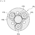
- the first transmission gear and the second transmission gear are each formed by a plurality of gears arranged around the input gear and the output gear respectively.
- the input gear and the output gear are each arranged so as to rotate on a mutually different plane, and one of the first transmission gear and the second transmission gear has a tooth-part width in the axial directions which is greater than the other, so that the one engages on the rotational planes of the input gear and the output gear.
- a bogie axle device includes: a pair of left and right axle units having a driving unit fixed to a chassis of a vehicle, a swing housing supported so as to swing freely by the driving unit, a pair of front and rear axles supported so as to rotate freely by the swing housing, and a driving-force transmitting mechanism which transmits a driving force inputted by the driving unit to the pair of front and rear axles; and a balance system according to claim 1, which suppresses a swing of the swing housing which is caused when the vehicle is running.
- the first transmission gear and the second transmission gear are each formed by a plurality of gears. Therefore, changes in the speed can be stably made between the input gear and the first transmission gear, between the first transmission gear and the second transmission gear and between the second transmission gear and the output gear.
- one of the first transmission gear and the second transmission gear has a tooth-part width in the axial directions which is greater than the other, and thereby, the input gear and the output gear are linked together. This makes it possible to reduce the size of the reaction-force separating mechanism.
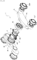
- Figs. 1 to 3 are a perspective view showing the exterior of a bogie axle device 1 according to this embodiment, a partly- exploded perspective view thereof and a sectional view of the main part respectively.
- the bogie axle device 1 includes: a driving unit 2 fixed to a chassis of a vehicle such as a harvester and a forwarder; a pair of left and right axle units 3L and 3R swinging freely relative to the driving unit 2; and a pair of left and right balance systems 4L and 4R arranged between the driving unit 2 and each of the axle units 3L and 3R respectively.
- the driving unit 2 includes: an input portion 21 for inputting a driving force outputted from an engine of the vehicle by means of a drive shaft (not shown) ; a unit housing 22 having a substantially cylinder shape, the input portion 21 being attached to the unit housing 22 on the vehicle-front side; and brake housings 23L and 23R each having a substantially cylinder shape and attached to the left and right ends of the unit housing 22 respectively.
- the unit housing 22 houses a differential mechanism which transmits the driving force inputted in the input portion 21 to the left and right axle units 3L and 3R.
- the brake housings 23L and 23R each house a brake mechanism which stops the axles from rotating.
- the brake housings 23L and 23R are each formed with attachment holes, and through the attachment holes, aplurality of bolts screwed into the unit housing 22 are inserted, so that the unit housing 22 and each of the brake housings 23L and 23R are linked together.
- the axle unit 3L includes: a swing housing 31L supported so as to swing freely by the driving unit 2, two axles 32LF and 32LR supported so as to rotate freely by the swing housing 31L, and a driving-force transmitting mechanism 33L arranged inside of the swing housing 31L which transmits the driving force inputted by the driving unit 2 to the two axles 32LF and 32LR.
- the driving-force transmitting mechanism 33L includes: an input gear 331L for inputting the driving force of the driving unit 2; a plurality of gears 332L and 333L which transmit the rotation of the input gear 331L up to the axles 32LF and 32LR; and the like.
- Tires (not shown) are each attached to the axles 32LF and 32LR.
- the axle unit 3R has the same formation as the axle unit 3L, and hence, a detailed description thereof is omitted.
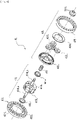
- the balance system 4L includes a reaction-force separating mechanism 41L, a planetary gear mechanism 42L and a revolving bearing 43L.
- the reaction-force separating mechanism 41L separates the driving force inputted by the driving unit 2 into a driving force transmitted to the driving-force transmitting mechanism 33L and a reaction force transmitted to the planetary gear mechanism 42L.
- the planetary gear mechanism 42L includes: a sun gear 421L uniting and rotating with a first carrier of the reaction-force separating mechanism 41L; a second carrier 422L fixed to the brake housing 23L of the driving unit 2, a planetary gear group 423L which is supported by the second carrier 422L and engages with the sun gear 421L; a ring-shaped holding plate 424L for holding the planetary gear group 423L on the second carrier 422L; and a ring gear 425L fixed to the swing housing 31L and engaging with the planetary gear group 423L.
- the revolving bearing 43L is a rolling ball bearing which supports the swing housing 31L so that the swing housing 31L can swing freely.
- the revolving bearing 43L includes: an inner ring 431L which is fixed, together with the second carrier 422L, to the brake housing 23L by means of shared bolts; and an outer ring 432L which is fixed, together with the ring gear 425L, to the swing housing 31L by means of shared bolts.
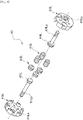
- the reaction-force separating mechanism 41L includes: an input gear 411L; a first transmission-gear group 412L; a second transmission-gear group 413L; an output gear 414L; and an inner carrier 415L and an outer carrier 416L which form the first carrier.
- the input gear 411L is united with an input shaft 411La for inputting the driving force from the driving unit 2.
- the input gear 411L is housed so as to rotate freely in the first carrier, and the input shaft 411La is inserted into the driving unit 2 through an opening 415La formed in the inner carrier 415L.
- the first transmission-gear group 412L is held on the first carrier so as to rotate freely and engages with the input gear 411L.
- the second transmission-gear group 413L is, in the same manner as the first transmission-gear group 412L, held on the first carrier so as to rotate freely.
- the second transmission-gear group 413L has a tooth-part width in the axial directions which is greater than the first transmission-gear group 412L, so that it can engage with the first transmission-gear group 412L and the output gear 414L.
- the output gear 414L is united with an output shaft 414La for outputting the driving force to the driving-force transmitting mechanism 33L.
- the output gear 414L is housed so as to rotate freely in the first carrier, and the output shaft 414La is inserted into the swing housing 31L through an opening 416La formed in the outer carrier 416L.
- the input gear 331L of the driving-force transmitting mechanism 33L is attached to the front end part of the output shaft 414La.
- the inner carrier 415L and the outer carrier 416L are supported, via ring-shaped sleeves 44La and 44Lb shown in Fig. 4 , as to be rotate freely by the second carrier 422L and the brake housing 23L.
- the inner carrier 415L and the outer carrier 416L rotate around the input gear 411L and the output gear 414L respectively.
- the opening 416La of the outer carrier 416L is formed on the inner surface with tooth rows in the axial directions.
- a cylindrical coupling 45L is inserted, and the tooth rows of the opening 416La engage with the tooth rows in the axial directions on the peripheral surface of the coupling 45L.
- the coupling 45L is formed with an opening for inserting the output shaft 414La.
- the front end part of the coupling 45L engages with the sun gear 421L of the planetary gear mechanism 42L, and thereby, the sun gear 421L unites and rotates with the first carrier.
- the balance system 4R has the same formation as the balance system 4L, and hence, a detailed description thereof is omitted.
- the driving unit 2 inputs the driving force in the input shaft 411La, and thereby, the input gear 411L is rotated.
- the rotation of the input gear 411L is transmitted to the output gear 414L via the first transmission-gear group 412L and the second transmission-gear group 413L.
- the rotation of the output shaft 414La which unites with the output gear 414L is transmitted to the axles 32LF and 32LR via the input gear 331L and the driving-force transmitting mechanism 33L.
- the tires attached to the axles 32LF and 32LR are rotated, and thereby, the vehicle provided with the bogie axle device 1 starts to run.
- the great torque of the driving unit 2 is inputted from the input gear 331L in the driving-force transmitting mechanism 33L. Then, the swinging torque Ts exerted on the swing housing 31L generates the reaction forces F1 and F2 on the axles 32LF and 32LR, and thereby, the load balance is lost between the front and rear wheels. In this case, the first carriers 415L and 416L start to rotate around the input gear 411L and the output gear 414L respectively. Consequently, the driving force of the driving unit 2 is separated into a driving force transmitted via the output gear 414L to the driving-force transmitting mechanism 33L and a reaction force transmitted via the sun gear 421L to the planetary gear mechanism 42L.
- the planetary gear mechanism 42L amplifies the reaction force inputted in the sun gear 421L by means of the planetary gear group 423L and the ring gear 425L, and then, transmits it to the swing housing 31L.
- the swing suppressing torque Tb for suppressing a swing of the swing housing 31L is exerted on the swing shaft Os of the swing housing 31L, thereby suppressing a swing of the swing housing 31L.
- the balance ratio (Tb/Ts) equivalent to the ratio of the swing suppressing torque Tb to the swinging torque Ts becomes approximately 90 %. Therefore, a swing of the swing housing 31L can be more effectively suppressed than the balance system of Patent Document 1 or 2.
- the reaction-force separating mechanism 41L separates a reaction force from the driving force of the driving unit, and thereafter, the planetary gear mechanism 42L amplifies the reaction force. Therefore, the speed-change ratio for the reaction force can be easily changed, thereby suppressing a swing of the swing housing 31L appropriately in different types of bogie axle devices.
- first transmission gear and the second transmission gear are each formed by a plurality of gears 412L and 413L respectively. Therefore, changes in the speed can be stably made between the input gear 411L and the first transmission-gear group 412L, between the first transmission-gear group 412L and the second transmission-gear group 413L and between the second transmission-gear group 413L and the output gear 414L. Further, the second transmission-gear group 413L has a wider tooth part in the axial directions, and thereby, the input gear 411L and the output gear 414L are linked together. This makes it possible to reduce the size of the reaction-force separating mechanism 41L.
- reaction-force separating mechanism 41L reduces the speed for the driving force inputted by the driving unit 2.
- reaction-force separating mechanism according to the present invention is also operable to increase the speed for the driving force, or output the driving force intact without changing the speed.
- Figs. 9(A), 9(B) and 9(C) are schematic side views of gears forming the reaction-force separating mechanism and plan views of the gears on the input side and the output side. These figures show, from the right side: a formation (A) for allowing the reaction-force separating mechanism to reduce the speed for the driving force; a formation (B), to amplify the speed; and a formation (C), not to change the speed.
- an input gear 51 having a relatively-small number of teeth engages with a first transmission gear 52 on the same plane
- the first transmission gear 52 engages with a second transmission gear 53
- the second transmission gear 53 engages with an output gear 54 having a larger number of teeth than the input gear 51.
- the input gear 51 has a relatively narrow diameter, and hence, a space to arrange the second transmission gear 53 can be secured on the same plane. This makes it possible to arrange seven gears in the first step on the input side and arrange four gears in the second step on the output side, which is the same as the first embodiment.
- an input gear 61 having a relatively-large number of teeth engages with a first transmission gear 62
- the first transmission gear 62 engages with a second transmission gear 63
- the second transmission gear 63 engages with an output gear 64 having a smaller number of teeth than the input gear 61.
- the input gear 61 has a relatively wide diameter, and hence, a space to arrange the second transmission gear 63 cannot be secured on the same plane. This requires arranging four gears in the first step and arranging seven gears in the second step on the output side. In other words, in order to increase the speed for the driving force, as compared with the reduction in the speed, the gear arrangement on the input side and on the output side needs to be reversed.
- an input gear 71 engages with a first transmission gear 72
- the first transmission gear 72 engages with a second transmission gear 73
- the second transmission gear 73 engages with an output gear 74 having the same number of teeth as the input gear 71.
- three steps are formed for the gear arrangement between the input side and the output side.
- the first transmission gear 72 is divided in two, and between them, the output gear 74 is arranged, thereby preventing the first transmission gear 72 from interfering with the output gear 74.
- the bogie device and the balance system according to the present invention can also be employed for self-propelling vehicles which require high running performance, such as an agricultural tractor, harvester or a combine harvester, and a scraper or the like for construction equipment.
Landscapes
- Engineering & Computer Science (AREA)
- Mechanical Engineering (AREA)
- Chemical & Material Sciences (AREA)
- Combustion & Propulsion (AREA)
- Transportation (AREA)
- Retarders (AREA)
- Arrangement Of Transmissions (AREA)
- Arrangement And Driving Of Transmission Devices (AREA)
Description
- The present invention relates to a balance system which is capable of, in a bogie axle device supporting two axles arranged in the front and rear directions of a vehicle such that the two axles swing freely, suppressing a swing of a swing housing supporting the two axles, and a bogie axle device provided with the balance system.
- For example, in the field of forestry, self-propelling vehicles are utilized, such as a harvester which fells, limbs and crosscuts trees or the like, and as shown in
Fig. 10 , aforwarder 82 which loads short trunk materials subjected to crosscutting onto acargo bed 81 by agrapple crane 80 and transports the trunk materials. Some harvesters and forwarders require higher running performance on hilly ground. In order to realize the performance, it is known that theforwarder 82 is also provided with abogie axle device 84, thebogie axle device 84 supporting twoaxles - As shown in
Fig. 11 , thebogie axle device 84 includes a driving unit (not shown) fixed to achassis 82a (seeFig. 10 ) of the vehicle, and a pair of left andright axle units 85 swinging freely relative to the driving unit. The driving unit transmits a driving force outputted from an engine of the vehicle to the left andright axle units 85. The pair of left andright axle units 85 each include: aswing housing 86 supported by the driving unit such that it swings freely relative to the driving unit; twoaxles swing housing 86; and a driving-force transmitting mechanism 87 which transmits a driving force inputted by the driving unit to the twoaxles force transmitting mechanism 87 includes aninput gear 87a for inputting the driving force of the driving unit therein, and a plurality of gears for transmitting the rotation of theinput gear 87a to theaxles - To the
axles tires tires tires swing housing 86, and thereby, a counterclockwise swinging torque Ts is exerted on a swing shaft Os of theswing housing 86. The swinging torque Ts is based upon a height L from the ground surface G up to the swing shaft Os and the reaction force F'. The tire rotating torque To, tangential force F, reaction force F' and swinging torque Ts are calculated by the following numerical formulas.



- To: tire rotating torque
- F: tangential force on the tire tread
- F': reaction force exerted on the swing housing
- Ts: swinging torque
- Ti: input torque into the driving-force transmitting mechanism
- i: reduction ratio of the driving-force transmitting mechanism
- R: tire radius
- L: height from the ground surface up to the swing center
- When the vehicle is at a halt, the same weight is exerted on the
axles force transmitting mechanism 87, the swinging torque Ts on theswing housing 86 generates upward and downward reaction forces F1 and F2 on theaxles bogie axle device 84 to lose the load balance largely between the front wheel and the rear wheel, thereby inverting theswing housing 86. Further, the load on the rear-wheel axle 83R becomes heavy, thereby causing some concern about the strength thereof. The reaction forces F1 and F2 for the swinging torque Ts are calculated by the following numerical formulas.
- In order to prevent the front wheel and the rear wheel from losing the load balance because of the swinging torque Ts, a conventional bogie axle device is provided with balance systems.
- The balance system of
EP0909671 includes two planetary gear mechanisms: a first-step planetary gear mechanism and a second-step planetary gear mechanism. A carrier output of the first-step planetary gear mechanism is inputted in a driving-force transmitting mechanism, and an output from a ring gear of the first-step planetary gear mechanism is inputted in a second-step planetary gear mechanism. In the second-step planetary gear mechanism, a ring gear is fixed to a swing housing, and from the ring gear, a swing suppressing torque Tb in the direction opposite to the swinging torque Ts is given to the swing housing, thereby suppressing a swing of the swing housing. In other words, in the balance system ofEP 0 909 671 , the driving force inputted from a driving unit is separated into a driving force inputted in the driving-force transmitting mechanism by the first-step planetary gear mechanism and a reaction force for suppressing a swing of the swing housing. Then, the second-step planetary gear mechanism amplifies the reaction force. - The balance system of
EP0 520 389 A2 includes two planetary gear mechanisms, each planetary gear group thereof being coaxially held by a shared carrier. A ring gear of a first-step planetary gear mechanism is fixed to the inside of a revolving bearing, the revolving bearing supporting a swing housing so that it can swing freely. This amplifies the driving force inputted from a driving unit, and the amplified driving force is inputted in a driving-force transmitting mechanism by the sun gear of a second-step planetary gear mechanism. Then, a ring gear of the second-step planetary gear mechanism is fixed to the swing housing, and a reaction force inputted from the second-step planetary gear mechanism works on the swing housing. As a result, the swing suppressing torque Tb in the direction opposite to the swinging torque Ts is given to the swing housing, thereby suppressing a swing of the swing housing. In other words, in the balance system ofEP 0 520 389 A2 , the first-step planetary gear mechanism amplifies the driving force inputted from the driving unit, and the second-step planetary gear mechanism separates it into the driving force inputted in the driving-force transmitting mechanism and the reaction force for suppressing a swing of the swing housing. - A balance system for a bogie axle device is capable of suppressing a swing of the swing housing more effectively as a balance ratio (Tb/Ts) becomes higher, the balance ratio being equivalent to the ratio of the swing suppressing torque Tb to the swinging torque Ts. A comparison will be made between the balance systems of Patent Document 1 (
EP0520389 ) and Patent Document 2 (EP0909671 ). In the balance system of Patent Document 1, a relatively high balance ratio of approximately 70 % can be obtained, but many structurally-complicated component parts are required, thereby increasing the costs. Specifically, the balance system needs four ring gears and four carriers, a ring gear which rotates inside of the first-step planetary gear mechanism, and the like. Further, the driving force is largely amplified in the first-step planetary gear mechanism, thereby causing some concern about the strength of the driving-force transmitting mechanism. - In contrast, the balance system of
Patent Document 2 is provided with only two left and right carriers, and the balance system does not require any component part having a complicated shape. Therefore, its costs are lower than the balance system of Patent Document 1, and the weight is also lighter. However, its balance ratio is approximately 40 % which is lower than Patent Document 1. Further, the revolving bearing can impose restraints on the size of a first-step ring gear thereof, and the first-step and second-step planetary gear mechanisms need to have the same number of teeth. This makes it impossible to enlarge the size of a second-step ring gear thereof to heighten the reduction ratio. Still further, the first-step planetary gear mechanism amplifies the driving force inputted from the driving unit, and the second-step planetary gear mechanism separates it into the driving force inputted in the driving-force transmitting mechanism and the reaction force exerted on the swing housing. This makes it impossible to even heighten the balance ratio simply by changing the reduction ratio on the side of the reaction force. - As described above, in the balance systems of the prior art, the production costs will increase if the balance ratio is raised, while the balance ratio will fall if the production costs are reduced. In short, conventionally, the balance system capable of obtaining a high balance ratio could not be produced at low cost.
- In order to solve the problems, it is an object of the present invention to provide a bogie axle device and a balance system which are capable of obtaining a high balance ratio at a low cost.
- In order to solve the problems, a balance system for a bogie axle device according to claim 1 is employed for a bogie axle device including: a driving unit fixed to a chassis of a vehicle; a swing housing supported so as to swing freely by the driving unit; a pair of front and rear axles supported so as to rotate freely by the swing housing; and a driving-force transmitting mechanism which transmits a driving force inputted by the driving unit to the pair of front and rear axles, and suppresses a swing of the swing housing which is caused when the vehicle is running. This balance system comprises a reaction-force separating mechanism and a planetary gear mechanism. The reaction-force separating mechanism includes: an input gear for inputting a driving force from the driving unit; an output gear for outputting the driving force to the driving-force transmitting mechanism; a first transmission gear engaging with the input gear; a second transmission gear engaging with the first transmission gear and the output gear; and a first carrier holding these gears and rotating freely around the input gear and the output gear. The planetary gear mechanism includes: a sun gear uniting and rotating with the first carrier; a planetary gear group which is supported by a second carrier fixed to the driving unit and engages with the sun gear; and a ring gear fixed to the swing housing and engaging with the planetary gear group.
- In the balance system for a bogie axle device according to claim 1, the reaction-force separating mechanism separates a reaction force from the inputted driving force, changes the speed for the reaction force and inputs it in the planetary gear mechanism. Then, the planetary gear mechanism amplifies the inputted reaction force and inputs it in the swing housing.
- According to
claim 2, in the balance system for a bogie axle device of claim 1, the first transmission gear and the second transmission gear are each formed by a plurality of gears arranged around the input gear and the output gear respectively. - According to claim 3, in the balance system for a bogie axle device of
claim 1 or 2, the input gear and the output gear are each arranged so as to rotate on a mutually different plane, and one of the first transmission gear and the second transmission gear has a tooth-part width in the axial directions which is greater than the other, so that the one engages on the rotational planes of the input gear and the output gear. - In addition, a bogie axle device according to claim 4 includes: a pair of left and right axle units having a driving unit fixed to a chassis of a vehicle, a swing housing supported so as to swing freely by the driving unit, a pair of front and rear axles supported so as to rotate freely by the swing housing, and a driving-force transmitting mechanism which transmits a driving force inputted by the driving unit to the pair of front and rear axles; and a balance system according to claim 1, which suppresses a swing of the swing housing which is caused when the vehicle is running.
- In claims 1 and 4, only one ring gear (two in total on the left and right sides) is employed, the ring gear being expensive. Therefore, the costs become lower than those of the balance systems of
Patent Documents 1 and 2. Further, the reaction-force separating mechanism separates, without using any ring gear, a reaction force from the driving force of the driving unit, and thereafter, the planetary gear mechanism amplifies the reaction force. Therefore, the speed-change ratio for the reaction force can be easily changed, thereby suppressing a swing of the swing housing appropriately in different types of bogie axle devices. - In
claim 2, the first transmission gear and the second transmission gear are each formed by a plurality of gears. Therefore, changes in the speed can be stably made between the input gear and the first transmission gear, between the first transmission gear and the second transmission gear and between the second transmission gear and the output gear. - In claim 3, one of the first transmission gear and the second transmission gear has a tooth-part width in the axial directions which is greater than the other, and thereby, the input gear and the output gear are linked together. This makes it possible to reduce the size of the reaction-force separating mechanism.
-
-
Fig. 1 is a perspective view showing an exterior shape of a bogie axle device. -
Fig. 2 is an exploded perspective view showing a configuration of the bogie axle device. -
Fig. 3 is a sectional view of the main part of the bogie axle device. -
Fig. 4 is an exploded perspective view showing a configuration of a balance system. -
Fig. 5 is an exploded perspective view showing a configuration of a reaction-force separating mechanism. -
Fig. 6 is a sectional view along the A-A line ofFig. 3 showing a configuration of the reaction-force separating mechanism. -
Fig. 7 is a sectional view along the B-B line ofFig. 3 showing a configuration of the reaction-force separating mechanism. -
Fig. 8 is a sectional view along the C-C line ofFig. 3 showing a configuration of the reaction-force separating mechanism. -
Figs. 9(A), 9(B) and 9(C) are illustrations showing a reaction-force separating mechanism according to a second embodiment. -
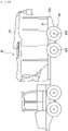
Fig. 10 is a side view of a forwarder provided with a bogie axle device. -
Fig. 11 is a side view showing a configuration of a conventional bogie axle device. - Embodiments of the present invention will be below described with reference to the drawings.
-
Figs. 1 to 3 are a perspective view showing the exterior of a bogie axle device 1 according to this embodiment, a partly- exploded perspective view thereof and a sectional view of the main part respectively. The bogie axle device 1 includes: a drivingunit 2 fixed to a chassis of a vehicle such as a harvester and a forwarder; a pair of left andright axle units driving unit 2; and a pair of left andright balance systems unit 2 and each of theaxle units - The driving
unit 2 includes: aninput portion 21 for inputting a driving force outputted from an engine of the vehicle by means of a drive shaft (not shown) ; aunit housing 22 having a substantially cylinder shape, theinput portion 21 being attached to theunit housing 22 on the vehicle-front side; andbrake housings unit housing 22 respectively. Theunit housing 22 houses a differential mechanism which transmits the driving force inputted in theinput portion 21 to the left andright axle units brake housings - The
brake housings unit housing 22 are inserted, so that theunit housing 22 and each of thebrake housings - The
axle unit 3L includes: aswing housing 31L supported so as to swing freely by the drivingunit 2, two axles 32LF and 32LR supported so as to rotate freely by theswing housing 31L, and a driving-force transmitting mechanism 33L arranged inside of theswing housing 31L which transmits the driving force inputted by the drivingunit 2 to the two axles 32LF and 32LR. The driving-force transmitting mechanism 33L includes: aninput gear 331L for inputting the driving force of thedriving unit 2; a plurality ofgears input gear 331L up to the axles 32LF and 32LR; and the like. Tires (not shown) are each attached to the axles 32LF and 32LR. Theaxle unit 3R has the same formation as theaxle unit 3L, and hence, a detailed description thereof is omitted. - As shown in
Figs. 3 to 5 andFigs. 6 to 8 equivalent to the A-A, B-B and C-C cross sections ofFig. 3 respectively, thebalance system 4L includes a reaction-force separating mechanism 41L, aplanetary gear mechanism 42L and a revolvingbearing 43L. The reaction-force separating mechanism 41L separates the driving force inputted by the drivingunit 2 into a driving force transmitted to the driving-force transmitting mechanism 33L and a reaction force transmitted to theplanetary gear mechanism 42L. - The
planetary gear mechanism 42L includes: asun gear 421L uniting and rotating with a first carrier of the reaction-force separating mechanism 41L; asecond carrier 422L fixed to thebrake housing 23L of thedriving unit 2, aplanetary gear group 423L which is supported by thesecond carrier 422L and engages with thesun gear 421L; a ring-shapedholding plate 424L for holding theplanetary gear group 423L on thesecond carrier 422L; and aring gear 425L fixed to theswing housing 31L and engaging with theplanetary gear group 423L. - The revolving
bearing 43L is a rolling ball bearing which supports theswing housing 31L so that theswing housing 31L can swing freely. The revolvingbearing 43L includes: aninner ring 431L which is fixed, together with thesecond carrier 422L, to thebrake housing 23L by means of shared bolts; and anouter ring 432L which is fixed, together with thering gear 425L, to theswing housing 31L by means of shared bolts. - The reaction-
force separating mechanism 41L includes: aninput gear 411L; a first transmission-gear group 412L; a second transmission-gear group 413L; anoutput gear 414L; and aninner carrier 415L and anouter carrier 416L which form the first carrier. Theinput gear 411L is united with an input shaft 411La for inputting the driving force from the drivingunit 2. Theinput gear 411L is housed so as to rotate freely in the first carrier, and the input shaft 411La is inserted into the drivingunit 2 through an opening 415La formed in theinner carrier 415L. - The first transmission-
gear group 412L is held on the first carrier so as to rotate freely and engages with theinput gear 411L. The second transmission-gear group 413L is, in the same manner as the first transmission-gear group 412L, held on the first carrier so as to rotate freely. The second transmission-gear group 413L has a tooth-part width in the axial directions which is greater than the first transmission-gear group 412L, so that it can engage with the first transmission-gear group 412L and theoutput gear 414L. - The
output gear 414L is united with an output shaft 414La for outputting the driving force to the driving-force transmitting mechanism 33L. Theoutput gear 414L is housed so as to rotate freely in the first carrier, and the output shaft 414La is inserted into theswing housing 31L through an opening 416La formed in theouter carrier 416L. To the front end part of the output shaft 414La, theinput gear 331L of the driving-force transmitting mechanism 33L is attached. - The
inner carrier 415L and theouter carrier 416L are supported, via ring-shaped sleeves 44La and 44Lb shown inFig. 4 , as to be rotate freely by thesecond carrier 422L and thebrake housing 23L. Theinner carrier 415L and theouter carrier 416L rotate around theinput gear 411L and theoutput gear 414L respectively. The opening 416La of theouter carrier 416L is formed on the inner surface with tooth rows in the axial directions. Into the opening 416La, acylindrical coupling 45L is inserted, and the tooth rows of the opening 416La engage with the tooth rows in the axial directions on the peripheral surface of thecoupling 45L. - The
coupling 45L is formed with an opening for inserting the output shaft 414La. The front end part of thecoupling 45L engages with thesun gear 421L of theplanetary gear mechanism 42L, and thereby, thesun gear 421L unites and rotates with the first carrier. Thebalance system 4R has the same formation as thebalance system 4L, and hence, a detailed description thereof is omitted. - Next, an operation of the embodiment will be described. In the bogie axle device 1, the driving
unit 2 inputs the driving force in the input shaft 411La, and thereby, theinput gear 411L is rotated. The rotation of theinput gear 411L is transmitted to theoutput gear 414L via the first transmission-gear group 412L and the second transmission-gear group 413L. Then, the rotation of the output shaft 414La which unites with theoutput gear 414L is transmitted to the axles 32LF and 32LR via theinput gear 331L and the driving-force transmitting mechanism 33L. As a result, the tires attached to the axles 32LF and 32LR are rotated, and thereby, the vehicle provided with the bogie axle device 1 starts to run. - The great torque of the
driving unit 2 is inputted from theinput gear 331L in the driving-force transmitting mechanism 33L. Then, the swinging torque Ts exerted on theswing housing 31L generates the reaction forces F1 and F2 on the axles 32LF and 32LR, and thereby, the load balance is lost between the front and rear wheels. In this case, thefirst carriers input gear 411L and theoutput gear 414L respectively. Consequently, the driving force of thedriving unit 2 is separated into a driving force transmitted via theoutput gear 414L to the driving-force transmitting mechanism 33L and a reaction force transmitted via thesun gear 421L to theplanetary gear mechanism 42L. - The
planetary gear mechanism 42L amplifies the reaction force inputted in thesun gear 421L by means of theplanetary gear group 423L and thering gear 425L, and then, transmits it to theswing housing 31L. As a result, the swing suppressing torque Tb for suppressing a swing of theswing housing 31L is exerted on the swing shaft Os of theswing housing 31L, thereby suppressing a swing of theswing housing 31L. In thebalance systems swing housing 31L can be more effectively suppressed than the balance system ofPatent Document 1 or 2. - As described above, in the
balance systems planetary gear mechanism 42L (two in total on the left and right sides) is employed, and hence, the costs become lower than those of any other conventional balance system. Further, the reaction-force separating mechanism 41L separates a reaction force from the driving force of the driving unit, and thereafter, theplanetary gear mechanism 42L amplifies the reaction force. Therefore, the speed-change ratio for the reaction force can be easily changed, thereby suppressing a swing of theswing housing 31L appropriately in different types of bogie axle devices. - In addition, the first transmission gear and the second transmission gear are each formed by a plurality of
gears input gear 411L and the first transmission-gear group 412L, between the first transmission-gear group 412L and the second transmission-gear group 413L and between the second transmission-gear group 413L and theoutput gear 414L. Further, the second transmission-gear group 413L has a wider tooth part in the axial directions, and thereby, theinput gear 411L and theoutput gear 414L are linked together. This makes it possible to reduce the size of the reaction-force separating mechanism 41L. - Next, a second embodiment of the present invention will be described. Some component elements are given the same reference numerals and characters if they are identical to those of the first embodiment, and a detailed description thereof is omitted. In the first embodiment, the example is described where the reaction-
force separating mechanism 41L reduces the speed for the driving force inputted by the drivingunit 2. However, the reaction-force separating mechanism according to the present invention is also operable to increase the speed for the driving force, or output the driving force intact without changing the speed. -
Figs. 9(A), 9(B) and 9(C) are schematic side views of gears forming the reaction-force separating mechanism and plan views of the gears on the input side and the output side. These figures show, from the right side: a formation (A) for allowing the reaction-force separating mechanism to reduce the speed for the driving force; a formation (B), to amplify the speed; and a formation (C), not to change the speed. - As shown in
Fig. 9(A) , in order to reduce the speed for the driving force, aninput gear 51 having a relatively-small number of teeth engages with afirst transmission gear 52 on the same plane, thefirst transmission gear 52 engages with asecond transmission gear 53, and thesecond transmission gear 53 engages with anoutput gear 54 having a larger number of teeth than theinput gear 51. In this formation, theinput gear 51 has a relatively narrow diameter, and hence, a space to arrange thesecond transmission gear 53 can be secured on the same plane. This makes it possible to arrange seven gears in the first step on the input side and arrange four gears in the second step on the output side, which is the same as the first embodiment. - Furthermore, as shown in
Fig. 9(B) , in order to increase the speed for the driving force, aninput gear 61 having a relatively-large number of teeth engages with afirst transmission gear 62, thefirst transmission gear 62 engages with asecond transmission gear 63, and thesecond transmission gear 63 engages with anoutput gear 64 having a smaller number of teeth than theinput gear 61. In this case, theinput gear 61 has a relatively wide diameter, and hence, a space to arrange thesecond transmission gear 63 cannot be secured on the same plane. This requires arranging four gears in the first step and arranging seven gears in the second step on the output side. In other words, in order to increase the speed for the driving force, as compared with the reduction in the speed, the gear arrangement on the input side and on the output side needs to be reversed. - Moreover, as shown in
Fig. 9(C) , in order to output the driving force at a constant speed with the speed remaining unchanged, aninput gear 71 engages with afirst transmission gear 72, thefirst transmission gear 72 engages with asecond transmission gear 73, and thesecond transmission gear 73 engages with anoutput gear 74 having the same number of teeth as theinput gear 71. In this case, three steps are formed for the gear arrangement between the input side and the output side. Thefirst transmission gear 72 is divided in two, and between them, theoutput gear 74 is arranged, thereby preventing thefirst transmission gear 72 from interfering with theoutput gear 74. - Although each embodiment of the present invention has been above described in detail, the present invention is not limited to the embodiments as specific configurations thereof. Within the scope of the present invention as defined by the appended claims, variations in design are possible. For example, the bogie device and the balance system according to the present invention can also be employed for self-propelling vehicles which require high running performance, such as an agricultural tractor, harvester or a combine harvester, and a scraper or the like for construction equipment.
-
- 1
- bogie axle device
- 2
- driving unit
- 3L, 3R
- axle unit
- 31L
- swing housing
- 32LF, 32LR
- axle
- 33L
- driving-force transmitting mechanism
- 4L, 4R
- balance system
- 41L
- reaction-force separating mechanism
- 411L
- input gear
- 412L
- first transmission-gear group
- 413L
- second transmission-gear group
- 414L
- output gear
- 415L
- inner carrier (first carrier)
- 416L
- outer carrier (first carrier)
- 42L
- planetary gear mechanism
- 421L
- sun gear
- 422L
- second carrier
- 425L
- ring gear
Claims (4)
- A balance system for a bogie axle device (1) which is employed for a bogie axle device including: a driving unit (2) fixed to a chassis of a vehicle; a swing housing (31L) supported so as to swing freely by the driving unit; a pair of front and rear axles supported so as to rotate freely by the swing housing; and a driving-force transmitting mechanism (33L) which transmits a driving force inputted by the driving unit to the pair of front and rear axles, and suppresses a swing of the swing housing (31L) which is caused when the vehicle is running, comprising:a reaction-force separating mechanism (41L) which includes an input gear (411L) for inputting a driving force from the driving unit, an output gear (414L) for outputting the driving force to the driving-force transmitting mechanism, a first transmission gear engaging with the input gear, a second transmission gear engaging with the first transmission gear and the output gear, and a first carrier holding these gears and rotating freely around the input gear and the output gear; anda planetary gear mechanism (42L) which: includes a sun gear (421L) uniting and rotating with the first carrier, a planetary gear group (423L) which is supported by a second carrier (422L) fixed to the driving unit and engages with the sun gear (421L), and a ring gear (425L) fixed to the swing housing (31L) and engaging with the planetary gear group (423L); and transmits, to the swing housing (31L), a reaction force for suppressing a swing of the swing housing.
- The balance system for a bogie axle device according to claim 1, wherein the first transmission gear and the second transmission gear are each formed by a plurality of gears (412L and 413L) arranged around the input gear (411L) and the output gear (414L) respectively.
- The balance system for a bogie axle device according to claim 1 or 2, wherein the input gear (411L) and the output gear (414L)are each arranged so as to rotate on a mutually different plane, and one of the first transmission gear and the second transmission gear has a tooth-part width in the axial directions which is greater than the other, so that the one engages on the rotational planes of the input gear and the output gear.
- A bogie axle device (1) which includes: a pair of left and right axle units having a driving unit (2) fixed to a chassis of a vehicle, a swing housing (31L) supported so as to swing freely by the driving unit, a pair of front and rear axles supported so as to rotate freely by the swing housing (31L), and a driving-force transmitting mechanism (33L) which transmits a driving force inputted by the driving unit to the pair of front and rear axles; and a balance system according to claim 1, which suppresses a swing of the swing housing (31L) which is caused when the vehicle is running.
Applications Claiming Priority (1)
| Application Number | Priority Date | Filing Date | Title |
|---|---|---|---|
| PCT/JP2016/059649 WO2017163406A1 (en) | 2016-03-25 | 2016-03-25 | Bogie axle device balance system and bogie axle device |
Publications (3)
| Publication Number | Publication Date |
|---|---|
| EP3434505A1 EP3434505A1 (en) | 2019-01-30 |
| EP3434505A4 EP3434505A4 (en) | 2020-02-26 |
| EP3434505B1 true EP3434505B1 (en) | 2022-05-11 |
Family
ID=59901293
Family Applications (1)
| Application Number | Title | Priority Date | Filing Date |
|---|---|---|---|
| EP16895437.8A Active EP3434505B1 (en) | 2016-03-25 | 2016-03-25 | Bogie axle device balance system and bogie axle device |
Country Status (3)
| Country | Link |
|---|---|
| EP (1) | EP3434505B1 (en) |
| JP (1) | JP6599547B2 (en) |
| WO (1) | WO2017163406A1 (en) |
Families Citing this family (1)
| Publication number | Priority date | Publication date | Assignee | Title |
|---|---|---|---|---|
| TWI890178B (en) * | 2023-10-30 | 2025-07-11 | 友達光電股份有限公司 | Autonomous mobile robot |
Family Cites Families (7)
| Publication number | Priority date | Publication date | Assignee | Title |
|---|---|---|---|---|
| DE2522542C3 (en) * | 1975-05-21 | 1979-11-15 | Valmet Oy, Helsinki | Drive arrangement of a motor vehicle |
| DE4120801A1 (en) * | 1991-06-24 | 1993-01-21 | Neunkirchner Masch Achsen | DRIVE DEVICE FOR TANDEMAXES |
| US6053837A (en) | 1997-10-15 | 2000-04-25 | Neunkirchener Maschinen - Und Achsenfabrik Gmbh & Co. Kg | Drive unit for a tandem axle |
| CA2522707A1 (en) * | 2004-10-29 | 2006-04-29 | Les Equipements Sigma Inc. | Log skidder |
| ATE419987T1 (en) * | 2006-09-22 | 2009-01-15 | Naf Neunkirchener Achsenfabrik | DRIVE DEVICE FOR TANDEM AXLES AND METHOD FOR DRIVING TANDEM AXLES |
| DE102009032286B4 (en) * | 2008-12-18 | 2022-01-05 | Schaeffler Technologies AG & Co. KG | Spur gear differential with positive and negative profile shift on the sun gears |
| EP2657059B1 (en) * | 2012-04-24 | 2018-08-08 | NAF Neunkirchener Achsenfabrik AG | Drive device for tandem axles |
-
2016
- 2016-03-25 JP JP2018506728A patent/JP6599547B2/en active Active
- 2016-03-25 WO PCT/JP2016/059649 patent/WO2017163406A1/en not_active Ceased
- 2016-03-25 EP EP16895437.8A patent/EP3434505B1/en active Active
Also Published As
| Publication number | Publication date |
|---|---|
| JPWO2017163406A1 (en) | 2019-01-24 |
| EP3434505A4 (en) | 2020-02-26 |
| JP6599547B2 (en) | 2019-10-30 |
| EP3434505A1 (en) | 2019-01-30 |
| WO2017163406A1 (en) | 2017-09-28 |
Similar Documents
| Publication | Publication Date | Title |
|---|---|---|
| US7841435B2 (en) | Transmission | |
| FI97873C (en) | Drive shaft for tandem axle | |
| US11780328B2 (en) | Drive device for an electrically driven axle of a motor vehicle | |
| EP3090930B1 (en) | Combination of a drive wheel and a gearbox for a continuous track system | |
| EP2944848A1 (en) | Differential assembly having a link shaft | |
| US20060276297A1 (en) | Tandem axle system | |
| US6085853A (en) | Drive system for multi-axle motor vehicle | |
| US6053837A (en) | Drive unit for a tandem axle | |
| US6755093B2 (en) | Planetary drive assembly with idlers for low floor vehicle | |
| US20170122422A1 (en) | Limited slip inter-axle differential | |
| EP3434505A1 (en) | Bogie axle device balance system and bogie axle device | |
| EP3317135B1 (en) | Final transmission for agricultural and industrial motor vehicles | |
| SE1250544A1 (en) | Drive shaft for a motor vehicle | |
| US6837820B1 (en) | Differential drive gear assembly | |
| US20070287568A1 (en) | Axle having dual planetary reduction | |
| US20170087984A1 (en) | Tandem axle gearing arrangement to reduce drive pinion bearing parasitic losses | |
| US7604562B2 (en) | Drive axle for a light vehicle | |
| EP4257388A1 (en) | Improved torque distributor system among axles of a heavy vehicle | |
| JP3503637B2 (en) | Agricultural traveling body | |
| US7520834B2 (en) | Multiple rear drive axles with common gearing | |
| EP4257389A1 (en) | Improved torque distribution system among axles of a heavy vehicle | |
| US7252173B2 (en) | Differential gear for a vehicle | |
| EP1659313A1 (en) | Transmission system | |
| US7051833B2 (en) | Gantry axle | |
| IT202300020277A1 (en) | IMPROVED TORQUE DISTRIBUTION SYSTEM BETWEEN HEAVY DUTY VEHICLE AXLES |
Legal Events
| Date | Code | Title | Description |
|---|---|---|---|
| STAA | Information on the status of an ep patent application or granted ep patent |
Free format text: STATUS: THE INTERNATIONAL PUBLICATION HAS BEEN MADE |
|
| PUAI | Public reference made under article 153(3) epc to a published international application that has entered the european phase |
Free format text: ORIGINAL CODE: 0009012 |
|
| STAA | Information on the status of an ep patent application or granted ep patent |
Free format text: STATUS: REQUEST FOR EXAMINATION WAS MADE |
|
| 17P | Request for examination filed |
Effective date: 20180912 |
|
| AK | Designated contracting states |
Kind code of ref document: A1 Designated state(s): AL AT BE BG CH CY CZ DE DK EE ES FI FR GB GR HR HU IE IS IT LI LT LU LV MC MK MT NL NO PL PT RO RS SE SI SK SM TR |
|
| AX | Request for extension of the european patent |
Extension state: BA ME |
|
| DAV | Request for validation of the european patent (deleted) | ||
| DAX | Request for extension of the european patent (deleted) | ||
| A4 | Supplementary search report drawn up and despatched |
Effective date: 20200127 |
|
| RIC1 | Information provided on ipc code assigned before grant |
Ipc: B60K 17/32 20060101AFI20200121BHEP Ipc: B60B 35/12 20060101ALI20200121BHEP Ipc: B60K 17/36 20060101ALI20200121BHEP |
|
| GRAP | Despatch of communication of intention to grant a patent |
Free format text: ORIGINAL CODE: EPIDOSNIGR1 |
|
| STAA | Information on the status of an ep patent application or granted ep patent |
Free format text: STATUS: GRANT OF PATENT IS INTENDED |
|
| INTG | Intention to grant announced |
Effective date: 20220126 |
|
| GRAS | Grant fee paid |
Free format text: ORIGINAL CODE: EPIDOSNIGR3 |
|
| GRAA | (expected) grant |
Free format text: ORIGINAL CODE: 0009210 |
|
| STAA | Information on the status of an ep patent application or granted ep patent |
Free format text: STATUS: THE PATENT HAS BEEN GRANTED |
|
| AK | Designated contracting states |
Kind code of ref document: B1 Designated state(s): AL AT BE BG CH CY CZ DE DK EE ES FI FR GB GR HR HU IE IS IT LI LT LU LV MC MK MT NL NO PL PT RO RS SE SI SK SM TR |
|
| REG | Reference to a national code |
Ref country code: GB Ref legal event code: FG4D |
|
| REG | Reference to a national code |
Ref country code: CH Ref legal event code: EP |
|
| REG | Reference to a national code |
Ref country code: AT Ref legal event code: REF Ref document number: 1491115 Country of ref document: AT Kind code of ref document: T Effective date: 20220515 |
|
| REG | Reference to a national code |
Ref country code: DE Ref legal event code: R081 Ref document number: 602016072164 Country of ref document: DE Owner name: OKUBO GEAR CO. LTD., ATSUGI-SHI, JP Free format text: FORMER OWNER: OKUBO GEAR CO. LTD., ATSUGI-SHI, KANAGAWA-KEN, JP |
|
| REG | Reference to a national code |
Ref country code: DE Ref legal event code: R096 Ref document number: 602016072164 Country of ref document: DE |
|
| REG | Reference to a national code |
Ref country code: IE Ref legal event code: FG4D |
|
| REG | Reference to a national code |
Ref country code: SE Ref legal event code: TRGR |
|
| REG | Reference to a national code |
Ref country code: LT Ref legal event code: MG9D |
|
| REG | Reference to a national code |
Ref country code: NL Ref legal event code: MP Effective date: 20220511 |
|
| REG | Reference to a national code |
Ref country code: AT Ref legal event code: MK05 Ref document number: 1491115 Country of ref document: AT Kind code of ref document: T Effective date: 20220511 |
|
| PG25 | Lapsed in a contracting state [announced via postgrant information from national office to epo] |
Ref country code: PT Free format text: LAPSE BECAUSE OF FAILURE TO SUBMIT A TRANSLATION OF THE DESCRIPTION OR TO PAY THE FEE WITHIN THE PRESCRIBED TIME-LIMIT Effective date: 20220912 Ref country code: NO Free format text: LAPSE BECAUSE OF FAILURE TO SUBMIT A TRANSLATION OF THE DESCRIPTION OR TO PAY THE FEE WITHIN THE PRESCRIBED TIME-LIMIT Effective date: 20220811 Ref country code: NL Free format text: LAPSE BECAUSE OF FAILURE TO SUBMIT A TRANSLATION OF THE DESCRIPTION OR TO PAY THE FEE WITHIN THE PRESCRIBED TIME-LIMIT Effective date: 20220511 Ref country code: LT Free format text: LAPSE BECAUSE OF FAILURE TO SUBMIT A TRANSLATION OF THE DESCRIPTION OR TO PAY THE FEE WITHIN THE PRESCRIBED TIME-LIMIT Effective date: 20220511 Ref country code: HR Free format text: LAPSE BECAUSE OF FAILURE TO SUBMIT A TRANSLATION OF THE DESCRIPTION OR TO PAY THE FEE WITHIN THE PRESCRIBED TIME-LIMIT Effective date: 20220511 Ref country code: GR Free format text: LAPSE BECAUSE OF FAILURE TO SUBMIT A TRANSLATION OF THE DESCRIPTION OR TO PAY THE FEE WITHIN THE PRESCRIBED TIME-LIMIT Effective date: 20220812 Ref country code: FI Free format text: LAPSE BECAUSE OF FAILURE TO SUBMIT A TRANSLATION OF THE DESCRIPTION OR TO PAY THE FEE WITHIN THE PRESCRIBED TIME-LIMIT Effective date: 20220511 Ref country code: ES Free format text: LAPSE BECAUSE OF FAILURE TO SUBMIT A TRANSLATION OF THE DESCRIPTION OR TO PAY THE FEE WITHIN THE PRESCRIBED TIME-LIMIT Effective date: 20220511 Ref country code: BG Free format text: LAPSE BECAUSE OF FAILURE TO SUBMIT A TRANSLATION OF THE DESCRIPTION OR TO PAY THE FEE WITHIN THE PRESCRIBED TIME-LIMIT Effective date: 20220811 Ref country code: AT Free format text: LAPSE BECAUSE OF FAILURE TO SUBMIT A TRANSLATION OF THE DESCRIPTION OR TO PAY THE FEE WITHIN THE PRESCRIBED TIME-LIMIT Effective date: 20220511 |
|
| PG25 | Lapsed in a contracting state [announced via postgrant information from national office to epo] |
Ref country code: RS Free format text: LAPSE BECAUSE OF FAILURE TO SUBMIT A TRANSLATION OF THE DESCRIPTION OR TO PAY THE FEE WITHIN THE PRESCRIBED TIME-LIMIT Effective date: 20220511 Ref country code: PL Free format text: LAPSE BECAUSE OF FAILURE TO SUBMIT A TRANSLATION OF THE DESCRIPTION OR TO PAY THE FEE WITHIN THE PRESCRIBED TIME-LIMIT Effective date: 20220511 Ref country code: LV Free format text: LAPSE BECAUSE OF FAILURE TO SUBMIT A TRANSLATION OF THE DESCRIPTION OR TO PAY THE FEE WITHIN THE PRESCRIBED TIME-LIMIT Effective date: 20220511 Ref country code: IS Free format text: LAPSE BECAUSE OF FAILURE TO SUBMIT A TRANSLATION OF THE DESCRIPTION OR TO PAY THE FEE WITHIN THE PRESCRIBED TIME-LIMIT Effective date: 20220911 |
|
| PG25 | Lapsed in a contracting state [announced via postgrant information from national office to epo] |
Ref country code: SM Free format text: LAPSE BECAUSE OF FAILURE TO SUBMIT A TRANSLATION OF THE DESCRIPTION OR TO PAY THE FEE WITHIN THE PRESCRIBED TIME-LIMIT Effective date: 20220511 Ref country code: SK Free format text: LAPSE BECAUSE OF FAILURE TO SUBMIT A TRANSLATION OF THE DESCRIPTION OR TO PAY THE FEE WITHIN THE PRESCRIBED TIME-LIMIT Effective date: 20220511 Ref country code: RO Free format text: LAPSE BECAUSE OF FAILURE TO SUBMIT A TRANSLATION OF THE DESCRIPTION OR TO PAY THE FEE WITHIN THE PRESCRIBED TIME-LIMIT Effective date: 20220511 Ref country code: EE Free format text: LAPSE BECAUSE OF FAILURE TO SUBMIT A TRANSLATION OF THE DESCRIPTION OR TO PAY THE FEE WITHIN THE PRESCRIBED TIME-LIMIT Effective date: 20220511 Ref country code: DK Free format text: LAPSE BECAUSE OF FAILURE TO SUBMIT A TRANSLATION OF THE DESCRIPTION OR TO PAY THE FEE WITHIN THE PRESCRIBED TIME-LIMIT Effective date: 20220511 Ref country code: CZ Free format text: LAPSE BECAUSE OF FAILURE TO SUBMIT A TRANSLATION OF THE DESCRIPTION OR TO PAY THE FEE WITHIN THE PRESCRIBED TIME-LIMIT Effective date: 20220511 |
|
| REG | Reference to a national code |
Ref country code: DE Ref legal event code: R097 Ref document number: 602016072164 Country of ref document: DE |
|
| PLBE | No opposition filed within time limit |
Free format text: ORIGINAL CODE: 0009261 |
|
| STAA | Information on the status of an ep patent application or granted ep patent |
Free format text: STATUS: NO OPPOSITION FILED WITHIN TIME LIMIT |
|
| PG25 | Lapsed in a contracting state [announced via postgrant information from national office to epo] |
Ref country code: AL Free format text: LAPSE BECAUSE OF FAILURE TO SUBMIT A TRANSLATION OF THE DESCRIPTION OR TO PAY THE FEE WITHIN THE PRESCRIBED TIME-LIMIT Effective date: 20220511 |
|
| 26N | No opposition filed |
Effective date: 20230214 |
|
| PG25 | Lapsed in a contracting state [announced via postgrant information from national office to epo] |
Ref country code: SI Free format text: LAPSE BECAUSE OF FAILURE TO SUBMIT A TRANSLATION OF THE DESCRIPTION OR TO PAY THE FEE WITHIN THE PRESCRIBED TIME-LIMIT Effective date: 20220511 |
|
| PG25 | Lapsed in a contracting state [announced via postgrant information from national office to epo] |
Ref country code: MC Free format text: LAPSE BECAUSE OF FAILURE TO SUBMIT A TRANSLATION OF THE DESCRIPTION OR TO PAY THE FEE WITHIN THE PRESCRIBED TIME-LIMIT Effective date: 20220511 |
|
| REG | Reference to a national code |
Ref country code: CH Ref legal event code: PL |
|
| GBPC | Gb: european patent ceased through non-payment of renewal fee |
Effective date: 20230325 |
|
| REG | Reference to a national code |
Ref country code: BE Ref legal event code: MM Effective date: 20230331 |
|
| PG25 | Lapsed in a contracting state [announced via postgrant information from national office to epo] |
Ref country code: LU Free format text: LAPSE BECAUSE OF NON-PAYMENT OF DUE FEES Effective date: 20230325 |
|
| REG | Reference to a national code |
Ref country code: IE Ref legal event code: MM4A |
|
| PG25 | Lapsed in a contracting state [announced via postgrant information from national office to epo] |
Ref country code: GB Free format text: LAPSE BECAUSE OF NON-PAYMENT OF DUE FEES Effective date: 20230325 |
|
| PG25 | Lapsed in a contracting state [announced via postgrant information from national office to epo] |
Ref country code: LI Free format text: LAPSE BECAUSE OF NON-PAYMENT OF DUE FEES Effective date: 20230331 Ref country code: IT Free format text: LAPSE BECAUSE OF FAILURE TO SUBMIT A TRANSLATION OF THE DESCRIPTION OR TO PAY THE FEE WITHIN THE PRESCRIBED TIME-LIMIT Effective date: 20220511 Ref country code: IE Free format text: LAPSE BECAUSE OF NON-PAYMENT OF DUE FEES Effective date: 20230325 Ref country code: GB Free format text: LAPSE BECAUSE OF NON-PAYMENT OF DUE FEES Effective date: 20230325 Ref country code: FR Free format text: LAPSE BECAUSE OF NON-PAYMENT OF DUE FEES Effective date: 20230331 Ref country code: CH Free format text: LAPSE BECAUSE OF NON-PAYMENT OF DUE FEES Effective date: 20230331 |
|
| PG25 | Lapsed in a contracting state [announced via postgrant information from national office to epo] |
Ref country code: BE Free format text: LAPSE BECAUSE OF NON-PAYMENT OF DUE FEES Effective date: 20230331 |
|
| PG25 | Lapsed in a contracting state [announced via postgrant information from national office to epo] |
Ref country code: BG Free format text: LAPSE BECAUSE OF FAILURE TO SUBMIT A TRANSLATION OF THE DESCRIPTION OR TO PAY THE FEE WITHIN THE PRESCRIBED TIME-LIMIT Effective date: 20220511 |
|
| PG25 | Lapsed in a contracting state [announced via postgrant information from national office to epo] |
Ref country code: BG Free format text: LAPSE BECAUSE OF FAILURE TO SUBMIT A TRANSLATION OF THE DESCRIPTION OR TO PAY THE FEE WITHIN THE PRESCRIBED TIME-LIMIT Effective date: 20220511 |
|
| PG25 | Lapsed in a contracting state [announced via postgrant information from national office to epo] |
Ref country code: CY Free format text: LAPSE BECAUSE OF FAILURE TO SUBMIT A TRANSLATION OF THE DESCRIPTION OR TO PAY THE FEE WITHIN THE PRESCRIBED TIME-LIMIT; INVALID AB INITIO Effective date: 20160325 |
|
| PG25 | Lapsed in a contracting state [announced via postgrant information from national office to epo] |
Ref country code: HU Free format text: LAPSE BECAUSE OF FAILURE TO SUBMIT A TRANSLATION OF THE DESCRIPTION OR TO PAY THE FEE WITHIN THE PRESCRIBED TIME-LIMIT; INVALID AB INITIO Effective date: 20160325 |
|
| PG25 | Lapsed in a contracting state [announced via postgrant information from national office to epo] |
Ref country code: TR Free format text: LAPSE BECAUSE OF FAILURE TO SUBMIT A TRANSLATION OF THE DESCRIPTION OR TO PAY THE FEE WITHIN THE PRESCRIBED TIME-LIMIT Effective date: 20220511 |
|
| PGFP | Annual fee paid to national office [announced via postgrant information from national office to epo] |
Ref country code: SE Payment date: 20260122 Year of fee payment: 11 |
|
| PGFP | Annual fee paid to national office [announced via postgrant information from national office to epo] |
Ref country code: DE Payment date: 20260202 Year of fee payment: 11 |