EP3434487A1 - Thermal printer - Google Patents
Thermal printer Download PDFInfo
- Publication number
- EP3434487A1 EP3434487A1 EP17904737.8A EP17904737A EP3434487A1 EP 3434487 A1 EP3434487 A1 EP 3434487A1 EP 17904737 A EP17904737 A EP 17904737A EP 3434487 A1 EP3434487 A1 EP 3434487A1
- Authority
- EP
- European Patent Office
- Prior art keywords
- ink ribbon
- cleaning
- thermal printer
- region
- conveyance
- Prior art date
- Legal status (The legal status is an assumption and is not a legal conclusion. Google has not performed a legal analysis and makes no representation as to the accuracy of the status listed.)
- Granted
Links
Images






Classifications
-
- B—PERFORMING OPERATIONS; TRANSPORTING
- B41—PRINTING; LINING MACHINES; TYPEWRITERS; STAMPS
- B41J—TYPEWRITERS; SELECTIVE PRINTING MECHANISMS, i.e. MECHANISMS PRINTING OTHERWISE THAN FROM A FORME; CORRECTION OF TYPOGRAPHICAL ERRORS
- B41J29/00—Details of, or accessories for, typewriters or selective printing mechanisms not otherwise provided for
- B41J29/17—Cleaning arrangements
-
- B—PERFORMING OPERATIONS; TRANSPORTING
- B41—PRINTING; LINING MACHINES; TYPEWRITERS; STAMPS
- B41J—TYPEWRITERS; SELECTIVE PRINTING MECHANISMS, i.e. MECHANISMS PRINTING OTHERWISE THAN FROM A FORME; CORRECTION OF TYPOGRAPHICAL ERRORS
- B41J11/00—Devices or arrangements of selective printing mechanisms, e.g. ink-jet printers or thermal printers, for supporting or handling copy material in sheet or web form
- B41J11/66—Applications of cutting devices
- B41J11/70—Applications of cutting devices cutting perpendicular to the direction of paper feed
-
- B—PERFORMING OPERATIONS; TRANSPORTING
- B41—PRINTING; LINING MACHINES; TYPEWRITERS; STAMPS
- B41J—TYPEWRITERS; SELECTIVE PRINTING MECHANISMS, i.e. MECHANISMS PRINTING OTHERWISE THAN FROM A FORME; CORRECTION OF TYPOGRAPHICAL ERRORS
- B41J2/00—Typewriters or selective printing mechanisms characterised by the printing or marking process for which they are designed
- B41J2/005—Typewriters or selective printing mechanisms characterised by the printing or marking process for which they are designed characterised by bringing liquid or particles selectively into contact with a printing material
- B41J2/01—Ink jet
- B41J2/17—Ink jet characterised by ink handling
- B41J2/175—Ink supply systems ; Circuit parts therefor
-
- B—PERFORMING OPERATIONS; TRANSPORTING
- B41—PRINTING; LINING MACHINES; TYPEWRITERS; STAMPS
- B41J—TYPEWRITERS; SELECTIVE PRINTING MECHANISMS, i.e. MECHANISMS PRINTING OTHERWISE THAN FROM A FORME; CORRECTION OF TYPOGRAPHICAL ERRORS
- B41J2/00—Typewriters or selective printing mechanisms characterised by the printing or marking process for which they are designed
- B41J2/315—Typewriters or selective printing mechanisms characterised by the printing or marking process for which they are designed characterised by selective application of heat to a heat sensitive printing or impression-transfer material
- B41J2/32—Typewriters or selective printing mechanisms characterised by the printing or marking process for which they are designed characterised by selective application of heat to a heat sensitive printing or impression-transfer material using thermal heads
-
- B—PERFORMING OPERATIONS; TRANSPORTING
- B41—PRINTING; LINING MACHINES; TYPEWRITERS; STAMPS
- B41J—TYPEWRITERS; SELECTIVE PRINTING MECHANISMS, i.e. MECHANISMS PRINTING OTHERWISE THAN FROM A FORME; CORRECTION OF TYPOGRAPHICAL ERRORS
- B41J2/00—Typewriters or selective printing mechanisms characterised by the printing or marking process for which they are designed
- B41J2/315—Typewriters or selective printing mechanisms characterised by the printing or marking process for which they are designed characterised by selective application of heat to a heat sensitive printing or impression-transfer material
- B41J2/32—Typewriters or selective printing mechanisms characterised by the printing or marking process for which they are designed characterised by selective application of heat to a heat sensitive printing or impression-transfer material using thermal heads
- B41J2/325—Typewriters or selective printing mechanisms characterised by the printing or marking process for which they are designed characterised by selective application of heat to a heat sensitive printing or impression-transfer material using thermal heads by selective transfer of ink from ink carrier, e.g. from ink ribbon or sheet
-
- B—PERFORMING OPERATIONS; TRANSPORTING
- B41—PRINTING; LINING MACHINES; TYPEWRITERS; STAMPS
- B41J—TYPEWRITERS; SELECTIVE PRINTING MECHANISMS, i.e. MECHANISMS PRINTING OTHERWISE THAN FROM A FORME; CORRECTION OF TYPOGRAPHICAL ERRORS
- B41J29/00—Details of, or accessories for, typewriters or selective printing mechanisms not otherwise provided for
- B41J29/38—Drives, motors, controls or automatic cut-off devices for the entire printing mechanism
-
- B—PERFORMING OPERATIONS; TRANSPORTING
- B41—PRINTING; LINING MACHINES; TYPEWRITERS; STAMPS
- B41J—TYPEWRITERS; SELECTIVE PRINTING MECHANISMS, i.e. MECHANISMS PRINTING OTHERWISE THAN FROM A FORME; CORRECTION OF TYPOGRAPHICAL ERRORS
- B41J2/00—Typewriters or selective printing mechanisms characterised by the printing or marking process for which they are designed
- B41J2/005—Typewriters or selective printing mechanisms characterised by the printing or marking process for which they are designed characterised by bringing liquid or particles selectively into contact with a printing material
- B41J2/01—Ink jet
- B41J2/135—Nozzles
- B41J2/165—Prevention or detection of nozzle clogging, e.g. cleaning, capping or moistening for nozzles
Definitions
- the present invention relates to a thermal printer having a function of cleaning a thermal head.
- Patent Document 1 discloses a structure for performing cleaning of a thermal head (hereinafter referred to as the "related structure A").
- a cassette head cleaner including a cleaning sheet is attached to a thermal printer, to perform cleaning of the thermal head.
- any attached substance deposited on the thermal head is removed.
- Patent Document 1 Japanese Patent Application Laid-Open No. 2016-193570
- the present invention has been made to solve such a problem, and an object thereof is to provide a thermal printer with which cleaning of a thermal head can be performed without the necessity of using a cassette head cleaner.
- a thermal printer performs a printing process for forming an image on recording paper using an ink ribbon having a function of performing cleaning of a thermal head by being heated.
- the thermal printer includes the thermal head having a function of emitting heat, and a printing control unit controlling the thermal head.
- the thermal printer performs a cleaning process of performing the cleaning of the thermal head.
- the thermal head applies, to the ink ribbon, heat of a heat quantity with which a dye applied onto the ink ribbon does not sublime and with which the cleaning is performed.
- the thermal printer uses an ink ribbon having a function of performing cleaning of a thermal head by being heated.
- the thermal printer performs a cleaning process of performing the cleaning of the thermal head.
- the thermal head applies, to the ink ribbon, heat of a heat quantity with which a dye applied onto the ink ribbon does not sublime and with which the cleaning is performed.
- cleaning of the thermal head can be performed without the necessity of using a cassette head cleaner.
- Fig. 1 is a block diagram showing the schematic structure of a thermal printer 100 according to a first embodiment of the present invention. Note that, for the sake of convenience, Fig. 1 also shows an information processing apparatus 200 not included in the thermal printer 100.
- the thermal printer 100 performs a printing process P for forming an image on recording paper 6, which will be described later, using an ink ribbon 7, which will be described later.
- the information processing apparatus 200 is an apparatus that controls the thermal printer 100.
- the information processing apparatus 200 is, for example, a PC (Personal Computer).
- the information processing apparatus 200 is operated by the user.
- the information processing apparatus 200 transmits a print instruction and image data D1 to the thermal printer 100.
- the printing execution operation is an operation for causing the thermal printer 100 to execute the printing process P.
- the print instruction is an instruction for causing the thermal printer 100 to execute the printing process P.
- the image data D1 is data of an image to be printed on the recording paper 6, which will be described later.
- the thermal printer 100 includes a storage unit 10, a control unit 20, a communication unit 30, and a thermal head 5.
- the storage unit 10 is memory that stores various types of data, programs and the like.
- the storage unit 10 is, for example, structured by non-volatile memory and volatile storage memory.
- the storage unit 10 stores, for example, a control program for controlling the thermal printer 100, data relating to control of printing, image data, print data, various types of data, various types of set values, various types of initial values and the like.
- the thermal head 5 has a function of emitting heat. While details will be described later, the thermal head 5 emits heat in accordance with control of the control unit 20.
- control unit 20 performs various processes on the units of the thermal printer 100.
- the control unit 20 performs the various processes according to a control program.
- the control unit 20 is, for example, a processor such as a CPU (Central Processing Unit).
- the control unit 20 includes a control unit 21, a printing control unit 22, and a machine control unit 23. All or part of the control unit 21, the printing control unit 22, and the machine control unit 23 are structured by a signal processing circuit structured by a hardware electric circuit. Note that, all or part of the control unit 21, the printing control unit 22, and the machine control unit 23 may be a program module executed by the control unit 20.
- control unit 21 mainly performs a process of controlling the entire thermal printer 100. Further, the control unit 21 makes access to the storage unit 10, and reads out data and the like stored in the storage unit 10 as necessary.
- the control unit 21 includes a calculation unit 21a.
- the calculation unit 21a is described in the following.
- the calculation unit 21a is a program module executed by the control unit 21.
- the calculation unit 21a is realized by the control unit 21 performing various types of processes in accordance with a software program stored in memory or the like.
- the calculation unit 21a may be structured by a signal processing circuit structured by a hardware electric circuit that performs the various types of processes.
- the printing control unit 22 controls the thermal head 5. While details will be described later, the printing control unit 22 performs a process for performing printing, using the thermal head 5. While details will be described later, the machine control unit 23 controls a mechanical structure included in the thermal printer 100 (hereinafter also referred to as the "mechanical structure") in accordance with control of the control unit 21. That is, the control unit 21 controls the mechanical structure via the machine control unit 23.
- the mechanical structure included in the thermal printer 100
- the communication unit 30 communicates with the information processing apparatus 200 and the control unit 21.
- the print instruction and the image data D1 transmitted by the information processing apparatus 200 are transmitted to the control unit 21 via the communication unit 30.
- the communication unit 30 establishes communication using, for example a USB (Universal Serial Bus) interface.
- the control unit 21 According to the received print instruction, the control unit 21 generates print data using the received image data D1.
- the print data is control data for printing an image represented by image data D1 on the recording paper 6.
- the control unit 21 transmits the print data to the printing control unit 22.
- the printing control unit 22 controls the quantity of heat emitted by the thermal head 5.
- the image represented by the image data D1 is printed on the recording paper 6.
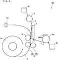
- Fig. 2 is a diagram mainly showing the mechanical structure for performing printing in the thermal printer 100 according to the first embodiment of the present invention. Note that, Fig. 2 shows the state where roll paper 6r and an ink ribbon 7 are attached to the thermal printer 100.
- the roll paper 6r is formed by elongated recording paper 6 being rolled up.
- the ink ribbon 7 is an elongated sheet. By one end of the ink ribbon 7 being rolled up, an ink ribbon roll 7r is formed.
- the ink ribbon roll 7r is a roll that supplies the ink ribbon 7 (hereinafter also referred to as the "supply-side roll").
- the ink ribbon roll 7rm is a roll for taking up the ink ribbon 7 (hereinafter also referred to as the "take-up-side roll").
- the thermal printer 100 is structured so that the ink ribbon rolls 7r, 7rm are removably attached to the thermal printer 100.
- the thermal printer 100 performs a printing process P for forming an image on the recording paper 6. While details will be described later, the printing process P is a process for transferring dyes 7y, 7m, 7c onto the recording paper 6.
- Fig. 3 is a diagram for describing part of the ink ribbon 7. Note that, Fig. 3 also shows sensors SN1, SN2 which will be described later. In Fig. 3 , an X direction and a Y direction are perpendicular to each other. The X direction and the Y direction appearing in the subsequent drawings are also perpendicular to each other.
- a direction including the X direction and a direction opposite to the X direction is also referred to as the "X-axis direction”.
- a direction including the Y direction and a direction opposite to the Y direction is also referred to as the "Y-axis direction”.
- a plane including the X-axis direction and the Y-axis direction is also referred to as the "XY-plane”.
- the ink ribbon 7 is provided with a plurality of unit regions R10 each including dyes 7y, 7m, 7c and a protective material 7op, along the longitudinal direction (X-axis direction) of the ink ribbon 7. That is, onto the ink ribbon 7, the dyes 7y, 7m, 7c and the protective material 7op are applied.
- Each of the dyes 7y, 7m, 7c and the protective material 7op is a material transferred onto the recording paper 6.
- Each of the dyes 7y, 7m, 7c and the protective material 7op is a transferred material that is transferred onto the recording paper 6 by being heated by the thermal head 5.
- the dye 7y is a first transferred material. That is, the dye 7y is the material that is firstly transferred onto the recording paper 6 in the printing process P.
- the protective material 7op is a fourth transferred material.
- Each of the dyes 7y, 7m, 7c shows a color to be transferred onto the recording paper 6 being the target of transfer.
- the dyes 7y, 7m, 7c show the colors of yellow, magenta, and cyan, respectively.
- yellow, magenta, and cyan are also referred to as “Ye”, “Mg”, and “Cy”, respectively.
- each of the dyes Ye, Mg, and Cy is also referred to as the "color dye”.
- Each of the dyes 7y, 7m, 7c being the color dye is a dye used in forming an image.
- the protective material 7op is a material for protecting the colors transferred onto the recording paper 6 (overcoat). Specifically, the protective material 7op is a material for protecting an image formed by the dyes 7y, 7m, 7c on the recording paper 6. Hereinafter, the protective material 7op is also referred to as the "OP material”.
- Each of the dyes 7y, 7m, 7c and the protective material 7op being the transferred material includes a transfer region Rt1. That is, the transfer regions Rt1 exist in the ink ribbon 7.
- the transfer region Rt1 is a transfer-source area in each of the transferred materials.
- a dye (dyes 7y, 7m, 7c) used in forming an image is applied.
- a region for forming an image is also referred to as an "image forming region".
- the shape and size of the image forming region are equal to the shape and size of the transfer region Rt1 shown in Fig. 3 .
- the direction in which the ink ribbon 7 is conveyed for forming an image at the image forming region of the recording paper 6 is also referred to as the "forward conveyance direction”. In Fig. 3 , the forward conveyance direction is the -X direction.
- the dye 7y is firstly transferred onto the image forming region of the recording paper 6. Thereafter, the dye 7m, 7c, and the protective material 7op are transferred onto the image forming region in order of the dye 7m, 7c, and the protective material 7op. Thus, an image represented by the dyes 7y, 7m, 7c is formed at the image forming region.
- the dye 7y is also referred to as the "transferred material ma1".
- the dye 7m is also referred to as the “transferred material mb2”.
- the dye 7c is also referred to as the “transferred material mb3”.
- the protective material 7op is also referred to as the "transferred material mb4".
- each of the transferred materials mb2, mb3, mb4 is also referred to as the "transferred material mb".
- the transferred material mb is a transferred material that is transferred secondly and later in the printing process P.
- the ink ribbon 7 is provided with a plurality of marks MK1a and a plurality of marks MK1s.
- the mark MK1a is a mark for specifying the position of the transferred material mb.
- Each of the mark MK1a and the mark MK1s is, for example, formed by a black-color material.
- the mark MK1a is provided in association with the transferred material mb. Specifically, the mark MK1a is provided at a region on the forward conveyance direction (the -X direction) side relative to the transferred material mb in the ink ribbon 7, so that the mark MK1a becomes adjacent to the transferred material mb.
- the transferred material mb is the dye 7m (the transferred material mb2).
- the mark MK1a is provided at a region on the forward conveyance direction (the -X direction) side relative to the dye 7m in the ink ribbon 7, so that the mark MK1a becomes adjacent to the dye 7m.
- the mark MK1s is a mark for specifying the position of the dye 7y (the transferred material ma1) being the first transferred material.
- the mark MK1s is provided in association with the dye 7y. Specifically, the mark MK1s is provided at the region on the forward conveyance direction (-X direction) side relative to the dye 7y in the ink ribbon 7, so that the mark MK1s becomes adjacent to the dye 7y.
- the thermal printer 100 further includes a conveyance roller pair 13, a platen roller 15, a conveyance unit 40, a sensor SN10, and a cut part Ct1.
- Fig. 4 is a diagram mainly showing a mechanism that conveys the ink ribbon 7 in the thermal printer 100 according to the first embodiment of the present invention (hereinafter also referred to as the "conveyance mechanism").
- Part (a) in Fig. 4 is a side view of the conveyance mechanism. Note that, in part (a) in Fig. 4 , for the sake of easier understanding of the conveyance mechanism, part of the constituents (for example, the ink ribbon roll 7rm) is shown at a position different from the actual position.
- the X direction, the Y direction, and the Z direction are perpendicular to each other.
- the X direction, the Y direction, and the Z direction are perpendicular to each other.
- a direction including the X direction and a direction opposite to the X direction is also referred to as the "the X-axis direction”.
- a direction including the Y direction and a direction opposite to the Y direction is also referred to as "the Y-axis direction”.
- a direction including the Z direction and a direction opposite to the Z direction (the -Z direction) is also referred to as "the Z-axis direction”.
- a plane including the X-axis direction and the Y-axis direction is also referred to as "the XY-plane”.
- a plane including the X-axis direction and the Z-axis direction is also referred to as "the XZ-plane”.
- a plane including the Y-axis direction and the Z-axis direction is also referred to as "the YZ-plane”.
- Part (b) in Fig. 4 is a plan view of the conveyance mechanism.
- the conveyance roller pair 13 is a roller pair for conveying the recording paper 6.
- the conveyance roller pair 13 is structured by a grip roller 13a and a pinch roller 13b.
- the grip roller 13a rotates by being driven by a rotary driver unit (not shown) such as a motor.
- the platen roller 15 is in contact with the recording paper 6 conveyed by the conveyance roller pair 13.
- the platen roller 15 is provided so as to oppose to part of the thermal head 5.
- the conveyance unit 40 is a mechanism for conveying the ink ribbon 7.
- the conveyance unit 40 is structured by ink conveyance units 80, 90. While details will be described later, the ink conveyance unit 80 conveys the ink ribbon 7 in the forward conveyance direction (the -X direction) in accordance with control of the machine control unit 23.
- an amount by which the ink ribbon 7 is transferred is also referred to as the "conveyance amount”.
- the conveyance amount is also a distance by which the ink ribbon 7 travels.
- the ink conveyance unit 80 has a function of controlling the conveyance amount of the ink ribbon 7 using an encoder 11 which will be described later.
- a direction opposite to the forward conveyance direction is also referred to as the "reverse conveyance direction".
- the reverse conveyance direction is the X direction. While details will be described later, the ink conveyance unit 90 conveys the ink ribbon 7 in the reverse conveyance direction (the X direction) in accordance with the machine control unit 23.
- Fig. 5 is a diagram for describing the structure of the ink conveyance unit 80.
- Part (a) in Fig. 5 is a diagram showing the structure of the ink conveyance unit 80 along the XZ-plane.
- Part (b) in Fig. 5 is a diagram showing the structure of the encoder 11, which will be described later, included in the ink conveyance unit 80 along the YZ-plane.
- the ink conveyance unit 80 includes an attachment 81, a take-up-side gear 82, a motor gear 83, a motor MT2, and the encoder 11.
- the attachment 81 is fixed to the side surface of the ink ribbon roll 7rm.
- the motor gear 83 is a bar-like member. On the outer surface of the motor gear 83, a gear is provided.
- the motor gear 83 is attached to the motor MT2.
- the motor MT2 causes the motor gear 83 to rotate in accordance with control of the machine control unit 23.
- the take-up-side gear 82 is fixed to the attachment 81. Further, the take-up-side gear 82 is provided so as to mesh with the gear at the outer surface of the motor gear 83. Thus, the motor MT2 causes the motor gear 83 to rotate, thereby successfully causing the ink ribbon roll 7rm to rotate via the take-up-side gear 82 and the attachment 81.
- the motor MT2 exerts control for conveying the ink ribbon 7 in the forward conveyance direction (the -X direction). Specifically, the motor MT2 causes the motor gear 83 to rotate so that the take-up-side gear 82 rotates in the counterclockwise direction, thereby causing the ink ribbon roll 7rm to rotate in the counterclockwise direction. Thus, the ink ribbon 7 is conveyed in the forward conveyance direction (the -X direction).
- the ink ribbon roll 7r also rotates so that the tension applied to the ink ribbon 7 is maintained at a constant value. Accordingly, in accordance with the ink ribbon roll 7rm taking up part of the ink ribbon 7, the ink ribbon roll 7r supplies the ink ribbon 7 by the length of the taken up ink ribbon 7.
- the encoder 11 is structured by a rotary member 84 and a sensor SN20.
- the rotary member 84 is a disc-like member.
- the rotary member 84 is fixed to an end of the motor gear 83.
- the rotary member 84 rotates in accordance with the rotation of the motor gear 83.
- the rotary member 84 is provided with a not-shown plurality of slits arranged circularly.
- the sensor SN20 has a function of detecting each of the slits of the rotating rotary member 84. Every time the sensor SN20 detects the slit of the rotary member 84, the sensor SN20 transmits a pulse (signal) to the control unit 21 via the machine control unit 23.
- the ink conveyance unit 90 includes an attachment 91, a supply-side gear 92, a motor gear 93, a torque limiter 94, and a motor MT1.
- the attachment 91 is fixed to the side surface of the ink ribbon roll 7r.
- the supply-side gear 92 is fixed to the attachment 91. Note that, to the supply-side gear 92, the torque limiter 94 for adjusting the rotary force (torque) of the ink ribbon roll 7r is provided. A gear is provided at the side surface of the supply-side gear 92.
- the motor gear 93 is attached to the motor MT1.
- the motor gear 93 is provided so as to mesh with the gear at the side surface of the supply-side gear 92.
- the motor MT1 causes the motor gear 93 to rotate in accordance with control of the machine control unit 23.
- the motor MT1 causes the motor gear 93 to rotate, thereby successfully causing the ink ribbon roll 7r to rotate via the supply-side gear 92 and the attachment 91.
- the motor MT1 exerts control for conveying the ink ribbon 7 in the reverse conveyance direction (the X direction). Specifically, the motor MT1 causes the motor gear 93 to rotate so that the supply-side gear 92 (the ink ribbon roll 7r) rotates in the clockwise direction. Thus, the ink ribbon 7 is conveyed in the reverse conveyance direction (the X direction). That is, the operation of the motor MT1 allows the ink ribbon roll 7rm to take up the ink ribbon 7. Note that, in accordance with the rotation of the ink ribbon roll 7r, the ink ribbon roll 7rm also rotates.
- the path along which the ink ribbon 7 is conveyed is also referred to as the "conveyance path".
- the sensor SN10 has a function of detecting the mark MK1a and the mark MK1s while the ink ribbon 7 is being conveyed by the conveyance unit 40.
- the sensor SN10 is provided upstream to the thermal head 5 in the conveyance path along which the ink ribbon 7 is conveyed.
- the sensor SN10 has a function of measuring the light transmittance of the ink ribbon 7 using light. In other words, the sensor SN10 has a function of detecting the mark MK1a and the mark MK1s using the light transmittance of the ink ribbon 7.
- the sensor SN10 is structured by a sensor SN1 and a sensor SN2.
- the sensor SN1 is identical to the sensor SN2 in the structure and the function.
- the sensor SN1 has a function of detecting the mark MK1a and the mark MK1s. That is, the mark MK1s is provided at a region in the ink ribbon 7 to be detected by both of the sensor SN1 and the sensor SN2. That is, the length in the Y-axis direction of the mark MK1s is greater than the length in the Y-axis direction of the mark MK1a, so as to be capable of being detected by both of the sensor SN1 and the sensor SN2.
- the sensor SN2 has a function of detecting the mark MK1s.
- each of the sensor SN1 and the sensor SN2 has a function of measuring the light transmittance of the ink ribbon 7 using light.
- the sensor SN1 is structured by a light emission unit SN1a and a light reception unit SN1b.
- the light emission unit SN1a and the light reception unit SN1b are provided so that the ink ribbon 7 is interposed between them.
- the sensor SN2 is structured by a light emission unit SN2a and a light reception unit SN2b.
- the light emission unit SN2a and the light reception unit SN2b are provided so that the ink ribbon 7 is interposed between them.
- the light emission unit SN2a and the light reception unit SN2b are identical in function to the light emission unit SN1a and the light reception unit SN1b, respectively.
- a region where the sensors SN1, SN2 are provided is also referred to as the "sensor region”.
- the sensor region is, for example in part (b) in Fig. 4 , a region where each of the sensors SN1, SN2 are provided.
- light emitted by the light emission unit SN1a of the sensor SN1, or light emitted by the light emission unit SN2a of the sensor SN2 is also referred to as the "sensor light”.
- a region where one of the color dye and the protective material 7op is applied is also referred to as the "transferred material region R1g".
- the color dye is one of the dyes 7y, 7m, 7c.
- a region where one of the marks MK1a, MK1s is provided is also referred to as the "mark region R1b".
- a region other than the transferred material region R1g and the mark region R1b is also referred to as the "blank region R1n".
- the blank region R1n is, for example, a transparent region.
- the ratio of the quantity of light received by the light reception unit SN1b to the quantity of light emitted by the light emission unit SN1a is also referred to as the "light transmittance" or the "light transmittance Tr".
- the light emission unit SN1a emits light toward the ink ribbon 7.
- the light reception unit SN1b receives, out of the light emitted by the light emission unit SN1a, light having transmitted through one of the transferred material region R1g, the mark region R1b, and the blank region R1n included in the ink ribbon 7.
- the light reception unit SN1b calculates the light transmittance, which is the ratio of the quantity of light received by the light reception unit SN1b to the quantity of light emitted by the light emission unit SN1a.
- the sensor SN1 constantly measures the light transmittance.
- the sensor SN1 is constantly transmitting a detection signal to the control unit 21 via the machine control unit 23.
- the sensor SN1 sets the level of the detection signal to the L-level.
- the threshold value Th1 is a value for detecting the marks MK1a, MK1s.
- the threshold value Th1 is a value that falls within, for example, a range of values 0.01 times to 0.2 times as great as the light transmittance of the blank region R1n.
- the light reception unit SN1b determines that the latest light transmittance is less than the threshold value Th1.
- the sensor SN1 detects one of the marks MK1a, MK1 s.
- the sensor SN1 sets the level of the detection signal to the L-level over the period in which one of the marks MK1a, MK1s is being detected. Further, when the latest light transmittance is equal to or greater than the threshold value Th1, the sensor SN1 sets the level of the detection signal to the H-level.
- the sensor SN1 is identical to the sensor SN2 in the structure and the function. Accordingly, the operation and the structure of the sensor SN2 (the light emission unit SN2a and the light reception unit SN2b) are similar to those of the sensor SN1 (the light emission unit SN1a and the light reception unit SN1b) and, therefore, a detailed description thereof is not repeated.
- the sensor SN2 performs the sensor process. That is, the light emission unit SN2a and the light reception unit SN2b perform the sensor process similarly to the light emission unit SN1a and the light reception unit SN1b.
- the position where the thermal head 5 emits heat (a heater line) is also referred to as the "heating position LC1".
- the heating position LC1 is, for example, the position shown in Fig. 4 .
- the sensor SN10 is provided at the position upstream to the thermal head 5 in the conveyance path along which the ink ribbon 7 is conveyed. That is, the sensor SN10 (the sensors SN1, SN2) is provided at a position upstream to the heating position LC1 (the heater line) in the conveyance path along which the ink ribbon 7 is conveyed.
- the direction in which the recording paper 6 is conveyed is also referred to as the "paper conveyance direction”.
- the length in the paper conveyance direction of the above-described image forming region in the recording paper 6 is also referred to as the "transfer length Lsp".
- the direction in which the ink ribbon 7 is conveyed is also referred to as the "ribbon conveyance direction”.
- the ribbon conveyance direction is the X-axis direction including the above-described forward conveyance direction (the -X direction) and reverse conveyance direction (the X direction).
- the length in the ribbon conveyance direction (X-axis direction) of the transfer region Rt1 in the ink ribbon 7 is also referred to as the "transfer length Lsa".
- the transfer length Lsa is the same as the transfer length Lsp.
- a direction in which the recording paper 6 is conveyed for forming an image at the image forming region of the recording paper 6 is also referred to as the "paper forward conveyance direction".
- the paper forward conveyance direction is the -X direction.
- the direction opposite to the paper forward conveyance direction is also referred to as the "paper reverse conveyance direction”.
- the paper reverse conveyance direction is a direction in which the recording paper 6 travels toward the ejection side.
- the paper reverse conveyance direction is the X direction.
- the printing process P is a process of transferring the first to fourth transferred materials in order onto the image forming region of the recording paper 6.
- the first to fourth transferred materials are the dyes 7y, 7m, 7c, and the protective material 7op, respectively. Note that, for the sake of brevity, immediately before the printing process P is performed, it is assumed that the position of the leading end of the image forming region of the recording paper 6 and the position of the leading end of the transfer region Rt1 in the first transferred material in the ink ribbon 7 are each at the heating position LC1.
- the state of the platen roller 15 being in contact with the thermal head 5 via the recording paper 6 and the ink ribbon 7 is also referred to as the "platen contact state”. Further, hereinafter, the state of the platen roller 15 being spaced apart from the recording paper 6 is also referred to as the "platen non-contact state”. The printing process P is performed in the situation where the platen roller 15 is in the platen contact state.
- a unit printing process is performed.
- a ribbon conveyance process, a paper conveyance process, and a transfer process are performed simultaneously.
- the following ribbon conveyance process, paper conveyance process, and transfer process are performed in the state where, as a result of the ink ribbon 7 being conveyed by control of the control unit 21, the heater line (the heating position LC1) is at the position of the leading end of the transfer region Rt1 in the transferred material.
- the leading end of the transfer region Rt1 is, for example, the left end in the X-axis direction of the transfer region Rt1 in the dye 7y in part (b) in Fig. 4 .
- the ink ribbon 7 is unreeled from the ink ribbon roll 7r by a transfer length Lsa.
- the ink ribbon 7 is conveyed over a predetermined time. Note that, in the ribbon conveyance process, in the state where the ink ribbon 7 is in contact with the thermal head 5, the conveyance unit 40 conveys the ink ribbon 7 in the forward conveyance direction (the -X direction).
- the recording paper 6 is conveyed by the conveyance roller pair 13. Specifically, by the conveyance roller pair 13, the recording paper 6 is unreeled from the roll paper 6r by a transfer length Lsp. Thus, the recording paper 6 is conveyed over a predetermined time as being interposed in the conveyance roller pair 13.
- the thermal head 5 heats a u-th transferred material at the heating position LC1.
- u is a natural number equal to or greater than 1.
- the quantity of heat applied by the thermal head 5 is controlled by the printing control unit 22 based on the above-described print data.
- the transferred material of the ink ribbon 7 is transferred onto the image forming region of the recording paper 6.
- the ink ribbon 7 is taken up by the ink ribbon roll 7rm, so that the position of the leading end of the transfer region Rt1 in the next transferred material is set to the heating position LC1. Further, the recording paper 6 is taken up by the roll paper 6r so that the position of the leading end of the image forming region in the recording paper 6 is set to the heating position LC1.
- the foregoing unit printing process is performed similarly as to each of the second to fourth transferred materials. Then, the printing process P ends.
- the dyes 7y, 7m, 7c and the protective material 7op are transferred in order of the dyes 7y, 7m, 7c and the protective material 7op.
- an image is formed at the image forming region.
- the recording paper 6 having an image formed at its image forming region is also referred to as the "printed article".
- the printed article is part of the recording paper 6.
- the recording paper 6 is conveyed by a predetermined length, and cut to have a predetermined dimension by the cut part Ct1.
- the printed article being part of the recording paper 6 is produced. Further, by an ejection mechanism (not shown), the printed article is ejected from the thermal printer 100.
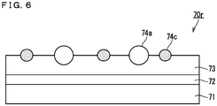
- the ink ribbon 7 includes the back surface part 70r.
- Fig. 6 is a section view of the back surface part 70r included in the ink ribbon 7.
- the upper surface of the back surface part 70r is the surface brought into contact with the thermal head 5 when the printing process P is performed. Note that, below the back surface part 70r, a not-shown transferred material (for example, the dye 7y) is provided below the back surface part 70r.
- the back surface part 70r includes a substrate layer 71, a primer layer 72, and a binder layer 73.
- the binder layer 73 is formed by resin.
- a plurality of lubricating components 74a and a plurality of cleaning components 74c are applied to the front surface of the binder layer 73.
- the front surface of the binder layer 73 is the back surface of the ink ribbon 7.
- the lubricating components 74a are solid.
- the normal temperature environment is, for example, an environment where the temperature is less than 40 degrees.
- the thermal head 5 heating the lubricating components 74a the lubricating components 74a are molten.
- the lubricating components 74a are characterized in that the meltage thereof becomes greater as the quantity of heat applied to the lubricating components 74a is greater.
- the lubricating components 74a are a material that functions as, for example, a lubricant.
- the cleaning components 74c are, for example, talc.
- the state where the ink ribbon 7 being conveyed is in contact with the thermal head 5 is also referred to as the "ribbon contact state”.
- the ribbon contact state friction generated between the thermal head 5 and the ink ribbon 7 is also referred to as the "head friction”.
- a coefficient based on the head friction is also referred to as the “friction coefficient Fc" or "Fc”.
- the head friction is greater as a value of friction coefficient Fc is greater.
- the head friction becomes small.
- the cleaning components 74c prevent fragments occurring at the upper surface of the back surface part 70r from attaching to the thermal head 5.
- an image to be formed on the recording paper 6 by the printing process P is also referred to as the "subject image”.
- each of the value of a plurality of pixels forming the subject image is also referred to as the "print density Dn" or "Dn”.
- the heat quantity Hq0 is a heat quantity with which a color dye does not sublime when heat of the heat quantity Hq0 is applied to the color dye in the above-described transfer process.
- the color dye is one of the dyes 7y, 7m, 7c.
- Fig. 7 is a diagram showing the relationship between the friction coefficient Fc and the print density Dn.
- the vertical axis indicates the friction coefficient Fc.
- the horizontal axis indicates the print density Dn.
- the print density Dn is represented by a numerical value of 8 bits. That is, the print density Dn is represented by 0 to 255. In this case, the minimum value Mn of the print density Dn is 0. The maximum value Mx of the print density Dn is 255.
- the print density Dn that represents the minimum value Mn is the density that corresponds to the heat quantity Hq0.
- the magnitude of the head friction differs depending on the magnitude of the print density Dn. Specifically, as the print density Dn is closer to the minimum value Mn, the value of the friction coefficient Fc is greater. That is, as the print density Dn is closer to the minimum value Mn, the head friction is greater.
- the meltage of the lubricating components 74a is very small in the case where heat of the heat quantity Hq0 corresponding to the print density Dn representing the minimum value Mn is applied to the ink ribbon 7. Accordingly, the head friction is great in the state where heat of the heat quantity Hq0 is applied to the ink ribbon 7.
- any attached substance existing on the thermal head 5 can be removed. Thus, cleaning of the thermal head 5 can be performed.
- the attached substance is, for example, fragments of the ink ribbon 7 occurring from the past printing process P. Further, the attached substance is, for example, dust, waste or the like.
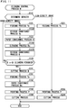
- Fig. 8 is a flowchart of the cleaning control process according to the first embodiment of the present invention.
- an image represented by the image data D1 is also referred to as the "subject image".
- the subject image is an image to be formed on the recording paper 6.
- the subject image is formed by a plurality of pixels.
- the subject image is classified into a high-density image and a low-density image.
- the density of the subject image is also referred to as the "image density".
- the image density is, as an example, the average value of the values of a plurality of pixels forming the subject image.
- Step S110 a density determination is made. Firstly, the calculation unit 21a of the control unit 21 calculates the image density of the subject image. Then, the control unit 21 determines whether or not the image density is greater than a predetermined reference density.
- the reference density is, for example, a value about 0.5 times as great as the maximum value Mx of the above-described print density Dn.
- each of the pixels of the subject image is expressed by a value from 0 to 255.
- the maximum value Mx is 255
- the reference density is, for example, 127.
- the reference density is not limited to, for example, a value about 0.5 times as great as the maximum value Mx.
- the reference density may be a value included in a range from a value 0.3 times to 0.7 times as great as the maximum value Mx.
- control unit 21 determines that the subject image is a high-density image, and the process transits to Step S121.
- the control unit 21 determines that the subject image is a low-density image, and the process transits to Step S221 which will be described later.
- the position where the above-described transfer process is performed on the transferred material is also referred to as the "printing start position".
- Step S121 a feeding process Ye is performed.
- the feeding process Ye the feeding of the dye 7y is performed.
- the conveyance unit 40 conveys the ink ribbon 7 so that the position of the dye 7y is set to the printing start position.
- the conveyance of the ink ribbon 7 by the conveyance unit 40 is performed based on the detection state of the mark MK1s of the sensor SN10 (the sensors SN1, SN2).
- Step S124 a cleaning process N is performed.
- the cleaning process N is a process of performing cleaning of the thermal head 5.
- the cleaning process N is performed using the entire transfer region Rt1 of the transferred material (the dye 7y). That is, the thermal printer performs the cleaning process N using the entire transfer region Rt1 of the ink ribbon 7.
- the state of the platen roller 15 is set to the above-described platen contact state.
- the above-described ribbon conveyance process, the above-described paper conveyance process and a transfer process N are simultaneously performed as to the dye 7y.
- the ink ribbon 7 conveys the ink ribbon 7 in the forward conveyance direction (the -X direction) while the conveyance unit 40 is in contact with the thermal head 5.
- the thermal head 5 applies heat of the above-described heat quantity Hq0 to the ink ribbon 7 in accordance with control of the printing control unit 22.
- the heat quantity Hq0 is the heat quantity with which the color dye (for example, the dye 7y) does not sublime.
- the thermal head 5 applies heat of the heat quantity Hq0 to the entire transfer region Rt1 of the dye 7y. As described above, the head friction is great in the state where the heat of the heat quantity Hq0 is applied to the ink ribbon 7.
- the above-described attached substance existing on the thermal head 5 can be removed. That is, cleaning of the thermal head 5 can be performed with the ink ribbon 7. Accordingly, the above-described heat quantity Hq0 is the heat quantity for performing cleaning of the thermal head 5.
- the ink ribbon 7 has a function of performing cleaning of the thermal head 5 by being heated.
- Step S124r a re-feeding process Ye is performed.
- the state of the platen roller 15 is set to the above-described platen non-contact state.
- the ink ribbon 7 is rewound.
- the conveyance unit 40 conveys the ink ribbon 7 in the reverse conveyance direction (the X direction) so that the position of the sensor SN10 is set to the position on the forward conveyance direction (-X direction) side relative to the mark MK1s corresponding to the dye 7y.
- the conveyance roller pair 13 conveys the recording paper 6 in the paper reverse conveyance direction (X direction) by the shift amount of the ink ribbon 7.
- the above-described feeding process Ye is performed.
- the feeding of the dye 7y is performed.
- Step S130 the above-described printing process P is performed. Note that, before the printing process P is performed, the state of the platen roller 15 is set to the above-described platen contact state. By the printing process P, the dyes 7y, 7m, 7c and the protective material 7op are transferred in order onto the image forming region of the recording paper 6. Thus, the above-described printed article is produced at the end of the recording paper 6.
- Step S190 a cutting process is performed.
- the recording paper 6 including the printed article is conveyed by a predetermined length.
- the cut part Ct1 cuts the recording paper 6 so that the printed article is separated from the recording paper 6.
- the ejection mechanism (not shown), the printed article is ejected from the thermal printer 100.
- the cleaning control process ends.
- Step S110 when it is determined that the subject image is a low-density image in Step S110, the process transits to Step S221.
- Step S221 similarly to Step S121, the above-described feeding process Ye is performed.
- the above-described printing process P (S230) and the above-described cutting process (S290) are performed.
- the cleaning process N is not performed. That is, in the cleaning control process, when the image density is greater than the reference density, the thermal printer 100 performs the cleaning process N. Further, in the cleaning control process, the thermal printer 100 performs the cleaning process N before performing the printing process P.
- the thermal printer 100 uses the ink ribbon 7 having a function of cleaning the thermal head 5 by being heated.
- the thermal printer 100 performs the cleaning process N of cleaning the thermal head 5.
- the thermal head 5 applies, to the ink ribbon 7, heat of a heat quantity with which heat quantity the dye 7y applied onto the ink ribbon 7 does not sublime and with which cleaning is performed.
- cleaning of the thermal head can be performed.
- cleaning of the thermal head 5 is performed using the back surface of the ink ribbon 7. Accordingly, cleaning of the thermal head 5 can be performed without the necessity of attaching a cassette head cleaner including a cleaning sheet to the thermal printer.
- the above-described density determination is a method of comparing the average value of the values of a plurality of pixels forming an image against the reference density, the present invention is not limited thereto.
- the density determination may be made according to other method so long as the cleaning effect is expected.
- the density determination for example, whether or not the subject image is an image having a specific density distribution may be determined. Further, in the density determination, for example, whether or not the subject image is an image having a high-density region in the extending direction of the thermal head 5 may be determined.
- region used in the cleaning process according to the present embodiment is the transfer region Rt1 of the dye 7y
- the present invention is not limited thereto.
- the region used in the cleaning process may be the transfer region Rt1 of the dye 7m, the transfer region Rt1 of the dye 7c, the transfer region Rt1 of the protective material 7op or the like.
- the region used in the cleaning process may be all of the transfer regions Rt1 of the four transferred materials (the dyes 7y, 7m, 7c and the protective material 7op), respectively. Further, the cleaning process may be repeatedly performed using the transfer region Rt1 of each of the transferred materials.
- the thermal printer 100 makes the density determination in the present embodiment
- the present invention is not limited thereto.
- An apparatus other than the thermal printer 100 may perform the density determination so long as the apparatus is capable of processing image data.
- the information processing apparatus 200 may make the density determination.
- the information processing apparatus 200 may make the density determination, and inform the thermal printer 100 whether or not execution of the cleaning process is necessary.
- the reason why the density determination is made in the above-described manner is described.
- the meltage of the lubricating components 74a on the back surface of the ink ribbon 7 is great.
- the molten lubricating components 74a may be highly likely to attach to the thermal head 5 as fragments (an attached substance).
- the cleaning components 74c may fail to completely remove the fragments.
- the cleaning process N when the subject image is a high-density image, the cleaning process N is performed.
- the conveyance unit 40 conveys the ink ribbon 7 in the forward conveyance direction while the ink ribbon 7 is in contact with the thermal head 5. Thereafter, the conveyance unit 40 conveys the ink ribbon 7 in the reverse conveyance direction.
- the time taken for the printing increases.
- cleaning process N being performed, cleaning of the thermal head 5 can be effectively performed using the entire transfer region Rt1 of the transferred material (the dye 7y).
- the cleaning process N is performed in the case where the subject image is a high-density image. Accordingly, an increase in time taken for a printing process can be minimized. Further, in the case where the fragments of the ink ribbon are attached to the thermal head 5 due to manufacturing variations of the ink ribbon or the like also, cleaning of the thermal head 5 can be surely executed.
- the cleaning of the thermal head 5 can be performed without the necessity of attaching a dedicated cleaning cassette including a cleaning sheet to the thermal printer 100 as in the conventional case. Accordingly, the present embodiment can save users' time and trouble in maintenance of the thermal head 5. Further, high-quality printing can be performed. Accordingly, a high-quality printed article free from scratches due to an ink fragments, waste or the like can be obtained.
- the related structure A suffers from a problem that it necessitates the trouble of, every time cleaning of the thermal head 5 is required, removing the ink ribbon from the thermal printer and thereafter attaching the cassette head cleaner to the thermal printer.
- the thermal printer 100 according to the present embodiment is structured as described above. Accordingly, the thermal printer 100 according to the present embodiment can solve the above-described problem.
- the region in the ink ribbon 7 other than the transfer region Rt1 is also referred to as the "non-transfer region".
- cleaning is performed using a non-transfer region (hereinafter also referred to as the "structure CtA").
- the thermal printer in the structure CtA is the thermal printer 100.
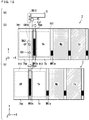
- FIG. 9 is a flowchart of the cleaning control process A according to a second embodiment of the present invention.
- Fig. 10 is a diagram for describing part of the cleaning control process A according to the second embodiment of the present invention.
- Part (a) in Fig. 10 is a diagram mainly showing the thermal head 5 and the sensor SN10.
- Part (b) in Fig. 10 and part (c) in Fig. 10 are each a plan view for describing part of the cleaning control process A.
- a process denoted by the step number identical to that in Fig. 8 is the process identical to that described in the first embodiment and, therefore, a detailed description thereof will not be repeated. In the following, a description will be given mainly of the difference from the first embodiment.
- Step S110 is performed.
- the process transits to Step S121A.
- Step S121A a k-th feeding process is performed.
- "k" is a natural number.
- the initial value of k is 1.
- feeding of a k-th transferred material is performed.
- the k-th transferred material is the dye 7y. In this case, feeding of the dye 7y being the first transferred material is performed.
- cleaning is performed using regions Rga, Rgb.
- the region Rga is a region between two transfer regions Rt1 respectively included in adjacent two transferred materials in the ink ribbon 7.
- Each of the regions Rga, Rgb is a region not used for printing.
- the region Rga is the region between the transfer region Rt1 of the protective material 7op and the transfer region Rt1 of the dye 7y in the ink ribbon 7.
- the region Rga is adjacent to the transfer region Rt1 of the k-th transferred material in the forward conveyance direction (the -X direction).
- the region Rga adjacent to the transfer region Rt1 of the dye 7y includes the mark MK1s.
- the region Rgb adjacent to the transfer region Rt1 of the dye 7y includes the mark MK1a.
- the region Rgb is the region between the transfer region Rt1 of the dye 7y and the transfer region Rt1 of the dye 7m in the ink ribbon 7.
- the region Rgb is adjacent to the transfer region Rt1 of the k-th transferred material in the reverse conveyance direction (the X direction).
- the size of the region Rga is identical to the size of the region Rgb.
- the length in the ribbon conveyance direction (the X-axis direction) of each of the region Rga and the region Rgb is also referred to as the "length Lsc".
- Step S122 a k-th reverse conveyance process is performed.
- the k-th reverse conveyance process is a process of conveying the k-th transferred material in the reverse conveyance direction (the X direction). That is, in the k-th reverse conveyance process, the ink ribbon 7 is rewound. Specifically, in the k-th reverse conveyance process, the conveyance unit 40 conveys the ink ribbon 7 in the reverse conveyance direction (the X direction), so that the leading end (the left end) of the region Rga adjacent to the transfer region Rt1 of the k-th transferred material is set to the heating position LC1.
- Step S124A a cleaning process Aa is performed.
- the cleaning process Aa firstly, the state of the platen roller 15 is set to the above-described platen contact state. Then, the ribbon conveyance process Aa, the paper conveyance process Aa, and the transfer process Aa are simultaneously performed on the region Rga adjacent to the transfer region Rt1 of the k-th transferred material.
- the conveyance unit 40 conveys the ink ribbon 7 in the forward conveyance direction (the -X direction) by the length Lsc while the ink ribbon 7 is in contact with the thermal head 5.
- the conveyance roller pair 13 conveys the recording paper 6 in the paper forward conveyance direction (the -X direction) by the length Lsc.
- the thermal head 5 applies heat of the above-described heat quantity Hq0 to the ink ribbon 7 in accordance with control of the printing control unit 22. Specifically, in the transfer process Aa, the thermal head 5 applies heat of the heat quantity Hq0 to the entire region Rga.
- Step S125 a k-th printing process is performed.
- the k-th printing process is a process of transferring the k-th transferred material onto the image forming region of the recording paper 6. Further, the k-th printing process is also a process of selectively transferring the dyes 7y, 7m, 7c and the protective material 7op onto the recording paper 6.
- Step S124A the cleaning process Aa
- the thermal printer 100 performs the cleaning process Aa before performing the k-th printing process.
- Step S126 a cleaning process Ab is performed.
- the cleaning process Ab the above-described ribbon conveyance process Aa, the above-described paper conveyance process Aa, and a transfer process Ab are simultaneously performed on the region Rgb of the ink ribbon 7.
- the thermal head 5 applies heat of the above-described heat quantity Hq0 to the ink ribbon 7 in accordance with control of the printing control unit 22 over the period in which the ink ribbon 7 and the recording paper 6 are conveyed. Specifically, in the transfer process Ab, the thermal head 5 applies heat of the heat quantity Hq0 to the entire region Rgb.
- Step S127 the control unit 21 determines whether the value of k falls within a range from 1 to 3 inclusive.
- Step S127A the process transits to Step S127A.
- Step S128 the process transits to Step S128.
- Step S126 As seen in a plan view (the XY-plane), the sensor SN10 is at a position where the sensor SN10 cannot normally detect the mark MK1a corresponding to the second transferred material (the dye 7m). Accordingly, the process of the Step S127A is performed.
- Step S127A a feeding-purpose reverse conveyance process is performed.
- the ink ribbon 7 is rewound so that feeding of the transferred material subsequent to the k-th transferred material is performed.
- the state of the platen roller 15 is set to the above-described platen non-contact state.
- the conveyance unit 40 conveys the ink ribbon 7 in the reverse conveyance direction (the X direction), so that the position of the sensor SN10 is set on the forward conveyance direction (-X direction) side relative to the mark MK1a corresponding to the (k + 1)-th transferred material (for example, the dye 7m).
- Step S1208 the control unit 21 determines whether or not k is 4. When k is 4, the printing process of the fourth transferred material (the protective material 7op) is finished. When YES in Step S128, the process transits to Step S190. On the other hand, when NO in Step S128, the value of k is incremented by 1 (S128A), and again the process of Step S121A is performed.
- Step S121A a process for feeding the dye 7m being the second transferred material is performed.
- Step S121A the conveyance of the ink ribbon 7 by the conveyance unit 40 is performed based on the detection state of the sensor SN10 (the sensors SN1, SN2) as to the mark MK1a corresponding to the dye 7m.
- Step S121A to S128A are repeatedly performed until the determination result is YES in Step S128.
- the dyes 7y, 7m, 7c, and the protective material 7op are transferred in order onto the image forming region.
- cleaning of the thermal head 5 is performed using the regions Rga, Rgb respectively corresponding to the transferred materials. That is, the thermal printer 100 performs the cleaning process Aa using the region Rga being a non-transfer region. Further, the thermal printer 100 performs the cleaning process Ab using the region Rgb being a non-transfer region. Still further, in the cleaning control process A, the cleaning process Aa is performed before each of a plurality of (three times of) k-th printing processes respectively for transferring a plurality of types of the dyes (the dyes 7y, 7m, 7c) on the recording paper 6 is performed.
- Step S190 is performed, and the cleaning control process A ends.
- Step S110 when it is determined that the subject image is a low-density image, similarly to the first embodiment, the processes of Steps S221, S230, S290 are performed.
- the present embodiment before transfer of each of the transferred materials is performed, cleaning of the thermal head 5 is performed. Accordingly, the present embodiment also exhibits the effect similar to that exhibited by the first embodiment.
- the present invention is not limited thereto.
- the width of each of the regions Rga, Rgb is fully long, the process of rewinding the ink ribbon performed before the process of transferring the transferred materials can be dispensed with.
- both the regions Rga, Rgb corresponding to the transferred materials are used in the cleaning process of the present embodiment, the present invention is not limited thereto.
- just one of the regions Rga, Rgb respectively corresponding to the transferred materials may be used.
- at least one of the regions Rga, Rgb corresponding to just a single transferred material may be used.
- the regions Rga, Rgb corresponding to a plurality of transferred materials in combination may be used.
- cleaning is performed using the non-transfer region for a plurality of times (hereinafter also referred to as the "structure CtB").
- the thermal printer in the structure CtB is the thermal printer 100.
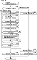
- FIG. 11 is a flowchart of the cleaning control process B according to a third embodiment of the present invention.
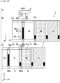
- Fig. 12 is a diagram showing part of the cleaning control process B according to the third embodiment of the present invention.
- Part (a) in Fig. 12 is a diagram that mainly shows the thermal head 5 and the sensor SN10.
- Part (b) in Fig. 12 and part (c) in Fig. 12 are each a plan view for describing part of the cleaning control process B.
- part (b) in Fig. 12 shows the region Rga described in the second embodiment.
- the region Rga according to the present embodiment is the region between the transfer region Rt1 of the protective material 7op and the transfer region Rt1 of the dye 7y in the ink ribbon 7. That is, the region Rga according to the present embodiment is a region adjacent to the transfer region Rt1 of the dye 7y.
- the region Rga is a region not used in printing. Further, the region Rga includes the mark MK1s.
- a process denoted by the step number identical to that in Fig. 8 is the process identical to that described in the first embodiment and, therefore, a detailed description thereof will not be repeated. In the following, a description will be given mainly of the difference from the first embodiment.
- Step S110 is performed.
- the process transits to Step S121.
- Step S121 similarly to the first embodiment, the feeding process Ye is performed.
- Step S122B the reverse conveyance process Ye is performed.
- the ink ribbon 7 is rewound.
- the conveyance unit 40 conveys the ink ribbon 7 in the reverse conveyance direction (the X direction), so that the leading end (the left end) of the region Rga adjacent to the transfer region Rt1 of the dye 7y is set to the heating position LC1.
- the leading end (the left end) of the region Rga is the trailing end (the right end) of the transfer region Rt1 of the protective material 7op.
- the trailing end (the right end) of the transfer region Rt1 of the protective material 7op is set to the heating position LC1.
- Step S123 the paper conveyance process B is performed.
- the recording paper 6 is conveyed in the ejecting direction.
- the conveyance roller pair 13 conveys the recording paper 6 in the paper reverse conveyance direction, so that the position of the leading end of the image forming region of the recording paper 6 is positioned on the paper reverse conveyance direction (X direction) side relative to the heating position LC1 by the above-described length Lsc.
- the leading end of the image forming region of the recording paper 6 is the end corresponding to the position in the image forming region where transfer of the transferred material is started.
- the position of the leading end of the image forming region of the recording paper 6 is set to the left end in the transfer region Rt1 of the dye 7y in part (b) in Fig. 12 .
- Step S124B a cleaning process Ba is performed.
- the cleaning process Ba firstly, the state of the platen roller 15 is set to the above-described platen contact state. Then, the above-described ribbon conveyance process Aa, the above-described paper conveyance process Aa, and the above-described transfer process Aa are simultaneously performed on the region Rga adjacent to the transfer region Rt1 of the dye 7y. As described above, the region Rga is a region not used in printing.
- the conveyance unit 40 conveys the ink ribbon 7 in the forward conveyance direction (the -X direction) by the length Lsc while the ink ribbon 7 is in contact with the thermal head 5.
- the conveyance roller pair 13 conveys the recording paper 6 in the paper forward conveyance direction (the -X direction) by the length Lsc.
- the thermal head 5 applies heat of the above-described heat quantity Hq0 to the ink ribbon 7 in accordance with control of the printing control unit 22. Specifically, in the transfer process Aa, the thermal head 5 applies heat of the heat quantity Hq0 to the entire region Rga.
- Step S127B the reverse conveyance process B is performed.
- the ink ribbon 7 is rewound so that feeding of the dye 7y can be performed.
- the conveyance unit 40 conveys the ink ribbon 7 in the reverse conveyance direction, so that the position of the sensor SN10 as seen in a plan view (the XY-plane) is set to the position on the forward conveyance direction (-X direction) side relative to the mark MK1s corresponding to the dye 7y.
- the conveyance roller pair 13 conveys the recording paper 6 in the paper reverse conveyance direction (the X direction) by the shift amount of the ink ribbon 7.
- Step S129 whether or not the cleaning processes for s-times are finished is determined. Specifically, the control unit 21 determines whether or not the cleaning process Ba has been performed for s times. "s" is a natural number equal to or greater than 2. For example, s is an integer falling within a range from 2 to 5 inclusive.
- Step S141 the process transits to Step S141.
- Step S129 again the process of Step S121 is performed.
- the cleaning control process B the processes from Steps S121 to S127B are repeatedly performed until the determination result is YES in Step S129.
- the cleaning process Ba is repeatedly performed. That is, the thermal printer 100 repeatedly performs the cleaning process Ba using the region Rga being a non-transfer region.
- the paper cleaning part is the portion in the recording paper 6 other than the image forming region. Specifically, the paper cleaning part is the portion, in the recording paper 6, being in contact with the region Rga of the ink ribbon 7 in the period in which the cleaning process Ba is performed.
- Step S141 the cutting process B is performed.
- the cutting process B the recording paper 6 including the paper cleaning part is conveyed by a predetermined length.
- the cut part Ct1 cuts the recording paper 6 so that the paper cleaning part is separated from the recording paper 6.
- an ejection mechanism not shown, the paper cleaning part is ejected from the thermal printer 100.
- Step S151 similarly to the first embodiment, the feeding process Ye is performed.
- Step S152 the paper conveyance process Ba is performed.
- the conveyance roller pair 13 conveys the recording paper 6 so that the position of the leading end of the image forming region of the recording paper 6 is set to the heating position LC1.
- the state of the platen roller 15 is set to the above-described platen contact state and, similarly to the first embodiment, the printing process P (S160) and the cutting process (S190) are performed.
- Step S110 when it is determined that the subject image is a low-density image, similarly to the first embodiment, the processes of Steps S221, S230, S290 are performed.
- the cleaning process Ba is not performed. That is, in the cleaning control process B, when the image density is greater than the reference density, the thermal printer 100 repeatedly performs the cleaning process Ba. Further, in the cleaning control process B, the thermal printer 100 performs the cleaning process Ba before performing the printing process P.
- the cleaning process Ba is repeatedly performed. Accordingly, the present embodiment also exhibits the effect similar to that exhibited by the first embodiment.
- the processes from Steps S121 to S141 including the cleaning process Ba may be performed before the process for transferring each of the transferred materials. Further, the processes from Steps S121 to S141 including the cleaning process Ba may be performed after the printing process P ends.
- Fig. 13 is a block diagram showing the characteristic functional structure of a thermal printer BL10.
- the thermal printer BL10 corresponds to the thermal printer 100. That is, Fig. 13 is a block diagram showing, out of the functions of the thermal printer BL10, the main functions relating to the present invention present.
- the thermal printer BL10 Using an ink ribbon having a function of performing cleaning of the thermal head by being heated, the thermal printer BL10 performs a printing process for forming an image on recording paper.
- the thermal printer BL10 functionally includes a thermal head BL1 and a printing control unit BL2.
- the thermal head BL1 has a function of emitting heat.
- the thermal head BL1 corresponds to the thermal head 5.
- the printing control unit BL2 controls the thermal head BL1.
- the printing control unit BL2 corresponds to the printing control unit 22.
- the thermal printer BL10 performs a cleaning process of performing cleaning of the thermal head BL1.
- the thermal head BL1 applies, to the ink ribbon, heat of a heat quantity with which the dye applied onto the ink ribbon does not sublime and with which the cleaning is performed.
- the present invention is not limited to the embodiments.
- the present invention includes any modification of the embodiments that the person skilled in the art may arrive at, within a range not departing from the spirit of the present invention. That is, within the scope of the present invention, the embodiments may be freely combined, modified, or omitted as appropriate.
- the thermal printer 100 may not necessarily include all the constituents shown in the drawings. That is, the thermal printer 100 should include the minimum constituents with which the effect of the present invention can be realized.
- the present invention can be realized as a cleaning method in which the operations of the characteristic structures of the thermal printer 100 are realized by steps.
- the present invention is not limited thereto.
- an ink ribbon not provided with the protective material 7op may be used.
Landscapes
- Electronic Switches (AREA)
- Impression-Transfer Materials And Handling Thereof (AREA)
Abstract
Description
- The present invention relates to a thermal printer having a function of cleaning a thermal head.
- With a thermal printer, it is required to periodically perform cleaning of a thermal head.
Patent Document 1 discloses a structure for performing cleaning of a thermal head (hereinafter referred to as the "related structure A"). In the related structure A, a cassette head cleaner including a cleaning sheet is attached to a thermal printer, to perform cleaning of the thermal head. Thus, any attached substance deposited on the thermal head is removed. - Patent Document 1: Japanese Patent Application Laid-Open No.
2016-193570 - However, with the related structure A, in performing cleaning of the thermal head, it is required to remove an ink ribbon (an ink ribbon cassette) from the thermal printer, and thereafter attach a cassette head cleaner to the thermal printer. Accordingly, there exists a problem that, in performing cleaning of the thermal head, a cleaning-dedicated cassette head cleaner must be provided.
- The present invention has been made to solve such a problem, and an object thereof is to provide a thermal printer with which cleaning of a thermal head can be performed without the necessity of using a cassette head cleaner.
- In order to achieve the object, a thermal printer according to one aspect of the present invention performs a printing process for forming an image on recording paper using an ink ribbon having a function of performing cleaning of a thermal head by being heated. The thermal printer includes the thermal head having a function of emitting heat, and a printing control unit controlling the thermal head. The thermal printer performs a cleaning process of performing the cleaning of the thermal head. In the cleaning process, in accordance with control of the printing control unit, the thermal head applies, to the ink ribbon, heat of a heat quantity with which a dye applied onto the ink ribbon does not sublime and with which the cleaning is performed.
- According to the present invention, the thermal printer uses an ink ribbon having a function of performing cleaning of a thermal head by being heated. The thermal printer performs a cleaning process of performing the cleaning of the thermal head. In the cleaning process, the thermal head applies, to the ink ribbon, heat of a heat quantity with which a dye applied onto the ink ribbon does not sublime and with which the cleaning is performed. Thus, cleaning of the thermal head can be performed without the necessity of using a cassette head cleaner.
- The object, characteristics, aspects, and advantages of the present invention will become more apparent from the following detailed description and accompanying drawings.
-
-
Fig. 1 is a block diagram showing the schematic structure of a thermal printer according to a first embodiment of the present invention. -
Fig. 2 is a diagram mainly showing a mechanical structure for performing printing in the thermal printer according to the first embodiment of the present invention. -
Fig. 3 is a diagram for describing part of an ink ribbon. -
Fig. 4 is a diagram mainly showing a mechanism that conveys the ink ribbon in the thermal printer according to the first embodiment of the present invention. -
Fig. 5 is a diagram for describing the structure of an ink conveyance unit. -
Fig. 6 is a section view of a back surface part included in the ink ribbon. -
Fig. 7 is a diagram showing the relationship between a friction coefficient and a print density. -
Fig. 8 is a flowchart of a cleaning control process according to the first embodiment of the present invention. -
Fig. 9 is a flowchart of a cleaning control process A according to a second embodiment of the present invention. -
Fig. 10 is a diagram for describing part of the cleaning control process A according to the second embodiment of the present invention. -
Fig. 11 is a flowchart of a cleaning control process B according to a third embodiment of the present invention. -
Fig. 12 is a diagram for describing part of the cleaning control process B according to the third embodiment of the present invention. -
Fig. 13 is a block diagram showing the characteristic functional structure of the thermal printer. - In the following, with reference to the drawings, a description will be given of embodiments of the present invention. In the drawings referred to hereinafter, identical constituents are denoted by an identical reference character. The constituents denoted by an identical reference character have identical name and functions. Accordingly, a detailed description of part of the constituents denoted by an identical reference character may be omitted.
- Note that, the dimension, material, shape, and relative position of constituents exemplarily shown in the embodiments may be modified as appropriate depending on the structure, various conditions and the like of the apparatus to which the present invention is applied.
-
Fig. 1 is a block diagram showing the schematic structure of athermal printer 100 according to a first embodiment of the present invention. Note that, for the sake of convenience,Fig. 1 also shows aninformation processing apparatus 200 not included in thethermal printer 100. - While details will be described later, the
thermal printer 100 performs a printing process P for forming an image onrecording paper 6, which will be described later, using anink ribbon 7, which will be described later. Theinformation processing apparatus 200 is an apparatus that controls thethermal printer 100. Theinformation processing apparatus 200 is, for example, a PC (Personal Computer). Theinformation processing apparatus 200 is operated by the user. - When the user performs a printing execution operation on the
information processing apparatus 200, theinformation processing apparatus 200 transmits a print instruction and image data D1 to thethermal printer 100. The printing execution operation is an operation for causing thethermal printer 100 to execute the printing process P. Further, the print instruction is an instruction for causing thethermal printer 100 to execute the printing process P. The image data D1 is data of an image to be printed on therecording paper 6, which will be described later. - With reference to
Fig. 1 , thethermal printer 100 includes astorage unit 10, acontrol unit 20, acommunication unit 30, and athermal head 5. - The
storage unit 10 is memory that stores various types of data, programs and the like. Thestorage unit 10 is, for example, structured by non-volatile memory and volatile storage memory. Thestorage unit 10 stores, for example, a control program for controlling thethermal printer 100, data relating to control of printing, image data, print data, various types of data, various types of set values, various types of initial values and the like. - The
thermal head 5 has a function of emitting heat. While details will be described later, thethermal head 5 emits heat in accordance with control of thecontrol unit 20. - While details will be described later, the
control unit 20 performs various processes on the units of thethermal printer 100. Thecontrol unit 20 performs the various processes according to a control program. Thecontrol unit 20 is, for example, a processor such as a CPU (Central Processing Unit). - The
control unit 20 includes acontrol unit 21, aprinting control unit 22, and amachine control unit 23. All or part of thecontrol unit 21, theprinting control unit 22, and themachine control unit 23 are structured by a signal processing circuit structured by a hardware electric circuit. Note that, all or part of thecontrol unit 21, theprinting control unit 22, and themachine control unit 23 may be a program module executed by thecontrol unit 20. - While details will be described later, the
control unit 21 mainly performs a process of controlling the entirethermal printer 100. Further, thecontrol unit 21 makes access to thestorage unit 10, and reads out data and the like stored in thestorage unit 10 as necessary. - The
control unit 21 includes acalculation unit 21a. Thecalculation unit 21a is described in the following. Thecalculation unit 21a is a program module executed by thecontrol unit 21. In other words, thecalculation unit 21a is realized by thecontrol unit 21 performing various types of processes in accordance with a software program stored in memory or the like. Note that, thecalculation unit 21a may be structured by a signal processing circuit structured by a hardware electric circuit that performs the various types of processes. - The
printing control unit 22 controls thethermal head 5. While details will be described later, theprinting control unit 22 performs a process for performing printing, using thethermal head 5. While details will be described later, themachine control unit 23 controls a mechanical structure included in the thermal printer 100 (hereinafter also referred to as the "mechanical structure") in accordance with control of thecontrol unit 21. That is, thecontrol unit 21 controls the mechanical structure via themachine control unit 23. - The
communication unit 30 communicates with theinformation processing apparatus 200 and thecontrol unit 21. The print instruction and the image data D1 transmitted by theinformation processing apparatus 200 are transmitted to thecontrol unit 21 via thecommunication unit 30. Thecommunication unit 30 establishes communication using, for example a USB (Universal Serial Bus) interface. - According to the received print instruction, the
control unit 21 generates print data using the received image data D1. The print data is control data for printing an image represented by image data D1 on therecording paper 6. Thecontrol unit 21 transmits the print data to theprinting control unit 22. According to the print data, theprinting control unit 22 controls the quantity of heat emitted by thethermal head 5. Thus, the image represented by the image data D1 is printed on therecording paper 6. -
Fig. 2 is a diagram mainly showing the mechanical structure for performing printing in thethermal printer 100 according to the first embodiment of the present invention. Note that,Fig. 2 shows the state whereroll paper 6r and anink ribbon 7 are attached to thethermal printer 100. Theroll paper 6r is formed byelongated recording paper 6 being rolled up. - The
ink ribbon 7 is an elongated sheet. By one end of theink ribbon 7 being rolled up, anink ribbon roll 7r is formed. Theink ribbon roll 7r is a roll that supplies the ink ribbon 7 (hereinafter also referred to as the "supply-side roll"). - By other end of the
ink ribbon 7 being rolled up, an ink ribbon roll 7rm is formed. The ink ribbon roll 7rm is a roll for taking up the ink ribbon 7 (hereinafter also referred to as the "take-up-side roll"). - The
thermal printer 100 is structured so that the ink ribbon rolls 7r, 7rm are removably attached to thethermal printer 100. - While details will be described later, the
thermal printer 100 performs a printing process P for forming an image on therecording paper 6. While details will be described later, the printing process P is a process for transferringdyes recording paper 6. -
Fig. 3 is a diagram for describing part of theink ribbon 7. Note that,Fig. 3 also shows sensors SN1, SN2 which will be described later. InFig. 3 , an X direction and a Y direction are perpendicular to each other. The X direction and the Y direction appearing in the subsequent drawings are also perpendicular to each other. - Hereinafter, a direction including the X direction and a direction opposite to the X direction (-X direction) is also referred to as the "X-axis direction". Further, in the following, a direction including the Y direction and a direction opposite to the Y direction (-Y direction) is also referred to as the "Y-axis direction". Further, hereinafter, a plane including the X-axis direction and the Y-axis direction is also referred to as the "XY-plane".
- With reference to
Fig. 3 , theink ribbon 7 is provided with a plurality of unit regions R10 each includingdyes ink ribbon 7. That is, onto theink ribbon 7, thedyes dyes recording paper 6. - Each of the
dyes recording paper 6 by being heated by thethermal head 5. For example, thedye 7y is a first transferred material. That is, thedye 7y is the material that is firstly transferred onto therecording paper 6 in the printing process P. Further, for example, the protective material 7op is a fourth transferred material. - Each of the
dyes recording paper 6 being the target of transfer. Specifically, thedyes dyes - The protective material 7op is a material for protecting the colors transferred onto the recording paper 6 (overcoat). Specifically, the protective material 7op is a material for protecting an image formed by the
dyes recording paper 6. Hereinafter, the protective material 7op is also referred to as the "OP material". - Each of the
dyes ink ribbon 7. The transfer region Rt1 is a transfer-source area in each of the transferred materials. Onto the transfer region Rt1 of the color dye, a dye (dyes - Hereinafter, in the
recording paper 6, a region for forming an image is also referred to as an "image forming region". The shape and size of the image forming region are equal to the shape and size of the transfer region Rt1 shown inFig. 3 . Further, hereinafter, the direction in which theink ribbon 7 is conveyed for forming an image at the image forming region of therecording paper 6 is also referred to as the "forward conveyance direction". InFig. 3 , the forward conveyance direction is the -X direction. - Note that, in the printing process P, the
dye 7y is firstly transferred onto the image forming region of therecording paper 6. Thereafter, thedye dye dyes - Hereinafter, the
dye 7y is also referred to as the "transferred material ma1". Further, hereinafter, thedye 7m is also referred to as the "transferred material mb2". Still further, hereinafter, thedye 7c is also referred to as the "transferred material mb3". Still further, hereinafter, the protective material 7op is also referred to as the "transferred material mb4". - In the printing process P, onto the image forming region of the
recording paper 6, the transferred materials ma1, mb2, mb3, mb4 are transferred in order of the transferred materials ma1, mb2, mb3, mb4. Hereinafter, each of the transferred materials mb2, mb3, mb4 is also referred to as the "transferred material mb". The transferred material mb is a transferred material that is transferred secondly and later in the printing process P. - Further, the
ink ribbon 7 is provided with a plurality of marks MK1a and a plurality of marks MK1s. The mark MK1a is a mark for specifying the position of the transferred material mb. Each of the mark MK1a and the mark MK1s is, for example, formed by a black-color material. - The mark MK1a is provided in association with the transferred material mb. Specifically, the mark MK1a is provided at a region on the forward conveyance direction (the -X direction) side relative to the transferred material mb in the
ink ribbon 7, so that the mark MK1a becomes adjacent to the transferred material mb. Here, it is assumed that the transferred material mb is thedye 7m (the transferred material mb2). In this case, as shown inFig. 3 , the mark MK1a is provided at a region on the forward conveyance direction (the -X direction) side relative to thedye 7m in theink ribbon 7, so that the mark MK1a becomes adjacent to thedye 7m. - The mark MK1s is a mark for specifying the position of the
dye 7y (the transferred material ma1) being the first transferred material. The mark MK1s is provided in association with thedye 7y. Specifically, the mark MK1s is provided at the region on the forward conveyance direction (-X direction) side relative to thedye 7y in theink ribbon 7, so that the mark MK1s becomes adjacent to thedye 7y. - With reference again to
Figs. 1 and2 , thethermal printer 100 further includes aconveyance roller pair 13, aplaten roller 15, aconveyance unit 40, a sensor SN10, and a cut part Ct1. -
Fig. 4 is a diagram mainly showing a mechanism that conveys theink ribbon 7 in thethermal printer 100 according to the first embodiment of the present invention (hereinafter also referred to as the "conveyance mechanism"). Part (a) inFig. 4 is a side view of the conveyance mechanism. Note that, in part (a) inFig. 4 , for the sake of easier understanding of the conveyance mechanism, part of the constituents (for example, the ink ribbon roll 7rm) is shown at a position different from the actual position. - In part (a) in
Fig. 4 , the X direction, the Y direction, and the Z direction are perpendicular to each other. In the subsequent drawings also, the X direction, the Y direction, and the Z direction are perpendicular to each other. As described above, a direction including the X direction and a direction opposite to the X direction (the -X direction) is also referred to as the "the X-axis direction". Further, as described above, a direction including the Y direction and a direction opposite to the Y direction (the -Y direction) is also referred to as "the Y-axis direction". Hereinafter, a direction including the Z direction and a direction opposite to the Z direction (the -Z direction) is also referred to as "the Z-axis direction". - Further, as described above, a plane including the X-axis direction and the Y-axis direction is also referred to as "the XY-plane". Hereinafter, a plane including the X-axis direction and the Z-axis direction is also referred to as "the XZ-plane". Further, hereinafter, a plane including the Y-axis direction and the Z-axis direction is also referred to as "the YZ-plane". Part (b) in
Fig. 4 is a plan view of the conveyance mechanism. - With reference to
Figs. 1 ,2 , and4 , theconveyance roller pair 13 is a roller pair for conveying therecording paper 6. Theconveyance roller pair 13 is structured by agrip roller 13a and apinch roller 13b. Thegrip roller 13a rotates by being driven by a rotary driver unit (not shown) such as a motor. - The
platen roller 15 is in contact with therecording paper 6 conveyed by theconveyance roller pair 13. Theplaten roller 15 is provided so as to oppose to part of thethermal head 5. - The
conveyance unit 40 is a mechanism for conveying theink ribbon 7. Theconveyance unit 40 is structured byink conveyance units ink conveyance unit 80 conveys theink ribbon 7 in the forward conveyance direction (the -X direction) in accordance with control of themachine control unit 23. - Hereinafter, an amount by which the
ink ribbon 7 is transferred is also referred to as the "conveyance amount". The conveyance amount is also a distance by which theink ribbon 7 travels. Theink conveyance unit 80 has a function of controlling the conveyance amount of theink ribbon 7 using anencoder 11 which will be described later. - Hereinafter, a direction opposite to the forward conveyance direction is also referred to as the "reverse conveyance direction". In part (a) in
Fig. 4 , the reverse conveyance direction is the X direction. While details will be described later, theink conveyance unit 90 conveys theink ribbon 7 in the reverse conveyance direction (the X direction) in accordance with themachine control unit 23. -
Fig. 5 is a diagram for describing the structure of theink conveyance unit 80. Part (a) inFig. 5 is a diagram showing the structure of theink conveyance unit 80 along the XZ-plane. Part (b) inFig. 5 is a diagram showing the structure of theencoder 11, which will be described later, included in theink conveyance unit 80 along the YZ-plane. - With reference to part (b) in
Fig. 4 andFig. 5 , theink conveyance unit 80 includes anattachment 81, a take-up-side gear 82, amotor gear 83, a motor MT2, and theencoder 11. - The
attachment 81 is fixed to the side surface of the ink ribbon roll 7rm. Themotor gear 83 is a bar-like member. On the outer surface of themotor gear 83, a gear is provided. Themotor gear 83 is attached to the motor MT2. The motor MT2 causes themotor gear 83 to rotate in accordance with control of themachine control unit 23. - The take-up-
side gear 82 is fixed to theattachment 81. Further, the take-up-side gear 82 is provided so as to mesh with the gear at the outer surface of themotor gear 83. Thus, the motor MT2 causes themotor gear 83 to rotate, thereby successfully causing the ink ribbon roll 7rm to rotate via the take-up-side gear 82 and theattachment 81. - As necessary, the motor MT2 exerts control for conveying the
ink ribbon 7 in the forward conveyance direction (the -X direction). Specifically, the motor MT2 causes themotor gear 83 to rotate so that the take-up-side gear 82 rotates in the counterclockwise direction, thereby causing the ink ribbon roll 7rm to rotate in the counterclockwise direction. Thus, theink ribbon 7 is conveyed in the forward conveyance direction (the -X direction). - Note that, in accordance with the rotation of the ink ribbon roll 7rm, the
ink ribbon roll 7r also rotates so that the tension applied to theink ribbon 7 is maintained at a constant value. Accordingly, in accordance with the ink ribbon roll 7rm taking up part of theink ribbon 7, theink ribbon roll 7r supplies theink ribbon 7 by the length of the taken upink ribbon 7. - The
encoder 11 is structured by arotary member 84 and a sensor SN20. Therotary member 84 is a disc-like member. Therotary member 84 is fixed to an end of themotor gear 83. Thus, therotary member 84 rotates in accordance with the rotation of themotor gear 83. Therotary member 84 is provided with a not-shown plurality of slits arranged circularly. - The sensor SN20 has a function of detecting each of the slits of the
rotating rotary member 84. Every time the sensor SN20 detects the slit of therotary member 84, the sensor SN20 transmits a pulse (signal) to thecontrol unit 21 via themachine control unit 23. - Next, a description will be given of the
ink conveyance unit 90. With reference to part (b) inFig. 4 , theink conveyance unit 90 includes anattachment 91, a supply-side gear 92, amotor gear 93, atorque limiter 94, and a motor MT1. - The
attachment 91 is fixed to the side surface of theink ribbon roll 7r. The supply-side gear 92 is fixed to theattachment 91. Note that, to the supply-side gear 92, thetorque limiter 94 for adjusting the rotary force (torque) of theink ribbon roll 7r is provided. A gear is provided at the side surface of the supply-side gear 92. - The
motor gear 93 is attached to the motor MT1. Themotor gear 93 is provided so as to mesh with the gear at the side surface of the supply-side gear 92. The motor MT1 causes themotor gear 93 to rotate in accordance with control of themachine control unit 23. The motor MT1 causes themotor gear 93 to rotate, thereby successfully causing theink ribbon roll 7r to rotate via the supply-side gear 92 and theattachment 91. - As necessary, the motor MT1 exerts control for conveying the
ink ribbon 7 in the reverse conveyance direction (the X direction). Specifically, the motor MT1 causes themotor gear 93 to rotate so that the supply-side gear 92 (theink ribbon roll 7r) rotates in the clockwise direction. Thus, theink ribbon 7 is conveyed in the reverse conveyance direction (the X direction). That is, the operation of the motor MT1 allows the ink ribbon roll 7rm to take up theink ribbon 7. Note that, in accordance with the rotation of theink ribbon roll 7r, the ink ribbon roll 7rm also rotates. Hereinafter, the path along which theink ribbon 7 is conveyed is also referred to as the "conveyance path". - Next, a description will be given of the sensor SN10. The sensor SN10 has a function of detecting the mark MK1a and the mark MK1s while the
ink ribbon 7 is being conveyed by theconveyance unit 40. The sensor SN10 is provided upstream to thethermal head 5 in the conveyance path along which theink ribbon 7 is conveyed. - The sensor SN10 has a function of measuring the light transmittance of the
ink ribbon 7 using light. In other words, the sensor SN10 has a function of detecting the mark MK1a and the mark MK1s using the light transmittance of theink ribbon 7. - The sensor SN10 is structured by a sensor SN1 and a sensor SN2. The sensor SN1 is identical to the sensor SN2 in the structure and the function.
- The sensor SN1 has a function of detecting the mark MK1a and the mark MK1s. That is, the mark MK1s is provided at a region in the
ink ribbon 7 to be detected by both of the sensor SN1 and the sensor SN2. That is, the length in the Y-axis direction of the mark MK1s is greater than the length in the Y-axis direction of the mark MK1a, so as to be capable of being detected by both of the sensor SN1 and the sensor SN2. - The sensor SN2 has a function of detecting the mark MK1s.
- Further, each of the sensor SN1 and the sensor SN2 has a function of measuring the light transmittance of the
ink ribbon 7 using light. The sensor SN1 is structured by a light emission unit SN1a and a light reception unit SN1b. The light emission unit SN1a and the light reception unit SN1b are provided so that theink ribbon 7 is interposed between them. - Further, the sensor SN2 is structured by a light emission unit SN2a and a light reception unit SN2b. The light emission unit SN2a and the light reception unit SN2b are provided so that the
ink ribbon 7 is interposed between them. The light emission unit SN2a and the light reception unit SN2b are identical in function to the light emission unit SN1a and the light reception unit SN1b, respectively. - Hereinafter, a region where the sensors SN1, SN2 are provided is also referred to as the "sensor region". The sensor region is, for example in part (b) in
Fig. 4 , a region where each of the sensors SN1, SN2 are provided. Further, hereinafter, light emitted by the light emission unit SN1a of the sensor SN1, or light emitted by the light emission unit SN2a of the sensor SN2 is also referred to as the "sensor light". - Further, hereinafter, in the
ink ribbon 7, a region where one of the color dye and the protective material 7op is applied is also referred to as the "transferred material region R1g". The color dye is one of thedyes - Further, hereinafter, in the
ink ribbon 7, a region where one of the marks MK1a, MK1s is provided is also referred to as the "mark region R1b". Still further, hereinafter, in theink ribbon 7, a region other than the transferred material region R1g and the mark region R1b is also referred to as the "blank region R1n". The blank region R1n is, for example, a transparent region. Still further, hereinafter, the ratio of the quantity of light received by the light reception unit SN1b to the quantity of light emitted by the light emission unit SN1a is also referred to as the "light transmittance" or the "light transmittance Tr". - Next, a description will be given of a process performed by the sensor SN1 (hereinafter also referred to as the "sensor process"). In the sensor process, the light emission unit SN1a emits light toward the
ink ribbon 7. The light reception unit SN1b receives, out of the light emitted by the light emission unit SN1a, light having transmitted through one of the transferred material region R1g, the mark region R1b, and the blank region R1n included in theink ribbon 7. - Further, in the sensor process, the light reception unit SN1b calculates the light transmittance, which is the ratio of the quantity of light received by the light reception unit SN1b to the quantity of light emitted by the light emission unit SN1a. By the foregoing method, the sensor SN1 constantly measures the light transmittance.
- Still further, in the sensor process, the sensor SN1 is constantly transmitting a detection signal to the
control unit 21 via themachine control unit 23. In the sensor process, when the latest light transmittance is less than a threshold value Th1, the sensor SN1 sets the level of the detection signal to the L-level. The threshold value Th1 is a value for detecting the marks MK1a, MK1s. The threshold value Th1 is a value that falls within, for example, a range of values 0.01 times to 0.2 times as great as the light transmittance of the blank region R1n. - For example, when there exists, between the light reception unit SN1b and the light emission unit SN1a, the mark region R1b provided with one of the marks MK1a, MK1s, the light reception unit SN1b determines that the latest light transmittance is less than the threshold value Th1. By the latest light transmittance becoming less than the threshold value Th1, the sensor SN1 detects one of the marks MK1a, MK1 s.
- The sensor SN1 sets the level of the detection signal to the L-level over the period in which one of the marks MK1a, MK1s is being detected. Further, when the latest light transmittance is equal to or greater than the threshold value Th1, the sensor SN1 sets the level of the detection signal to the H-level.
- Note that, as described above, the sensor SN1 is identical to the sensor SN2 in the structure and the function. Accordingly, the operation and the structure of the sensor SN2 (the light emission unit SN2a and the light reception unit SN2b) are similar to those of the sensor SN1 (the light emission unit SN1a and the light reception unit SN1b) and, therefore, a detailed description thereof is not repeated.
- That is, similarly to the sensor SN1, the sensor SN2 performs the sensor process. That is, the light emission unit SN2a and the light reception unit SN2b perform the sensor process similarly to the light emission unit SN1a and the light reception unit SN1b.
- Hereinafter, the position where the
thermal head 5 emits heat (a heater line) is also referred to as the "heating position LC1". The heating position LC1 is, for example, the position shown inFig. 4 . Note that, as described above, the sensor SN10 is provided at the position upstream to thethermal head 5 in the conveyance path along which theink ribbon 7 is conveyed. That is, the sensor SN10 (the sensors SN1, SN2) is provided at a position upstream to the heating position LC1 (the heater line) in the conveyance path along which theink ribbon 7 is conveyed. - Hereinafter, the direction in which the
recording paper 6 is conveyed is also referred to as the "paper conveyance direction". Further, hereinafter, the length in the paper conveyance direction of the above-described image forming region in therecording paper 6 is also referred to as the "transfer length Lsp". Still further, the direction in which theink ribbon 7 is conveyed is also referred to as the "ribbon conveyance direction". The ribbon conveyance direction is the X-axis direction including the above-described forward conveyance direction (the -X direction) and reverse conveyance direction (the X direction). Still further, the length in the ribbon conveyance direction (X-axis direction) of the transfer region Rt1 in theink ribbon 7 is also referred to as the "transfer length Lsa". The transfer length Lsa is the same as the transfer length Lsp. - Hereinafter, a direction in which the
recording paper 6 is conveyed for forming an image at the image forming region of therecording paper 6 is also referred to as the "paper forward conveyance direction". In part (b) inFig. 4 , the paper forward conveyance direction is the -X direction. Further, hereinafter, the direction opposite to the paper forward conveyance direction is also referred to as the "paper reverse conveyance direction". The paper reverse conveyance direction is a direction in which therecording paper 6 travels toward the ejection side. In part (b) inFig. 4 , the paper reverse conveyance direction is the X direction. - Next, a brief description will be given of the printing process P. The printing process P is a process of transferring the first to fourth transferred materials in order onto the image forming region of the
recording paper 6. The first to fourth transferred materials are thedyes recording paper 6 and the position of the leading end of the transfer region Rt1 in the first transferred material in theink ribbon 7 are each at the heating position LC1. - Hereinafter, the state of the
platen roller 15 being in contact with thethermal head 5 via therecording paper 6 and theink ribbon 7 is also referred to as the "platen contact state". Further, hereinafter, the state of theplaten roller 15 being spaced apart from therecording paper 6 is also referred to as the "platen non-contact state". The printing process P is performed in the situation where theplaten roller 15 is in the platen contact state. - In the printing process P, a unit printing process is performed. In the unit printing process, a ribbon conveyance process, a paper conveyance process, and a transfer process are performed simultaneously. Note that, the following ribbon conveyance process, paper conveyance process, and transfer process are performed in the state where, as a result of the
ink ribbon 7 being conveyed by control of thecontrol unit 21, the heater line (the heating position LC1) is at the position of the leading end of the transfer region Rt1 in the transferred material. The leading end of the transfer region Rt1 is, for example, the left end in the X-axis direction of the transfer region Rt1 in thedye 7y in part (b) inFig. 4 . - In the ribbon conveyance process, the
ink ribbon 7 is unreeled from theink ribbon roll 7r by a transfer length Lsa. Thus, theink ribbon 7 is conveyed over a predetermined time. Note that, in the ribbon conveyance process, in the state where theink ribbon 7 is in contact with thethermal head 5, theconveyance unit 40 conveys theink ribbon 7 in the forward conveyance direction (the -X direction). - Further, in the paper conveyance process, the
recording paper 6 is conveyed by theconveyance roller pair 13. Specifically, by theconveyance roller pair 13, therecording paper 6 is unreeled from theroll paper 6r by a transfer length Lsp. Thus, therecording paper 6 is conveyed over a predetermined time as being interposed in theconveyance roller pair 13. - In the transfer process, over the period in which the
ink ribbon 7 and therecording paper 6 are conveyed, thethermal head 5 heats a u-th transferred material at the heating position LC1. Herein, "u" is a natural number equal to or greater than 1. When the transfer process is firstly performed, u is 1. Note that, the quantity of heat applied by thethermal head 5 is controlled by theprinting control unit 22 based on the above-described print data. Thus, the transferred material of theink ribbon 7 is transferred onto the image forming region of therecording paper 6. - Then, the
ink ribbon 7 is taken up by the ink ribbon roll 7rm, so that the position of the leading end of the transfer region Rt1 in the next transferred material is set to the heating position LC1. Further, therecording paper 6 is taken up by theroll paper 6r so that the position of the leading end of the image forming region in therecording paper 6 is set to the heating position LC1. - The foregoing unit printing process is performed similarly as to each of the second to fourth transferred materials. Then, the printing process P ends. Thus, on the image forming region, the
dyes dyes recording paper 6 having an image formed at its image forming region is also referred to as the "printed article". The printed article is part of therecording paper 6. - Then, the
recording paper 6 is conveyed by a predetermined length, and cut to have a predetermined dimension by the cut part Ct1. Thus, the printed article being part of therecording paper 6 is produced. Further, by an ejection mechanism (not shown), the printed article is ejected from thethermal printer 100. - Next, a detailed description will be given of the structure of the
ink ribbon 7. Hereinafter, a portion on the back side of theink ribbon 7 is also referred to as the "backsurface part 70r". Theink ribbon 7 includes theback surface part 70r. -
Fig. 6 is a section view of theback surface part 70r included in theink ribbon 7. The upper surface of theback surface part 70r is the surface brought into contact with thethermal head 5 when the printing process P is performed. Note that, below theback surface part 70r, a not-shown transferred material (for example, thedye 7y) is provided. - With reference to
Fig. 6 , theback surface part 70r includes asubstrate layer 71, aprimer layer 72, and abinder layer 73. Thebinder layer 73 is formed by resin. To the front surface (the upper surface) of thebinder layer 73, a plurality oflubricating components 74a and a plurality of cleaningcomponents 74c are applied. The front surface of thebinder layer 73 is the back surface of theink ribbon 7. - In a normal temperature environment, the
lubricating components 74a are solid. The normal temperature environment is, for example, an environment where the temperature is less than 40 degrees. By thethermal head 5 heating thelubricating components 74a, thelubricating components 74a are molten. Thelubricating components 74a are characterized in that the meltage thereof becomes greater as the quantity of heat applied to thelubricating components 74a is greater. Thelubricating components 74a are a material that functions as, for example, a lubricant. The cleaningcomponents 74c are, for example, talc. - Hereinafter, the state where the
ink ribbon 7 being conveyed is in contact with thethermal head 5 is also referred to as the "ribbon contact state". Further, hereinafter, in the ribbon contact state, friction generated between thethermal head 5 and theink ribbon 7 is also referred to as the "head friction". Still further, hereinafter, a coefficient based on the head friction is also referred to as the "friction coefficient Fc" or "Fc". The head friction is greater as a value of friction coefficient Fc is greater. - Note that, when the
lubricating components 74a are heated by thethermal head 5 and molten, the head friction becomes small. Further, when thelubricating components 74a are molten, the cleaningcomponents 74c prevent fragments occurring at the upper surface of theback surface part 70r from attaching to thethermal head 5. - Hereinafter, an image to be formed on the
recording paper 6 by the printing process P is also referred to as the "subject image". Further, hereinafter, each of the value of a plurality of pixels forming the subject image is also referred to as the "print density Dn" or "Dn". - Hereinafter, the maximum heat quantity in a range where the transferred material does not sublime is also referred to as the "heat quantity Hq0". The heat quantity Hq0 is a heat quantity with which a color dye does not sublime when heat of the heat quantity Hq0 is applied to the color dye in the above-described transfer process. The color dye is one of the
dyes -
Fig. 7 is a diagram showing the relationship between the friction coefficient Fc and the print density Dn. InFig. 7 , the vertical axis indicates the friction coefficient Fc. The horizontal axis indicates the print density Dn. As an example, the print density Dn is represented by a numerical value of 8 bits. That is, the print density Dn is represented by 0 to 255. In this case, the minimum value Mn of the print density Dn is 0. The maximum value Mx of the print density Dn is 255. The print density Dn that represents the minimum value Mn is the density that corresponds to the heat quantity Hq0. - As shown in
Fig. 7 , the magnitude of the head friction differs depending on the magnitude of the print density Dn. Specifically, as the print density Dn is closer to the minimum value Mn, the value of the friction coefficient Fc is greater. That is, as the print density Dn is closer to the minimum value Mn, the head friction is greater. - The meltage of the
lubricating components 74a is very small in the case where heat of the heat quantity Hq0 corresponding to the print density Dn representing the minimum value Mn is applied to theink ribbon 7. Accordingly, the head friction is great in the state where heat of the heat quantity Hq0 is applied to theink ribbon 7. In this case, by theink ribbon 7 being conveyed while being in contact with thethermal head 5, any attached substance existing on thethermal head 5 can be removed. Thus, cleaning of thethermal head 5 can be performed. The attached substance is, for example, fragments of theink ribbon 7 occurring from the past printing process P. Further, the attached substance is, for example, dust, waste or the like. - Next, a description will be given of a process performed by the thermal printer 100 (hereinafter also referred to as the "cleaning control process").
Fig. 8 is a flowchart of the cleaning control process according to the first embodiment of the present invention. When thethermal printer 100 receives the print instruction and the image data D1 from theinformation processing apparatus 200, the cleaning control process is executed. - Hereinafter, an image represented by the image data D1 is also referred to as the "subject image". As described above, the subject image is an image to be formed on the
recording paper 6. The subject image is formed by a plurality of pixels. In the present embodiment, the subject image is classified into a high-density image and a low-density image. - Hereinafter, the density of the subject image is also referred to as the "image density". The image density is, as an example, the average value of the values of a plurality of pixels forming the subject image.
- In Step S110, a density determination is made. Firstly, the
calculation unit 21a of thecontrol unit 21 calculates the image density of the subject image. Then, thecontrol unit 21 determines whether or not the image density is greater than a predetermined reference density. The reference density is, for example, a value about 0.5 times as great as the maximum value Mx of the above-described print density Dn. - Here, it is assumed that each of the pixels of the subject image is expressed by a value from 0 to 255. In this case, the maximum value Mx is 255, and the reference density is, for example, 127. Note that, the reference density is not limited to, for example, a value about 0.5 times as great as the maximum value Mx. For example, the reference density may be a value included in a range from a value 0.3 times to 0.7 times as great as the maximum value Mx.
- When the image density is greater than the reference density, the
control unit 21 determines that the subject image is a high-density image, and the process transits to Step S121. On the other hand, when the image density is equal to or smaller than the reference density, thecontrol unit 21 determines that the subject image is a low-density image, and the process transits to Step S221 which will be described later. - Hereinafter, the position where the above-described transfer process is performed on the transferred material is also referred to as the "printing start position".
- In Step S121, a feeding process Ye is performed. In the feeding process Ye, the feeding of the
dye 7y is performed. Specifically, in the feeding process Ye, theconveyance unit 40 conveys theink ribbon 7 so that the position of thedye 7y is set to the printing start position. The conveyance of theink ribbon 7 by theconveyance unit 40 is performed based on the detection state of the mark MK1s of the sensor SN10 (the sensors SN1, SN2). - In Step S124, a cleaning process N is performed. The cleaning process N is a process of performing cleaning of the
thermal head 5. The cleaning process N is performed using the entire transfer region Rt1 of the transferred material (thedye 7y). That is, the thermal printer performs the cleaning process N using the entire transfer region Rt1 of theink ribbon 7. - In the cleaning process N, the state of the
platen roller 15 is set to the above-described platen contact state. Next, the above-described ribbon conveyance process, the above-described paper conveyance process and a transfer process N are simultaneously performed as to thedye 7y. - In the ribbon conveyance process, the
ink ribbon 7 conveys theink ribbon 7 in the forward conveyance direction (the -X direction) while theconveyance unit 40 is in contact with thethermal head 5. - In the transfer process N, over the period in which the
ink ribbon 7 and therecording paper 6 is conveyed, thethermal head 5 applies heat of the above-described heat quantity Hq0 to theink ribbon 7 in accordance with control of theprinting control unit 22. As described above, the heat quantity Hq0 is the heat quantity with which the color dye (for example, thedye 7y) does not sublime. Specifically, in the transfer process N, thethermal head 5 applies heat of the heat quantity Hq0 to the entire transfer region Rt1 of thedye 7y. As described above, the head friction is great in the state where the heat of the heat quantity Hq0 is applied to theink ribbon 7. - By the ribbon conveyance process and the transfer process N, the above-described attached substance existing on the
thermal head 5 can be removed. That is, cleaning of thethermal head 5 can be performed with theink ribbon 7. Accordingly, the above-described heat quantity Hq0 is the heat quantity for performing cleaning of thethermal head 5. Thus, theink ribbon 7 has a function of performing cleaning of thethermal head 5 by being heated. - In Step S124r, a re-feeding process Ye is performed. In the re-feeding process Ye, the state of the
platen roller 15 is set to the above-described platen non-contact state. Next, in order for thedye 7y to be fed, theink ribbon 7 is rewound. Specifically, as seen in a plan view (the XY-plane), theconveyance unit 40 conveys theink ribbon 7 in the reverse conveyance direction (the X direction) so that the position of the sensor SN10 is set to the position on the forward conveyance direction (-X direction) side relative to the mark MK1s corresponding to thedye 7y. - Further, the
conveyance roller pair 13 conveys therecording paper 6 in the paper reverse conveyance direction (X direction) by the shift amount of theink ribbon 7. Next, the above-described feeding process Ye is performed. Thus, the feeding of thedye 7y is performed. - In Step S130, the above-described printing process P is performed. Note that, before the printing process P is performed, the state of the
platen roller 15 is set to the above-described platen contact state. By the printing process P, thedyes recording paper 6. Thus, the above-described printed article is produced at the end of therecording paper 6. - In Step S190, a cutting process is performed. In the cutting process, the
recording paper 6 including the printed article is conveyed by a predetermined length. Then, the cut part Ct1 cuts therecording paper 6 so that the printed article is separated from therecording paper 6. Then, by the ejection mechanism (not shown), the printed article is ejected from thethermal printer 100. Thus, the cleaning control process ends. - Note that, when it is determined that the subject image is a low-density image in Step S110, the process transits to Step S221. In Step S221, similarly to Step S121, the above-described feeding process Ye is performed. Then, the above-described printing process P (S230) and the above-described cutting process (S290) are performed.
- Thus, when the subject image is a low-density image, the cleaning process N is not performed. That is, in the cleaning control process, when the image density is greater than the reference density, the
thermal printer 100 performs the cleaning process N. Further, in the cleaning control process, thethermal printer 100 performs the cleaning process N before performing the printing process P. - As has been described above, according to the present embodiment, the
thermal printer 100 uses theink ribbon 7 having a function of cleaning thethermal head 5 by being heated. Thethermal printer 100 performs the cleaning process N of cleaning thethermal head 5. In the cleaning process N, thethermal head 5 applies, to theink ribbon 7, heat of a heat quantity with which heat quantity thedye 7y applied onto theink ribbon 7 does not sublime and with which cleaning is performed. Thus, without the necessity of using a cassette head cleaner, cleaning of the thermal head can be performed. - Further, according to the present embodiment, cleaning of the
thermal head 5 is performed using the back surface of theink ribbon 7. Accordingly, cleaning of thethermal head 5 can be performed without the necessity of attaching a cassette head cleaner including a cleaning sheet to the thermal printer. - Note that, while the above-described density determination is a method of comparing the average value of the values of a plurality of pixels forming an image against the reference density, the present invention is not limited thereto. The density determination may be made according to other method so long as the cleaning effect is expected.
- In the density determination, for example, whether or not the subject image is an image having a specific density distribution may be determined. Further, in the density determination, for example, whether or not the subject image is an image having a high-density region in the extending direction of the
thermal head 5 may be determined. - Further, while the region used in the cleaning process according to the present embodiment is the transfer region Rt1 of the
dye 7y, the present invention is not limited thereto. The region used in the cleaning process may be the transfer region Rt1 of thedye 7m, the transfer region Rt1 of thedye 7c, the transfer region Rt1 of the protective material 7op or the like. - Still further, the region used in the cleaning process may be all of the transfer regions Rt1 of the four transferred materials (the
dyes - Still further, while the
thermal printer 100 makes the density determination in the present embodiment, the present invention is not limited thereto. An apparatus other than thethermal printer 100 may perform the density determination so long as the apparatus is capable of processing image data. For example, theinformation processing apparatus 200 may make the density determination. In this case, theinformation processing apparatus 200 may make the density determination, and inform thethermal printer 100 whether or not execution of the cleaning process is necessary. - In the following, the reason why the density determination is made in the above-described manner is described. In the case where a process of printing a high-density image is performed, the meltage of the
lubricating components 74a on the back surface of theink ribbon 7 is great. In this case, themolten lubricating components 74a may be highly likely to attach to thethermal head 5 as fragments (an attached substance). In particular, when the distribution state of thelubricating components 74a and thecleaning components 74c deviates from the desired distribution state due to manufacturing variations of the ink ribbon or the like, the cleaningcomponents 74c may fail to completely remove the fragments. - Note that, in the case where a process of printing a low-density image is performed, the meltage of the
lubricating components 74a on the back surface of theink ribbon 7 is small. Accordingly, in the case where the process of printing a low-density image is performed, the cleaning effect is fully exhibited. - In the present embodiment, when the subject image is a high-density image, the cleaning process N is performed. In the cleaning process N, the
conveyance unit 40 conveys theink ribbon 7 in the forward conveyance direction while theink ribbon 7 is in contact with thethermal head 5. Thereafter, theconveyance unit 40 conveys theink ribbon 7 in the reverse conveyance direction. When the process of conveying theink ribbon 7 in the reverse conveyance direction is performed, the time taken for the printing increases. On the other hand, by the cleaning process N being performed, cleaning of thethermal head 5 can be effectively performed using the entire transfer region Rt1 of the transferred material (thedye 7y). - Further, in the present embodiment, the cleaning process N is performed in the case where the subject image is a high-density image. Accordingly, an increase in time taken for a printing process can be minimized. Further, in the case where the fragments of the ink ribbon are attached to the
thermal head 5 due to manufacturing variations of the ink ribbon or the like also, cleaning of thethermal head 5 can be surely executed. - Thus, in the present embodiment, in the case where cleaning of the
thermal head 5 is required, the cleaning of thethermal head 5 can be performed without the necessity of attaching a dedicated cleaning cassette including a cleaning sheet to thethermal printer 100 as in the conventional case. Accordingly, the present embodiment can save users' time and trouble in maintenance of thethermal head 5. Further, high-quality printing can be performed. Accordingly, a high-quality printed article free from scratches due to an ink fragments, waste or the like can be obtained. - Note that, the related structure A suffers from a problem that it necessitates the trouble of, every time cleaning of the
thermal head 5 is required, removing the ink ribbon from the thermal printer and thereafter attaching the cassette head cleaner to the thermal printer. - Therefore, the
thermal printer 100 according to the present embodiment is structured as described above. Accordingly, thethermal printer 100 according to the present embodiment can solve the above-described problem. - Hereinafter, the region in the
ink ribbon 7 other than the transfer region Rt1 is also referred to as the "non-transfer region". - In the structure of the present embodiment, cleaning is performed using a non-transfer region (hereinafter also referred to as the "structure CtA"). The thermal printer in the structure CtA is the
thermal printer 100. - Next, a description will be given of a process performed by the
thermal printer 100 to which the structure CtA is applied (hereinafter also referred to as the "cleaning control process A").Fig. 9 is a flowchart of the cleaning control process A according to a second embodiment of the present invention. - When the
thermal printer 100 receives a print instruction and image data D1 from theinformation processing apparatus 200, the cleaning control process A is executed.Fig. 10 is a diagram for describing part of the cleaning control process A according to the second embodiment of the present invention. Part (a) inFig. 10 is a diagram mainly showing thethermal head 5 and the sensor SN10. Part (b) inFig. 10 and part (c) inFig. 10 are each a plan view for describing part of the cleaning control process A. - In
Fig. 9 , a process denoted by the step number identical to that inFig. 8 is the process identical to that described in the first embodiment and, therefore, a detailed description thereof will not be repeated. In the following, a description will be given mainly of the difference from the first embodiment. - In the cleaning control process A, similarly to the first embodiment, the process of Step S110 is performed. When the subject image is a high-density image, the process transits to Step S121A.
- In Step S121A, a k-th feeding process is performed. "k" is a natural number. The initial value of k is 1. In the k-th feeding process, feeding of a k-th transferred material is performed. When k is 1, the k-th transferred material is the
dye 7y. In this case, feeding of thedye 7y being the first transferred material is performed. - That is, when k is 1, in the k-th feeding process, a process identical to the feeding process Ye in Step S121 in
Fig. 8 is performed. Thus, the position of the leading end (the left end) of the transfer region Rt1 of thedye 7y is set to the heating position LC1. - In the present embodiment, cleaning is performed using regions Rga, Rgb. The region Rga is a region between two transfer regions Rt1 respectively included in adjacent two transferred materials in the
ink ribbon 7. Each of the regions Rga, Rgb is a region not used for printing. - For example, as shown in
Fig. 3 and part (b) inFig. 10 , the region Rga is the region between the transfer region Rt1 of the protective material 7op and the transfer region Rt1 of thedye 7y in theink ribbon 7. The region Rga is adjacent to the transfer region Rt1 of the k-th transferred material in the forward conveyance direction (the -X direction). Note that, the region Rga adjacent to the transfer region Rt1 of thedye 7y includes the mark MK1s. The region Rgb adjacent to the transfer region Rt1 of thedye 7y includes the mark MK1a. - As shown in part (c) in
Fig. 10 , the region Rgb is the region between the transfer region Rt1 of thedye 7y and the transfer region Rt1 of thedye 7m in theink ribbon 7. The region Rgb is adjacent to the transfer region Rt1 of the k-th transferred material in the reverse conveyance direction (the X direction). The size of the region Rga is identical to the size of the region Rgb. Hereinafter, the length in the ribbon conveyance direction (the X-axis direction) of each of the region Rga and the region Rgb is also referred to as the "length Lsc". - In Step S122, a k-th reverse conveyance process is performed. The k-th reverse conveyance process is a process of conveying the k-th transferred material in the reverse conveyance direction (the X direction). That is, in the k-th reverse conveyance process, the
ink ribbon 7 is rewound. Specifically, in the k-th reverse conveyance process, theconveyance unit 40 conveys theink ribbon 7 in the reverse conveyance direction (the X direction), so that the leading end (the left end) of the region Rga adjacent to the transfer region Rt1 of the k-th transferred material is set to the heating position LC1. - In Step S124A, a cleaning process Aa is performed. In the cleaning process Aa, firstly, the state of the
platen roller 15 is set to the above-described platen contact state. Then, the ribbon conveyance process Aa, the paper conveyance process Aa, and the transfer process Aa are simultaneously performed on the region Rga adjacent to the transfer region Rt1 of the k-th transferred material. - In the ribbon conveyance process Aa, the
conveyance unit 40 conveys theink ribbon 7 in the forward conveyance direction (the -X direction) by the length Lsc while theink ribbon 7 is in contact with thethermal head 5. - In the paper conveyance process Aa, the
conveyance roller pair 13 conveys therecording paper 6 in the paper forward conveyance direction (the -X direction) by the length Lsc. - In the transfer process Aa, over the period in which the
ink ribbon 7 and therecording paper 6 are conveyed, thethermal head 5 applies heat of the above-described heat quantity Hq0 to theink ribbon 7 in accordance with control of theprinting control unit 22. Specifically, in the transfer process Aa, thethermal head 5 applies heat of the heat quantity Hq0 to the entire region Rga. - By the ribbon conveyance process Aa, the paper conveyance process Aa, and the transfer process Aa, cleaning of the
thermal head 5 can be performed using the region Rga of theink ribbon 7. - In Step S125, a k-th printing process is performed. The k-th printing process is a process of transferring the k-th transferred material onto the image forming region of the
recording paper 6. Further, the k-th printing process is also a process of selectively transferring thedyes recording paper 6. - Specifically, in the k-th printing process, the above-described unit printing process is performed as to the k-th transferred material. Thus, the k-th transferred material is transferred onto the image forming region of the
recording paper 6. Prior to Step S125, Step S124A (the cleaning process Aa) is performed. That is, thethermal printer 100 performs the cleaning process Aa before performing the k-th printing process. - In Step S126, a cleaning process Ab is performed. In the cleaning process Ab, the above-described ribbon conveyance process Aa, the above-described paper conveyance process Aa, and a transfer process Ab are simultaneously performed on the region Rgb of the
ink ribbon 7. - In the transfer process Ab, the
thermal head 5 applies heat of the above-described heat quantity Hq0 to theink ribbon 7 in accordance with control of theprinting control unit 22 over the period in which theink ribbon 7 and therecording paper 6 are conveyed. Specifically, in the transfer process Ab, thethermal head 5 applies heat of the heat quantity Hq0 to the entire region Rgb. - By the ribbon conveyance process Aa, the paper conveyance process Aa, and the transfer process Ab, cleaning of the
thermal head 5 can be performed using the region Rgb of theink ribbon 7. - Next, Step S127 is performed. In Step S127, the
control unit 21 determines whether the value of k falls within a range from 1 to 3 inclusive. When YES in Step S127, the process transits to Step S127A. On the other hand, when NO in Step S127, the process transits to Step S128. - Here, it is assumed that k is 1. In this case, at the end point of Step S126, as seen in a plan view (the XY-plane), the sensor SN10 is at a position where the sensor SN10 cannot normally detect the mark MK1a corresponding to the second transferred material (the
dye 7m). Accordingly, the process of the Step S127A is performed. - In Step S127A, a feeding-purpose reverse conveyance process is performed. In the feeding-purpose reverse conveyance process, the
ink ribbon 7 is rewound so that feeding of the transferred material subsequent to the k-th transferred material is performed. Specifically, in the feeding-purpose reverse conveyance process, firstly, the state of theplaten roller 15 is set to the above-described platen non-contact state. Next, as seen in a plan view (the XY-plane), theconveyance unit 40 conveys theink ribbon 7 in the reverse conveyance direction (the X direction), so that the position of the sensor SN10 is set on the forward conveyance direction (-X direction) side relative to the mark MK1a corresponding to the (k + 1)-th transferred material (for example, thedye 7m). - In the Step S128, the
control unit 21 determines whether or not k is 4. When k is 4, the printing process of the fourth transferred material (the protective material 7op) is finished. When YES in Step S128, the process transits to Step S190. On the other hand, when NO in Step S128, the value of k is incremented by 1 (S128A), and again the process of Step S121A is performed. - When k is 2, in Step S121A, a process for feeding the
dye 7m being the second transferred material is performed. In Step S121A, the conveyance of theink ribbon 7 by theconveyance unit 40 is performed based on the detection state of the sensor SN10 (the sensors SN1, SN2) as to the mark MK1a corresponding to thedye 7m. - In the cleaning control process A, the processes from Steps S121A to S128A are repeatedly performed until the determination result is YES in Step S128. Thus, the
dyes - Further, before transfer of each of the four transferred materials (the
dyes thermal head 5 is performed using the regions Rga, Rgb respectively corresponding to the transferred materials. That is, thethermal printer 100 performs the cleaning process Aa using the region Rga being a non-transfer region. Further, thethermal printer 100 performs the cleaning process Ab using the region Rgb being a non-transfer region. Still further, in the cleaning control process A, the cleaning process Aa is performed before each of a plurality of (three times of) k-th printing processes respectively for transferring a plurality of types of the dyes (thedyes recording paper 6 is performed. - Then, similarly to the first embodiment, the cutting process in Step S190 is performed, and the cleaning control process A ends.
- Note that, in Step S110, when it is determined that the subject image is a low-density image, similarly to the first embodiment, the processes of Steps S221, S230, S290 are performed.
- As has been described above, according to the present embodiment, before transfer of each of the transferred materials is performed, cleaning of the
thermal head 5 is performed. Accordingly, the present embodiment also exhibits the effect similar to that exhibited by the first embodiment. - Note that, in the present embodiment, while the entire regions Rga, Rgb including one of the mark MK1s and the mark MK1a are used in the cleaning processes Aa, Ab, the present invention is not limited thereto. When the width of each of the regions Rga, Rgb is fully long, the process of rewinding the ink ribbon performed before the process of transferring the transferred materials can be dispensed with.
- Further, while both the regions Rga, Rgb corresponding to the transferred materials are used in the cleaning process of the present embodiment, the present invention is not limited thereto. In the cleaning process, just one of the regions Rga, Rgb respectively corresponding to the transferred materials may be used. Further, in the cleaning process, at least one of the regions Rga, Rgb corresponding to just a single transferred material may be used. Still further, in the cleaning process, the regions Rga, Rgb corresponding to a plurality of transferred materials in combination may be used.
- In the structure of the present embodiment, cleaning is performed using the non-transfer region for a plurality of times (hereinafter also referred to as the "structure CtB"). The thermal printer in the structure CtB is the
thermal printer 100. - Next, a description will be given of a process performed by the
thermal printer 100 to which the structure CtB is applied (hereinafter referred to as the "cleaning control process B").Fig. 11 is a flowchart of the cleaning control process B according to a third embodiment of the present invention. - When the
thermal printer 100 receives a print instruction and image data D1 from theinformation processing apparatus 200, the cleaning control process B is executed.Fig. 12 is a diagram showing part of the cleaning control process B according to the third embodiment of the present invention. Part (a) inFig. 12 is a diagram that mainly shows thethermal head 5 and the sensor SN10. Part (b) inFig. 12 and part (c) inFig. 12 are each a plan view for describing part of the cleaning control process B. - Note that, part (b) in
Fig. 12 shows the region Rga described in the second embodiment. The region Rga according to the present embodiment is the region between the transfer region Rt1 of the protective material 7op and the transfer region Rt1 of thedye 7y in theink ribbon 7. That is, the region Rga according to the present embodiment is a region adjacent to the transfer region Rt1 of thedye 7y. The region Rga is a region not used in printing. Further, the region Rga includes the mark MK1s. - In
Fig. 11 , a process denoted by the step number identical to that inFig. 8 is the process identical to that described in the first embodiment and, therefore, a detailed description thereof will not be repeated. In the following, a description will be given mainly of the difference from the first embodiment. - In the cleaning control process B, similarly to the first embodiment, the process of Step S110 is performed. When the subject image is a high-density image, the process transits to Step S121.
- In Step S121, similarly to the first embodiment, the feeding process Ye is performed.
- In Step S122B, the reverse conveyance process Ye is performed. In the reverse conveyance process Ye, the
ink ribbon 7 is rewound. Specifically, in the reverse conveyance process Ye, theconveyance unit 40 conveys theink ribbon 7 in the reverse conveyance direction (the X direction), so that the leading end (the left end) of the region Rga adjacent to the transfer region Rt1 of thedye 7y is set to the heating position LC1. The leading end (the left end) of the region Rga is the trailing end (the right end) of the transfer region Rt1 of the protective material 7op. Thus, as shown in part (b) inFig. 12 , the trailing end (the right end) of the transfer region Rt1 of the protective material 7op is set to the heating position LC1. - In Step S123, the paper conveyance process B is performed. In the paper conveyance process B, the
recording paper 6 is conveyed in the ejecting direction. Specifically, in the paper conveyance process B, theconveyance roller pair 13 conveys therecording paper 6 in the paper reverse conveyance direction, so that the position of the leading end of the image forming region of therecording paper 6 is positioned on the paper reverse conveyance direction (X direction) side relative to the heating position LC1 by the above-described length Lsc. The leading end of the image forming region of therecording paper 6 is the end corresponding to the position in the image forming region where transfer of the transferred material is started. Thus, the position of the leading end of the image forming region of therecording paper 6 is set to the left end in the transfer region Rt1 of thedye 7y in part (b) inFig. 12 . - In Step S124B, a cleaning process Ba is performed. In the cleaning process Ba, firstly, the state of the
platen roller 15 is set to the above-described platen contact state. Then, the above-described ribbon conveyance process Aa, the above-described paper conveyance process Aa, and the above-described transfer process Aa are simultaneously performed on the region Rga adjacent to the transfer region Rt1 of thedye 7y. As described above, the region Rga is a region not used in printing. - In the ribbon conveyance process Aa, the
conveyance unit 40 conveys theink ribbon 7 in the forward conveyance direction (the -X direction) by the length Lsc while theink ribbon 7 is in contact with thethermal head 5. - In the paper conveyance process Aa, the
conveyance roller pair 13 conveys therecording paper 6 in the paper forward conveyance direction (the -X direction) by the length Lsc. - In the transfer process Aa, over the period in which the
ink ribbon 7 and therecording paper 6 are conveyed, thethermal head 5 applies heat of the above-described heat quantity Hq0 to theink ribbon 7 in accordance with control of theprinting control unit 22. Specifically, in the transfer process Aa, thethermal head 5 applies heat of the heat quantity Hq0 to the entire region Rga. - By the ribbon conveyance process Aa, the paper conveyance process Aa, and the transfer process Aa, cleaning of the
thermal head 5 can be performed using the region Rga in theink ribbon 7. Then, the state of theplaten roller 15 is set to the above-described platen non-contact state. - In Step S127B, the reverse conveyance process B is performed. In the reverse conveyance process B, the
ink ribbon 7 is rewound so that feeding of thedye 7y can be performed. Specifically, in the reverse conveyance process B, theconveyance unit 40 conveys theink ribbon 7 in the reverse conveyance direction, so that the position of the sensor SN10 as seen in a plan view (the XY-plane) is set to the position on the forward conveyance direction (-X direction) side relative to the mark MK1s corresponding to thedye 7y. - Further, the
conveyance roller pair 13 conveys therecording paper 6 in the paper reverse conveyance direction (the X direction) by the shift amount of theink ribbon 7. - In Step S129, whether or not the cleaning processes for s-times are finished is determined. Specifically, the
control unit 21 determines whether or not the cleaning process Ba has been performed for s times. "s" is a natural number equal to or greater than 2. For example, s is an integer falling within a range from 2 to 5 inclusive. When YES in Step S129, the process transits to Step S141. On the other hand, when NO in Step S129, again the process of Step S121 is performed. - In the cleaning control process B, the processes from Steps S121 to S127B are repeatedly performed until the determination result is YES in Step S129. Thus, the cleaning process Ba is repeatedly performed. That is, the
thermal printer 100 repeatedly performs the cleaning process Ba using the region Rga being a non-transfer region. - Hereinafter, in the
recording paper 6, a portion corresponding to the region Rga used in the cleaning process Ba is also referred to as the "paper cleaning part". The paper cleaning part is the portion in therecording paper 6 other than the image forming region. Specifically, the paper cleaning part is the portion, in therecording paper 6, being in contact with the region Rga of theink ribbon 7 in the period in which the cleaning process Ba is performed. - In Step S141, the cutting process B is performed. In the cutting process B, the
recording paper 6 including the paper cleaning part is conveyed by a predetermined length. Then, the cut part Ct1 cuts therecording paper 6 so that the paper cleaning part is separated from therecording paper 6. Then, by an ejection mechanism (not shown), the paper cleaning part is ejected from thethermal printer 100. - In Step S151, similarly to the first embodiment, the feeding process Ye is performed.
- In Step S152, the paper conveyance process Ba is performed. In the paper conveyance process Ba, the
conveyance roller pair 13 conveys therecording paper 6 so that the position of the leading end of the image forming region of therecording paper 6 is set to the heating position LC1. - Then, the state of the
platen roller 15 is set to the above-described platen contact state and, similarly to the first embodiment, the printing process P (S160) and the cutting process (S190) are performed. - Note that, in Step S110, when it is determined that the subject image is a low-density image, similarly to the first embodiment, the processes of Steps S221, S230, S290 are performed.
- Thus, when the subject image is a low-density image, the cleaning process Ba is not performed. That is, in the cleaning control process B, when the image density is greater than the reference density, the
thermal printer 100 repeatedly performs the cleaning process Ba. Further, in the cleaning control process B, thethermal printer 100 performs the cleaning process Ba before performing the printing process P. - As has been described above, according to the present embodiment, the cleaning process Ba is repeatedly performed. Accordingly, the present embodiment also exhibits the effect similar to that exhibited by the first embodiment.
- Note that, the processes from Steps S121 to S141 including the cleaning process Ba may be performed before the process for transferring each of the transferred materials. Further, the processes from Steps S121 to S141 including the cleaning process Ba may be performed after the printing process P ends.
-
Fig. 13 is a block diagram showing the characteristic functional structure of a thermal printer BL10. The thermal printer BL10 corresponds to thethermal printer 100. That is,Fig. 13 is a block diagram showing, out of the functions of the thermal printer BL10, the main functions relating to the present invention present. - Using an ink ribbon having a function of performing cleaning of the thermal head by being heated, the thermal printer BL10 performs a printing process for forming an image on recording paper.
- The thermal printer BL10 functionally includes a thermal head BL1 and a printing control unit BL2.
- The thermal head BL1 has a function of emitting heat. The thermal head BL1 corresponds to the
thermal head 5. The printing control unit BL2 controls the thermal head BL1. The printing control unit BL2 corresponds to theprinting control unit 22. - The thermal printer BL10 performs a cleaning process of performing cleaning of the thermal head BL1. In the cleaning process, in accordance with control of the printing control unit BL2, the thermal head BL1 applies, to the ink ribbon, heat of a heat quantity with which the dye applied onto the ink ribbon does not sublime and with which the cleaning is performed.
- In the foregoing, while the description has been given of the thermal printer of the present invention based on each of the embodiments, the present invention is not limited to the embodiments. The present invention includes any modification of the embodiments that the person skilled in the art may arrive at, within a range not departing from the spirit of the present invention. That is, within the scope of the present invention, the embodiments may be freely combined, modified, or omitted as appropriate.
- The
thermal printer 100 may not necessarily include all the constituents shown in the drawings. That is, thethermal printer 100 should include the minimum constituents with which the effect of the present invention can be realized. - Further, the present invention can be realized as a cleaning method in which the operations of the characteristic structures of the
thermal printer 100 are realized by steps. - For example, in the above-described embodiments, while the ink ribbon provided with the protective material 7op is used, the present invention is not limited thereto. In the above-described embodiments, an ink ribbon not provided with the protective material 7op may be used.
- While the present invention has been described in detail, the foregoing description is of an illustrative nature in every aspect, and the present invention is not limited thereto. It is to be construed that numerous modifications having not exemplarily shown may be assumed without departing from the scope of the present invention.
-
- 5, BL1: thermal head
- 6: recording paper
- 7: ink ribbon
- 22, BL2: printing control unit
- 100, BL10: thermal printer
- Ct1: cut part
Claims (7)
- A thermal printer performing a printing process for forming an image on recording paper (6) using an ink ribbon (7) having a function of performing cleaning of a thermal head (5) by being heated, the thermal printer comprising:the thermal head (5) having a function of emitting heat; anda printing control unit (22) controlling the thermal head (5), whereinthe thermal printer performs a cleaning process of performing the cleaning of the thermal head (5), andin the cleaning process, in accordance with control of the printing control unit (22), the thermal head (5) applies, to the ink ribbon (7), heat of a heat quantity with which a dye (7y) applied onto the ink ribbon (7) does not sublime and with which the cleaning is performed.
- The thermal printer according to claim 1, wherein the thermal printer performs the cleaning process before performing a process for transferring the dye (7y) onto the recording paper (6).
- The thermal printer according to one of claims 1 and 2, further comprising a calculation unit (21a) calculating an image density being a density of an image to be formed on the recording paper (6), wherein the thermal printer performs the cleaning process when the image density is greater than a predetermined reference density.
- The thermal printer according to one of claims 1 to 3, wherein
in the ink ribbon (7), a transfer region (Rt1) to which the dye (7y) used in forming the image is applied exists, and
the thermal printer performs the cleaning process using a region in the ink ribbon (7) other than the transfer region (Rt1). - The thermal printer according to claim 4, wherein
the thermal printer repeatedly performs the cleaning process using the region in the ink ribbon (7) other than the transfer region (Rt1), and
the thermal printer further comprises a cut part (Ct1) cutting the recording paper (6) so that a portion in the recording paper (6) corresponding to the region used in the cleaning process is separated from the recording paper (6). - The thermal printer according to one of claims 1 to 3, wherein
in the ink ribbon (7), a transfer region (Rt1) to which the dye (7y) is used in forming the image is applied exists, and
the thermal printer performs the cleaning process using the entire transfer region (Rt1) of the ink ribbon (7). - The thermal printer according to one of claims 1 to 3, wherein
a plurality of types of the dyes (7y, 7m, 7c) are applied onto the ink ribbon (7), and
the thermal printer performs the cleaning process before performing each of a plurality of processes respectively for transferring the plurality of types of the dyes (7y, 7m, 7c) onto the recording paper (6).
Applications Claiming Priority (1)
| Application Number | Priority Date | Filing Date | Title |
|---|---|---|---|
| PCT/JP2017/014488 WO2018185925A1 (en) | 2017-04-07 | 2017-04-07 | Thermal printer |
Publications (3)
| Publication Number | Publication Date |
|---|---|
| EP3434487A1 true EP3434487A1 (en) | 2019-01-30 |
| EP3434487A4 EP3434487A4 (en) | 2019-03-27 |
| EP3434487B1 EP3434487B1 (en) | 2020-05-13 |
Family
ID=59969380
Family Applications (1)
| Application Number | Title | Priority Date | Filing Date |
|---|---|---|---|
| EP17904737.8A Not-in-force EP3434487B1 (en) | 2017-04-07 | 2017-04-07 | Thermal printer |
Country Status (5)
| Country | Link |
|---|---|
| US (1) | US10377158B2 (en) |
| EP (1) | EP3434487B1 (en) |
| JP (1) | JP6203466B1 (en) |
| ES (1) | ES2797919T3 (en) |
| WO (1) | WO2018185925A1 (en) |
Family Cites Families (12)
| Publication number | Priority date | Publication date | Assignee | Title |
|---|---|---|---|---|
| JPH01258977A (en) | 1988-04-08 | 1989-10-16 | Fujitsu Ltd | Thermal transfer ink sheet |
| JPH0483676A (en) * | 1990-07-27 | 1992-03-17 | Kanzaki Paper Mfg Co Ltd | Head cleaning method |
| JPH05147324A (en) * | 1991-11-30 | 1993-06-15 | Kanzaki Paper Mfg Co Ltd | Washing method of thermal head and sheet for washing |
| JP3348123B2 (en) * | 1994-02-17 | 2002-11-20 | 富士写真フイルム株式会社 | How to clean the thermal head |
| JPH09202023A (en) | 1996-01-25 | 1997-08-05 | Noritsu Koki Co Ltd | Ink ribbon provided with printer head cleaning section and method for cleaning printer head |
| JPH1158901A (en) * | 1997-08-21 | 1999-03-02 | Fuji Photo Film Co Ltd | Thermal recording apparatus |
| US9056488B2 (en) * | 2007-07-12 | 2015-06-16 | Ncr Corporation | Two-side thermal printer |
| JP5185001B2 (en) * | 2008-04-11 | 2013-04-17 | 三和ニューテック株式会社 | Conveying device, record carrier processing device |
| WO2012095893A1 (en) * | 2011-01-14 | 2012-07-19 | 三菱電機株式会社 | Print control device |
| JP2013123885A (en) * | 2011-12-16 | 2013-06-24 | Sinfonia Technology Co Ltd | Thermal printer and method for cleaning thermal head |
| JP6442299B2 (en) * | 2015-01-23 | 2018-12-19 | 株式会社ジー・プリンテック | Image forming apparatus, retransfer printing apparatus, and image forming method |
| JP2016193570A (en) | 2015-04-01 | 2016-11-17 | キヤノン株式会社 | Cassette head cleaner and thermal transfer printer |
-
2017
- 2017-04-07 JP JP2017537341A patent/JP6203466B1/en not_active Expired - Fee Related
- 2017-04-07 ES ES17904737T patent/ES2797919T3/en active Active
- 2017-04-07 WO PCT/JP2017/014488 patent/WO2018185925A1/en not_active Ceased
- 2017-04-07 US US15/738,083 patent/US10377158B2/en not_active Expired - Fee Related
- 2017-04-07 EP EP17904737.8A patent/EP3434487B1/en not_active Not-in-force
Also Published As
| Publication number | Publication date |
|---|---|
| US20180304657A1 (en) | 2018-10-25 |
| JPWO2018185925A1 (en) | 2019-04-11 |
| EP3434487A4 (en) | 2019-03-27 |
| WO2018185925A1 (en) | 2018-10-11 |
| ES2797919T3 (en) | 2020-12-04 |
| US10377158B2 (en) | 2019-08-13 |
| EP3434487B1 (en) | 2020-05-13 |
| JP6203466B1 (en) | 2017-09-27 |
Similar Documents
| Publication | Publication Date | Title |
|---|---|---|
| JP4525212B2 (en) | Thermal transfer printer | |
| JP5803093B2 (en) | Printing apparatus and control method thereof | |
| US9672457B2 (en) | Image forming apparatus capable of changing cut position on long medium and control method thereof | |
| CN103935139A (en) | Printer device and printing method | |
| EP3434487B1 (en) | Thermal printer | |
| JP7001495B2 (en) | Printer | |
| JP2009196764A (en) | Image forming device and its control method | |
| US10838345B2 (en) | Image forming apparatus | |
| JP6676755B2 (en) | Thermal printer and printing method in thermal printer | |
| JP7413882B2 (en) | printing device | |
| US20220091796A1 (en) | Printing apparatus and printing system | |
| US20210213764A1 (en) | Thermal printer | |
| JP4930682B2 (en) | Printer and its paper core | |
| JP2012062170A (en) | Medium conveying system, image forming system, and medium conveying method | |
| JP5659651B2 (en) | Recording device | |
| US20170015108A1 (en) | Sheet processing apparatus | |
| JP7363087B2 (en) | printer | |
| JP2016132130A (en) | Thermal printer | |
| JP2012224074A (en) | Thermal sublimation printer system capable of cutting print medium precisely, and print method using the same | |
| JP2024068417A (en) | Printing device and mark detection device | |
| JP6347767B2 (en) | Printing device | |
| EP3431298B1 (en) | Thermal transfer printer and method for controlling same | |
| JP2018001537A (en) | Image formation apparatus | |
| JP2006056054A (en) | Image recording apparatus and image recording method | |
| JP2022047641A5 (en) |
Legal Events
| Date | Code | Title | Description |
|---|---|---|---|
| STAA | Information on the status of an ep patent application or granted ep patent |
Free format text: STATUS: THE INTERNATIONAL PUBLICATION HAS BEEN MADE |
|
| PUAI | Public reference made under article 153(3) epc to a published international application that has entered the european phase |
Free format text: ORIGINAL CODE: 0009012 |
|
| STAA | Information on the status of an ep patent application or granted ep patent |
Free format text: STATUS: REQUEST FOR EXAMINATION WAS MADE |
|
| 17P | Request for examination filed |
Effective date: 20181024 |
|
| AK | Designated contracting states |
Kind code of ref document: A1 Designated state(s): AL AT BE BG CH CY CZ DE DK EE ES FI FR GB GR HR HU IE IS IT LI LT LU LV MC MK MT NL NO PL PT RO RS SE SI SK SM TR |
|
| AX | Request for extension of the european patent |
Extension state: BA ME |
|
| A4 | Supplementary search report drawn up and despatched |
Effective date: 20190222 |
|
| RIC1 | Information provided on ipc code assigned before grant |
Ipc: B41J 2/325 20060101ALI20190218BHEP Ipc: B41J 2/32 20060101AFI20190218BHEP |
|
| GRAP | Despatch of communication of intention to grant a patent |
Free format text: ORIGINAL CODE: EPIDOSNIGR1 |
|
| STAA | Information on the status of an ep patent application or granted ep patent |
Free format text: STATUS: GRANT OF PATENT IS INTENDED |
|
| DAV | Request for validation of the european patent (deleted) | ||
| DAX | Request for extension of the european patent (deleted) | ||
| INTG | Intention to grant announced |
Effective date: 20200224 |
|
| GRAS | Grant fee paid |
Free format text: ORIGINAL CODE: EPIDOSNIGR3 |
|
| GRAA | (expected) grant |
Free format text: ORIGINAL CODE: 0009210 |
|
| STAA | Information on the status of an ep patent application or granted ep patent |
Free format text: STATUS: THE PATENT HAS BEEN GRANTED |
|
| AK | Designated contracting states |
Kind code of ref document: B1 Designated state(s): AL AT BE BG CH CY CZ DE DK EE ES FI FR GB GR HR HU IE IS IT LI LT LU LV MC MK MT NL NO PL PT RO RS SE SI SK SM TR |
|
| REG | Reference to a national code |
Ref country code: GB Ref legal event code: FG4D |
|
| REG | Reference to a national code |
Ref country code: CH Ref legal event code: EP |
|
| REG | Reference to a national code |
Ref country code: DE Ref legal event code: R096 Ref document number: 602017016922 Country of ref document: DE |
|
| REG | Reference to a national code |
Ref country code: AT Ref legal event code: REF Ref document number: 1269738 Country of ref document: AT Kind code of ref document: T Effective date: 20200615 |
|
| REG | Reference to a national code |
Ref country code: NL Ref legal event code: FP |
|
| REG | Reference to a national code |
Ref country code: LT Ref legal event code: MG4D |
|
| PG25 | Lapsed in a contracting state [announced via postgrant information from national office to epo] |
Ref country code: FI Free format text: LAPSE BECAUSE OF FAILURE TO SUBMIT A TRANSLATION OF THE DESCRIPTION OR TO PAY THE FEE WITHIN THE PRESCRIBED TIME-LIMIT Effective date: 20200513 Ref country code: GR Free format text: LAPSE BECAUSE OF FAILURE TO SUBMIT A TRANSLATION OF THE DESCRIPTION OR TO PAY THE FEE WITHIN THE PRESCRIBED TIME-LIMIT Effective date: 20200814 Ref country code: NO Free format text: LAPSE BECAUSE OF FAILURE TO SUBMIT A TRANSLATION OF THE DESCRIPTION OR TO PAY THE FEE WITHIN THE PRESCRIBED TIME-LIMIT Effective date: 20200813 Ref country code: LT Free format text: LAPSE BECAUSE OF FAILURE TO SUBMIT A TRANSLATION OF THE DESCRIPTION OR TO PAY THE FEE WITHIN THE PRESCRIBED TIME-LIMIT Effective date: 20200513 Ref country code: IS Free format text: LAPSE BECAUSE OF FAILURE TO SUBMIT A TRANSLATION OF THE DESCRIPTION OR TO PAY THE FEE WITHIN THE PRESCRIBED TIME-LIMIT Effective date: 20200913 Ref country code: SE Free format text: LAPSE BECAUSE OF FAILURE TO SUBMIT A TRANSLATION OF THE DESCRIPTION OR TO PAY THE FEE WITHIN THE PRESCRIBED TIME-LIMIT Effective date: 20200513 Ref country code: PT Free format text: LAPSE BECAUSE OF FAILURE TO SUBMIT A TRANSLATION OF THE DESCRIPTION OR TO PAY THE FEE WITHIN THE PRESCRIBED TIME-LIMIT Effective date: 20200914 |
|
| PG25 | Lapsed in a contracting state [announced via postgrant information from national office to epo] |
Ref country code: RS Free format text: LAPSE BECAUSE OF FAILURE TO SUBMIT A TRANSLATION OF THE DESCRIPTION OR TO PAY THE FEE WITHIN THE PRESCRIBED TIME-LIMIT Effective date: 20200513 Ref country code: LV Free format text: LAPSE BECAUSE OF FAILURE TO SUBMIT A TRANSLATION OF THE DESCRIPTION OR TO PAY THE FEE WITHIN THE PRESCRIBED TIME-LIMIT Effective date: 20200513 Ref country code: HR Free format text: LAPSE BECAUSE OF FAILURE TO SUBMIT A TRANSLATION OF THE DESCRIPTION OR TO PAY THE FEE WITHIN THE PRESCRIBED TIME-LIMIT Effective date: 20200513 Ref country code: BG Free format text: LAPSE BECAUSE OF FAILURE TO SUBMIT A TRANSLATION OF THE DESCRIPTION OR TO PAY THE FEE WITHIN THE PRESCRIBED TIME-LIMIT Effective date: 20200813 |
|
| REG | Reference to a national code |
Ref country code: ES Ref legal event code: FG2A Ref document number: 2797919 Country of ref document: ES Kind code of ref document: T3 Effective date: 20201204 |
|
| REG | Reference to a national code |
Ref country code: AT Ref legal event code: MK05 Ref document number: 1269738 Country of ref document: AT Kind code of ref document: T Effective date: 20200513 |
|
| PG25 | Lapsed in a contracting state [announced via postgrant information from national office to epo] |
Ref country code: AL Free format text: LAPSE BECAUSE OF FAILURE TO SUBMIT A TRANSLATION OF THE DESCRIPTION OR TO PAY THE FEE WITHIN THE PRESCRIBED TIME-LIMIT Effective date: 20200513 |
|
| PG25 | Lapsed in a contracting state [announced via postgrant information from national office to epo] |
Ref country code: CZ Free format text: LAPSE BECAUSE OF FAILURE TO SUBMIT A TRANSLATION OF THE DESCRIPTION OR TO PAY THE FEE WITHIN THE PRESCRIBED TIME-LIMIT Effective date: 20200513 Ref country code: DK Free format text: LAPSE BECAUSE OF FAILURE TO SUBMIT A TRANSLATION OF THE DESCRIPTION OR TO PAY THE FEE WITHIN THE PRESCRIBED TIME-LIMIT Effective date: 20200513 Ref country code: IT Free format text: LAPSE BECAUSE OF FAILURE TO SUBMIT A TRANSLATION OF THE DESCRIPTION OR TO PAY THE FEE WITHIN THE PRESCRIBED TIME-LIMIT Effective date: 20200513 Ref country code: RO Free format text: LAPSE BECAUSE OF FAILURE TO SUBMIT A TRANSLATION OF THE DESCRIPTION OR TO PAY THE FEE WITHIN THE PRESCRIBED TIME-LIMIT Effective date: 20200513 Ref country code: SM Free format text: LAPSE BECAUSE OF FAILURE TO SUBMIT A TRANSLATION OF THE DESCRIPTION OR TO PAY THE FEE WITHIN THE PRESCRIBED TIME-LIMIT Effective date: 20200513 Ref country code: AT Free format text: LAPSE BECAUSE OF FAILURE TO SUBMIT A TRANSLATION OF THE DESCRIPTION OR TO PAY THE FEE WITHIN THE PRESCRIBED TIME-LIMIT Effective date: 20200513 Ref country code: EE Free format text: LAPSE BECAUSE OF FAILURE TO SUBMIT A TRANSLATION OF THE DESCRIPTION OR TO PAY THE FEE WITHIN THE PRESCRIBED TIME-LIMIT Effective date: 20200513 |
|
| REG | Reference to a national code |
Ref country code: DE Ref legal event code: R097 Ref document number: 602017016922 Country of ref document: DE |
|
| PG25 | Lapsed in a contracting state [announced via postgrant information from national office to epo] |
Ref country code: PL Free format text: LAPSE BECAUSE OF FAILURE TO SUBMIT A TRANSLATION OF THE DESCRIPTION OR TO PAY THE FEE WITHIN THE PRESCRIBED TIME-LIMIT Effective date: 20200513 Ref country code: SK Free format text: LAPSE BECAUSE OF FAILURE TO SUBMIT A TRANSLATION OF THE DESCRIPTION OR TO PAY THE FEE WITHIN THE PRESCRIBED TIME-LIMIT Effective date: 20200513 |
|
| PLBE | No opposition filed within time limit |
Free format text: ORIGINAL CODE: 0009261 |
|
| STAA | Information on the status of an ep patent application or granted ep patent |
Free format text: STATUS: NO OPPOSITION FILED WITHIN TIME LIMIT |
|
| 26N | No opposition filed |
Effective date: 20210216 |
|
| PGFP | Annual fee paid to national office [announced via postgrant information from national office to epo] |
Ref country code: FR Payment date: 20210310 Year of fee payment: 5 Ref country code: NL Payment date: 20210312 Year of fee payment: 5 |
|
| PG25 | Lapsed in a contracting state [announced via postgrant information from national office to epo] |
Ref country code: SI Free format text: LAPSE BECAUSE OF FAILURE TO SUBMIT A TRANSLATION OF THE DESCRIPTION OR TO PAY THE FEE WITHIN THE PRESCRIBED TIME-LIMIT Effective date: 20200513 |
|
| PGFP | Annual fee paid to national office [announced via postgrant information from national office to epo] |
Ref country code: DE Payment date: 20210316 Year of fee payment: 5 |
|
| PGFP | Annual fee paid to national office [announced via postgrant information from national office to epo] |
Ref country code: ES Payment date: 20210507 Year of fee payment: 5 |
|
| PG25 | Lapsed in a contracting state [announced via postgrant information from national office to epo] |
Ref country code: MC Free format text: LAPSE BECAUSE OF FAILURE TO SUBMIT A TRANSLATION OF THE DESCRIPTION OR TO PAY THE FEE WITHIN THE PRESCRIBED TIME-LIMIT Effective date: 20200513 |
|
| GBPC | Gb: european patent ceased through non-payment of renewal fee |
Effective date: 20210407 |
|
| PG25 | Lapsed in a contracting state [announced via postgrant information from national office to epo] |
Ref country code: LU Free format text: LAPSE BECAUSE OF NON-PAYMENT OF DUE FEES Effective date: 20210407 |
|
| REG | Reference to a national code |
Ref country code: BE Ref legal event code: MM Effective date: 20210430 |
|
| PG25 | Lapsed in a contracting state [announced via postgrant information from national office to epo] |
Ref country code: CH Free format text: LAPSE BECAUSE OF NON-PAYMENT OF DUE FEES Effective date: 20210430 Ref country code: LI Free format text: LAPSE BECAUSE OF NON-PAYMENT OF DUE FEES Effective date: 20210430 Ref country code: GB Free format text: LAPSE BECAUSE OF NON-PAYMENT OF DUE FEES Effective date: 20210407 |
|
| PG25 | Lapsed in a contracting state [announced via postgrant information from national office to epo] |
Ref country code: IE Free format text: LAPSE BECAUSE OF NON-PAYMENT OF DUE FEES Effective date: 20210407 |
|
| PG25 | Lapsed in a contracting state [announced via postgrant information from national office to epo] |
Ref country code: BE Free format text: LAPSE BECAUSE OF NON-PAYMENT OF DUE FEES Effective date: 20210430 |
|
| REG | Reference to a national code |
Ref country code: DE Ref legal event code: R119 Ref document number: 602017016922 Country of ref document: DE |
|
| REG | Reference to a national code |
Ref country code: NL Ref legal event code: MM Effective date: 20220501 |
|
| PG25 | Lapsed in a contracting state [announced via postgrant information from national office to epo] |
Ref country code: NL Free format text: LAPSE BECAUSE OF NON-PAYMENT OF DUE FEES Effective date: 20220501 Ref country code: FR Free format text: LAPSE BECAUSE OF NON-PAYMENT OF DUE FEES Effective date: 20220430 Ref country code: DE Free format text: LAPSE BECAUSE OF NON-PAYMENT OF DUE FEES Effective date: 20221103 |
|
| REG | Reference to a national code |
Ref country code: ES Ref legal event code: FD2A Effective date: 20230526 |
|
| PG25 | Lapsed in a contracting state [announced via postgrant information from national office to epo] |
Ref country code: CY Free format text: LAPSE BECAUSE OF FAILURE TO SUBMIT A TRANSLATION OF THE DESCRIPTION OR TO PAY THE FEE WITHIN THE PRESCRIBED TIME-LIMIT Effective date: 20200513 |
|
| PG25 | Lapsed in a contracting state [announced via postgrant information from national office to epo] |
Ref country code: HU Free format text: LAPSE BECAUSE OF FAILURE TO SUBMIT A TRANSLATION OF THE DESCRIPTION OR TO PAY THE FEE WITHIN THE PRESCRIBED TIME-LIMIT; INVALID AB INITIO Effective date: 20170407 Ref country code: ES Free format text: LAPSE BECAUSE OF NON-PAYMENT OF DUE FEES Effective date: 20220408 |
|
| PG25 | Lapsed in a contracting state [announced via postgrant information from national office to epo] |
Ref country code: MK Free format text: LAPSE BECAUSE OF FAILURE TO SUBMIT A TRANSLATION OF THE DESCRIPTION OR TO PAY THE FEE WITHIN THE PRESCRIBED TIME-LIMIT Effective date: 20200513 |
|
| PG25 | Lapsed in a contracting state [announced via postgrant information from national office to epo] |
Ref country code: TR Free format text: LAPSE BECAUSE OF FAILURE TO SUBMIT A TRANSLATION OF THE DESCRIPTION OR TO PAY THE FEE WITHIN THE PRESCRIBED TIME-LIMIT Effective date: 20200513 |
|
| PG25 | Lapsed in a contracting state [announced via postgrant information from national office to epo] |
Ref country code: MT Free format text: LAPSE BECAUSE OF FAILURE TO SUBMIT A TRANSLATION OF THE DESCRIPTION OR TO PAY THE FEE WITHIN THE PRESCRIBED TIME-LIMIT Effective date: 20200513 |