EP3434451B1 - Three-dimensional printing device and three-dimensional printing method - Google Patents
Three-dimensional printing device and three-dimensional printing method Download PDFInfo
- Publication number
- EP3434451B1 EP3434451B1 EP18176068.7A EP18176068A EP3434451B1 EP 3434451 B1 EP3434451 B1 EP 3434451B1 EP 18176068 A EP18176068 A EP 18176068A EP 3434451 B1 EP3434451 B1 EP 3434451B1
- Authority
- EP
- European Patent Office
- Prior art keywords
- printing
- sub
- dimensional
- objects
- range
- Prior art date
- Legal status (The legal status is an assumption and is not a legal conclusion. Google has not performed a legal analysis and makes no representation as to the accuracy of the status listed.)
- Active
Links
Images

Classifications
-
- B—PERFORMING OPERATIONS; TRANSPORTING
- B29—WORKING OF PLASTICS; WORKING OF SUBSTANCES IN A PLASTIC STATE IN GENERAL
- B29C—SHAPING OR JOINING OF PLASTICS; SHAPING OF MATERIAL IN A PLASTIC STATE, NOT OTHERWISE PROVIDED FOR; AFTER-TREATMENT OF THE SHAPED PRODUCTS, e.g. REPAIRING
- B29C64/00—Additive manufacturing, i.e. manufacturing of three-dimensional [3D] objects by additive deposition, additive agglomeration or additive layering, e.g. by 3D printing, stereolithography or selective laser sintering
- B29C64/30—Auxiliary operations or equipment
- B29C64/386—Data acquisition or data processing for additive manufacturing
- B29C64/393—Data acquisition or data processing for additive manufacturing for controlling or regulating additive manufacturing processes
-
- B—PERFORMING OPERATIONS; TRANSPORTING
- B29—WORKING OF PLASTICS; WORKING OF SUBSTANCES IN A PLASTIC STATE IN GENERAL
- B29C—SHAPING OR JOINING OF PLASTICS; SHAPING OF MATERIAL IN A PLASTIC STATE, NOT OTHERWISE PROVIDED FOR; AFTER-TREATMENT OF THE SHAPED PRODUCTS, e.g. REPAIRING
- B29C64/00—Additive manufacturing, i.e. manufacturing of three-dimensional [3D] objects by additive deposition, additive agglomeration or additive layering, e.g. by 3D printing, stereolithography or selective laser sintering
- B29C64/10—Processes of additive manufacturing
- B29C64/106—Processes of additive manufacturing using only liquids or viscous materials, e.g. depositing a continuous bead of viscous material
-
- B—PERFORMING OPERATIONS; TRANSPORTING
- B29—WORKING OF PLASTICS; WORKING OF SUBSTANCES IN A PLASTIC STATE IN GENERAL
- B29C—SHAPING OR JOINING OF PLASTICS; SHAPING OF MATERIAL IN A PLASTIC STATE, NOT OTHERWISE PROVIDED FOR; AFTER-TREATMENT OF THE SHAPED PRODUCTS, e.g. REPAIRING
- B29C64/00—Additive manufacturing, i.e. manufacturing of three-dimensional [3D] objects by additive deposition, additive agglomeration or additive layering, e.g. by 3D printing, stereolithography or selective laser sintering
- B29C64/20—Apparatus for additive manufacturing; Details thereof or accessories therefor
- B29C64/205—Means for applying layers
- B29C64/209—Heads; Nozzles
-
- B—PERFORMING OPERATIONS; TRANSPORTING
- B29—WORKING OF PLASTICS; WORKING OF SUBSTANCES IN A PLASTIC STATE IN GENERAL
- B29C—SHAPING OR JOINING OF PLASTICS; SHAPING OF MATERIAL IN A PLASTIC STATE, NOT OTHERWISE PROVIDED FOR; AFTER-TREATMENT OF THE SHAPED PRODUCTS, e.g. REPAIRING
- B29C64/00—Additive manufacturing, i.e. manufacturing of three-dimensional [3D] objects by additive deposition, additive agglomeration or additive layering, e.g. by 3D printing, stereolithography or selective laser sintering
- B29C64/40—Structures for supporting 3D objects during manufacture and intended to be sacrificed after completion thereof
-
- B—PERFORMING OPERATIONS; TRANSPORTING
- B33—ADDITIVE MANUFACTURING TECHNOLOGY
- B33Y—ADDITIVE MANUFACTURING, i.e. MANUFACTURING OF THREE-DIMENSIONAL [3D] OBJECTS BY ADDITIVE DEPOSITION, ADDITIVE AGGLOMERATION OR ADDITIVE LAYERING, e.g. BY 3D PRINTING, STEREOLITHOGRAPHY OR SELECTIVE LASER SINTERING
- B33Y10/00—Processes of additive manufacturing
-
- B—PERFORMING OPERATIONS; TRANSPORTING
- B33—ADDITIVE MANUFACTURING TECHNOLOGY
- B33Y—ADDITIVE MANUFACTURING, i.e. MANUFACTURING OF THREE-DIMENSIONAL [3D] OBJECTS BY ADDITIVE DEPOSITION, ADDITIVE AGGLOMERATION OR ADDITIVE LAYERING, e.g. BY 3D PRINTING, STEREOLITHOGRAPHY OR SELECTIVE LASER SINTERING
- B33Y30/00—Apparatus for additive manufacturing; Details thereof or accessories therefor
-
- B—PERFORMING OPERATIONS; TRANSPORTING
- B33—ADDITIVE MANUFACTURING TECHNOLOGY
- B33Y—ADDITIVE MANUFACTURING, i.e. MANUFACTURING OF THREE-DIMENSIONAL [3D] OBJECTS BY ADDITIVE DEPOSITION, ADDITIVE AGGLOMERATION OR ADDITIVE LAYERING, e.g. BY 3D PRINTING, STEREOLITHOGRAPHY OR SELECTIVE LASER SINTERING
- B33Y40/00—Auxiliary operations or equipment, e.g. for material handling
-
- B—PERFORMING OPERATIONS; TRANSPORTING
- B33—ADDITIVE MANUFACTURING TECHNOLOGY
- B33Y—ADDITIVE MANUFACTURING, i.e. MANUFACTURING OF THREE-DIMENSIONAL [3D] OBJECTS BY ADDITIVE DEPOSITION, ADDITIVE AGGLOMERATION OR ADDITIVE LAYERING, e.g. BY 3D PRINTING, STEREOLITHOGRAPHY OR SELECTIVE LASER SINTERING
- B33Y50/00—Data acquisition or data processing for additive manufacturing
- B33Y50/02—Data acquisition or data processing for additive manufacturing for controlling or regulating additive manufacturing processes
-
- G—PHYSICS
- G05—CONTROLLING; REGULATING
- G05B—CONTROL OR REGULATING SYSTEMS IN GENERAL; FUNCTIONAL ELEMENTS OF SUCH SYSTEMS; MONITORING OR TESTING ARRANGEMENTS FOR SUCH SYSTEMS OR ELEMENTS
- G05B19/00—Program-control systems
- G05B19/02—Program-control systems electric
- G05B19/18—Numerical control [NC], i.e. automatically operating machines, in particular machine tools, e.g. in a manufacturing environment, so as to execute positioning, movement or co-ordinated operations by means of program data in numerical form
- G05B19/4097—Numerical control [NC], i.e. automatically operating machines, in particular machine tools, e.g. in a manufacturing environment, so as to execute positioning, movement or co-ordinated operations by means of program data in numerical form characterised by using design data to control NC machines, e.g. CAD/CAM
- G05B19/4099—Surface or curve machining, making three-dimensional [3D] objects, e.g. desktop manufacturing
-
- B—PERFORMING OPERATIONS; TRANSPORTING
- B29—WORKING OF PLASTICS; WORKING OF SUBSTANCES IN A PLASTIC STATE IN GENERAL
- B29C—SHAPING OR JOINING OF PLASTICS; SHAPING OF MATERIAL IN A PLASTIC STATE, NOT OTHERWISE PROVIDED FOR; AFTER-TREATMENT OF THE SHAPED PRODUCTS, e.g. REPAIRING
- B29C64/00—Additive manufacturing, i.e. manufacturing of three-dimensional [3D] objects by additive deposition, additive agglomeration or additive layering, e.g. by 3D printing, stereolithography or selective laser sintering
- B29C64/20—Apparatus for additive manufacturing; Details thereof or accessories therefor
- B29C64/245—Platforms or substrates
-
- G—PHYSICS
- G05—CONTROLLING; REGULATING
- G05B—CONTROL OR REGULATING SYSTEMS IN GENERAL; FUNCTIONAL ELEMENTS OF SUCH SYSTEMS; MONITORING OR TESTING ARRANGEMENTS FOR SUCH SYSTEMS OR ELEMENTS
- G05B2219/00—Program-control systems
- G05B2219/30—Nc systems
- G05B2219/35—Nc in input of data, input till input file format
- G05B2219/35134—3-D cad-cam
-
- G—PHYSICS
- G05—CONTROLLING; REGULATING
- G05B—CONTROL OR REGULATING SYSTEMS IN GENERAL; FUNCTIONAL ELEMENTS OF SUCH SYSTEMS; MONITORING OR TESTING ARRANGEMENTS FOR SUCH SYSTEMS OR ELEMENTS
- G05B2219/00—Program-control systems
- G05B2219/30—Nc systems
- G05B2219/49—Nc machine tool, till multiple
- G05B2219/49007—Making, forming 3-D object, model, surface
Definitions
- the printing platform of the 3D printing device is probably inclined or has a phenomenon of surface unevenness, a carrying surface of the printing platform is probably not a horizontal plane. Further, if the carrying surface of the printing platform is not the horizontal plane, the printed 3D object is different from an actual expectation, and printing quality and printing yield of the 3D printing device are decreased.
- the conventional 3D printing device is adjusted through a manual manner via user's naked eyes, so that the conventional horizontal calibration process takes a lot of time and the effect of calibration is limited. Therefore, it is one of the most important issues to enable the 3D printing device to automatically determine a level degree of the printing platform, and perform an automatic calibration and compensation operation thereon.
- Such devices and methods are e.g. known from EP 3 100 847 A1 , which discloses a three-dimensional printing apparatus and a method for calibrating printing inaccuracies thereof, and from US 2016/0023403 A1 , which discloses a method for calibrating an additive fabrication device.
- the sensing parameters are a plurality of height values
- the step of calculating the sub-object shapes and the sub-object heights of the multiple layers of sub-objects includes: calculating the height values according to a slope formula and a predetermined pitch to obtain a plurality of height differences; and determining the sub-object shapes and the sub-object heights of the multiple layers of sub-objects according to the slope formula, the predetermined pitch and the height differences.
- the controller 210 operates the printing head 220 to pre-print a compensation object on the carrying surface S1' of the printing platform 230 before printing the 3D object, and the compensation object forms a horizontal plane on the carrying surface S1'. Moreover, the controller 210 operates the printing head 220 to continually print the 3D object on the horizontal plane formed by the compensation object.
- the controller 210 determines a region with the relative lowest height in the printing range PR on the carrying surface S1' of the printing platform 230, where such region is, for example, a region formed by the height differences marked as "-1" and "-2". In the present embodiment, the controller 210 may operate the printing head 220 to print the sub-object OB5 on such region.
Landscapes
- Engineering & Computer Science (AREA)
- Chemical & Material Sciences (AREA)
- Materials Engineering (AREA)
- Manufacturing & Machinery (AREA)
- Physics & Mathematics (AREA)
- Mechanical Engineering (AREA)
- Optics & Photonics (AREA)
- Human Computer Interaction (AREA)
- General Physics & Mathematics (AREA)
- Automation & Control Theory (AREA)
- Powder Metallurgy (AREA)
Description
- The invention relates to a printing technique, and particularly relates to a three-dimensional (3D) printing device and a 3D printing method.
- Along with progress of computer-aided manufacturing (CAM), manufacturing industry has developed a three-dimensional (3D) printing technology, by which an original design conception can be quickly manufactured. The 3D printing technology is actually a general designation of a series of rapid prototyping (RP) techniques, and a basic principle thereof is additive manufacturing on a printing platform, where a RP machine is used to sequentially form a plurality layers of sliced objects on the printing platform in an X-Y plane through scanning, so as to stack the sliced object to form a 3D object.
- Generally, since the printing platform of the 3D printing device is probably inclined or has a phenomenon of surface unevenness, a carrying surface of the printing platform is probably not a horizontal plane. Further, if the carrying surface of the printing platform is not the horizontal plane, the printed 3D object is different from an actual expectation, and printing quality and printing yield of the 3D printing device are decreased. However, the conventional 3D printing device is adjusted through a manual manner via user's naked eyes, so that the conventional horizontal calibration process takes a lot of time and the effect of calibration is limited. Therefore, it is one of the most important issues to enable the 3D printing device to automatically determine a level degree of the printing platform, and perform an automatic calibration and compensation operation thereon. Such devices and methods are e.g. known from
EP 3 100 847 A1US 2016/0023403 A1 , which discloses a method for calibrating an additive fabrication device. - The invention is directed to a 3D printing device as specified in
claim 1 and a 3D printing method as specified in claim 7, which are adapted to automatic compensate inclination of a printing platform, so as to print a 3D object on a horizontal plane, and effectively improve printing quality. Advantageous embodiments are the subject of the dependent claims. - The invention provides a 3D printing device including a printing platform, a printing head, a sensor and a controller. The printing platform includes a carrying surface. The printing head is disposed above the printing platform. The sensor is disposed above the printing platform. The controller is coupled to the printing head and the sensor. The controller is configured to analyze a first layer slicing data of a 3D object to obtain a printing range. The controller is configured to operate the sensor to sense a plurality of sensing points corresponding to the printing range on the carrying surface of the printing platform, so as to obtain a plurality of sensing parameters corresponding to the sensing points. The controller is configured to determine whether the printing platform is inclined according to the sensing parameters. If the printing platform is inclined, the controller is configured to determine an object shape of a compensation object according to the printing range and the sensing parameters.
- Furthermore, the controller is configured to operate the printing head to pre-print the compensation object on the carrying surface of the printing platform before printing the 3D object.
- In an embodiment of the invention, the compensation object forms a horizontal plane on the carrying surface, and the printing head is configured to print the 3D object on the horizontal plane.
- In an embodiment of the invention, the compensation object is formed by sequentially stacking multiple layers of sub-objects, and the controller is configured to respectively calculate a plurality of sub-object shapes and a plurality of sub-object heights of the multiple layers of sub-objects according to the printing range and the sensing parameters.
- In an embodiment of the invention, the sensing parameters are a plurality of height values, and the controller is configured to calculate the height values according to a slope formula and a predetermined pitch to obtain a plurality of height differences. The controller is configured to determine the sub-object shapes and the sub-object heights of the multiple layers of sub-objects according to the slope formula, the predetermined pitch and the height differences.
- In an embodiment of the invention, an area of each layer of sub-object of the multiple layers of sub-objects is increased layer-by-layer from a first layer sub-object to a last layer sub-object.
- In an embodiment of the invention, the last layer sub-object of the multiple layers of sub-objects is a partially filled structure.
- In an embodiment of the invention, the printing range forms a rectangle region on the carrying surface, and a range of a sliced object printed by the printing head according to the first layer slicing data under control of the controller does not exceed the printing range.
- In an embodiment of the invention, the sensing points are respectively located at four vertex positions of the rectangle region.
- The invention provides a 3D printing method adapted to a 3D printing device. The 3D printing method includes: analyzing a first layer slicing data of a 3D object to obtain a printing range; operating a sensor to sense a plurality of sensing points corresponding to the printing range on a carrying surface of a printing platform, so as to obtain a plurality of sensing parameters corresponding to the sensing points; determining whether the printing platform is inclined according to the sensing parameters; and if the printing platform is inclined, determining an object shape of a compensation object according to the printing range and the sensing parameters.
- Furthermore, the 3D printing method includes: operating the printing head to pre-print the compensation object on the carrying surface of the printing platform before printing the 3D object.
- In an embodiment of the invention, the compensation object forms a horizontal plane on the carrying surface, and the 3D printing method further includes: operating the printing head to print the 3D object on the horizontal plane.
- In an embodiment of the invention, the compensation object is formed by sequentially stacking multiple layers of sub-objects, and the step of determining the object shape of the compensation object according to the printing range and the sensing parameters includes: respectively calculating a plurality of sub-object shapes and a plurality of sub-object heights of the multiple layers of sub-objects according to the printing range and the sensing parameters.
- In an embodiment of the invention, the sensing parameters are a plurality of height values, and the step of calculating the sub-object shapes and the sub-object heights of the multiple layers of sub-objects includes: calculating the height values according to a slope formula and a predetermined pitch to obtain a plurality of height differences; and determining the sub-object shapes and the sub-object heights of the multiple layers of sub-objects according to the slope formula, the predetermined pitch and the height differences.
- In an embodiment of the invention, an area of each layer of sub-object of the multiple layers of sub-objects is increased layer-by-layer from a first layer sub-object to a last layer sub-object.
- In an embodiment of the invention, the last layer sub-object of the multiple layers of sub-objects is a partially filled structure.
- In an embodiment of the invention, the printing range forms a rectangle region on the carrying surface, and a range of a sliced object printed by the printing head according to the first layer slicing data does not exceed the printing range.
- In an embodiment of the invention, the sensing points are respectively located at four vertex positions of the rectangle region.
- According to the above description, the 3D printing device and the 3D printing method of the invention are adapted to automatically determine whether the printing platform is inclined, and when the printing platform is inclined, the 3D printing device pre-prints the compensation object, such that the 3D object is printed on the horizontal plane formed by the compensation object. Therefore, the 3D printing device and the 3D printing method of the invention automatically compensate and correct the inclination of the printing platform to achieve good printing quality.
- In order to make the aforementioned and other features and advantages of the invention comprehensible, several exemplary embodiments accompanied with figures are described in detail below.
- The accompanying drawings are included to provide a further understanding of the invention, and are incorporated in and constitute a part of this specification. The drawings illustrate embodiments of the invention and, together with the description, serve to explain the principles of the invention.
-
FIG. 1 is a block schematic diagram of a 3D printing device according to an embodiment of the invention. -
FIG. 2 is a schematic diagram of a 3D printing device according to an embodiment of the invention. -
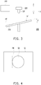
FIG. 3 is a schematic diagram of a 3D printing device according to another embodiment of the invention. -
FIG. 4 is a schematic diagram of first layer slicing data according to an embodiment of the invention. -
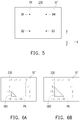
FIG. 5 is a schematic diagram of sensing a plurality of sensing points on a printing platform according to an embodiment of the invention. -
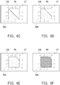
FIGs. 6A-6F are schematic diagrams of multiple layers of sub-objects of a compensation object according to an embodiment of the invention. -
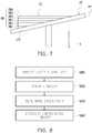
FIG. 7 is a schematic diagram of a compensation object according to an embodiment of the invention. -
FIG. 8 is a flowchart illustrating a 3D printing method according to an embodiment of the invention. - Reference will now be made in detail to the present preferred embodiments of the invention, examples of which are illustrated in the accompanying drawings. Wherever possible, the same reference numbers are used in the drawings and the description to refer to the same or like parts.
-
FIG. 1 is a block schematic diagram of a 3D printing device according to an embodiment of the invention. Referring toFIG. 1 , the3D printing device 100 includes acontroller 110, aprinting head 120, asensor 121 and aprinting platform 130. In the present embodiment, thecontroller 110 is coupled to theprinting head 120 and thesensor 121, and theprinting head 120 and thesensor 121 are disposed above theprinting platform 130. In the present embodiment, thesensor 121 may be disposed in theprinting head 120. Therefore, when thesensor 121 and theprinting head 120 move under control, thesensor 121 and theprinting head 120 move together, such that control of theprinting head 120 and thesensor 121 is simplified, and thesensor 121 may equivalently reflect a status of theprinting head 120. However, in another embodiment, thesensor 121 and theprinting head 120 may also be juxtaposed in mechanism. Alternatively, thesensor 121 may be independently disposed above theprinting platform 130, and is coupled to thecontroller 110, though thesensor 121 is separated from theprinting head 120, and independently moves under control. - In the present embodiment, the
controller 110 controls theprinting head 120 to execute a printing operation, and controls thesensor 121 to sense a plurality of sensing points on theprinting platform 130, so as to obtain a plurality of sensing parameters. In the present embodiment, thesensor 121 is, for example, an infrared sensor or an ultrasonic sensor, etc., though the invention is not limited thereto. When thesensor 121 is respectively moved to positions vertically above the sensing points, thesensor 121 may individually sense a distance between thesensor 121 and the sensing points on theprinting platform 130, or sense a plurality of height values or height differences of the sensing points relative to a horizontal plane, such that thecontroller 110 may determine an inclination degree of theprinting platform 130 according to the sensing parameters. - In the present embodiment, the
controller 110 may include a processing chip, which is, for example, a central processing unit (CPU), or other programmable general purpose or special purpose microprocessor, a digital signal processor (DSP), a programmable controller, an application specific integrated circuits (ASIC), a programmable logic device (PLD), other similar processing circuit or a combination of the above devices. Moreover, in the present embodiment, thecontroller 110 may further include or externally connect a storage device. The storage device is, for example, a dynamic random access memory (DRAM), a flash memory or a non-volatile random access memory (NVRAM), etc. In the present embodiment, the storage device may be used for storing data and parameters of the embodiments of the invention, and may further store a plurality of calculating, processing or analyzing modules for being read and executed by thecontroller 110, such that thecontroller 110 may implement calculating, processing or analyzing operations of the embodiments of the invention. -
FIG. 2 is a schematic diagram of the 3D printing device according to an embodiment of the invention. Referring toFIG. 2 , in the present embodiment, the coordinate axes X, Y, Z are perpendicular to each other. The coordinate axes X and Y are, for example, axial directions of horizontal directions, and the coordinate axis Z is, for example, an axial direction of a vertical direction. The3D printing device 100 of the present embodiment may be placed in a space formed by the coordinate axes X, Y, Z. In the present embodiment, theprinting platform 130 includes a carrying surface S1. Thecontroller 110 may operate theprinting head 120 to move along the horizontal direction or the vertical direction. Thecontroller 110 may operate theprinting head 120 to execute a 3D printing operation on the carrying surface S1 of theprinting platform 130, and control thesensor 121 to sense a plurality of sensing points on the carrying surface S1 of theprinting platform 130, so as to obtain a plurality of sensing parameters. - In the present embodiment, the 3D printing operation refers to that the
controller 110 controls a moving path of theprinting head 120 according to a plurality of slicing information of 3D model information, and operates theprinting head 120 to print at least one sliced object on the carrying surface S1 of theprinting platform 130. In the present embodiment, the3D printing device 100 may sequentially print multiple layers of sliced objects to stack the sliced objects on the carrying surface S1 of theprinting platform 130 to form a 3D objects. In the present embodiment, the 3D model information may be a 3D image file, which may be constructed by a computer host by using computer-aided design (CAD) or animation modeling software. In the present embodiment, the 3D model in the 3D image file may be sliced into a plurality of slicing data by the computer host, and the3D printing device 100 may sequentially print the sliced objects according to the slicing data, where the slicing data is, for example, a two-dimensional (2D) image file. -
FIG. 3 is a schematic diagram of a 3D printing device according to another embodiment of the invention. Referring toFIG. 3 , thecontroller 210 of the3D printing device 200 may operate theprinting head 220 to move along a horizontal direction or a vertical direction, and the3D printing device 200 has been adjusted after being manufactured, where a moving plane of theprinting head 220 along the horizontal direction is substantially parallel to a horizontal plane HP. Thecontroller 210 may operate theprinting head 220 to execute the 3D printing operation on the carrying surface S1' of theprinting platform 230, and may control thesensor 221 to sense a plurality of sensing points on the carrying surface S1' of theprinting platform 230, so as to obtain a plurality of sensing parameters. However, in the present embodiment, if the carrying surface S1' of theprinting platform 230 has a tilt angle θ relative to the horizontal plane HP, the 3D object directly printed on the carrying surface S1' by the3D printing device 200 is skewed or has an error, which influences the printing quality. Therefore, in the present embodiment, thecontroller 210 operates theprinting head 220 to pre-print a compensation object on the carrying surface S1' of theprinting platform 230 before printing the 3D object, and the compensation object forms a horizontal plane on the carrying surface S1'. Moreover, thecontroller 210 operates theprinting head 220 to continually print the 3D object on the horizontal plane formed by the compensation object. -
FIG. 4 is a schematic diagram of first layer slicing data according to an embodiment of the invention. Referring toFIG. 3 and FIG. 4 , inFIG. 3 , the first layer slicing data SI may be a 2D image file, and the image file includes a first layer sliced object SB of the 3D object. In the present embodiment, before the compensation object is printed, thecontroller 210 analyzes the first layer slicing data SI of the 3D object to obtain a printing range PR. Namely, the3D printing device 200 determines the printing range PR of the compensation object according to a contour range of the first layer sliced object SB of the 3D object. In the present embodiment, the printing range PR forms a rectangle region on the carrying surface S1', and after printing of the compensation object is completed, a range of the sliced object SB printed by the printing head according to the first layer slicing data SI under control of thecontroller 210 does not exceed the printing range PR. However, the printing range PR of the invention is not limited toFIG. 4 . In an embodiment, a size and a shape of the printing range PR may be determined according to a shape of the 3D object, or predetermined by the user. -
FIG. 5 is a schematic diagram of sensing a plurality of sensing points on a printing platform according to an embodiment of the invention. Referring toFIG. 3 andFIG. 5 , in the present embodiment, after the3D printing device 200 determines the printing range PR, thecontroller 210 operates theprinting head 220 and thesensor 221 to sense a plurality of sensing points D1-D4 corresponding to the printing range PR on the carrying surface S1' of theprinting platform 230, so as to obtain a plurality of sensing parameters corresponding to the sensing points D1-D4. However, the quantity and the sensing positions of the sensing points are not limited to that shown inFIG. 5 . In an embodiment, the quantity and the sensing positions of the sensing points may be determined according to the printing range, or preset by the user. - In the present embodiment, the sensing parameters sensed by the
sensor 221 are a plurality of height values. Thecontroller 210 may respectively calculate the height values based on a slope formula and a predetermined pitch to obtain a plurality of height differences, and thecontroller 210 may determine a plurality of sub-object shapes and a plurality of sub-object heights of the multiplayer of sub-objects of the compensation object according to the slope formula, the predetermined pitch and the height differences. To be specific, the3D printing device 200 may take a position of the highest point of the printing range PR as a reference, and calculate height differences between other positions and the reference along the printing range PR according to the predetermined pitch. Therefore, the3D printing device 200 may determine a quantity of the sub-objects of the compensation object according to a distribution status of the height differences, and further design the sub-object shapes and the sub-object heights. -
FIGs. 6A-6F are schematic diagrams of the multiple layers of sub-objects of the compensation object according to an embodiment of the invention. Referring toFIGs. 6A-6F , in the present embodiment, the3D printing device 200 may sequentially print multiplayer of sub-objects OB1-OB6 on the carrying surface S1' of theprinting platform 230, and the sub-objects OB1-OB6 are sequentially stacked to form the compensation object. InFIGs. 6A-6F , thecontroller 210 may set the predetermined pitch as one unit pitch of 1 cm, 2 cm, or 5 cm, though the invention is not limited thereto. Therefore, inFIGs. 6A-6F , thecontroller 210 may mark a plurality of height differences (for example, digits such as 0, -1, -2, ..., -6 marked on each grid point of the printing range PR ofFIG. 6A ) along the printing range PR based on the predetermined pitch (for example, a space between two adjacent grid points on the printing range PR ofFIG. 6A ), so as to operate theprinting head 220 to sequentially print the sub-objects OB1-OB6 according to a variation trend of the height differences. - To be specific, in
FIG. 6A , thecontroller 210 may determine a region with a relative lowest height in the printing range PR on the carrying surface S1' of theprinting platform 230, where such region is, for example, a region formed by the height differences marked as "-5", "-5" and "-6". In the present embodiment, thecontroller 210 may operate theprinting head 220 to print the sub-object OB1 on such region. - In
FIG. 6B , since the sub-object OBI has been printed in the printing range PR on the carrying surface S1' of theprinting platform 230, the sub-object OBI has compensated a height of partial region in the printing range PR. Namely, thecontroller 210 then determines a region with the relative lowest height in the printing range PR on the carrying surface S1' of theprinting platform 230, where such region is, for example, a region formed by the height differences marked as "-4" and "-5". In the present embodiment, thecontroller 210 may operate theprinting head 220 to print the sub-object OB2 on such region. - In
FIG. 6C , since the sub-objects OB1, OB2 have been printed in the printing range PR on the carrying surface S1' of theprinting platform 230, the sub-objects OBI, OB2 have compensated a height of partial region in the printing range PR. Namely, thecontroller 210 then determines a region with the relative lowest height in the printing range PR on the carrying surface S1' of theprinting platform 230, where such region is, for example, a region formed by the height differences marked as "-3" and "-4". In the present embodiment, thecontroller 210 may operate theprinting head 220 to print the sub-object OB3 on such region. - In
FIG. 6D , since the sub-objects OBI, OB2, OB3 have been printed in the printing range PR on the carrying surface S1' of theprinting platform 230, the sub-objects OB1, OB2, OB3 have compensated a height of partial region in the printing range PR. Namely, thecontroller 210 then determines a region with the relative lowest height in the printing range PR on the carrying surface S1' of theprinting platform 230, where such region is, for example, a region formed by the height differences marked as "-2" and "-3". In the present embodiment, thecontroller 210 may operate theprinting head 220 to print the sub-object OB4 on such region. - In
FIG. 6E , since the sub-objects OB1, OB2, OB3, OB4 have been printed in the printing range PR on the carrying surface S1' of theprinting platform 230, the sub-objects OB1, OB2, OB3, OB4 have compensated a height of partial region in the printing range PR. Namely, thecontroller 210 then determines a region with the relative lowest height in the printing range PR on the carrying surface S1' of theprinting platform 230, where such region is, for example, a region formed by the height differences marked as "-1" and "-2". In the present embodiment, thecontroller 210 may operate theprinting head 220 to print the sub-object OB5 on such region. - In
FIG. 6F , since the sub-objects OB1, OB2, OB3, OB4, OB5 have been printed in the printing range PR on the carrying surface S1' of theprinting platform 230, the sub-objects OB1, OB2, OB3, OB4, OB5 have compensated a height of partial region in the printing range PR. Namely, thecontroller 210 then determines a region with the relative lowest height in the printing range PR on the carrying surface S1' of theprinting platform 230, where such region is, for example, a region formed by the height differences marked as "-0" and "-1". In the present embodiment, thecontroller 210 may operate theprinting head 220 to print the sub-object OB6 on such region. In the present embodiment, the sub-object OB6 is the last layer sub-object of the compensation object, and the sub-object OB6 may be a partially filled structure as that shown inFIG. 6F . To be specific, since the3D printing device 200 may continually print the 3D object on the compensation object, in order to easily separate the 3D object from the compensation object after the 3D printing operation, the sub-object OB6 be designed into a partially filled structure. However, the partially filled structure of the sub-object OB6 is not limited to a structure type shown inFIG. 6F . In an embodiment, the partially filled structure of the sub-object OB6 may be designed according to a shape, a size of the 3D object or designed by the user. - In the embodiment of
FIGs. 6A-6F , the heights of the sub-objects OB1-OB6 printed by the3D printing device 200 are the same. Thecontroller 210 may determine shapes and heights of the sub-objects OB1-OB6 according to the slope formula, the predetermined pitch and the height differences. Moreover, the height differences may be calculated according to a trigonometric function formula of the related technical field, and enough instructions and recommendations thereof may be obtained from the ordinary knowledge of the related technical field, detailed description thereof is not repeated. However, in an embodiment, the sub-objects OB1-OB6 may have different heights, which is not limited by the invention. -
FIG. 7 is a schematic diagram of a compensation object according to an embodiment of the invention. Referring toFIG. 3 andFIG. 7 , in the present embodiment, the compensation object OB may be formed by sequentially stacking a plurality of the sub-objects OB1-OB6, and an area of each layer of sub-object of the sub-objects OB1-OB6 is increased layer-by-layer from the first layer sub-object OB1 to the last layer sub-object OB6. In the present embodiment, the compensation object OB forms another carrying surface S2 on the carrying surface S1' of theprinting platform 230, and the carrying surface S2 is parallel to the horizontal plane HP. Namely, since the carrying surface S1' of theprinting platform 230 is not the horizontal plane, the3D printing device 200 of the present embodiment may pre-print the compensation object on the carrying surface S1' of theprinting platform 230 before printing the 3D object, such that the compensation object forms the other carrying surface S2 on the carrying surface S1', and the carrying surface S2 is a horizontal plane. Therefore, when thecontroller 210 operates theprinting head 220 to continually print the 3D object on the carrying surface S2 formed by the compensation object, the 3D object may be correctly printed on the horizontal plane. -
FIG. 8 is a flowchart illustrating a 3D printing method according to an embodiment of the invention. Referring toFIG. 1 andFIG. 8 , the 3D printing method of the present embodiment is at least adapted to the3D printing device 100 ofFIG. 1 . In step S810, thecontroller 110 analyzes a first layer slicing data of the 3D object to obtain a printing range. In step S820, thecontroller 110 operates thesensor 121 to sense a plurality of sensing points corresponding to the printing range on the carrying surface of theprinting platform 130, so as to obtain a plurality of sensing parameters corresponding to the sensing points. In step S830, thecontroller 110 determines whether theprinting platform 130 is inclined according to the sensing parameters. In step S840, If theprinting platform 130 is inclined, thecontroller 110 determines an object shape of the compensation object according to the printing range and the sensing parameters. Although the so-called "object shape" of the compensation object is probably deconstructed to include an appearance sensory feeling such as a geometric shape or a height or an angle, etc., or measured parameters, for example, in the aforementioned embodiment, the compensation object may be formed by stacking multiple layers of sub-objects, and the multiple layers of sub-objects respectively include the sub-object shapes and sub-object heights. However, the term "object shape" of the compensation object is not particularly used for emphasizing the same, but is to compensate the inclination of the printing platform by using the compensation object, such that the 3D object may be correctly printed on the horizontal plane. Therefore, the 3D printing method of the present embodiment may automatically correct the inclination of the printing platform, so as to correctly print the 3D object on the horizontal plane. - Moreover, enough instructions and recommendations of related implementation details and related device features of the
3D printing device 100 of the present embodiment may be acquired from the embodiments ofFIG. 1 to FIG. 7 , and detail thereof is not repeated. - In summary, the 3D printing device and the 3D printing method of the invention are adapted to automatically determine whether the printing platform is inclined, and when the printing platform is inclined, the 3D printing device pre-prints at least one layer sub-object to form the compensation object, such that the 3D object is printed on the horizontal plane formed by the compensation object. Moreover, the last layer sub-object of the sub-objects may be designed as a partially filled structure, so as to facilitate separating the 3D object from the compensation object. Therefore, the 3D printing device and the 3D printing method of the invention automatically compensate and correct the inclination of the printing platform to achieve good printing quality.
Claims (12)
- A three-dimensional printing device (100, 200), comprising:a printing platform (130, 230), comprising a carrying surface (S1, S1');a printing head (120, 220), disposed above the printing platform (130, 230);a sensor (121, 221), disposed above the printing platform (130, 230); anda controller (110, 210), coupled to the printing head (120, 220) and the sensor (121, 221),wherein the controller (110, 210) is configured to:analyze a first layer slicing data (SI) of a three-dimensional object to obtain a printing range (PR), and operate the sensor (121, 221) to sense a plurality of sensing points (D1, D2, D3, D4) corresponding to the printing range (PR) on the carrying surface (S1, S1') of the printing platform (130, 230), so as to obtain a plurality of sensing parameters corresponding to the sensing points (D1, D2, D3, D4),determine whether the printing platform (130, 230) is inclined according to the sensing parameters,if the printing platform 15 (130, 230) is inclined, determine an object shape of a compensation object (OB) according to the printing range (PR) and the sensing parameters, andoperate the printing head (120, 220) to pre-print the compensation object (OB) on the carrying surface (S1, S1') of the printing platform (130, 230) before printing the three-dimensional object.
- The three-dimensional printing device (100, 200) as claimed in claim 1, wherein the compensation object (OB) forms a horizontal plane (HB) on the carrying surface (S1, S1'), and the printing head (120, 220) is configured to print the three-dimensional object on the horizontal plane (HB).
- The three-dimensional printing device (100, 200) as claimed in claim 1, wherein the compensation object (OB) is formed by sequentially stacking multiple layers of sub-objects (OB1, OB2, OB3, OB4, OB5, OB6), and the controller (110, 210) is configured to respectively calculate a plurality of sub-object shapes and a plurality of sub-object heights of the multiple layers of sub-objects (OB1, OB2, OB3, OB4, OB5, OB6) according to the printing range (PR) and the sensing parameters.
- The three-dimensional printing device (100, 200) as claimed in claim 3, wherein the sensing parameters are a plurality of height values, and the controller (110, 210) is configured to calculate the height values according to a slope formula and a predetermined pitch to obtain a plurality of height differences, and to determine the sub-object shapes and the sub-object heights of the multiple layers of sub-objects (OB1, OB2, OB3, OB4, OB5, OB6) according to the slope formula, the predetermined pitch and the height differences.
- The three-dimensional printing device (100, 200) as claimed in claim 3, wherein an area of each layer of sub-object of the multiple layers of sub-objects (OB1, OB2, OB3, OB4, OB5, OB6) is increased layer-by-layer from a first layer sub-object to a last layer sub-object, or the last layer sub-object of the multiple layers of sub-objects (OB1, OB2, OB3, OB4, OB5, OB6) is a partially filled structure.
- The three-dimensional printing device (100, 200) as claimed in claim 1, wherein the printing range (PR) forms a rectangle region on the carrying surface (S1, S1'), and a range of a sliced object (SB) printed by the printing head (120, 220) according to the first layer slicing data (SI) under control of the controller (110, 210) does not exceed the printing range (PR).
- A three-dimensional printing method, adapted to a three-dimensional printing device (100, 200), and comprising:analyzing a first layer slicing data (SI) of a three-dimensional object to obtain a printing range (PR);operating a sensor (121, 221) to sense a plurality of sensing points (D1, D2, D3, D4) corresponding to the printing range (PR) on a carrying surface (S1, S1') of a printing platform (130, 230), so as to obtain a plurality of sensing parameters corresponding to the sensing points (D1, D2, D3, D4);determining whether the printing platform (130, 230) is inclined according to the sensing parameters;if the printing platform (130, 230) is inclined, determining an object shape of a compensation object (OB) according to the printing range (PR) and the sensing parameters, andoperating the printing head (120, 220) to pre-print the compensation object (OB) on the carrying surface (S1, S1') of the printing platform (130, 230) before printing the three-dimensional object.
- The three-dimensional printing method as claimed in claim 7, wherein the compensation object (OB) forms a horizontal plane (HB) on the carrying surface (S1, S1'), and the three-dimensional printing method further comprises:
operating the printing head (120, 220) to print the three-dimensional object on the horizontal plane (HB). - The three-dimensional printing method as claimed in claim 7, wherein the compensation object (OB) is formed by sequentially stacking multiple layers of sub-objects (OB1, OB2, OB3, OB4, OB5, OB6), and the step of determining the object shape of the compensation object (OB) according to the printing range (PR) and the sensing parameters comprises:
respectively calculating a plurality of sub-object shapes and a plurality of sub-object heights of the multiple layers of sub-objects (OB1, OB2, OB3, OB4, OB5, OB6) according to the printing range (PR) and the sensing parameters. - The three-dimensional printing method as claimed in claim 9, wherein the sensing parameters are a plurality of height values, and the step of calculating the sub-object shapes and the sub-object heights of the multiple layers of sub-objects (OB1, OB2, OB3, OB4, OB5, OB6) comprises:calculating the height values according to a slope formula and a predetermined pitch to obtain a plurality of height differences; anddetermining the sub-object shapes and the sub-object heights of the multiple layers of sub-objects (OB1, OB2, OB3, OB4, OB5, OB6) according to the slope formula, the predetermined pitch and the height differences.
- The three-dimensional printing method as claimed in claim 9, wherein an area of each layer of sub-object of the multiple layers of sub-objects (OB1, OB2, OB3, OB4, OB5, OB6) is increased layer-by-layer from a first layer sub-object to a last layer sub-object, or the last layer sub-object of the multiple layers of sub-objects (OB1, OB2, OB3, OB4, OB5, OB6) is a partially filled structure.
- The three-dimensional printing method as claimed in claim 7, wherein the printing range (PR) forms a rectangle region on the carrying surface (S1, S1'), and a range of a sliced object (SB) printed by the printing head (120, 220) according to the first layer slicing data (SI) does not exceed the printing range (PR).
Applications Claiming Priority (1)
| Application Number | Priority Date | Filing Date | Title |
|---|---|---|---|
| CN201710605216.4A CN109291433A (en) | 2017-07-24 | 2017-07-24 | Three-dimensional printing apparatus and three-dimensional printing method |
Publications (2)
| Publication Number | Publication Date |
|---|---|
| EP3434451A1 EP3434451A1 (en) | 2019-01-30 |
| EP3434451B1 true EP3434451B1 (en) | 2020-04-01 |
Family
ID=62567359
Family Applications (1)
| Application Number | Title | Priority Date | Filing Date |
|---|---|---|---|
| EP18176068.7A Active EP3434451B1 (en) | 2017-07-24 | 2018-06-05 | Three-dimensional printing device and three-dimensional printing method |
Country Status (5)
| Country | Link |
|---|---|
| US (1) | US20190022947A1 (en) |
| EP (1) | EP3434451B1 (en) |
| JP (1) | JP6678200B2 (en) |
| CN (1) | CN109291433A (en) |
| ES (1) | ES2790375T3 (en) |
Families Citing this family (14)
| Publication number | Priority date | Publication date | Assignee | Title |
|---|---|---|---|---|
| US12251879B2 (en) * | 2018-12-10 | 2025-03-18 | Bmf Nano Material Technology Co., Ltd. | Methods of controlling dimensions in projection micro stereolithography |
| CN111791477B (en) * | 2019-04-09 | 2023-04-28 | 上海普利生机电科技有限公司 | Three-dimensional printing method and device |
| EP3954530A4 (en) * | 2019-04-09 | 2022-10-26 | Nikon Corporation | MOLDING UNIT |
| CN113246459A (en) * | 2020-02-13 | 2021-08-13 | 三纬国际立体列印科技股份有限公司 | Three-dimensional printing device and method |
| CN111483138B (en) * | 2020-04-16 | 2021-10-29 | 杭州喜马拉雅信息科技有限公司 | Printing platform for reducing 3D printing support |
| CN112036041B (en) * | 2020-09-02 | 2024-04-19 | 河北工业大学 | Comprehensive compensation method for STL model permeation error in 3DP process |
| US12420486B2 (en) | 2020-10-23 | 2025-09-23 | Bmf Material Technology Inc. | Multi-scale system for projection micro stereolithography |
| CN112348946B (en) * | 2020-11-04 | 2024-08-20 | 深圳市纵维立方科技有限公司 | Printing processing method, device, electronic device and storage medium |
| CN115723333B (en) * | 2021-08-30 | 2024-04-09 | 广州黑格智造信息科技有限公司 | A 3D printing method, system, device and storage medium |
| EP4384379A1 (en) | 2021-08-13 | 2024-06-19 | Bmf Nano Material Technology Co., Ltd | System and method of low-waste multi-material resin printing |
| CN114055780B (en) * | 2021-10-26 | 2023-05-30 | 深圳市纵维立方科技有限公司 | 3D printer automatic leveling method, storage medium and 3D printing equipment |
| CN117341204B (en) * | 2022-06-29 | 2025-10-24 | 深圳市创想三维科技股份有限公司 | Printing platform height compensation method, device and computer equipment |
| EP4662050A1 (en) * | 2023-02-10 | 2025-12-17 | 3D Systems, Inc. | Method for manufacturing low modulus articles |
| CN116749521A (en) * | 2023-05-10 | 2023-09-15 | 深圳市纵维立方科技有限公司 | Leveling method, device, storage medium and three-dimensional printer of three-dimensional printer |
Family Cites Families (7)
| Publication number | Priority date | Publication date | Assignee | Title |
|---|---|---|---|---|
| JP2015157420A (en) * | 2014-02-25 | 2015-09-03 | 日本電子株式会社 | Three-dimensional laminate molding apparatus |
| US10252466B2 (en) * | 2014-07-28 | 2019-04-09 | Massachusetts Institute Of Technology | Systems and methods of machine vision assisted additive fabrication |
| CN106273453B (en) * | 2015-06-05 | 2018-09-25 | 三纬国际立体列印科技股份有限公司 | Three-dimensional printing device and printing error correction method thereof |
| CN204894524U (en) * | 2015-07-02 | 2015-12-23 | 深圳长朗三维科技有限公司 | 3d printer |
| TWI568571B (en) * | 2015-08-28 | 2017-02-01 | 東友科技股份有限公司 | Print platform adjustment system and adjustment method therefor |
| CN106799837B (en) * | 2015-11-20 | 2019-02-12 | 三纬国际立体列印科技股份有限公司 | Three-axis parallel type 3D printer and correction method thereof |
| JP2018024176A (en) * | 2016-08-10 | 2018-02-15 | キヤノン株式会社 | Modeling apparatus and modeling method |
-
2017
- 2017-07-24 CN CN201710605216.4A patent/CN109291433A/en active Pending
-
2018
- 2018-03-30 US US15/942,428 patent/US20190022947A1/en not_active Abandoned
- 2018-05-25 JP JP2018100168A patent/JP6678200B2/en not_active Expired - Fee Related
- 2018-06-05 EP EP18176068.7A patent/EP3434451B1/en active Active
- 2018-06-05 ES ES18176068T patent/ES2790375T3/en active Active
Non-Patent Citations (1)
| Title |
|---|
| None * |
Also Published As
| Publication number | Publication date |
|---|---|
| JP6678200B2 (en) | 2020-04-08 |
| EP3434451A1 (en) | 2019-01-30 |
| JP2019022982A (en) | 2019-02-14 |
| ES2790375T3 (en) | 2020-10-27 |
| CN109291433A (en) | 2019-02-01 |
| US20190022947A1 (en) | 2019-01-24 |
Similar Documents
| Publication | Publication Date | Title |
|---|---|---|
| EP3434451A1 (en) | Three-dimensional printing device and three-dimensional printing method | |
| US11797927B2 (en) | Tray space planning method, palletizing method and apparatus thereof, and electronic device | |
| JP6036662B2 (en) | Robot simulation apparatus, program, recording medium and method | |
| WO2022143796A1 (en) | Calibration method and calibration device for line structured light measurement system, and system | |
| US9827718B2 (en) | Three-dimensional printing device | |
| CN108274754B (en) | Three-dimensional printing device and printing correction method | |
| US20190011902A1 (en) | Three-dimensional printing apparatus and three-dimensional printing method | |
| CN102105908A (en) | Method and device for the production of a master pattern tool | |
| US20150057781A1 (en) | Three dimensional printer and method for adjusting working coordinate of platform thereof | |
| TW200848963A (en) | Program producing device, numerical value control device and program producing method | |
| WO2020217878A1 (en) | Device, method, and program for detecting position and orientation of object | |
| TWI668124B (en) | Three dimension printing coloring method and three-dimension printing system | |
| US20170151716A1 (en) | Three dimensional printing method and apparatus using the same | |
| JP2021017047A (en) | Horizontal plane slicing method for color 3d objects | |
| US11941852B2 (en) | Three-dimensional measurement device, three-dimensional measurement method, and three-dimensional measurement program | |
| JP6692844B2 (en) | Inkjet method and 3D printing apparatus | |
| CN119887929A (en) | Calibration method and three-dimensional reconstruction method based on line laser scanning | |
| US20190176371A1 (en) | Three-dimensional printing device and three-dimensional printing method | |
| CN110675384B (en) | Image processing method and device | |
| TWI704995B (en) | Slicing method for horizontal facets of color 3d object | |
| TWI695773B (en) | Inkjet method and three-dimensional printing device | |
| US12282999B2 (en) | 3D printing slicing method, apparatus, device, and storage medium | |
| JP7649184B2 (en) | Information processing device, information processing method, and program | |
| CN118650883A (en) | 3D model placement method and system, computer equipment and storage medium | |
| CN118721749A (en) | 3D model placement method and system, computer equipment and storage medium |
Legal Events
| Date | Code | Title | Description |
|---|---|---|---|
| PUAI | Public reference made under article 153(3) epc to a published international application that has entered the european phase |
Free format text: ORIGINAL CODE: 0009012 |
|
| STAA | Information on the status of an ep patent application or granted ep patent |
Free format text: STATUS: THE APPLICATION HAS BEEN PUBLISHED |
|
| AK | Designated contracting states |
Kind code of ref document: A1 Designated state(s): AL AT BE BG CH CY CZ DE DK EE ES FI FR GB GR HR HU IE IS IT LI LT LU LV MC MK MT NL NO PL PT RO RS SE SI SK SM TR |
|
| AX | Request for extension of the european patent |
Extension state: BA ME |
|
| STAA | Information on the status of an ep patent application or granted ep patent |
Free format text: STATUS: REQUEST FOR EXAMINATION WAS MADE |
|
| 17P | Request for examination filed |
Effective date: 20190729 |
|
| RBV | Designated contracting states (corrected) |
Designated state(s): AL AT BE BG CH CY CZ DE DK EE ES FI FR GB GR HR HU IE IS IT LI LT LU LV MC MK MT NL NO PL PT RO RS SE SI SK SM TR |
|
| GRAP | Despatch of communication of intention to grant a patent |
Free format text: ORIGINAL CODE: EPIDOSNIGR1 |
|
| STAA | Information on the status of an ep patent application or granted ep patent |
Free format text: STATUS: GRANT OF PATENT IS INTENDED |
|
| RIC1 | Information provided on ipc code assigned before grant |
Ipc: B29C 64/106 20170101ALI20191120BHEP Ipc: B29C 64/40 20170101ALI20191120BHEP Ipc: B29C 64/393 20170101AFI20191120BHEP |
|
| INTG | Intention to grant announced |
Effective date: 20191212 |
|
| RIN1 | Information on inventor provided before grant (corrected) |
Inventor name: YANG, YU-JIE Inventor name: HO, KWAN |
|
| GRAS | Grant fee paid |
Free format text: ORIGINAL CODE: EPIDOSNIGR3 |
|
| GRAA | (expected) grant |
Free format text: ORIGINAL CODE: 0009210 |
|
| STAA | Information on the status of an ep patent application or granted ep patent |
Free format text: STATUS: THE PATENT HAS BEEN GRANTED |
|
| AK | Designated contracting states |
Kind code of ref document: B1 Designated state(s): AL AT BE BG CH CY CZ DE DK EE ES FI FR GB GR HR HU IE IS IT LI LT LU LV MC MK MT NL NO PL PT RO RS SE SI SK SM TR |
|
| REG | Reference to a national code |
Ref country code: GB Ref legal event code: FG4D |
|
| REG | Reference to a national code |
Ref country code: CH Ref legal event code: EP Ref country code: AT Ref legal event code: REF Ref document number: 1250821 Country of ref document: AT Kind code of ref document: T Effective date: 20200415 |
|
| REG | Reference to a national code |
Ref country code: DE Ref legal event code: R096 Ref document number: 602018003380 Country of ref document: DE |
|
| REG | Reference to a national code |
Ref country code: IE Ref legal event code: FG4D |
|
| PGFP | Annual fee paid to national office [announced via postgrant information from national office to epo] |
Ref country code: FR Payment date: 20200611 Year of fee payment: 3 |
|
| PG25 | Lapsed in a contracting state [announced via postgrant information from national office to epo] |
Ref country code: BG Free format text: LAPSE BECAUSE OF FAILURE TO SUBMIT A TRANSLATION OF THE DESCRIPTION OR TO PAY THE FEE WITHIN THE PRESCRIBED TIME-LIMIT Effective date: 20200701 |
|
| REG | Reference to a national code |
Ref country code: NL Ref legal event code: MP Effective date: 20200401 |
|
| REG | Reference to a national code |
Ref country code: LT Ref legal event code: MG4D |
|
| REG | Reference to a national code |
Ref country code: ES Ref legal event code: FG2A Ref document number: 2790375 Country of ref document: ES Kind code of ref document: T3 Effective date: 20201027 |
|
| PG25 | Lapsed in a contracting state [announced via postgrant information from national office to epo] |
Ref country code: CZ Free format text: LAPSE BECAUSE OF FAILURE TO SUBMIT A TRANSLATION OF THE DESCRIPTION OR TO PAY THE FEE WITHIN THE PRESCRIBED TIME-LIMIT Effective date: 20200401 Ref country code: IS Free format text: LAPSE BECAUSE OF FAILURE TO SUBMIT A TRANSLATION OF THE DESCRIPTION OR TO PAY THE FEE WITHIN THE PRESCRIBED TIME-LIMIT Effective date: 20200801 Ref country code: GR Free format text: LAPSE BECAUSE OF FAILURE TO SUBMIT A TRANSLATION OF THE DESCRIPTION OR TO PAY THE FEE WITHIN THE PRESCRIBED TIME-LIMIT Effective date: 20200702 Ref country code: LT Free format text: LAPSE BECAUSE OF FAILURE TO SUBMIT A TRANSLATION OF THE DESCRIPTION OR TO PAY THE FEE WITHIN THE PRESCRIBED TIME-LIMIT Effective date: 20200401 Ref country code: PT Free format text: LAPSE BECAUSE OF FAILURE TO SUBMIT A TRANSLATION OF THE DESCRIPTION OR TO PAY THE FEE WITHIN THE PRESCRIBED TIME-LIMIT Effective date: 20200817 Ref country code: NL Free format text: LAPSE BECAUSE OF FAILURE TO SUBMIT A TRANSLATION OF THE DESCRIPTION OR TO PAY THE FEE WITHIN THE PRESCRIBED TIME-LIMIT Effective date: 20200401 Ref country code: NO Free format text: LAPSE BECAUSE OF FAILURE TO SUBMIT A TRANSLATION OF THE DESCRIPTION OR TO PAY THE FEE WITHIN THE PRESCRIBED TIME-LIMIT Effective date: 20200701 Ref country code: SE Free format text: LAPSE BECAUSE OF FAILURE TO SUBMIT A TRANSLATION OF THE DESCRIPTION OR TO PAY THE FEE WITHIN THE PRESCRIBED TIME-LIMIT Effective date: 20200401 Ref country code: FI Free format text: LAPSE BECAUSE OF FAILURE TO SUBMIT A TRANSLATION OF THE DESCRIPTION OR TO PAY THE FEE WITHIN THE PRESCRIBED TIME-LIMIT Effective date: 20200401 |
|
| PGFP | Annual fee paid to national office [announced via postgrant information from national office to epo] |
Ref country code: ES Payment date: 20200701 Year of fee payment: 3 Ref country code: DE Payment date: 20200630 Year of fee payment: 3 |
|
| REG | Reference to a national code |
Ref country code: AT Ref legal event code: MK05 Ref document number: 1250821 Country of ref document: AT Kind code of ref document: T Effective date: 20200401 |
|
| PG25 | Lapsed in a contracting state [announced via postgrant information from national office to epo] |
Ref country code: RS Free format text: LAPSE BECAUSE OF FAILURE TO SUBMIT A TRANSLATION OF THE DESCRIPTION OR TO PAY THE FEE WITHIN THE PRESCRIBED TIME-LIMIT Effective date: 20200401 Ref country code: HR Free format text: LAPSE BECAUSE OF FAILURE TO SUBMIT A TRANSLATION OF THE DESCRIPTION OR TO PAY THE FEE WITHIN THE PRESCRIBED TIME-LIMIT Effective date: 20200401 Ref country code: LV Free format text: LAPSE BECAUSE OF FAILURE TO SUBMIT A TRANSLATION OF THE DESCRIPTION OR TO PAY THE FEE WITHIN THE PRESCRIBED TIME-LIMIT Effective date: 20200401 |
|
| PG25 | Lapsed in a contracting state [announced via postgrant information from national office to epo] |
Ref country code: AL Free format text: LAPSE BECAUSE OF FAILURE TO SUBMIT A TRANSLATION OF THE DESCRIPTION OR TO PAY THE FEE WITHIN THE PRESCRIBED TIME-LIMIT Effective date: 20200401 |
|
| REG | Reference to a national code |
Ref country code: DE Ref legal event code: R097 Ref document number: 602018003380 Country of ref document: DE |
|
| PG25 | Lapsed in a contracting state [announced via postgrant information from national office to epo] |
Ref country code: EE Free format text: LAPSE BECAUSE OF FAILURE TO SUBMIT A TRANSLATION OF THE DESCRIPTION OR TO PAY THE FEE WITHIN THE PRESCRIBED TIME-LIMIT Effective date: 20200401 Ref country code: MC Free format text: LAPSE BECAUSE OF FAILURE TO SUBMIT A TRANSLATION OF THE DESCRIPTION OR TO PAY THE FEE WITHIN THE PRESCRIBED TIME-LIMIT Effective date: 20200401 Ref country code: RO Free format text: LAPSE BECAUSE OF FAILURE TO SUBMIT A TRANSLATION OF THE DESCRIPTION OR TO PAY THE FEE WITHIN THE PRESCRIBED TIME-LIMIT Effective date: 20200401 Ref country code: AT Free format text: LAPSE BECAUSE OF FAILURE TO SUBMIT A TRANSLATION OF THE DESCRIPTION OR TO PAY THE FEE WITHIN THE PRESCRIBED TIME-LIMIT Effective date: 20200401 Ref country code: DK Free format text: LAPSE BECAUSE OF FAILURE TO SUBMIT A TRANSLATION OF THE DESCRIPTION OR TO PAY THE FEE WITHIN THE PRESCRIBED TIME-LIMIT Effective date: 20200401 Ref country code: SM Free format text: LAPSE BECAUSE OF FAILURE TO SUBMIT A TRANSLATION OF THE DESCRIPTION OR TO PAY THE FEE WITHIN THE PRESCRIBED TIME-LIMIT Effective date: 20200401 |
|
| PLBE | No opposition filed within time limit |
Free format text: ORIGINAL CODE: 0009261 |
|
| STAA | Information on the status of an ep patent application or granted ep patent |
Free format text: STATUS: NO OPPOSITION FILED WITHIN TIME LIMIT |
|
| PG25 | Lapsed in a contracting state [announced via postgrant information from national office to epo] |
Ref country code: PL Free format text: LAPSE BECAUSE OF FAILURE TO SUBMIT A TRANSLATION OF THE DESCRIPTION OR TO PAY THE FEE WITHIN THE PRESCRIBED TIME-LIMIT Effective date: 20200401 Ref country code: SK Free format text: LAPSE BECAUSE OF FAILURE TO SUBMIT A TRANSLATION OF THE DESCRIPTION OR TO PAY THE FEE WITHIN THE PRESCRIBED TIME-LIMIT Effective date: 20200401 |
|
| 26N | No opposition filed |
Effective date: 20210112 |
|
| PG25 | Lapsed in a contracting state [announced via postgrant information from national office to epo] |
Ref country code: LU Free format text: LAPSE BECAUSE OF NON-PAYMENT OF DUE FEES Effective date: 20200605 |
|
| REG | Reference to a national code |
Ref country code: BE Ref legal event code: MM Effective date: 20200630 |
|
| PG25 | Lapsed in a contracting state [announced via postgrant information from national office to epo] |
Ref country code: IE Free format text: LAPSE BECAUSE OF NON-PAYMENT OF DUE FEES Effective date: 20200605 |
|
| PG25 | Lapsed in a contracting state [announced via postgrant information from national office to epo] |
Ref country code: BE Free format text: LAPSE BECAUSE OF NON-PAYMENT OF DUE FEES Effective date: 20200630 Ref country code: SI Free format text: LAPSE BECAUSE OF FAILURE TO SUBMIT A TRANSLATION OF THE DESCRIPTION OR TO PAY THE FEE WITHIN THE PRESCRIBED TIME-LIMIT Effective date: 20200401 |
|
| PGFP | Annual fee paid to national office [announced via postgrant information from national office to epo] |
Ref country code: IT Payment date: 20210630 Year of fee payment: 4 |
|
| REG | Reference to a national code |
Ref country code: DE Ref legal event code: R119 Ref document number: 602018003380 Country of ref document: DE |
|
| REG | Reference to a national code |
Ref country code: CH Ref legal event code: PL |
|
| PG25 | Lapsed in a contracting state [announced via postgrant information from national office to epo] |
Ref country code: LI Free format text: LAPSE BECAUSE OF NON-PAYMENT OF DUE FEES Effective date: 20210630 Ref country code: DE Free format text: LAPSE BECAUSE OF NON-PAYMENT OF DUE FEES Effective date: 20220101 Ref country code: CH Free format text: LAPSE BECAUSE OF NON-PAYMENT OF DUE FEES Effective date: 20210630 |
|
| PG25 | Lapsed in a contracting state [announced via postgrant information from national office to epo] |
Ref country code: TR Free format text: LAPSE BECAUSE OF FAILURE TO SUBMIT A TRANSLATION OF THE DESCRIPTION OR TO PAY THE FEE WITHIN THE PRESCRIBED TIME-LIMIT Effective date: 20200401 Ref country code: MT Free format text: LAPSE BECAUSE OF FAILURE TO SUBMIT A TRANSLATION OF THE DESCRIPTION OR TO PAY THE FEE WITHIN THE PRESCRIBED TIME-LIMIT Effective date: 20200401 Ref country code: FR Free format text: LAPSE BECAUSE OF NON-PAYMENT OF DUE FEES Effective date: 20210630 Ref country code: CY Free format text: LAPSE BECAUSE OF FAILURE TO SUBMIT A TRANSLATION OF THE DESCRIPTION OR TO PAY THE FEE WITHIN THE PRESCRIBED TIME-LIMIT Effective date: 20200401 |
|
| PG25 | Lapsed in a contracting state [announced via postgrant information from national office to epo] |
Ref country code: MK Free format text: LAPSE BECAUSE OF FAILURE TO SUBMIT A TRANSLATION OF THE DESCRIPTION OR TO PAY THE FEE WITHIN THE PRESCRIBED TIME-LIMIT Effective date: 20200401 |
|
| REG | Reference to a national code |
Ref country code: ES Ref legal event code: FD2A Effective date: 20220727 |
|
| PG25 | Lapsed in a contracting state [announced via postgrant information from national office to epo] |
Ref country code: ES Free format text: LAPSE BECAUSE OF NON-PAYMENT OF DUE FEES Effective date: 20210606 |
|
| GBPC | Gb: european patent ceased through non-payment of renewal fee |
Effective date: 20220605 |
|
| PG25 | Lapsed in a contracting state [announced via postgrant information from national office to epo] |
Ref country code: GB Free format text: LAPSE BECAUSE OF NON-PAYMENT OF DUE FEES Effective date: 20220605 |
|
| PG25 | Lapsed in a contracting state [announced via postgrant information from national office to epo] |
Ref country code: IT Free format text: LAPSE BECAUSE OF NON-PAYMENT OF DUE FEES Effective date: 20220605 |