EP3434308A1 - Ureteral stent - Google Patents
Ureteral stent Download PDFInfo
- Publication number
- EP3434308A1 EP3434308A1 EP18181191.0A EP18181191A EP3434308A1 EP 3434308 A1 EP3434308 A1 EP 3434308A1 EP 18181191 A EP18181191 A EP 18181191A EP 3434308 A1 EP3434308 A1 EP 3434308A1
- Authority
- EP
- European Patent Office
- Prior art keywords
- ureteral stent
- distal end
- proximal end
- stent
- middle portion
- Prior art date
- Legal status (The legal status is an assumption and is not a legal conclusion. Google has not performed a legal analysis and makes no representation as to the accuracy of the status listed.)
- Granted
Links
Images






Classifications
-
- A—HUMAN NECESSITIES
- A61—MEDICAL OR VETERINARY SCIENCE; HYGIENE
- A61F—FILTERS IMPLANTABLE INTO BLOOD VESSELS; PROSTHESES; DEVICES PROVIDING PATENCY TO, OR PREVENTING COLLAPSING OF, TUBULAR STRUCTURES OF THE BODY, e.g. STENTS; ORTHOPAEDIC, NURSING OR CONTRACEPTIVE DEVICES; FOMENTATION; TREATMENT OR PROTECTION OF EYES OR EARS; BANDAGES, DRESSINGS OR ABSORBENT PADS; FIRST-AID KITS
- A61F2/00—Filters implantable into blood vessels; Prostheses, i.e. artificial substitutes or replacements for parts of the body; Appliances for connecting them with the body; Devices providing patency to, or preventing collapsing of, tubular structures of the body, e.g. stents
- A61F2/82—Devices providing patency to, or preventing collapsing of, tubular structures of the body, e.g. stents
-
- A—HUMAN NECESSITIES
- A61—MEDICAL OR VETERINARY SCIENCE; HYGIENE
- A61M—DEVICES FOR INTRODUCING MEDIA INTO, OR ONTO, THE BODY; DEVICES FOR TRANSDUCING BODY MEDIA OR FOR TAKING MEDIA FROM THE BODY; DEVICES FOR PRODUCING OR ENDING SLEEP OR STUPOR
- A61M27/00—Drainage appliance for wounds or the like, i.e. wound drains, implanted drains
- A61M27/002—Implant devices for drainage of body fluids from one part of the body to another
- A61M27/008—Implant devices for drainage of body fluids from one part of the body to another pre-shaped, for use in the urethral or ureteral tract
-
- A—HUMAN NECESSITIES
- A61—MEDICAL OR VETERINARY SCIENCE; HYGIENE
- A61M—DEVICES FOR INTRODUCING MEDIA INTO, OR ONTO, THE BODY; DEVICES FOR TRANSDUCING BODY MEDIA OR FOR TAKING MEDIA FROM THE BODY; DEVICES FOR PRODUCING OR ENDING SLEEP OR STUPOR
- A61M25/00—Catheters; Hollow probes
- A61M25/0021—Catheters; Hollow probes characterised by the form of the tubing
-
- A—HUMAN NECESSITIES
- A61—MEDICAL OR VETERINARY SCIENCE; HYGIENE
- A61M—DEVICES FOR INTRODUCING MEDIA INTO, OR ONTO, THE BODY; DEVICES FOR TRANSDUCING BODY MEDIA OR FOR TAKING MEDIA FROM THE BODY; DEVICES FOR PRODUCING OR ENDING SLEEP OR STUPOR
- A61M25/00—Catheters; Hollow probes
- A61M25/0021—Catheters; Hollow probes characterised by the form of the tubing
- A61M25/0023—Catheters; Hollow probes characterised by the form of the tubing by the form of the lumen, e.g. cross-section, variable diameter
- A61M25/0026—Multi-lumen catheters with stationary elements
- A61M25/003—Multi-lumen catheters with stationary elements characterized by features relating to least one lumen located at the distal part of the catheter, e.g. filters, plugs or valves
-
- A—HUMAN NECESSITIES
- A61—MEDICAL OR VETERINARY SCIENCE; HYGIENE
- A61M—DEVICES FOR INTRODUCING MEDIA INTO, OR ONTO, THE BODY; DEVICES FOR TRANSDUCING BODY MEDIA OR FOR TAKING MEDIA FROM THE BODY; DEVICES FOR PRODUCING OR ENDING SLEEP OR STUPOR
- A61M25/00—Catheters; Hollow probes
- A61M25/0067—Catheters; Hollow probes characterised by the distal end, e.g. tips
- A61M25/0074—Dynamic characteristics of the catheter tip, e.g. openable, closable, expandable or deformable
- A61M25/0075—Valve means
-
- A—HUMAN NECESSITIES
- A61—MEDICAL OR VETERINARY SCIENCE; HYGIENE
- A61M—DEVICES FOR INTRODUCING MEDIA INTO, OR ONTO, THE BODY; DEVICES FOR TRANSDUCING BODY MEDIA OR FOR TAKING MEDIA FROM THE BODY; DEVICES FOR PRODUCING OR ENDING SLEEP OR STUPOR
- A61M25/00—Catheters; Hollow probes
- A61M25/01—Introducing, guiding, advancing, emplacing or holding catheters
- A61M25/02—Holding devices, e.g. on the body
- A61M25/04—Holding devices, e.g. on the body in the body, e.g. expansible
-
- A—HUMAN NECESSITIES
- A61—MEDICAL OR VETERINARY SCIENCE; HYGIENE
- A61M—DEVICES FOR INTRODUCING MEDIA INTO, OR ONTO, THE BODY; DEVICES FOR TRANSDUCING BODY MEDIA OR FOR TAKING MEDIA FROM THE BODY; DEVICES FOR PRODUCING OR ENDING SLEEP OR STUPOR
- A61M27/00—Drainage appliance for wounds or the like, i.e. wound drains, implanted drains
- A61M27/002—Implant devices for drainage of body fluids from one part of the body to another
- A61M27/006—Cerebrospinal drainage; Accessories therefor, e.g. valves
-
- A—HUMAN NECESSITIES
- A61—MEDICAL OR VETERINARY SCIENCE; HYGIENE
- A61F—FILTERS IMPLANTABLE INTO BLOOD VESSELS; PROSTHESES; DEVICES PROVIDING PATENCY TO, OR PREVENTING COLLAPSING OF, TUBULAR STRUCTURES OF THE BODY, e.g. STENTS; ORTHOPAEDIC, NURSING OR CONTRACEPTIVE DEVICES; FOMENTATION; TREATMENT OR PROTECTION OF EYES OR EARS; BANDAGES, DRESSINGS OR ABSORBENT PADS; FIRST-AID KITS
- A61F2/00—Filters implantable into blood vessels; Prostheses, i.e. artificial substitutes or replacements for parts of the body; Appliances for connecting them with the body; Devices providing patency to, or preventing collapsing of, tubular structures of the body, e.g. stents
- A61F2/82—Devices providing patency to, or preventing collapsing of, tubular structures of the body, e.g. stents
- A61F2002/821—Ostial stents
-
- A—HUMAN NECESSITIES
- A61—MEDICAL OR VETERINARY SCIENCE; HYGIENE
- A61M—DEVICES FOR INTRODUCING MEDIA INTO, OR ONTO, THE BODY; DEVICES FOR TRANSDUCING BODY MEDIA OR FOR TAKING MEDIA FROM THE BODY; DEVICES FOR PRODUCING OR ENDING SLEEP OR STUPOR
- A61M25/00—Catheters; Hollow probes
- A61M25/0067—Catheters; Hollow probes characterised by the distal end, e.g. tips
- A61M25/0074—Dynamic characteristics of the catheter tip, e.g. openable, closable, expandable or deformable
- A61M25/0075—Valve means
- A61M2025/0076—Unidirectional valves
-
- A—HUMAN NECESSITIES
- A61—MEDICAL OR VETERINARY SCIENCE; HYGIENE
- A61M—DEVICES FOR INTRODUCING MEDIA INTO, OR ONTO, THE BODY; DEVICES FOR TRANSDUCING BODY MEDIA OR FOR TAKING MEDIA FROM THE BODY; DEVICES FOR PRODUCING OR ENDING SLEEP OR STUPOR
- A61M25/00—Catheters; Hollow probes
- A61M25/0067—Catheters; Hollow probes characterised by the distal end, e.g. tips
- A61M25/0074—Dynamic characteristics of the catheter tip, e.g. openable, closable, expandable or deformable
- A61M25/0075—Valve means
- A61M2025/0076—Unidirectional valves
- A61M2025/0078—Unidirectional valves for fluid inflow from the body into the catheter lumen
-
- A—HUMAN NECESSITIES
- A61—MEDICAL OR VETERINARY SCIENCE; HYGIENE
- A61M—DEVICES FOR INTRODUCING MEDIA INTO, OR ONTO, THE BODY; DEVICES FOR TRANSDUCING BODY MEDIA OR FOR TAKING MEDIA FROM THE BODY; DEVICES FOR PRODUCING OR ENDING SLEEP OR STUPOR
- A61M25/00—Catheters; Hollow probes
- A61M25/01—Introducing, guiding, advancing, emplacing or holding catheters
- A61M25/02—Holding devices, e.g. on the body
- A61M2025/0213—Holding devices, e.g. on the body where the catheter is attached by means specifically adapted to a part of the human body
- A61M2025/0233—Holding devices, e.g. on the body where the catheter is attached by means specifically adapted to a part of the human body specifically adapted for attaching to a body wall by means which are on both sides of the wall, e.g. for attaching to an abdominal wall
-
- A—HUMAN NECESSITIES
- A61—MEDICAL OR VETERINARY SCIENCE; HYGIENE
- A61M—DEVICES FOR INTRODUCING MEDIA INTO, OR ONTO, THE BODY; DEVICES FOR TRANSDUCING BODY MEDIA OR FOR TAKING MEDIA FROM THE BODY; DEVICES FOR PRODUCING OR ENDING SLEEP OR STUPOR
- A61M2202/00—Special media to be introduced, removed or treated
- A61M2202/04—Liquids
- A61M2202/0496—Urine
-
- A—HUMAN NECESSITIES
- A61—MEDICAL OR VETERINARY SCIENCE; HYGIENE
- A61M—DEVICES FOR INTRODUCING MEDIA INTO, OR ONTO, THE BODY; DEVICES FOR TRANSDUCING BODY MEDIA OR FOR TAKING MEDIA FROM THE BODY; DEVICES FOR PRODUCING OR ENDING SLEEP OR STUPOR
- A61M39/00—Tubes, tube connectors, tube couplings, valves, access sites or the like, specially adapted for medical use
- A61M39/22—Valves or arrangement of valves
- A61M39/24—Check- or non-return valves
Definitions
- the invention relates to a ureteral stent and more specifically relates to a comfort ureteral stent.
- a ureter is a tubular passageway in the body that conveys urine from a kidney to a bladder.
- Ureteral stents are used to facilitate urinary drainage from the kidney to the bladder in patients having a ureteral obstruction or injury, or to protect the integrity of the ureter in a variety of surgical manipulations.
- Ureteral stents are typically about 30 cm long, hollow catheter-like devices made from a polymer and placed within the ureter with a distal end residing in the kidney and a proximal end residing in the bladder.
- a ureteral stent in accordance with one aspect of the invention, includes a proximal end, a distal end, and a middle portion.
- the proximal end includes a retention feature having a coiled shape.
- the distal end is opposite the proximal end.
- the middle portion is between the proximal end and the distal end.
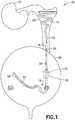
- FIG. 1 there is shown a partial perspective view of a ureteral stent 10 incorporating features of the invention.
- a ureteral stent 10 incorporating features of the invention.
- the invention will be described with reference to the exemplary embodiments shown in the drawings, it should be understood that the invention can be embodied in many alternate forms of embodiments.
- any suitable size, shape or type of elements or materials could be used.
- the ureteral stent 10 comprises a tubular member 12 having a proximal end 14, an opposite distal end 16, and a middle portion 18 between the proximal end 14 and the distal end 16.
- the proximal end 14 is configured to be placed within the renal pelvis 20 of the kidney 22.
- the distal end 16 is configured to be placed within the bladder 24.
- the proximal end 14 comprises a coiled configuration (or shape) having a conical spiral shape 26.
- the conical spiral shape 26 extends away from the middle portion 18 such that the diameter of the conical spiral shape 26 increases as the shape extends away from the middle portion and a first open end 28 of the stent 10 is at substantially the largest diameter portion of the conical spiral shape 26.
- the conical spiral shape 26 of the proximal end 14 is configured to allow for anchoring of the proximal end 14 within the renal pelvis. This provides a retention mechanism which reduces the contact force placed on the pelvis wall (of the renal pelvis 20) by providing increased surface area of contact between the proximal end and the pelvis wall when compared to conventional configurations.
- the middle portion 18 comprises side holes (or openings) 30 extending through a wall of the tubular member.
- the side holes 30 are configured to have smooth edges (or smooth opening surfaces) 32.
- the smooth edges may be provided by any suitable machining or fabrication operation capable of rounding the edges (such as by providing a fillet, blend, corner radius, or rounded corner, at the edges 32).
- the smoothing process may include a punch process wherein during the punching the polymer is melted removing any sharp edges.
- the edges can be post operatively melted with a hot air, flame or hot tool, for example.
- the smooth edges may be provided any suitable edge areas of the holes 32 between an inside diameter and an outside diameter of the tubular member.
- the stent 10 as comprising four side holes 30 at the middle portion 18, one skilled in the art will appreciate that the various exemplary embodiments are not necessarily so limited and that alternate embodiments may comprise any suitable number of side holes.
- the stent may comprise one or more side holes, in other embodiments the stent may comprise five or more side holes, and it should be understood that any number of side holes may be provided.
- the side holes 30 may be provided at any one, or combination of, the proximal end 14, the distal end 16, and/or the middle portion 18 (with any suitable number of side holes at each end 14, 16 or the middle portion 18), including at retention portions or other shaped features of the ends.
- This "smooth" hole configuration is configured to reduce irritation and patient pain.
- the smooth edges are also provided to reduce turbulence of urine flow (as it promotes encrustation).
- This smooth edge configuration of the holes reduces turbulence during flow down the ureter whether it is gravity feed or the peristaltic action of the ureter itself. Additionally, the position of the holes may play a role in urine reflux (discussed further below).
- the stent 10 may further comprise an exterior reflux skirt 34 and/or an interior reflux valve 36 between the middle portion 18 and the distal end 16.
- the exterior reflux skirt 34 surrounds a portion of the tubular member with a general cone shape and is configured to minimize exterior reflux flow.
- the interior reflux valve 36 is configured to provide one way flow through the tubular member (see arrow 38).
- the interior reflux valve 36 may be a duck bill valve, however in alternate embodiments, any suitable type of valve allowing for one way flow may be provided, such as a check valve, for example.
- the distal end 16 comprises a tail portion (or tip portion) 40 configured to be received within the bladder proximate a zone or region called the "Trigon".
- the Trigon has copious nerve endings signaling the need to void the bladder and when voiding is complete. Contact with the trigon zone causes much of the patient's discomfort.
- the tail portion 40 comprises a foam material and is configured such that the tail portion "floats" in water/urine in the bladder (with the foam having a specific gravity ⁇ 1.0, for example) minimizing (or eliminating) contact with the trigon when any urine is present.
- tail portion is described above as having a foam material, one skilled in the art will appreciate the exemplary embodiments are not necessarily so limited, and that alternate embodiments may comprise any suitable material configured to float in the bladder, such as configurations having "trapped" air in the side walls to achieve floating, for example.
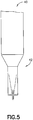
- the tail portion 40 may further comprise a one-way urine flow valve 42 enabling reductions in urine reflux (urine flow back up the ureter to the kidney).
- the configuration of the distal tail 40 including the one-way valve 42 requires no additional components as it comprises a folded tube heat set feature as shown in Fig. 5 .
- the configuration of the one-way urine flow valve 42 may be similar to the configuration of a duck bill valve, however a duck valve may generally be wider than the normal tubular outside diameter (OD) and a 4-wing valve could be smaller than the OD. Multiple wing configurations may also apply in some embodiments.
- the one-way valve 42 substantially eliminates reflux through the stent lumen but not exterior to the stent.
- Figs. 6 and 7 illustrate alternate configurations of the floating tip portion.
- the floating tip portion 140 is similar to the tip portion 40, however in this embodiment the tip portion 140 comprises a tapered portion 142. Additionally, the floating tip portion 240 is similar to the tip portion 40 and comprises a reflux valve 242 which is fitted within an end portion of the tubular member 12.
- an exterior anti-reflux feature 34, 36 may be provided to substantially eliminate the urine flow around the exterior of the stent.
- the combination of the distal valve 42 within the bladder and exterior valve 36 near the midpoint of the stent and providing holes 30 having smooth low turbulence side edges 32 above or on the kidney side of the exterior reflux feature provides for reduction of urine reflux.
- the distal end 16 may comprise a J-hook migration lock 44 configured to prevent migration of the stent due to patient movement.
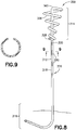
- the stent 300 comprises a distal end 316 similar to the distal end 16 shown in Figs. 1 , 2 , and middle portion 318 similar to the middle portion 18 shown in Figs. 1 , 2 (with holes 330 similar to holes 30 and valve 336 similar to valve 36).
- the tubular member 312 comprises a bend portion 360 which extends to the largest diameter portion of the spiral conical shape 326.
- the conical spiral shape 326 surrounds the tubular member 312 and extends towards the middle portion 318 such that the diameter of the conical spiral shape 326 decreases as the shape extends towards the middle portion 318 and a first open end 328 of the stent 300 is at substantially the smallest diameter portion of the conical spiral shape 326.
- the conical spiral shape 326 is configured to lock the distal end into position, and the top portion of the conical spiral shape (i.e. largest diameter portion) allows a spring action as ureteral contracts.
- the proximal end 414 comprises a dual conical spiral shape 426 having a spring region 462 and an anchor region 464. Similar to the configuration shown in Fig. 8 , the tubular member 412 comprises a bend portion 460. However from the bend portion, the spring region 462 of the conical spiral shape increases in a direction away from the bend portion and the largest diameter portion of the spiral conical shape 426 is between the spring region 462 and the anchor region 464.
- the conical spiral shape 426 surrounds the tubular member 412 and extends towards the middle portion 418 such that the diameter of the conical spiral shape 426 decreases as the shape extends from the spring region towards the middle portion 318 and a first open end 428 of the stent 400 is at substantially the smallest diameter portion of the conical spiral shape 426.
- the dual conical spring shape may be provided with a heat set fixture comprising two conical regions 562, 564 which correspond to the regions 462, 464, of the conical spiral shape 426 (see Fig. 11 ).
- a heat set fixture comprising two conical regions 562, 564 which correspond to the regions 462, 464, of the conical spiral shape 426 (see Fig. 11 ).
- the fixture shown in Fig. 11 is merely exemplary and any suitable type of fixture may be provided.
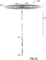
- the proximal end 614 comprises a bend portion 660 and a first open end 628.
- the proximal end 614 comprises a coiled shape 626 which lies substantially in a plane orthogonal to the middle portion 618 of the stent 600.
- the coiled shape 626 surrounds the end of the tubular member 612 in a coiled/spiraled fashion.
- the proximal end 714 comprises a bend portion 760 and a first open end 728.
- the proximal end 714 comprises a coiled section having a general spherical or bulb-like shape 726.
- the coiled spherical or bulb-like shape 726 surrounds a portion at the end of the tubular member 712 of the stent 700.
- the stent 800 comprises a distal end 816 similar to the distal end 316 shown in Fig. 8 , and middle portion 818 similar to the middle portion 318 shown in Fig. 8 (with holes 830 similar to holes 330 and valve 836 similar to valve 336).
- the spiral conical shape 826 comprises a reverse spiral (see Fig. 16 ) compared to the configuration shown in Fig. 8 (in other words, when viewed from the top, the spiral has a 'clockwise' configuration from largest diameter to smallest diameter, whereas the configuration in Fig.
- Fig. 16 illustrates (see arrows) where holes 830 are also provided on the internal surface (i.e. surface facing the tubular member 812) of the conical spiral shape 826.
- the holes 830 may be provided at any suitable surface portion of the conical spiral shape 826.
- Figs. 17-20 illustrate various exemplary embodiments of the exterior reflux skirt 34 (shown in Fig. 4 ), however the reflux skirt (or valve) 934, 934', are configured to actuate, and in some embodiments shorten, over a narrowed portion of the tubular member 912. As the exterior valve 934, 934' shortens, it expands radially creating a larger portion of the stent to therefore block exterior liquid flow.
- Figs. 21, 22 illustrate an exemplary embodiment of a proximal portion 1014 that is configured to be adjustable to fit within the renal pelvis of various patients.
- the adjustable portions illustrated in Figs. 21, 22 may comprise any suitable configuration.
- any one or more of the exemplary embodiments provide significant advantages over conventional configurations having side holes which are typically punched or drilled through the wall resulting in a sharp edge(s).
- the exemplary embodiments disclosed herein provide a smooth hole edge configuration (providing smooth exterior ports) which reduces patient pain and provides greater comfort.
- a ureteral stent comprising: a proximal end comprising a retention feature having a coiled shape; a distal end opposite the proximal end; and a middle portion between the proximal end and the distal end.
- components of the invention can be operationally coupled or connected and that any number or combination of intervening elements can exist (including no intervening elements).
- the connections can be direct or indirect and additionally there can merely be a functional relationship between components.
Landscapes
- Health & Medical Sciences (AREA)
- Life Sciences & Earth Sciences (AREA)
- Engineering & Computer Science (AREA)
- Biomedical Technology (AREA)
- Veterinary Medicine (AREA)
- Public Health (AREA)
- General Health & Medical Sciences (AREA)
- Heart & Thoracic Surgery (AREA)
- Animal Behavior & Ethology (AREA)
- Anesthesiology (AREA)
- Hematology (AREA)
- Biophysics (AREA)
- Pulmonology (AREA)
- Otolaryngology (AREA)
- Ophthalmology & Optometry (AREA)
- Urology & Nephrology (AREA)
- Neurology (AREA)
- Cardiology (AREA)
- Oral & Maxillofacial Surgery (AREA)
- Transplantation (AREA)
- Vascular Medicine (AREA)
- Prostheses (AREA)
- Media Introduction/Drainage Providing Device (AREA)
Abstract
Description
- The invention relates to a ureteral stent and more specifically relates to a comfort ureteral stent.
- A ureter is a tubular passageway in the body that conveys urine from a kidney to a bladder. Ureteral stents are used to facilitate urinary drainage from the kidney to the bladder in patients having a ureteral obstruction or injury, or to protect the integrity of the ureter in a variety of surgical manipulations. Ureteral stents are typically about 30 cm long, hollow catheter-like devices made from a polymer and placed within the ureter with a distal end residing in the kidney and a proximal end residing in the bladder.
- Accordingly, there is a need to provide improved and reliable ureteral stent configurations that are configured for increased patient comfort.
- In accordance with one aspect of the invention, a ureteral stent is disclosed. The ureteral stent includes a proximal end, a distal end, and a middle portion. The proximal end includes a retention feature having a coiled shape. The distal end is opposite the proximal end. The middle portion is between the proximal end and the distal end.
- The foregoing aspects and other features of the invention are explained in the following description, taken in connection with the accompanying drawings, wherein:
-
Fig. 1 is a partial perspective view of ureteral stent (within the body of a patient) incorporating features of the invention; -
Fig. 2 is another perspective view of the ureteral stent shown inFig. 1 ; -
Fig. 3 is a section view of the indicated section line inFig. 2 ; -
Fig. 4 is an enlarged view of the indicated portion inFig. 2 ; -
Fig. 5 is a partial view of a tail portion of the ureteral stent shown inFig. 1 ; -
Figs. 6 and 7 are perspective views of alternate configurations of a floating tip portion of the ureteral stent shown inFig. 1 ; -
Fig. 8 is a perspective view of another example ureteral stent incorporating features of the invention; -
Fig. 9 is a section view of the indicated section line inFig. 8 ; -
Fig. 10 is an alternate embodiment of the proximal end shown inFig. 8 ; -
Fig. 11 is a perspective view showing a fixture corresponding to the proximal end shown inFig. 10 ; -
Fig. 12 is another alternate embodiment of the proximal end shown inFig. 8 ; -
Fig. 13 is another alternate embodiment of the proximal end shown inFig. 8 ; -
Fig. 14 is a perspective view of another example ureteral stent incorporating features of the invention; -
Fig. 15 is a section view of the indicated section line inFig. 14 ; -
Fig. 16 is a top view of the ureteral stent shown inFig. 14 ; -
Figs. 17-20 are alternate exterior valve configurations according to various embodiments of the ureteral stent; and -
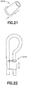
Figs. 21, 22 are alternate proximal portion configurations according to various embodiments of the ureteral stent. - Referring to
Fig. 1 , there is shown a partial perspective view of aureteral stent 10 incorporating features of the invention. Although the invention will be described with reference to the exemplary embodiments shown in the drawings, it should be understood that the invention can be embodied in many alternate forms of embodiments. In addition, any suitable size, shape or type of elements or materials could be used. - The
ureteral stent 10 comprises atubular member 12 having aproximal end 14, an oppositedistal end 16, and amiddle portion 18 between theproximal end 14 and thedistal end 16. Theproximal end 14 is configured to be placed within therenal pelvis 20 of thekidney 22. Thedistal end 16 is configured to be placed within thebladder 24. - Referring now also to
Fig. 2 , theproximal end 14 comprises a coiled configuration (or shape) having a conicalspiral shape 26. The conicalspiral shape 26 extends away from themiddle portion 18 such that the diameter of the conicalspiral shape 26 increases as the shape extends away from the middle portion and a firstopen end 28 of thestent 10 is at substantially the largest diameter portion of the conicalspiral shape 26. - The conical
spiral shape 26 of theproximal end 14 is configured to allow for anchoring of theproximal end 14 within the renal pelvis. This provides a retention mechanism which reduces the contact force placed on the pelvis wall (of the renal pelvis 20) by providing increased surface area of contact between the proximal end and the pelvis wall when compared to conventional configurations. - The
middle portion 18 comprises side holes (or openings) 30 extending through a wall of the tubular member. Referring now also to section view 3-3, theside holes 30 are configured to have smooth edges (or smooth opening surfaces) 32. The smooth edges may be provided by any suitable machining or fabrication operation capable of rounding the edges (such as by providing a fillet, blend, corner radius, or rounded corner, at the edges 32). According to various exemplary embodiments, the smoothing process may include a punch process wherein during the punching the polymer is melted removing any sharp edges. Also, the edges can be post operatively melted with a hot air, flame or hot tool, for example. The smooth edges may be provided any suitable edge areas of theholes 32 between an inside diameter and an outside diameter of the tubular member. - It should be noted that although various figures illustrate the
stent 10 as comprising fourside holes 30 at themiddle portion 18, one skilled in the art will appreciate that the various exemplary embodiments are not necessarily so limited and that alternate embodiments may comprise any suitable number of side holes. For example in some embodiments, the stent may comprise one or more side holes, in other embodiments the stent may comprise five or more side holes, and it should be understood that any number of side holes may be provided. Additionally, theside holes 30 may be provided at any one, or combination of, theproximal end 14, thedistal end 16, and/or the middle portion 18 (with any suitable number of side holes at eachend - As the urethra elongates and contracts with bladder voiding action, this movement results in the ureter rubbing against the
edges 32 of theholes 30. This "smooth" hole configuration is configured to reduce irritation and patient pain. In addition to the smooth aspect of the hole edge configuration for patient comfort, the smooth edges are also provided to reduce turbulence of urine flow (as it promotes encrustation). This smooth edge configuration of the holes reduces turbulence during flow down the ureter whether it is gravity feed or the peristaltic action of the ureter itself. Additionally, the position of the holes may play a role in urine reflux (discussed further below). - According to various exemplary embodiments, the
stent 10 may further comprise anexterior reflux skirt 34 and/or aninterior reflux valve 36 between themiddle portion 18 and thedistal end 16. Theexterior reflux skirt 34 surrounds a portion of the tubular member with a general cone shape and is configured to minimize exterior reflux flow. Theinterior reflux valve 36 is configured to provide one way flow through the tubular member (see arrow 38). According to various exemplary embodiments, theinterior reflux valve 36 may be a duck bill valve, however in alternate embodiments, any suitable type of valve allowing for one way flow may be provided, such as a check valve, for example. - The
distal end 16 comprises a tail portion (or tip portion) 40 configured to be received within the bladder proximate a zone or region called the "Trigon". The Trigon has copious nerve endings signaling the need to void the bladder and when voiding is complete. Contact with the trigon zone causes much of the patient's discomfort. Thetail portion 40 comprises a foam material and is configured such that the tail portion "floats" in water/urine in the bladder (with the foam having a specific gravity <1.0, for example) minimizing (or eliminating) contact with the trigon when any urine is present. Although the tail portion is described above as having a foam material, one skilled in the art will appreciate the exemplary embodiments are not necessarily so limited, and that alternate embodiments may comprise any suitable material configured to float in the bladder, such as configurations having "trapped" air in the side walls to achieve floating, for example. - According to various exemplary embodiments, the
tail portion 40 may further comprise a one-way urine flowvalve 42 enabling reductions in urine reflux (urine flow back up the ureter to the kidney). The configuration of thedistal tail 40 including the one-way valve 42 requires no additional components as it comprises a folded tube heat set feature as shown inFig. 5 . According to various exemplary embodiments, the configuration of the one-way urine flowvalve 42 may be similar to the configuration of a duck bill valve, however a duck valve may generally be wider than the normal tubular outside diameter (OD) and a 4-wing valve could be smaller than the OD. Multiple wing configurations may also apply in some embodiments. In situ, the one-way valve 42 substantially eliminates reflux through the stent lumen but not exterior to the stent. -
Figs. 6 and 7 illustrate alternate configurations of the floating tip portion. The floatingtip portion 140 is similar to thetip portion 40, however in this embodiment thetip portion 140 comprises a taperedportion 142. Additionally, the floatingtip portion 240 is similar to thetip portion 40 and comprises areflux valve 242 which is fitted within an end portion of thetubular member 12. - According to the various exemplary embodiments, an
exterior anti-reflux feature distal valve 42 within the bladder andexterior valve 36 near the midpoint of the stent and providingholes 30 having smooth low turbulence side edges 32 above or on the kidney side of the exterior reflux feature provides for reduction of urine reflux. Additionally, in some embodiments thedistal end 16 may comprise a J-hook migration lock 44 configured to prevent migration of the stent due to patient movement. - Referring now also to
Fig. 8 another embodiment of the stent is shown. In this embodiment, thestent 300 comprises adistal end 316 similar to thedistal end 16 shown inFigs. 1 ,2 , andmiddle portion 318 similar to themiddle portion 18 shown inFigs. 1 ,2 (withholes 330 similar toholes 30 andvalve 336 similar to valve 36). However, at theproximal end 314 thetubular member 312 comprises abend portion 360 which extends to the largest diameter portion of the spiralconical shape 326. Theconical spiral shape 326 surrounds thetubular member 312 and extends towards themiddle portion 318 such that the diameter of theconical spiral shape 326 decreases as the shape extends towards themiddle portion 318 and a firstopen end 328 of thestent 300 is at substantially the smallest diameter portion of theconical spiral shape 326. In this embodiment, theconical spiral shape 326 is configured to lock the distal end into position, and the top portion of the conical spiral shape (i.e. largest diameter portion) allows a spring action as ureteral contracts. - Referring now also to
Fig. 10 , another alternate embodiment of the proximal end is shown. Theproximal end 414 comprises a dualconical spiral shape 426 having aspring region 462 and ananchor region 464. Similar to the configuration shown inFig. 8 , thetubular member 412 comprises abend portion 460. However from the bend portion, thespring region 462 of the conical spiral shape increases in a direction away from the bend portion and the largest diameter portion of the spiralconical shape 426 is between thespring region 462 and theanchor region 464. Theconical spiral shape 426 surrounds thetubular member 412 and extends towards themiddle portion 418 such that the diameter of theconical spiral shape 426 decreases as the shape extends from the spring region towards themiddle portion 318 and a firstopen end 428 of thestent 400 is at substantially the smallest diameter portion of theconical spiral shape 426. - According to various exemplary embodiments the dual conical spring shape may be provided with a heat set fixture comprising two
conical regions regions Fig. 11 ). However, it should be noted that the fixture shown inFig. 11 is merely exemplary and any suitable type of fixture may be provided. - Referring now also to
Fig. 12 , another alternate embodiment of the proximal end is shown. Similar to the proximal end shown inFig. 8 , theproximal end 614 comprises abend portion 660 and a firstopen end 628. However in this embodiment, theproximal end 614 comprises acoiled shape 626 which lies substantially in a plane orthogonal to themiddle portion 618 of thestent 600. Thecoiled shape 626 surrounds the end of thetubular member 612 in a coiled/spiraled fashion. - Referring now also to
Fig. 13 , another alternate embodiment of the proximal end is shown. Similar to the proximal end shown inFig. 8 , theproximal end 714 comprises abend portion 760 and a firstopen end 728. However in this embodiment, theproximal end 714 comprises a coiled section having a general spherical or bulb-like shape 726. The coiled spherical or bulb-like shape 726 surrounds a portion at the end of thetubular member 712 of thestent 700. - Referring now also to
Fig. 14 another embodiment of the stent is shown. In this embodiment, thestent 800 comprises adistal end 816 similar to thedistal end 316 shown inFig. 8 , andmiddle portion 818 similar to themiddle portion 318 shown inFig. 8 (withholes 830 similar toholes 330 andvalve 836 similar to valve 336). However, at theproximal end 814 the spiralconical shape 826 comprises a reverse spiral (seeFig. 16 ) compared to the configuration shown inFig. 8 (in other words, when viewed from the top, the spiral has a 'clockwise' configuration from largest diameter to smallest diameter, whereas the configuration inFig. 8 when viewed from the top, the spiral has a 'counter-clockwise' configuration from largest diameter to smallest diameter). Additionally,Fig. 16 illustrates (see arrows) whereholes 830 are also provided on the internal surface (i.e. surface facing the tubular member 812) of theconical spiral shape 826. However, it should be noted that theholes 830 may be provided at any suitable surface portion of theconical spiral shape 826. -
Figs. 17-20 illustrate various exemplary embodiments of the exterior reflux skirt 34 (shown inFig. 4 ), however the reflux skirt (or valve) 934, 934', are configured to actuate, and in some embodiments shorten, over a narrowed portion of thetubular member 912. As theexterior valve 934, 934' shortens, it expands radially creating a larger portion of the stent to therefore block exterior liquid flow. -
Figs. 21, 22 illustrate an exemplary embodiment of aproximal portion 1014 that is configured to be adjustable to fit within the renal pelvis of various patients. However, it should be noted that the adjustable portions illustrated inFigs. 21, 22 may comprise any suitable configuration. - Technical effects of any one or more of the exemplary embodiments provide significant advantages over conventional configurations having side holes which are typically punched or drilled through the wall resulting in a sharp edge(s). The exemplary embodiments disclosed herein provide a smooth hole edge configuration (providing smooth exterior ports) which reduces patient pain and provides greater comfort.
- Below are provided further descriptions of various non-limiting, exemplary embodiments. The below-described exemplary embodiments may be practiced in conjunction with one or more other aspects or exemplary embodiments. That is, the exemplary embodiments of the invention, such as those described immediately below, may be implemented, practiced or utilized in any combination (e.g., any combination that is suitable, practicable and/or feasible) and are not limited only to those combinations described herein and/or included in the appended claims.
- In one exemplary embodiment, a ureteral stent comprising: a proximal end comprising a retention feature having a coiled shape; a distal end opposite the proximal end; and a middle portion between the proximal end and the distal end.
- A ureteral stent as above, wherein the middle portion comprises at least one opening having smooth opening surfaces.
- A ureteral stent as above, wherein the at least one opening comprises rounded edges.
- A ureteral stent as above, wherein the coiled shape is a spiral shape.
- A ureteral stent as above, wherein the retention feature has a conical coiled shape.
- A ureteral stent as above, wherein the coiled shape retention feature lies substantially on a plane orthogonal to the plane the middle portion lies on.
- A ureteral stent as above, wherein the retention feature comprises a general spherical shape.
- A ureteral stent as above, wherein the distal end comprises a tail portion configured to float.
- A ureteral stent as above, wherein the retention feature comprises a dual conical spiral shape.
- A ureteral stent as above, further comprising a one-way valve between the middle portion and the distal end.
- A ureteral stent as above, further comprising a one-way valve at the distal end.
- A ureteral stent as above, wherein the distal end comprises a retention feature.
- It should be understood that components of the invention can be operationally coupled or connected and that any number or combination of intervening elements can exist (including no intervening elements). The connections can be direct or indirect and additionally there can merely be a functional relationship between components.
- It should be understood that the foregoing description is only illustrative of the invention. Various alternatives and modifications can be devised by those skilled in the art without departing from the invention. Accordingly, the invention is intended to embrace all such alternatives, modifications and variances which fall within the scope of the appended claims.
Claims (12)
- A ureteral stent comprising:a proximal end comprising a retention feature having a coiled shape;a distal end opposite the proximal end; anda middle portion between the proximal end and the distal end.
- The ureteral stent of claim 1, wherein the middle portion comprises at least one opening having smooth opening surfaces.
- The ureteral stent of claim 2, wherein the at least one opening comprises rounded edges.
- The ureteral stent of claim 1, wherein the coiled shape is a spiral shape.
- The ureteral stent of claim 1, wherein the retention feature has a conical coiled shape.
- The ureteral stent of claim 5, wherein the coiled shape retention feature lies substantially on a plane orthogonal to the plane the middle portion lies on.
- The ureteral stent of claim 1, wherein the retention feature comprises a general spherical shape.
- The ureteral stent of claim 1, wherein the distal end comprises a tail portion configured to float.
- The ureteral stent of claim 1, wherein the retention feature comprises a dual conical spiral shape.
- The ureteral stent of claim 1, further comprising a one-way valve between the middle portion and the distal end.
- The ureteral stent of claim 1, further comprising a one-way valve at the distal end.
- The ureteral stent of claim 1, wherein the distal end comprises a retention feature.
Priority Applications (1)
| Application Number | Priority Date | Filing Date | Title |
|---|---|---|---|
| EP21200605.0A EP3970775A1 (en) | 2017-07-28 | 2018-07-02 | Ureteral stent |
Applications Claiming Priority (1)
| Application Number | Priority Date | Filing Date | Title |
|---|---|---|---|
| US15/662,973 US10881842B2 (en) | 2017-07-28 | 2017-07-28 | Ureteral stent |
Related Child Applications (1)
| Application Number | Title | Priority Date | Filing Date |
|---|---|---|---|
| EP21200605.0A Division EP3970775A1 (en) | 2017-07-28 | 2018-07-02 | Ureteral stent |
Publications (2)
| Publication Number | Publication Date |
|---|---|
| EP3434308A1 true EP3434308A1 (en) | 2019-01-30 |
| EP3434308B1 EP3434308B1 (en) | 2021-10-06 |
Family
ID=62841989
Family Applications (2)
| Application Number | Title | Priority Date | Filing Date |
|---|---|---|---|
| EP18181191.0A Active EP3434308B1 (en) | 2017-07-28 | 2018-07-02 | Ureteral stent |
| EP21200605.0A Pending EP3970775A1 (en) | 2017-07-28 | 2018-07-02 | Ureteral stent |
Family Applications After (1)
| Application Number | Title | Priority Date | Filing Date |
|---|---|---|---|
| EP21200605.0A Pending EP3970775A1 (en) | 2017-07-28 | 2018-07-02 | Ureteral stent |
Country Status (5)
| Country | Link |
|---|---|
| US (3) | US10881842B2 (en) |
| EP (2) | EP3434308B1 (en) |
| JP (1) | JP7849134B2 (en) |
| CN (2) | CN109303627B (en) |
| ES (1) | ES2901637T3 (en) |
Cited By (1)
| Publication number | Priority date | Publication date | Assignee | Title |
|---|---|---|---|---|
| US10881842B2 (en) | 2017-07-28 | 2021-01-05 | Gyrus Acmi, Inc. | Ureteral stent |
Families Citing this family (14)
| Publication number | Priority date | Publication date | Assignee | Title |
|---|---|---|---|---|
| US10493232B2 (en) | 2015-07-20 | 2019-12-03 | Strataca Systems Limited | Ureteral catheters, bladder catheters, systems, kits and methods for inducing negative pressure to increase renal function |
| US12064567B2 (en) | 2015-07-20 | 2024-08-20 | Roivios Limited | Percutaneous urinary catheter |
| US11541205B2 (en) | 2015-07-20 | 2023-01-03 | Roivios Limited | Coated urinary catheter or ureteral stent and method |
| US10918827B2 (en) | 2015-07-20 | 2021-02-16 | Strataca Systems Limited | Catheter device and method for inducing negative pressure in a patient's bladder |
| US11040172B2 (en) | 2015-07-20 | 2021-06-22 | Strataca Systems Limited | Ureteral and bladder catheters and methods of inducing negative pressure to increase renal perfusion |
| CN112691278B (en) | 2015-07-20 | 2024-03-22 | 罗维奥斯有限公司 | Ureter and bladder catheter and method of introducing negative pressure to increase renal perfusion |
| US10926062B2 (en) | 2015-07-20 | 2021-02-23 | Strataca Systems Limited | Ureteral and bladder catheters and methods of inducing negative pressure to increase renal perfusion |
| WO2019038730A1 (en) | 2017-08-25 | 2019-02-28 | Strataca Systems Limited | Indwelling pump for facilitating removal of urine from the urinary tract |
| US20200268947A1 (en) * | 2017-08-25 | 2020-08-27 | Strataca Systems Limited | Pump Assembly and System for Inducing Negative Pressure in a Portion of a Urinary Tract of a Patient |
| EP3581232B1 (en) * | 2018-06-11 | 2021-02-17 | Dentsply IH AB | Urethral stent and bladder control assembly comprising such a urethral stent |
| CN112089900B (en) * | 2020-09-24 | 2025-07-15 | 张斌 | An anti-blocking closed irrigation drainage tube for treating deep spinal infection |
| KR102520440B1 (en) * | 2020-12-15 | 2023-04-11 | 한양대학교 산학협력단 | Antireflux ureteral stent |
| US12472301B2 (en) | 2021-08-13 | 2025-11-18 | 3Ive Labs, Llc | Negative pressure therapy system and methods |
| US20240308032A1 (en) * | 2023-03-19 | 2024-09-19 | Jonas Adrian LaPointe | Apparatus, system, and methods for facilitating rotation of connector fittings |
Citations (6)
| Publication number | Priority date | Publication date | Assignee | Title |
|---|---|---|---|---|
| US20030109930A1 (en) * | 2001-12-11 | 2003-06-12 | Scott Bluni | Ureteral stents and related methods |
| US20040059279A1 (en) * | 1995-11-07 | 2004-03-25 | Scimed Life Systems, Inc. | Ureteral stent for improved patient comfort |
| DE202006017068U1 (en) * | 2006-06-07 | 2007-08-02 | Mosenkis, Mykhaylo | Implantable catheter |
| WO2012019155A1 (en) * | 2010-08-05 | 2012-02-09 | Taris Biomedical, Inc. | Ureteral stent drug delivery device, kit, and method |
| WO2014159848A1 (en) * | 2013-03-14 | 2014-10-02 | The General Hospital Corporation | System and method for use of flexible anti-reflux ureteral stent |
| US9186480B2 (en) * | 2007-06-20 | 2015-11-17 | Unomedical A/S | Apparatus for making a catheter |
Family Cites Families (34)
| Publication number | Priority date | Publication date | Assignee | Title |
|---|---|---|---|---|
| US4738667A (en) | 1986-11-04 | 1988-04-19 | Galloway Niall T M | Preformed catheter assembly |
| US6849069B1 (en) * | 1995-11-07 | 2005-02-01 | Boston Scientitfic Corporation | Medical device with tail(s) for assisting flow of urine |
| US6676624B2 (en) * | 2001-12-20 | 2004-01-13 | Scimed Life Systems, Inc. | Drainage devices and methods |
| US8328877B2 (en) * | 2002-03-19 | 2012-12-11 | Boston Scientific Scimed, Inc. | Stent retention element and related methods |
| US20040087886A1 (en) * | 2002-10-30 | 2004-05-06 | Scimed Life Systems, Inc. | Linearly expandable ureteral stent |
| US7044981B2 (en) * | 2003-01-22 | 2006-05-16 | Boston Scientific Scimed, Inc. | Ureteral stent configured for improved patient comfort and aftercare |
| GB0409031D0 (en) | 2004-04-23 | 2004-05-26 | Ravi P K | Stents |
| US7507218B2 (en) * | 2004-04-26 | 2009-03-24 | Gyrus Acmi, Inc. | Stent with flexible elements |
| JP3816092B1 (en) * | 2005-08-03 | 2006-08-30 | ベクトル株式会社 | Ureteral stent |
| WO2007062661A2 (en) | 2005-12-02 | 2007-06-07 | Pnn Medical A/S | A stent |
| US8048168B2 (en) * | 2006-06-16 | 2011-11-01 | Boston Scientific Scimed, Inc. | Partially soluble implantable or insertable medical devices |
| WO2008121311A1 (en) * | 2007-03-29 | 2008-10-09 | Boston Scientific Scimed, Inc. | Catheter assembly including coiled internal bolster |
| US9333063B2 (en) * | 2008-05-09 | 2016-05-10 | Boston Scientific Scimed, Inc. | Antimicrobial medical devices |
| BRPI1012680B8 (en) * | 2009-06-26 | 2021-06-22 | Coloplast As | urinary catheter, and, method for injection molding a urinary catheter |
| CN201759704U (en) * | 2010-08-06 | 2011-03-16 | 中国人民解放军第三军医大学第一附属医院 | Ureteral stent tube |
| US8920513B2 (en) * | 2010-08-27 | 2014-12-30 | Thomas W. Rickner | Anti-refluxive and trigone sparing internal ureteral stent |
| EP2858710B1 (en) | 2012-06-08 | 2020-10-07 | University Hospitals Health System Inc. | Ureteral stent for placement in a kidney and bladder |
| CN203749985U (en) * | 2014-01-03 | 2014-08-06 | 江苏省人民医院 | Anti-backflow ureter bracket tube |
| CN204158869U (en) * | 2014-01-15 | 2015-02-18 | 江苏省人民医院 | Double helical form anti-reflux support tube of ureter |
| CN105960219B (en) * | 2014-04-04 | 2017-09-01 | 捷锐士阿希迈公司(以奥林巴斯美国外科技术名义) | Ureter bracket with antimigration features |
| CN204208159U (en) * | 2014-09-02 | 2015-03-18 | 中国人民解放军第三军医大学第三附属医院 | A kind of ureter rack tube |
| US20160199170A1 (en) * | 2015-01-13 | 2016-07-14 | Cook Medical Technologies Llc | Ureteral stent with sideports |
| US9775698B2 (en) | 2015-01-23 | 2017-10-03 | Spinal Singularity, Inc. | Urinary prosthesis systems |
| CN204521068U (en) * | 2015-01-29 | 2015-08-05 | 深圳市康医博科技发展有限公司 | A kind of counterflow-preventing ureter urethral catheterization support |
| CN112691278B (en) * | 2015-07-20 | 2024-03-22 | 罗维奥斯有限公司 | Ureter and bladder catheter and method of introducing negative pressure to increase renal perfusion |
| US11484421B2 (en) * | 2016-01-20 | 2022-11-01 | Boston Scientific Scimed, Inc. | Medical device with adjustable length |
| WO2017192145A1 (en) * | 2016-05-06 | 2017-11-09 | University Hospitals Health Systems, Inc. | Ureteral stent |
| CN106137478B (en) * | 2016-07-22 | 2018-08-14 | 成都嘉宝祥生物科技有限公司 | A kind of ureter rack tube |
| US11033412B2 (en) * | 2016-08-12 | 2021-06-15 | Gyrus Acmi, Inc. | Solid wire ureteral stent |
| DE102016125556A1 (en) * | 2016-12-23 | 2018-06-28 | Georg-August-Universität Göttingen Stiftung Öffentlichen Rechts, Universitätsmedizin | Sucker tip for gentle suction of blood from surgical fields |
| US10881842B2 (en) | 2017-07-28 | 2021-01-05 | Gyrus Acmi, Inc. | Ureteral stent |
| US10933227B2 (en) * | 2017-12-01 | 2021-03-02 | Gyrus Acmi, Inc. | Ureteral stent |
| US11039914B2 (en) * | 2018-10-22 | 2021-06-22 | Sevro Technologies Llc | Variable length stent |
| AU2020337330B2 (en) * | 2019-08-23 | 2023-02-02 | Boston Scientific Scimed, Inc. | Devices, systems, and methods for delivering a stent |
-
2017
- 2017-07-28 US US15/662,973 patent/US10881842B2/en active Active
-
2018
- 2018-06-19 CN CN201810627898.3A patent/CN109303627B/en active Active
- 2018-06-19 CN CN202310017498.1A patent/CN116035786A/en active Pending
- 2018-07-02 EP EP18181191.0A patent/EP3434308B1/en active Active
- 2018-07-02 EP EP21200605.0A patent/EP3970775A1/en active Pending
- 2018-07-02 JP JP2018125832A patent/JP7849134B2/en active Active
- 2018-07-02 ES ES18181191T patent/ES2901637T3/en active Active
-
2020
- 2020-07-15 US US16/929,672 patent/US11969568B2/en active Active
-
2023
- 2023-12-15 US US18/541,141 patent/US20240189555A1/en active Pending
Patent Citations (6)
| Publication number | Priority date | Publication date | Assignee | Title |
|---|---|---|---|---|
| US20040059279A1 (en) * | 1995-11-07 | 2004-03-25 | Scimed Life Systems, Inc. | Ureteral stent for improved patient comfort |
| US20030109930A1 (en) * | 2001-12-11 | 2003-06-12 | Scott Bluni | Ureteral stents and related methods |
| DE202006017068U1 (en) * | 2006-06-07 | 2007-08-02 | Mosenkis, Mykhaylo | Implantable catheter |
| US9186480B2 (en) * | 2007-06-20 | 2015-11-17 | Unomedical A/S | Apparatus for making a catheter |
| WO2012019155A1 (en) * | 2010-08-05 | 2012-02-09 | Taris Biomedical, Inc. | Ureteral stent drug delivery device, kit, and method |
| WO2014159848A1 (en) * | 2013-03-14 | 2014-10-02 | The General Hospital Corporation | System and method for use of flexible anti-reflux ureteral stent |
Cited By (2)
| Publication number | Priority date | Publication date | Assignee | Title |
|---|---|---|---|---|
| US10881842B2 (en) | 2017-07-28 | 2021-01-05 | Gyrus Acmi, Inc. | Ureteral stent |
| US11969568B2 (en) | 2017-07-28 | 2024-04-30 | Gyrus Acmi, Inc. | Ureteral stent |
Also Published As
| Publication number | Publication date |
|---|---|
| JP7849134B2 (en) | 2026-04-21 |
| ES2901637T3 (en) | 2022-03-23 |
| JP2019025315A (en) | 2019-02-21 |
| US20240189555A1 (en) | 2024-06-13 |
| US20200345990A1 (en) | 2020-11-05 |
| CN109303627A (en) | 2019-02-05 |
| EP3434308B1 (en) | 2021-10-06 |
| CN109303627B (en) | 2023-01-24 |
| CN116035786A (en) | 2023-05-02 |
| EP3970775A1 (en) | 2022-03-23 |
| US20190030303A1 (en) | 2019-01-31 |
| US11969568B2 (en) | 2024-04-30 |
| US10881842B2 (en) | 2021-01-05 |
Similar Documents
| Publication | Publication Date | Title |
|---|---|---|
| US20240189555A1 (en) | Ureteral Stent | |
| US7041139B2 (en) | Ureteral stents and related methods | |
| US11278436B2 (en) | Ureteral stent for placement in a kidney and bladder | |
| US6764519B2 (en) | Ureteral stent | |
| EP3129097B1 (en) | Ureteral stents | |
| EP1434616B1 (en) | Anti-reflux drainage devices and methods | |
| US20090125120A1 (en) | Drainage Devices | |
| SE454050B (en) | DRAIN FOR DIRECTORS | |
| CN116099113B (en) | Device for percutaneous interventional treatment of hydrocephalus with a one-way valve | |
| JP2020531149A5 (en) | ||
| CN1895694A (en) | Subarachnoid epidural shunt | |
| JP2009538166A (en) | Prostate stent | |
| US20160038273A1 (en) | System and method for use of flexible anti-reflux ureteral stent | |
| JP2020157059A (en) | Perfusion tube |
Legal Events
| Date | Code | Title | Description |
|---|---|---|---|
| PUAI | Public reference made under article 153(3) epc to a published international application that has entered the european phase |
Free format text: ORIGINAL CODE: 0009012 |
|
| STAA | Information on the status of an ep patent application or granted ep patent |
Free format text: STATUS: THE APPLICATION HAS BEEN PUBLISHED |
|
| AK | Designated contracting states |
Kind code of ref document: A1 Designated state(s): AL AT BE BG CH CY CZ DE DK EE ES FI FR GB GR HR HU IE IS IT LI LT LU LV MC MK MT NL NO PL PT RO RS SE SI SK SM TR |
|
| AX | Request for extension of the european patent |
Extension state: BA ME |
|
| STAA | Information on the status of an ep patent application or granted ep patent |
Free format text: STATUS: REQUEST FOR EXAMINATION WAS MADE |
|
| 17P | Request for examination filed |
Effective date: 20190329 |
|
| RBV | Designated contracting states (corrected) |
Designated state(s): AL AT BE BG CH CY CZ DE DK EE ES FI FR GB GR HR HU IE IS IT LI LT LU LV MC MK MT NL NO PL PT RO RS SE SI SK SM TR |
|
| STAA | Information on the status of an ep patent application or granted ep patent |
Free format text: STATUS: EXAMINATION IS IN PROGRESS |
|
| 17Q | First examination report despatched |
Effective date: 20200420 |
|
| GRAP | Despatch of communication of intention to grant a patent |
Free format text: ORIGINAL CODE: EPIDOSNIGR1 |
|
| STAA | Information on the status of an ep patent application or granted ep patent |
Free format text: STATUS: GRANT OF PATENT IS INTENDED |
|
| INTG | Intention to grant announced |
Effective date: 20210504 |
|
| GRAS | Grant fee paid |
Free format text: ORIGINAL CODE: EPIDOSNIGR3 |
|
| GRAA | (expected) grant |
Free format text: ORIGINAL CODE: 0009210 |
|
| STAA | Information on the status of an ep patent application or granted ep patent |
Free format text: STATUS: THE PATENT HAS BEEN GRANTED |
|
| AK | Designated contracting states |
Kind code of ref document: B1 Designated state(s): AL AT BE BG CH CY CZ DE DK EE ES FI FR GB GR HR HU IE IS IT LI LT LU LV MC MK MT NL NO PL PT RO RS SE SI SK SM TR |
|
| REG | Reference to a national code |
Ref country code: GB Ref legal event code: FG4D |
|
| REG | Reference to a national code |
Ref country code: CH Ref legal event code: EP Ref country code: AT Ref legal event code: REF Ref document number: 1435699 Country of ref document: AT Kind code of ref document: T Effective date: 20211015 |
|
| REG | Reference to a national code |
Ref country code: DE Ref legal event code: R096 Ref document number: 602018024513 Country of ref document: DE |
|
| REG | Reference to a national code |
Ref country code: IE Ref legal event code: FG4D |
|
| REG | Reference to a national code |
Ref country code: LT Ref legal event code: MG9D |
|
| REG | Reference to a national code |
Ref country code: NL Ref legal event code: MP Effective date: 20211006 |
|
| REG | Reference to a national code |
Ref country code: AT Ref legal event code: MK05 Ref document number: 1435699 Country of ref document: AT Kind code of ref document: T Effective date: 20211006 |
|
| REG | Reference to a national code |
Ref country code: ES Ref legal event code: FG2A Ref document number: 2901637 Country of ref document: ES Kind code of ref document: T3 Effective date: 20220323 |
|
| PG25 | Lapsed in a contracting state [announced via postgrant information from national office to epo] |
Ref country code: RS Free format text: LAPSE BECAUSE OF FAILURE TO SUBMIT A TRANSLATION OF THE DESCRIPTION OR TO PAY THE FEE WITHIN THE PRESCRIBED TIME-LIMIT Effective date: 20211006 Ref country code: LT Free format text: LAPSE BECAUSE OF FAILURE TO SUBMIT A TRANSLATION OF THE DESCRIPTION OR TO PAY THE FEE WITHIN THE PRESCRIBED TIME-LIMIT Effective date: 20211006 Ref country code: FI Free format text: LAPSE BECAUSE OF FAILURE TO SUBMIT A TRANSLATION OF THE DESCRIPTION OR TO PAY THE FEE WITHIN THE PRESCRIBED TIME-LIMIT Effective date: 20211006 Ref country code: BG Free format text: LAPSE BECAUSE OF FAILURE TO SUBMIT A TRANSLATION OF THE DESCRIPTION OR TO PAY THE FEE WITHIN THE PRESCRIBED TIME-LIMIT Effective date: 20220106 Ref country code: AT Free format text: LAPSE BECAUSE OF FAILURE TO SUBMIT A TRANSLATION OF THE DESCRIPTION OR TO PAY THE FEE WITHIN THE PRESCRIBED TIME-LIMIT Effective date: 20211006 |
|
| PG25 | Lapsed in a contracting state [announced via postgrant information from national office to epo] |
Ref country code: IS Free format text: LAPSE BECAUSE OF FAILURE TO SUBMIT A TRANSLATION OF THE DESCRIPTION OR TO PAY THE FEE WITHIN THE PRESCRIBED TIME-LIMIT Effective date: 20220206 Ref country code: SE Free format text: LAPSE BECAUSE OF FAILURE TO SUBMIT A TRANSLATION OF THE DESCRIPTION OR TO PAY THE FEE WITHIN THE PRESCRIBED TIME-LIMIT Effective date: 20211006 Ref country code: PT Free format text: LAPSE BECAUSE OF FAILURE TO SUBMIT A TRANSLATION OF THE DESCRIPTION OR TO PAY THE FEE WITHIN THE PRESCRIBED TIME-LIMIT Effective date: 20220207 Ref country code: PL Free format text: LAPSE BECAUSE OF FAILURE TO SUBMIT A TRANSLATION OF THE DESCRIPTION OR TO PAY THE FEE WITHIN THE PRESCRIBED TIME-LIMIT Effective date: 20211006 Ref country code: NO Free format text: LAPSE BECAUSE OF FAILURE TO SUBMIT A TRANSLATION OF THE DESCRIPTION OR TO PAY THE FEE WITHIN THE PRESCRIBED TIME-LIMIT Effective date: 20220106 Ref country code: NL Free format text: LAPSE BECAUSE OF FAILURE TO SUBMIT A TRANSLATION OF THE DESCRIPTION OR TO PAY THE FEE WITHIN THE PRESCRIBED TIME-LIMIT Effective date: 20211006 Ref country code: LV Free format text: LAPSE BECAUSE OF FAILURE TO SUBMIT A TRANSLATION OF THE DESCRIPTION OR TO PAY THE FEE WITHIN THE PRESCRIBED TIME-LIMIT Effective date: 20211006 Ref country code: HR Free format text: LAPSE BECAUSE OF FAILURE TO SUBMIT A TRANSLATION OF THE DESCRIPTION OR TO PAY THE FEE WITHIN THE PRESCRIBED TIME-LIMIT Effective date: 20211006 Ref country code: GR Free format text: LAPSE BECAUSE OF FAILURE TO SUBMIT A TRANSLATION OF THE DESCRIPTION OR TO PAY THE FEE WITHIN THE PRESCRIBED TIME-LIMIT Effective date: 20220107 |
|
| REG | Reference to a national code |
Ref country code: DE Ref legal event code: R097 Ref document number: 602018024513 Country of ref document: DE |
|
| PG25 | Lapsed in a contracting state [announced via postgrant information from national office to epo] |
Ref country code: SM Free format text: LAPSE BECAUSE OF FAILURE TO SUBMIT A TRANSLATION OF THE DESCRIPTION OR TO PAY THE FEE WITHIN THE PRESCRIBED TIME-LIMIT Effective date: 20211006 Ref country code: SK Free format text: LAPSE BECAUSE OF FAILURE TO SUBMIT A TRANSLATION OF THE DESCRIPTION OR TO PAY THE FEE WITHIN THE PRESCRIBED TIME-LIMIT Effective date: 20211006 Ref country code: RO Free format text: LAPSE BECAUSE OF FAILURE TO SUBMIT A TRANSLATION OF THE DESCRIPTION OR TO PAY THE FEE WITHIN THE PRESCRIBED TIME-LIMIT Effective date: 20211006 Ref country code: EE Free format text: LAPSE BECAUSE OF FAILURE TO SUBMIT A TRANSLATION OF THE DESCRIPTION OR TO PAY THE FEE WITHIN THE PRESCRIBED TIME-LIMIT Effective date: 20211006 Ref country code: DK Free format text: LAPSE BECAUSE OF FAILURE TO SUBMIT A TRANSLATION OF THE DESCRIPTION OR TO PAY THE FEE WITHIN THE PRESCRIBED TIME-LIMIT Effective date: 20211006 Ref country code: CZ Free format text: LAPSE BECAUSE OF FAILURE TO SUBMIT A TRANSLATION OF THE DESCRIPTION OR TO PAY THE FEE WITHIN THE PRESCRIBED TIME-LIMIT Effective date: 20211006 |
|
| PLBE | No opposition filed within time limit |
Free format text: ORIGINAL CODE: 0009261 |
|
| STAA | Information on the status of an ep patent application or granted ep patent |
Free format text: STATUS: NO OPPOSITION FILED WITHIN TIME LIMIT |
|
| 26N | No opposition filed |
Effective date: 20220707 |
|
| PG25 | Lapsed in a contracting state [announced via postgrant information from national office to epo] |
Ref country code: AL Free format text: LAPSE BECAUSE OF FAILURE TO SUBMIT A TRANSLATION OF THE DESCRIPTION OR TO PAY THE FEE WITHIN THE PRESCRIBED TIME-LIMIT Effective date: 20211006 |
|
| PG25 | Lapsed in a contracting state [announced via postgrant information from national office to epo] |
Ref country code: SI Free format text: LAPSE BECAUSE OF FAILURE TO SUBMIT A TRANSLATION OF THE DESCRIPTION OR TO PAY THE FEE WITHIN THE PRESCRIBED TIME-LIMIT Effective date: 20211006 |
|
| PG25 | Lapsed in a contracting state [announced via postgrant information from national office to epo] |
Ref country code: MC Free format text: LAPSE BECAUSE OF FAILURE TO SUBMIT A TRANSLATION OF THE DESCRIPTION OR TO PAY THE FEE WITHIN THE PRESCRIBED TIME-LIMIT Effective date: 20211006 |
|
| REG | Reference to a national code |
Ref country code: CH Ref legal event code: PL |
|
| REG | Reference to a national code |
Ref country code: BE Ref legal event code: MM Effective date: 20220731 |
|
| PG25 | Lapsed in a contracting state [announced via postgrant information from national office to epo] |
Ref country code: LU Free format text: LAPSE BECAUSE OF NON-PAYMENT OF DUE FEES Effective date: 20220702 Ref country code: LI Free format text: LAPSE BECAUSE OF NON-PAYMENT OF DUE FEES Effective date: 20220731 Ref country code: CH Free format text: LAPSE BECAUSE OF NON-PAYMENT OF DUE FEES Effective date: 20220731 |
|
| PG25 | Lapsed in a contracting state [announced via postgrant information from national office to epo] |
Ref country code: BE Free format text: LAPSE BECAUSE OF NON-PAYMENT OF DUE FEES Effective date: 20220731 |
|
| P01 | Opt-out of the competence of the unified patent court (upc) registered |
Effective date: 20230513 |
|
| PG25 | Lapsed in a contracting state [announced via postgrant information from national office to epo] |
Ref country code: IE Free format text: LAPSE BECAUSE OF NON-PAYMENT OF DUE FEES Effective date: 20220702 |
|
| PGFP | Annual fee paid to national office [announced via postgrant information from national office to epo] |
Ref country code: IT Payment date: 20230720 Year of fee payment: 6 Ref country code: GB Payment date: 20230727 Year of fee payment: 6 Ref country code: ES Payment date: 20230804 Year of fee payment: 6 |
|
| PGFP | Annual fee paid to national office [announced via postgrant information from national office to epo] |
Ref country code: FR Payment date: 20230725 Year of fee payment: 6 |
|
| PG25 | Lapsed in a contracting state [announced via postgrant information from national office to epo] |
Ref country code: HU Free format text: LAPSE BECAUSE OF FAILURE TO SUBMIT A TRANSLATION OF THE DESCRIPTION OR TO PAY THE FEE WITHIN THE PRESCRIBED TIME-LIMIT; INVALID AB INITIO Effective date: 20180702 |
|
| PG25 | Lapsed in a contracting state [announced via postgrant information from national office to epo] |
Ref country code: MK Free format text: LAPSE BECAUSE OF FAILURE TO SUBMIT A TRANSLATION OF THE DESCRIPTION OR TO PAY THE FEE WITHIN THE PRESCRIBED TIME-LIMIT Effective date: 20211006 Ref country code: CY Free format text: LAPSE BECAUSE OF FAILURE TO SUBMIT A TRANSLATION OF THE DESCRIPTION OR TO PAY THE FEE WITHIN THE PRESCRIBED TIME-LIMIT Effective date: 20211006 |
|
| PG25 | Lapsed in a contracting state [announced via postgrant information from national office to epo] |
Ref country code: TR Free format text: LAPSE BECAUSE OF FAILURE TO SUBMIT A TRANSLATION OF THE DESCRIPTION OR TO PAY THE FEE WITHIN THE PRESCRIBED TIME-LIMIT Effective date: 20211006 |
|
| PG25 | Lapsed in a contracting state [announced via postgrant information from national office to epo] |
Ref country code: MT Free format text: LAPSE BECAUSE OF FAILURE TO SUBMIT A TRANSLATION OF THE DESCRIPTION OR TO PAY THE FEE WITHIN THE PRESCRIBED TIME-LIMIT Effective date: 20211006 |
|
| GBPC | Gb: european patent ceased through non-payment of renewal fee |
Effective date: 20240702 |
|
| PG25 | Lapsed in a contracting state [announced via postgrant information from national office to epo] |
Ref country code: FR Free format text: LAPSE BECAUSE OF NON-PAYMENT OF DUE FEES Effective date: 20240731 |
|
| PG25 | Lapsed in a contracting state [announced via postgrant information from national office to epo] |
Ref country code: GB Free format text: LAPSE BECAUSE OF NON-PAYMENT OF DUE FEES Effective date: 20240702 |
|
| PG25 | Lapsed in a contracting state [announced via postgrant information from national office to epo] |
Ref country code: IT Free format text: LAPSE BECAUSE OF NON-PAYMENT OF DUE FEES Effective date: 20240702 |
|
| REG | Reference to a national code |
Ref country code: ES Ref legal event code: FD2A Effective date: 20250826 |
|
| PG25 | Lapsed in a contracting state [announced via postgrant information from national office to epo] |
Ref country code: ES Free format text: LAPSE BECAUSE OF NON-PAYMENT OF DUE FEES Effective date: 20240703 |
|
| PGFP | Annual fee paid to national office [announced via postgrant information from national office to epo] |
Ref country code: DE Payment date: 20250729 Year of fee payment: 8 |